

Page 1
2052 O’Neil Rd, Macedon NY 14502
Telephone: (315) 986-8090
Fax: (315) 986-8091
www.ankom.com
Operator’s Manual
Rev F 8/29/14
Page 2

This page intentionally left blank
Page 3

Table of Contents
Introduction .................................................................................................................................................................. 5
Warranty ....................................................................................................................................................................... 5
Contact Information ..................................................................................................................................................... 5
Instrument Description ................................................................................................................................................. 7
Safety Precautions ........................................................................................................................................................ 9
Instrument Setup – Equipment .................................................................................................................................. 11
Instrument Setup – Software...................................................................................................................................... 13
Instrument Software Functionality ............................................................................................................................. 17
Temperature Sensing .................................................................................................................................................. 33
Operating Instructions ................................................................................................................................................ 35
Troubleshooting .......................................................................................................................................................... 40
Appendix A – Vent Valve Cleaning .............................................................................................................................. 41
Appendix B – Buffer, Inoculum, & Sample prep for Rumen studies ........................................................................... 42
Appendix C – Head Space Analysis ............................................................................................................................. 45
Appendix D – Conversion of Pressure to Gas Production........................................................................................... 46
Appendix E – Base Coordinator Specifications ........................................................................................................... 47
Page 4

This page intentionally left blank
Page 5
Operator’s Manual
Please review the entire manual before you begin operating this product.
Introduction
ANKOM Technology designs, manufactures, and markets instruments and support products used by analytical
laboratories around the world in the environmental, agricultural, biomass, and food industries. ANKOM
Technology can provide you with products for determining or monitoring detergent fibers, dietary fibers, fat,
digestibility, microbial fermentation (anaerobic or aerobic) and more.
Committed to Total Customer Satisfaction, ANKOM designs every product based on a thorough assessment of
customer needs.
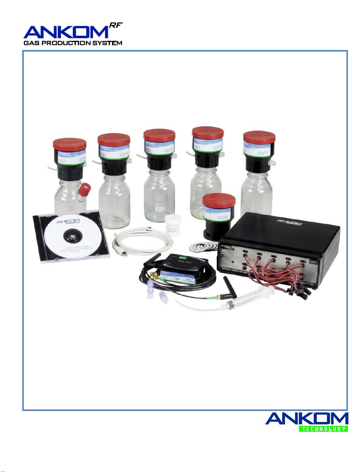
Congratulations on your purchase of the ANKOMRF Gas Production System. We are confident that this product
will effectively serve your needs.
This manual will provide you with details that will help you achieve the best possible results.
Warranty
ANKOM Technology warrants the ANKOMRF Gas Production System against any defects in workmanship or
material for one year after the original date of purchase. This warranty does not include damage to the instrument
resulting from neglect or misuse. During the warranty period, should any failure result from defects in
workmanship or materials, ANKOM Technology will, at its discretion, repair or replace the instrument free of
charge.
Extended warranties are available upon request.
Operating Temperature: 5-60°C
Contact Information
ANKOM Technology is committed to your total satisfaction, and is therefore always available to help you get the
most from your ANKOM products. We are also very interested in any comments or suggestions you may have to
help us improve.
For any questions or suggestions regarding your instrument, please contact us at:
Telephone: (315) 986-8090
Fax: (315) 986-8091
www.ankom.com
Rev F 8/29/14 pg. 5
Page 6

Operator’s Manual
This page intentionally left blank
pg. 6 Rev F 8/29/14
Page 7

Operator’s Manual
Instrument Description
General Description
The ANKOMRF Gas Production System is designed to measure the kinetics of a microbial fermentation in an
automated fashion by monitoring the gas pressure within multiple Modules and remotely recording the data in
computer spreadsheets. Equipped with a temperature sensor, each Module can also monitor the temperature of its
environment. The system can include up to 50 individual Modules that communicate information to a computer
using radio frequency (RF) transmission. From the computer interface the operator can control numerous variables
such as data recording intervals and the automatic release of pressure through internal valves in each Module.
Examples of Instrument Applications
Current and potential applications for the ANKOMRF Gas Production System include, but are not limited to, Rumen
Nutrition, Human Digestion, Yeast Activity, Biomass-to-Fuel, Biodegradability, Biochemical Oxygen Demand
(BOD), Soil Quality, and more.
Rev F 8/29/14 pg. 7
Page 8
Operator’s Manual
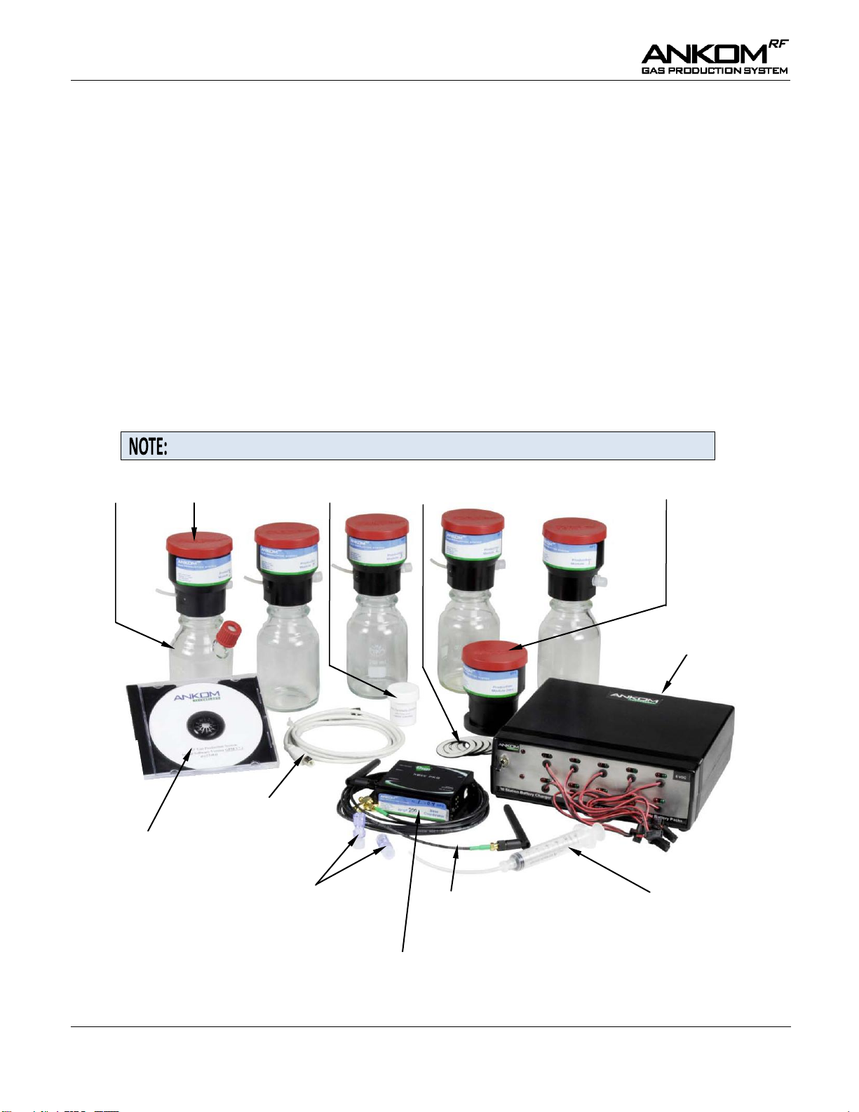
A Module connected to a Glass Bottle is referred to as a Module Assembly.
Glass Bottles
Modules
Synthetic Grease
Bottle Gaskets
Reference Module Zero
Luer Check Valves
with Caps
Antenna Extension
Assembly
Vent Valve Cleaning Kit
Battery Charger
CD with Operating
Software
USB Cable
Base Coordinator
System Components
The ANKOMRF Gas Production System Base Kit includes the following components:
5 – Modules (part # RF1)
5 – Glass Bottles (bottle types to be chosen by the customer) – there is one Glass Bottle for each Module
1 – Reference Module Zero (ambient pressure only – part # RF5)
6 – Rechargeable Battery Packs (part # RF16) – 1 in each Module and 1 in the Reference Module Zero
1 – 10 Station Battery Charger (part # RF25)
1 – Base Coordinator w/ USB Cable (part # RF2) and antenna (part # 7143)
1 – Antenna Extension Assembly (part # RF29)
1 – CD containing the Computer Drivers and Operating Software (part # RF3)
1 – Vent Valve Cleaning Kit (part # RF22)
2 – Luer Check Valves (part # 7139)
2 – Male Luer Caps (part # 7147)
5 – Bottle Gaskets (part # 7074)
1 – Sythetic Grease (part # RF41)
pg. 8 Rev F 8/29/14
Page 9
Operator’s Manual
Each ANKOMRF Gas Production System network requires a connection to a
unique laptop or desktop computer. The computer does NOT have to be
dedicated to the ANKOM system.
You must run GPM software version 9.7.1 or greater if you are adding
Modules with temperature sensors to an existing system. Existing Modules
can be upgraded to include temperature sensors. Contact ANKOM for details.
WARNING: For the 250 ml – 1000 ml narrow-mouth Glass Bottles, never
apply pressure exceeding 10 psi while purging your system (eliminating
oxygen), or allow the pressure in the Bottles to exceed 10 psi (685 mbar)
during an experiment.
For the 1.8 L wide-mouth bottles, never let pressure exceed 1 psi.
Always wear safety glasses and appropriate lab protection when handling the
Modules.
Using this system and/or its components in a manner not specified by the
manufacturer voids the warranty and may result in harm to the user.
Please review the entire contents of this manual before you begin operating
this product.
Adding Modules
The ANKOMRF Gas Production System has a modular design that allows the user to increase or decrease the
number of samples tested. The Reference Module Zero is used to monitor and record atmospheric pressure. The
Base Coordinator is used to communicate with up to 50 Modules each programmed with a unique ID number and
system address. If you have a system with less than 50 Modules, more can be ordered to complete your system.
When ordering additional Modules, it is important to let ANKOM know what Module numbers you currently have
(for example: 1-5) so that the new Modules can be programmed correctly for your system. The Module number is
displayed on the Module’s label and on the chip plugged into the circuit board. If your system is complete with 50
Modules and you would like to add more Modules, an additional RFS Base Kit is required. This second Base Kit
will communicate on a different network than the original. It is possible to have as many as 5 Base Kits and 250
Modules in a facility.
Safety Precautions
This system is designed to meet and/or exceed the applicable standards of CE, CSA, NRTL and OSHA.
Rev F 8/29/14 pg. 9
Page 10

Operator’s Manual
This page intentionally left blank
pg. 10 Rev F 8/29/14
Page 11
Operator’s Manual
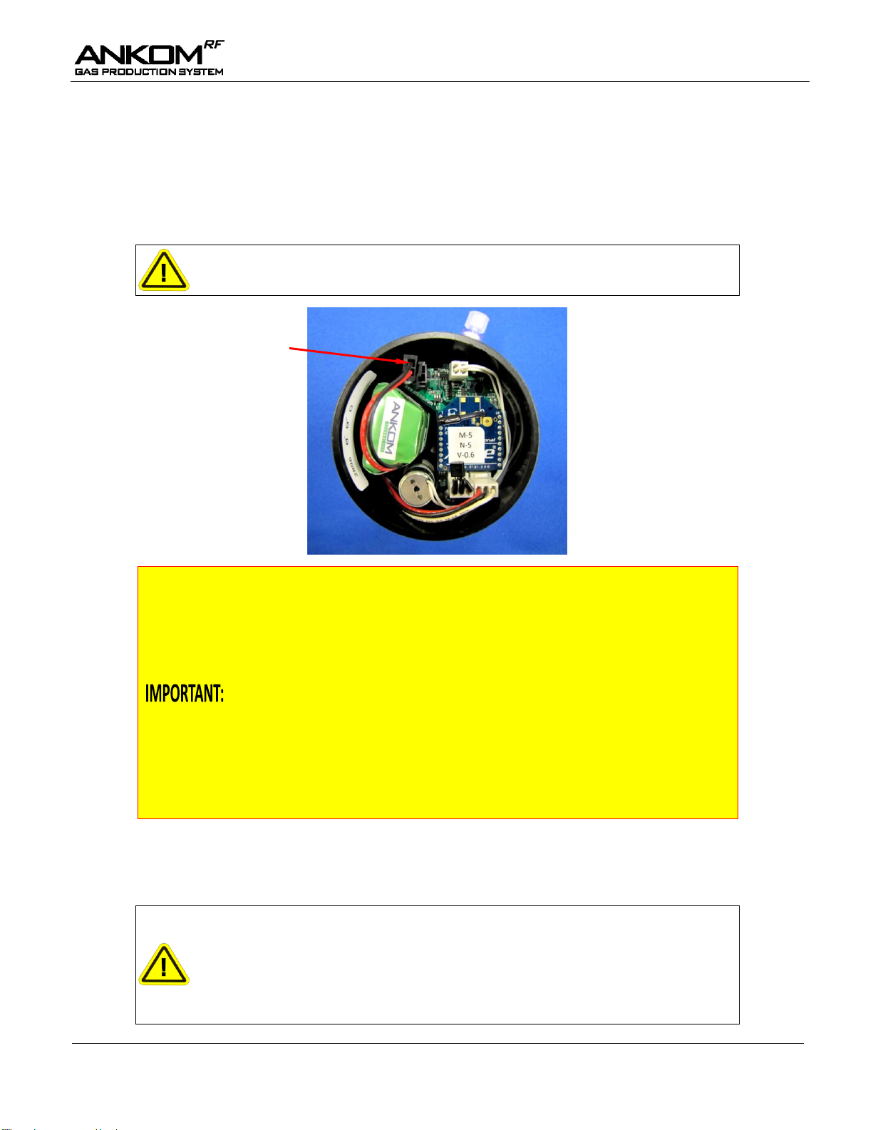
Caution: Damage to the circuit board and batteries can occur if the batteries
are connected backwards.
Rechargeable batteries lose charge when not being used.
Always charge your Rechargeable Battery Packs (part # RF16) for at least 3
hours just prior to their use. A fully charged battery when plugged into a
Module should read 6.7 volts or higher on the GPM software screen.
Typically, a fully charged Rechargeable Battery Pack should be able to power
a Module for at least 10 days under normal conditions (20-40°C, GPM
settings of 1 minute Live Interval and 1 Valve Open sequence per hour).
Individual performance may vary depending on testing conditions. Although
Modules will function properly, battery packs may have to be recharged at
more frequent intervals when operating at lower temperatures. When
running the system, remember to check the battery voltage daily and change
the battery pack when the voltage decreases to 6.3 volts or lower. Changing
the battery pack during the run will not affect the results.
Do not allow water into the Module: When placing a Module Assembly in
water, do NOT allow the water level to reach the vent tube or water damage
will occur. When using a water bath, do NOT cover the bath and the RF
modules with a lid as the trapped humidity will be detrimental to the
electronics. Instead, use bath balls to cover the surface of the water and
control the temperature and evaporation.
Battery Connection
Instrument Setup – Equipment
Battery Connection
Before using your system you must connect the battery packs within each Module by connecting the male
connector on the battery pack to the female connector on the circuit board. The locking tab must be facing the
adjacent white connector.
Temperature Control
The Module Assembly (includes the Module connected to a Glass Bottle) can be placed in a cabinet incubator or in
a shallow water bath to maintain appropriate temperatures.
Rev F 8/29/14 pg. 11
Page 12
Operator’s Manual
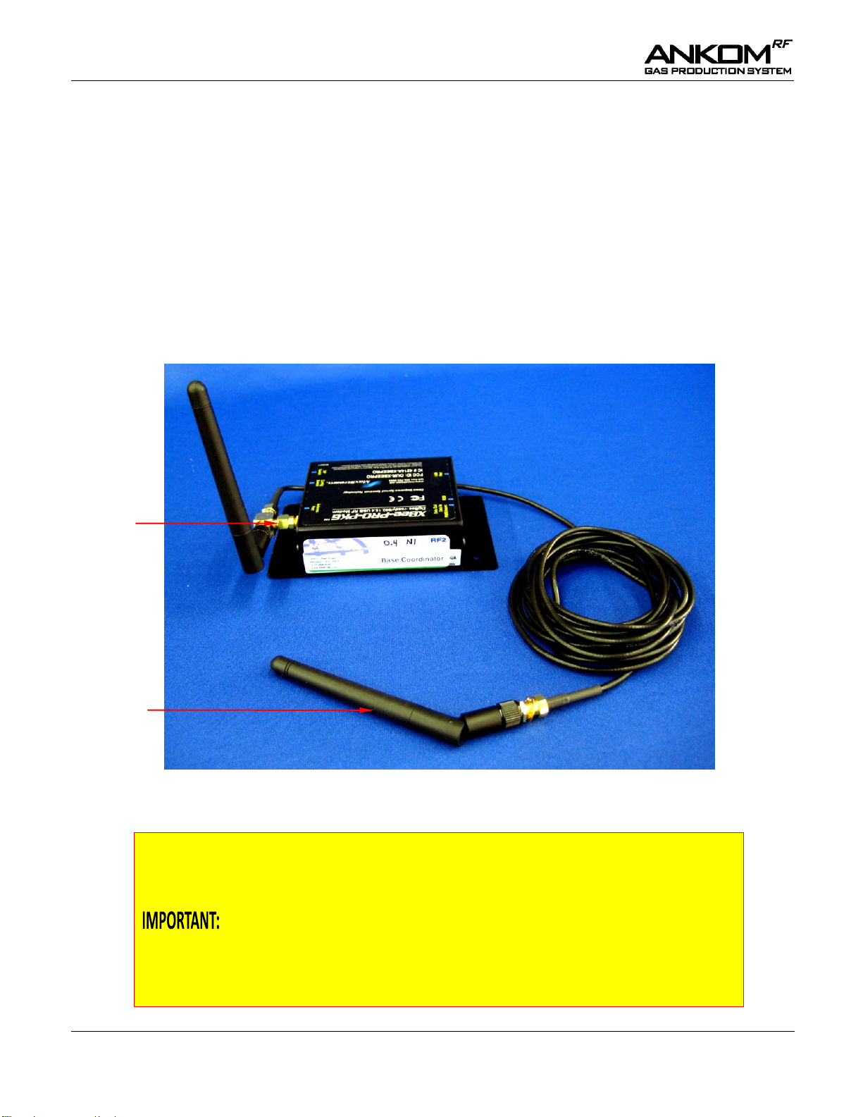
Antenna Extension Assembly (part # RF29) connected to the Base Coordinator
1) When using the extension, you should run the system with both antennas
connected as shown in the picture above. The antenna closest to the Base
Coordinator will pick up the Reference Module Zero signal while the
antenna connected to the end of the extension cable will pick up the signals
from the modules.
2) It is important to keep metal shelving or cabinets away from the Base
Coordinator and Modules to avoid interference with the component
antennas. Metal may disrupt radio frequency and may cause delays in
system communications.
"T"
fitting
7143
Antenna
RF Communication
Radio Frequency (RF) technology allows the Modules to be located away from the Base Coordinator without the
need for cumbersome wire connections. Although the RF signal from the Modules can be detected at distances of
10 ft. or more, for the best signal reception it is recommended that you place the Modules (including Reference
Module Zero) as close as possible to the Base Coordinator. If necessary, it is possible to extend the antenna from
the Base Coordinator with an ANKOM Antenna Extension Assembly (Part # RF29, shown below). This will allow
you to place the antenna closer to the Modules.
To install the antenna extension, follow the steps below:
(1) Screw the Antenna Extension Assembly (the female part of the “T” fitting) onto the Base Coordinator.
(2) Screw the original Antenna (part # 7143) onto the Antenna Extension Assembly at the male part of the
cable.
pg. 12 Rev F 8/29/14
Page 13
Operator’s Manual
You must run GPM software version 9.7.1 or greater if you are using Modules
with temperature sensors.
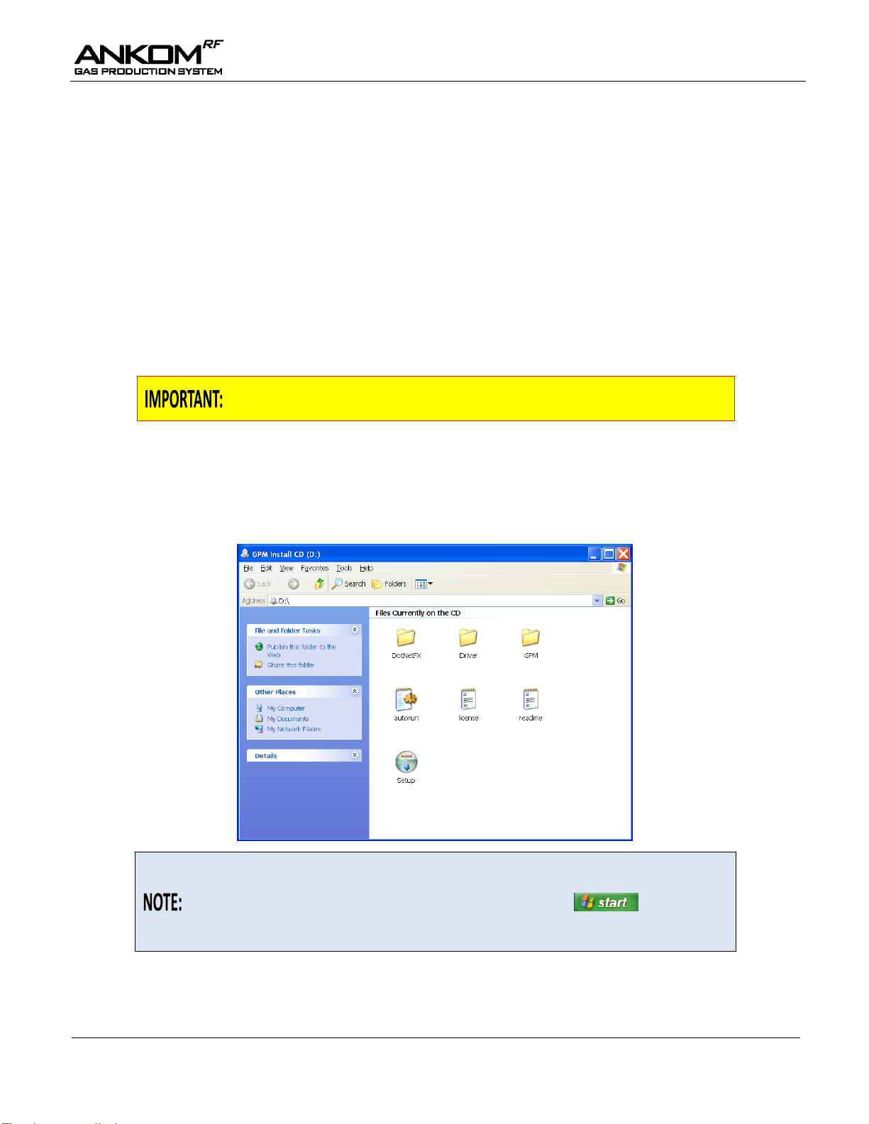
If the window above does not display automatically on your screen, then open
My Computer on your computer screen. (If the My Computer icon is not
already on your desktop, you can access it via the button in the
lower left corner of your desktop screen). With My Computer open, doubleclick on your CD device icon to open the window above.
Instrument Setup – Software
Computer Software Requirements
To run the GPM software, your computer must have the following programs.
Windows XP or later
Microsoft Excel 2003 or later
Internet Explorer 5.0 or later
Microsoft.Net
Windows Installer
If not already loaded, the ANKOMRF Gas Production System installation program will install:
Microsoft.Net
Windows Installer
Instrument Software Installation
To install your GPM software, follow the steps below:
(1) Insert the GPM CD into your computer. After a few moments, the following window should open
showing the contents of the CD.
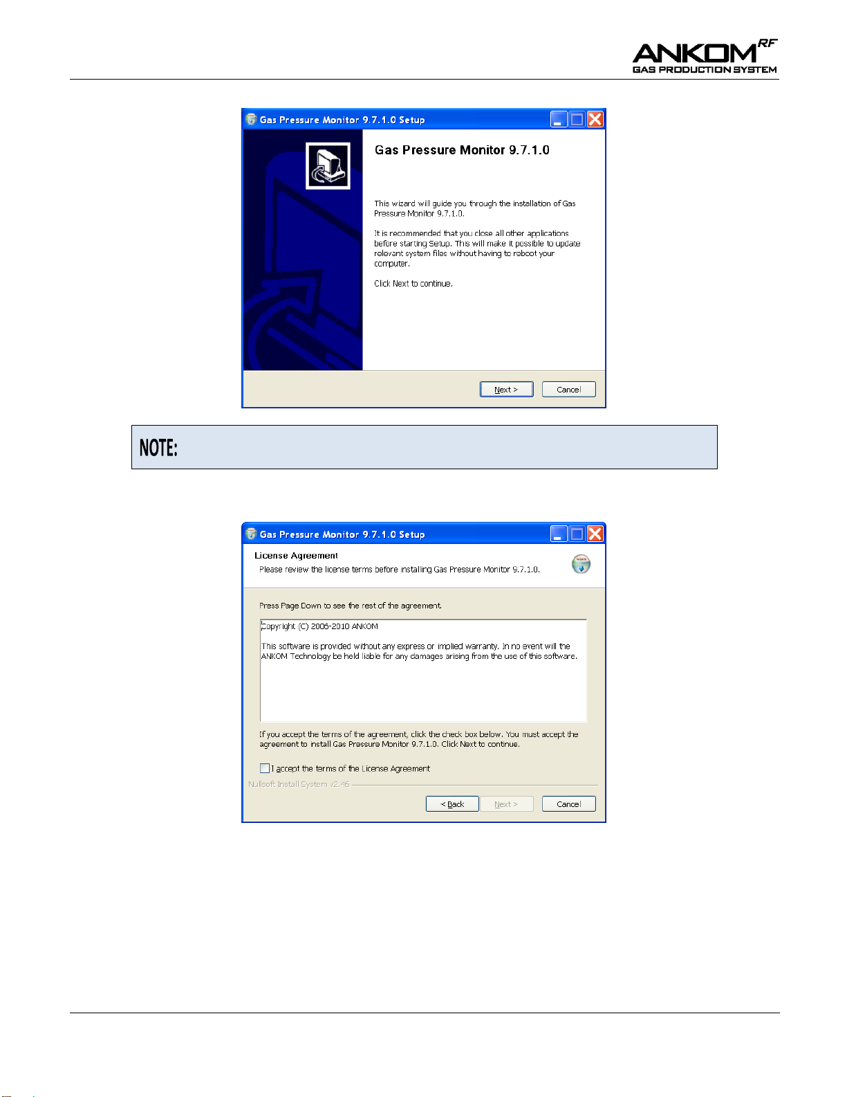
(2) Double-click the Setup icon in the window above. The following message box is displayed.
Rev F 8/29/14 pg. 13
Page 14
Operator’s Manual
The version number on this message box will correspond to the GPM
software version you are installing.
(3) Click the Next> button in the message box above to proceed with the software installation. The following
message box is displayed.
(4) In the message box above, put a check mark in the box () next to “I accept the terms of the License
Agreement” by clicking on the box.
(5) Click the Next> button and the following message box is displayed.
pg. 14 Rev F 8/29/14
Page 15
Operator’s Manual
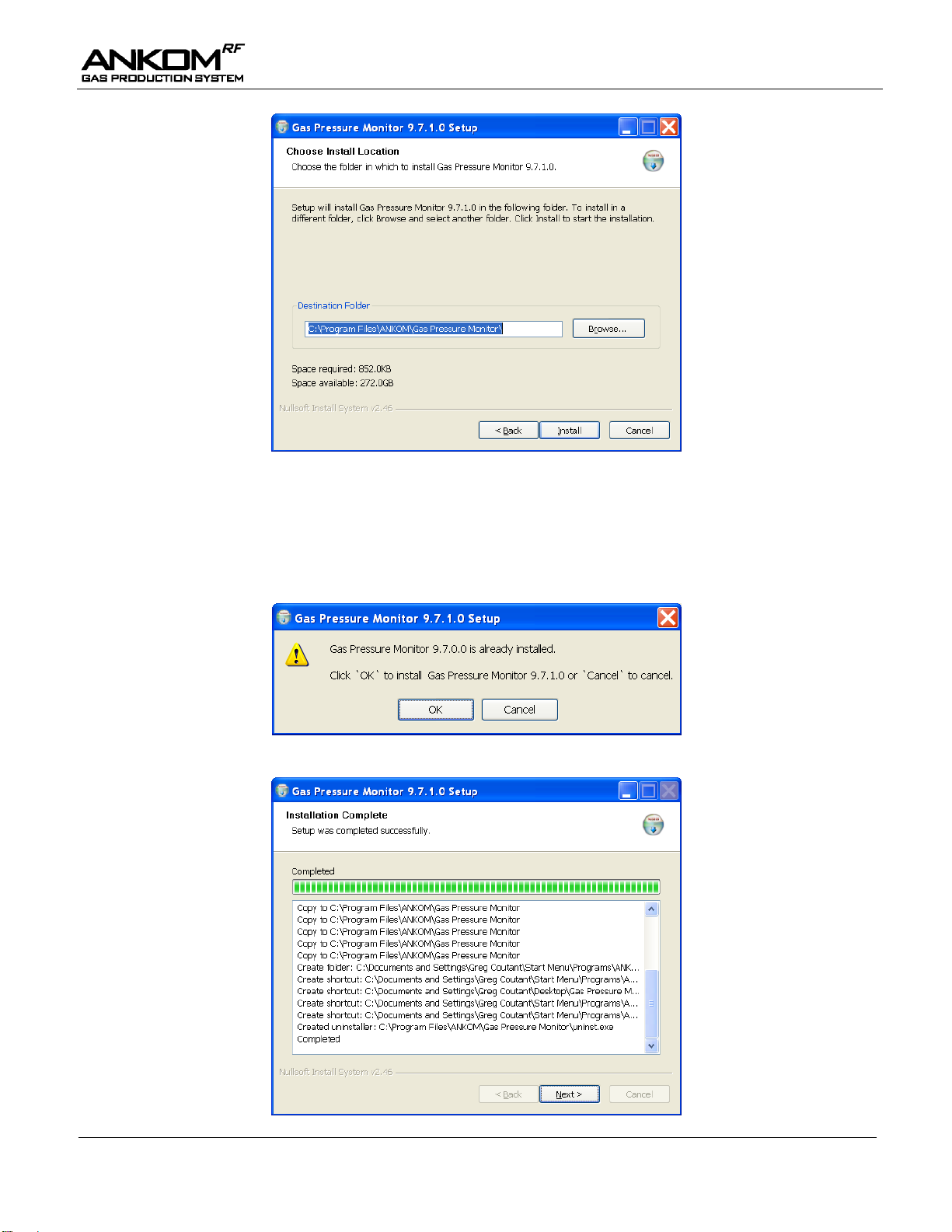
(6) In the message box above, the Destination Folder box shows the name of the folder path in which your
GPM software program will be stored. If the name is not what you want it to be, then type the name of
the folder, or click the Browse button to go to the folder in which you would like to store this program.
(7) In the message box above, click the Install button. If there is already a version of the GPM software
installed on your computer, the following message box will be displayed. Otherwise, you will see the
installation begin, in which case you can skip step #8 and go right to step #9.
(8) To load the updated GPM software, click the OK button. The following message box is displayed.
Rev F 8/29/14 pg. 15
Page 16

Operator’s Manual
Before running your GPM software, plug the Base Coordinator into a USB
port on your computer so the necessary drivers can be installed.
(9) When the message box above shows that the installation is complete, click the Next> button and the
following message box is displayed.
(10) If you want to immediately start the GPM software, then ensure that a check mark () is in the box next
to Run Gas Pressure Monitor x.x.x.x (this refers to the specific version of software that you are
installing) in the message box above. If it is not checked and you want it to be, then click the check box.
(11) To complete the installation, click the Finish button in the message box above.
After executing the Software Installation procedure detailed above, the GPM program is installed on your
computer and the following GPM icon is placed on your desktop.
To use the GPM software, double-click the GPM icon on your computer desktop.
pg. 16 Rev F 8/29/14
Page 17

Operator’s Manual
A “cell” is one element of data within either the Live View table or the
Recording View table. See the Screen layout section below for more details.
A cell is shaded LIGHT BLUE when the pressure within that Module climbs above the Pressure
Release value specified for the respective Module. When this happens, at the next live interval the
valve briefly opens and vents the gas until the pressure is correct.
A cell is shaded ORANGE when the Module has not communicated with the computer for at least 5
minutes of continuous time.
A cell is shaded GREEN when the battery voltage for the associated Module is 6.3 volts or higher.
A cell is shaded YELLOW for one of two reasons:
(1) the battery voltage for the associated Module is greater than 6.0 and less than 6.3 volts, or
(2) a Module has re-established communications with the computer after being disconnected for
at least 5 minutes. Cells in the Recording View turn from ORANGE to YELLOW when this
happens.
A cell is shaded RED when the battery voltage for the associated Module is 6.0 volts or lower.
When no Reference Module Zero is connected, the Current Pressure cell in column zero of the Live
View is shaded PINK and displays a pressure of 14.5. If data recording begins with no Reference
Module Zero connected, cells in column zero of the Recording View are shaded PINK and display a
pressure of 14.5.
Instrument Software Functionality
Color Coding Definitions
The GPM software uses a color coding scheme to help you clearly identify specific conditions within your data. As
you review the rest of this document, and as you work with your system, please keep in mind the following color
coding definitions.
Rev F 8/29/14 pg. 17
Page 18

Operator’s Manual
Auto Graphing
In addition to capturing the data points for pressure and temperature, the GPM software has an Auto Graphing
capability that displays line graphs for the cumulative pressure and absolute temperature for each selected Module
within a study. The pressure and temperature graphs can be viewed on separate screens or together on one screen.
Examples of these graphs are shown below.
Sections of each graph can be enlarged by holding down the left button on the computer mouse and dragging the
cursor over the section of interest.
You can also pan to different parts of the graph by holding the center mouse button and dragging the computer
mouse.
pg. 18 Rev F 8/29/14
Page 19

Operator’s Manual
The “Set Scale to Default” option has no function within this application.
The Auto Graphing capability is meant to provide the user with a visual
indication of the data being recorded during the gas study. However, the
graphs themselves are NOT automatically stored after the study is complete.
To save the graphs from the Auto Graphing feature, you can either:
(1) right click while on the graph screen and select “Save Image As…”, or
(2) right click while on the graph screen and select “Copy”, or
(3) do a Print Screen.
Please note that all of the raw data is stored in MS-Excel format. Therefore,
you can always recreate a graph from the stored data by using the graphing
feature within MS-Excel.
When you right click on any of the graphs, the following menu will be displayed:
From this menu, you have the following options:
Copy – copies the graph to the clipboard, from which it can be pasted into a document.
Save Image As – saves the graph in a selectable image format.
Change background color – allows the user to change the background color of the graphs.
Change line color – allows the user to change the colors of the graph lines.
Page Setup – allows for modifications to the print configuration.
Print – prints the graph.
Show Point Values – allows the user to identify data points when hovering over the graph with the
computer mouse.
Un-Zoom – returns the graph to the default view if the graph has been enlarged.
Undo All Zoom/Pan – returns the graph to the default view if any zooming or panning has occurred.
Rev F 8/29/14 pg. 19
Page 20

Operator’s Manual
1
2
3
4
5
6
7
8
9
10
11
12
13
14
15
16 17 18 19 20 21 22
23
24
25
26
27
28
29
30
Live View
Recording View
Configuration View
Browse
Version: 9.8.3
Screen layout
The screen below contains all the controls and data associated with the operation of this system. In this document
we have added some numbers in RED to the screen image to identify the functions described below. These
numbers will NOT show on your computer screen.
The main screen is divided into 3 sections:
Configuration View The Configuration View is on the left side of the GPM screen and it displays the
configurable features of the program. Parameters in the Configuration View are saved
when you exit the program.
Live View The Live View is at the top of the GPM screen and it displays the current status of the
modules. The status will be updated based on the time interval specified in the Live
Interval box on the Configuration View.
Recording View The Recording View is in the center part of the GPM screen and it displays the data
recorded during the use of the system (tabs numbered 16 – 19) along with data graphs
(tabs numbered 20 – 22) that are automatically generated to provide the user with a
visual indication of the data being recorded during the gas study. The graphs from tabs
20 – 22 are NOT automatically stored after the study is complete. (See the “Auto
Graphing” section in this manual for further details.)
pg. 20 Rev F 8/29/14
Page 21

Operator’s Manual
For best results the Live Interval should be set so that there are at least 2 Live
Intervals for every Recording Interval. For example, if you want to record data
every 2 minutes, you should set the Recording Interval to 2 minutes and the Live
Interval to 60 seconds or less.
Holding the vent valve open may reduce battery voltage. Before clicking the
Record button on your GPM screen to start a study, replace batteries that show
6.6 volts or lower.
The GPM software will not allow a release pressure greater than 10 psi. For
1.8L wide-mouth bottles, it is recommended that you set the release pressure to
a value no greater than 1 psi.
Set your Pressure Units before you click the Record button. You can NOT
change them while the experiment is running and the system is collecting data.
The data points in the saved Excel spreadsheet are time-stamped with actual
clock time instead of incremental elapsed time.
Following is a description of the individual components displayed on the GPM screen.
1 Live Interval – This box contains the time gap (in seconds) between each instance of Module-to-computer
communication. This interval can contain values up to 60 sec. During setup this time frame is usually set
to very short intervals to permit rapid responses to manual commands. Longer live intervals are
recommended during studies to preserve battery life.
2 Recording Interval – This is the time between recordings of the pressure readings. Changing this value
has no impact on battery life.
3 Open Valves – When you click this button you open all valves at one time (at the next live interval).
After clicking this button you will see a check mark () in each cell of the Valve Open row that has a
live module. To preserve battery life, the valves will only remain open for 3 minutes.
Close Valves – When you click this button you close all valves at one time (at the next live interval).
After clicking this button you will see a blank box () in each cell of the Valve Open row.
4 Global Release – The value in this box is used for all modules as the upper threshold value above which
pressure will be automatically released from the system. After entering a value, click the Set button so the
value is recognized by the system. You can still change the value for each individual module if you
desire.
5 Pressure Units – You can select psi or mbar units to apply to the value entered into the Global Release
box and to the values being recorded by the system.
6 Temperature Units – You can select Fahrenheit or Celsius.
7 Record – When you click this button you start recording the pressure and temperature data.
Stop – When you click this button you stop recording the pressure and temperature data and stop the
study.
8 Elapsed Time – This box displays the period of time that the system has been recording data.
9 Save – When you click this button a screen is displayed that says “Saving Experimental Results.” This
allows you to create an Excel file name and a file location within your computer system for the data on
the spreadsheet to be stored. You can save the file any time during the run.
Rev F 8/29/14 pg. 21
Page 22

Operator’s Manual
You should change the autosave file name before every run to minimize the
possibility of data loss.
Holding the vent valve open may reduce battery voltage. Before clicking the
Record button on your GPM screen to start a study, replace batteries that show
6.6 volts or lower.
10 Autosave location – The GPM program automatically stores recorded data at the Autosave location. If
the file name in the Autosave location is NOT changed between data recording sessions, the file will be
overwritten each time a recording is made.
In the Autosave location box, you can enter the file location (file path\file name) where you want the
autosave data stored. You can use the Browse button to get you to the file path folder where you want to
store the data file. The program will automatically add the file name of "AutoSave.xls" to the file path
that you selected. To establish a new file name, delete "AutoSave.xls" and type in the new name
including the ".xls" extension.
11 Valve open time – The value you enter in this box controls how long the vent valve remains open in
order to maintain the Pressure Release setting. The default value is 250 milliseconds, but any value less
than 1000 milliseconds may be entered. A smaller value provides more accurate control of the pressure,
but takes longer to accommodate a large pressure change. Conversely, a larger value provides a faster
response but with less accuracy. After entering a value, click the Set button so the value is recognized by
the system.
12 Coordinator – This displays the status of the Base Coordinator. If there is no Base Coordinator
connected, then “Not Connected” is displayed. When a Base Coordinator is connected and recognized by
the computer, then “Connected” is displayed.
13 Network – A network contains 1-computer, 1-Base Coordinator, and 1-Reference Module Zero. You can
have up to 50 Modules on one network. If you need more than 50 Modules you will need another
network. The new network will have a different network number. The number shown on your screen
represents the network whose data is being captured by that computer.
14 Version – This displays the version of the GPM software that is running.
15 Temperature calibration settings – When you click this button the following screen is displayed.
pg. 22 Rev F 8/29/14
Page 23

Operator’s Manual
Stabilization times may be different depending on the temperature of the
environment.
If all of your Modules will be in the same temperature environment, you can
enter the temperature from your stabilized standard thermometer in the “All” box
and click the SET button. This will place the same value in all of the cells.
To lock in any changes on the Temperature calibration settings screen, including
blanking all of the cells by clicking the Remove calibration values button, you
must always apply them.
To apply settings, you can click the APPLY button, or you can click the CLOSE
button and click the YES button on the popup screen.
To exit the Temperature calibration settings screen without saving any changes,
you can do one of the following:
1) Click the CLOSE button and click the NO button on the popup screen.
2) Click the in the top right corner of the screen.
When you enter values on the Temperature calibration settings screen and apply
them, the GPM software generates offset values for the specified Modules. These
offsets will be applied to the same Modules for every run until a new calibration
is done. Since the calibration settings are associated with Modules and not
specific sensors, you should re-calibrate if you remove a temperature sensor from
a Module and install it in a different Module.
The Temperature calibration settings can only be changed before the Record
button on the GPM screen has been clicked.
The temperature sensors are accurate to within 2°C over a range of 5°C – 60°C. To account for any
Module-to-Module differences in temperature sensing capability, you can calibrate each sensor using the
Temperature calibration settings screen. The values entered in the cells on this screen are used by the
GPM software to determine the appropriate offsets to apply to each sensor to calibrate them to the
temperature of your standard source.
To calibrate your Module sensors, follow the steps below:
(1) Plug the batteries into the Modules intended for your study.
(2) Place the Modules along with a reliable thermometer in the same location and let them
stabilize for a reasonable amount of time.
(3) Start the GPM software.
(4) Click the Temperature calibration settings button on the GPM software screen.
(5) Type the temperature reading from your stabilized standard thermometer into the cells of the
Modules that you are using for your study.
(6) Click the APPLY button on the Temperature calibration settings screen to lock in the values.
16 Cumulative Pressure tab – When you click this tab you will see the cumulative pressure data for the
times specified by the Recording Interval. This is the default data view for the program.
Rev F 8/29/14 pg. 23
Page 24

Operator’s Manual
Browse
Version: 9.8.3
17 Absolute Pressure tab – When you click this tab you will see the absolute pressure data for the times
specified by the Recording Interval. An example of this screen is shown below.
pg. 24 Rev F 8/29/14
Page 25

Operator’s Manual
Browse
Version: 9.8.3
18 Temperature tab – When you click this tab you will see the temperature data for the times specified by
the Recording Interval. An example of this screen is shown below.
Rev F 8/29/14 pg. 25
Page 26

Operator’s Manual
Browse
Version: 9.8.3
19 Battery Voltage tab – When you click this tab you will see the battery voltage for the battery packs in
each Module for the times specified by the Recording Interval. An example of this screen is shown
below.
pg. 26 Rev F 8/29/14
Page 27

Operator’s Manual
The graph above represents a yeast study done with different amounts of yeast
and sugar in each bottle in ambient conditions without any temperature controls.
The Auto Graphing capability is meant to provide the user with a visual
indication of the data being recorded during the gas study. However, the graphs
themselves are NOT automatically stored after the study is complete.
To save the graphs from the Auto Graphing feature, you can either:
(1) right click while on the graph screen and select “Save Image As…”, or
(2) right click while on the graph screen and select “Copy”, or
(3) do a Print Screen.
Please note that all of the raw data is stored in MS-Excel format. Therefore, you
can always recreate a graph from the stored data by using the graphing feature
within MS-Excel.
Browse
Version: 9.8.3
20 Cumulative Pressure Graph – When you click this tab you will see a line graph of the cumulative
pressure data that has been recorded to that point. A Module’s graph will only be displayed if its box in
the Show Graph Line row is checked. An example of this screen is shown below.
Rev F 8/29/14 pg. 27
Page 28

Operator’s Manual
The graph above represents a study done in ambient conditions without any
temperature controls.
The Auto Graphing capability is meant to provide the user with a visual
indication of the data being recorded during the gas study. However, the graphs
themselves are NOT automatically stored after the study is complete.
To save the graphs from the Auto Graphing feature, you can either:
(1) right click while on the graph screen and select “Save Image As…”, or
(2) right click while on the graph screen and select “Copy”, or
(3) do a Print Screen.
Please note that all of the raw data is stored in MS-Excel format. Therefore, you
can always recreate a graph from the stored data by using the graphing feature
within MS-Excel.
Browse
Version: 9.8.3
21 Temperature Graph – When you click this tab you will see a line graph of the absolute temperature data
that has been recorded to that point. A Module’s graph will only be displayed if its box in the Show
Graph Line row is checked. An example of this screen is shown below.
pg. 28 Rev F 8/29/14
Page 29

Operator’s Manual
The graphs above represent a yeast study done with different amounts of yeast
and sugar in each bottle in ambient conditions without any temperature controls.
The Auto Graphing capability is meant to provide the user with a visual
indication of the data being recorded during the gas study. However, the graphs
themselves are NOT automatically stored after the study is complete.
To save the graphs from the Auto Graphing feature, you can either:
(1) right click while on the graph screen and select “Save Image As…”, or
(2) right click while on the graph screen and select “Copy”, or
(3) do a Print Screen.
Please note that all of the raw data is stored in MS-Excel format. Therefore, you
can always recreate a graph from the stored data by using the graphing feature
within MS-Excel.
Browse
Version: 9.8.3
22 Cumulative Pressure/Temperature Graph – When you click this tab you will see a line graph of the
absolute temperature data that has been recorded to that point and a line graph of the cumulative pressure
data that has been recorded to that point. A Module’s graph will only be displayed if its box in the Show
Graph Line row is checked. An example of this screen is shown below.
Rev F 8/29/14 pg. 29
Page 30

Operator’s Manual
The text typed into a Module Name cell does not wrap when the text reaches
the end of the cell. Therefore, if you type a long name in the cell, the column for
that Module will widen and reduce the amount of data that can be viewed on
one screen.
If the Module Name cell turns ORANGE during a run, first try unplugging the
battery pack for that Module and plugging it back in. This resets the Module.
This could result in some missing data points while the reset is occurring.
However, data captured before and after the reset will remain.
Browse
Version: 9.8.3
23 Module Name – Cells within this row display the Module identification number or name. By default,
these cells display numbers. To change a cell within the Module Name row, highlight the cell and type.
This cell becomes ORANGE when the Module has not communicated with the computer for at least 5
minutes. An example of an indication of communication loss is shown below.
pg. 30 Rev F 8/29/14
Page 31

Operator’s Manual
Holding the vent valve open may reduce battery voltage. Before clicking the
Record button on your GPM screen to start the study, replace batteries that
show 6.6 volts or lower.
The GPM software will not allow a release pressure greater than 10 psi. For
1.8L wide-mouth bottles, it is recommended that you set the Pressure Release
to a value no greater than 1 psi.
Browse
Version: 9.8.3
If a Module that had previously lost communication regains communication, the module name cell in the
Recording View turns YELLOW (see below) and remains YELLOW through the rest of the run.
24 Valve Open – Clicking a cell within this row puts a check mark in the box () and opens the vent valve
for that specific Module for a maximum of 3 minutes. Clicking the cell again removes the check mark
() and closes the specific vent valve. This should NOT be done during a study because the computer
will not record any pressure loss during this operation. This function allows you to open and close valves
for individual Modules. Remember that you can open and close all valves at once by using the Open
Valves and Close Valves buttons in the Configuration View.
25 Pressure Release – Cells in this row display the maximum pressure setting for the respective Module
relative to the Reference Module Zero pressure. If pressure within a module climbs above this value, the
valve will briefly open and vent the gas at the next live interval. The Current Pressure cell will turn
LIGHT BLUE when this occurs. The computer automatically accounts for pressure lost during this valve
venting. Once the Pressure Release value has been entered on your computer screen, press <Tab> or
<Enter> on your computer keyboard to activate that Module.
Rev F 8/29/14 pg. 31
Page 32

Operator’s Manual
Since the GPM software cannot determine if a temperature sensor is present or
failing, the user should look at each Temperature cell on the GPM screen
before and during a study to make sure that the readings make sense.
Although a Module will function at 6.0 volts, it may not have enough power to
consistently operate the valve. Therefore, before starting a study, ensure that
your rechargeable batteries are fully charged to 6.7 volts or higher.
A battery pack can be replaced during a study without loss of functionality.
There could be some missing data points during the period when the battery was
being replaced. However, data captured before and after the battery pack
replacement will remain.
26 Current Pressure – Cells in this row display the current pressure within the bottle relative to the
Reference Module Zero pressure and represents the most recent pressure reading reported during the last
Live Interval. A LIGHT BLUE cell indicates that the Current Pressure is above the Pressure Release
threshold.
27 Cumulative Pressure – Cells in this row display the sum of the incremental changes in pressure for the
specific Module recorded throughout the entire study. This pressure is NOT positively or negatively
affected by valve releases that are initiated by the software based on the Pressure Release value that you
entered. This pressure is affected by opening and closing individual valves using the Valve Open feature
in the Live View, or by opening and closing all valves at once using the Open Valves and Close Valves
buttons in the Configuration View.
28 Temperature – Cells in this row display the value reported by the temperature sensor in the specific
Module.
29 Battery Voltage – Cells in this row display the current battery voltage for the specific Module. The cell
is GREEN when the voltage is 6.3 volts or higher, YELLOW when the voltage is greater than 6.0 and
less than 6.3 volts, and RED when the voltage is 6.0 volts or lower.
30 Show Graph Line – Clicking a cell within this row puts a check mark in the box () for that specific
Module. Clicking the cell again removes the check mark (). The Auto Graphing capability will only
display a graph for a Module that has a check mark () in its cell within this row.
pg. 32 Rev F 8/29/14
Page 33

Operator’s Manual
Caution: The temperature sensors are NOT submersible. Placing electrical
parts in conductive material could cause physical harm and could damage the
system electronics.
Temperature Sensor
Temperature Sensing
Each Module comes equipped with a temperature sensor that can monitor the temperature of its environment.
The sensors are accurate to within 2°C over a range of 5°C – 60°C. To account for any Module-to-Module
differences in temperature sensing capability, the GPM software provides a calibration screen that can be used
before data recording begins. See the Instrument Software Functionality section of this manual for details about
calibrating the temperature sensors.
The standard sensor assembly is mounted inside the Module electronics assembly. As a result, it will not directly
measure the temperature inside of the bottle or the temperature of the material contained within the bottle.
However, over time the temperatures of the outside environment, the inside of the Module electronics assembly,
and the inside of the bottle will equilibrate. At that time the standard sensor assembly will provide a reasonable
representation of the temperature in the environment outside and inside of the bottle.
If you want the temperature sensor to directly measure the temperature outside of the electronics module, ANKOM
provides an extension cable that can be used to extend the temperature sensor to a location outside of the electronics
module. Along with a modified Module cap, the extension cable can be ordered from ANKOM in any size up to
and including 24 inches. The pictures below show a 6 inch extension cable plugged into a Module.
Rev F 8/29/14 pg. 33
Page 34

Operator’s Manual
This page intentionally left blank
pg. 34 Rev F 8/29/14
Page 35

Operator’s Manual
If Reference Module Zero is not connected, a default value of 14.5 psi is used
for ambient pressure.
Holding the vent valve open may reduce battery voltage. Before clicking the
Record button on your GPM screen to start a study, replace batteries that show
6.6 volts or lower.
To open the vent valve, click the Valve Open box on your GPM screen so that a
check mark appears in the box (). (To preserve battery life, the valve will
remain open for a maximum of 90 seconds.) To close the vent valve, click the
Valve Open box to remove the check mark ().
4.1 On your GPM screen, change Live Interval to 1 second and Recording Interval to 1 minute.
4.2 Press Record on your computer screen to start
recording pressure data.
4.3 Attach a Luer Check Valve to the Luer Port of each
Module you want to test.
Luer Check Valve
Luer Cap
Operating Instructions
To conduct a study with the ANKOMRF Gas Production System, follow the steps below:
1. Start your GPM software.
On your computer monitor, click the GPM icon to start the program. If the batteries are plugged into the
Modules, the program should display the battery voltage and pressure of each Module Assembly, including
the Reference Module Zero. (Reference Module Zero measures the ambient pressure and has no Glass Bottle
attached to it.)
2. Test that each Module is communicating with the computer.
To test communication between the Modules and the computer, use the following procedure:
2.1 Connect the Base Coordinator to your computer.
2.2 Plug Battery Packs into each of the Modules you want to test.
2.3 Verify that the GPM software recognizes each Module (your GPM screen will display a battery
voltage for each Module that it recognizes).
3. Clean and sterilize the Modules and Bottles before beginning operation.
It should be standard practice after each use to clean the underside of the black module housing with warm
soapy water. When this is done it is critical that water not get into the module or the electronics will be
damaged. Do not autoclave or submerse the module (even with the lid on) or allow water to enter the gap
around the side vent tube. Appendix A should be used for cleaning of the vent valve and tubing, as needed.
With the modules cleaned, it is recommended that they be sterilized with alcohol before use. Drying can be
expedited at up to, but not exceeding, 60°C. The glass bottles that come with your ANKOM RF Gas
Production System are plastic-coated for safety. As such they are not rated for autoclave sterilization. As
with the rest of the system do not heat the bottles beyond 60°C. Clean the bottles with warm soapy water.
Rinse and sterilize with alcohol. Drying can be expedited at up to, but not exceeding, 60°C.
4. Test the vent valve operation for each Module.
You can test vent valve operation by using either Luer Check Valves or the Vent Valve Cleaning Kit. To
verify vent valve operation using Luer Check Valves, follow the steps below:
Rev F 8/29/14 pg. 35
Page 36

Operator’s Manual
WARNING: For 250 ml – 1000 ml narrow-mouth bottles, never allow the
pressure in the bottles to exceed 10 psi. For 1.8 L wide-mouth bottles, never
allow the pressure in the bottles to exceed 1 psi. Always wear safety glasses and
appropriate lab protection when handling the Modules and Glass Bottles.
4.12 Pull back the plunger on the syringe part of the Vent Valve Cleaning
Kit.
4.13 Attach the Vent Valve Cleaning Kit to the Module you want to test by
gently pushing the barbed end of the Vent Valve Adapter into the vent
valve tube on the side of the housing.
WARNING: For 250 ml – 1000 ml narrow-mouth bottles, never allow the
pressure in the bottles to exceed 10 psi. For 1.8 L wide-mouth bottles, never
allow the pressure in the bottles to exceed 1 psi. Always wear safety glasses and
appropriate lab protection when handling the Modules and Glass Bottles.
4.4 Remove the Luer Cap and pressurize each Glass Bottle by applying 6-10 psi to each Module’s
Luer Check Valve. Verify on the screen that the Modules have pressure. Put the Luer Cap back
on the valve.
4.5 Monitor the pressure for 6-10 minutes, making sure there is not a significant drop in pressure.
Small changes from handling and ambient temperatures are normal.
4.6 On your GPM screen, click the Valve Open box for each Module you are testing to open the
valve.
4.7 Verify that the pressure drops when the vent valve opens for that Module (it should take
between 1-60 seconds to release, depending on how many Modules you have connected).
4.8 Verify that the pressure drops to zero.
4.9 On your GPM screen, click the Valve Open box for each Module you are testing to close the
valve.
To verify vent valve operation using the Vent Valve Cleaning Kit, follow the steps below:
4.10 On your GPM screen, change Live Interval to 1 second and Recording Interval to 1 minute.
4.11 On your GPM screen, press Record to start recording pressure data.
4.14 On your GPM screen, click the Valve Open box for each Module you are testing to open the
valve.
4.15 Pressurize the Glass Bottle by pushing the syringe plunger. While pressurizing, click the Valve
Open box on your GPM screen for each Module you are testing to close the valve.
4.16 On your GPM screen, verify that the Module has pressure.
4.17 Remove the Vent Valve Cleaning Kit by holding the vent valve tube against the housing with
your finger (to avoid stretching it), and pulling the adapter out.
4.18 Monitor the pressure for 6-10 minutes, ensuring there is not a significant drop in pressure.
Small changes from handling and ambient temperatures are normal.
4.19 On your GPM screen, click the Valve Open box for each Module you are testing to open the
valve.
4.20 Verify that the pressure drops when the vent valve opens for that Module (it should take
between 1-60 seconds to release, depending on how many Modules you have connected).
4.21 Verify that the pressure drops to zero.
4.22 On your GPM screen, click the Valve Open box for each Module you are testing to close the
valve.
pg. 36 Rev F 8/29/14
Page 37

Operator’s Manual
Do not allow water into the Module: When placing a Module Assembly in
water, do NOT allow the water level to reach the vent tube or damage will
occur. When using a water bath, do NOT cover the bath and the RF modules
with a lid as the trapped humidity will be detrimental to the electronics. Instead,
use bath balls to cover the surface of the water and control the temperature and
evaporation.
The gas permeability rate of 0.02 psi/hr is only a reference. This is NOT to be
applied broadly. Use the results of your Blank as the correction factor.
Do NOT use any sample (substrate) in the Glass Bottle used as the Blank.
If a Module is not holding pressure, re-apply pressure (using either of the two methods above) and perform
the following checks:
4.23 Place a small amount of soapy water on the end of the vent valve tube. If it is leaking, clean the
tube using the procedure in Appendix A.
4.24 Place a small amount of soapy water on the Luer Port. If it leaks it will need to be replaced
(Luer Port part # 7147). To replace the port, unscrew it and clean the threads in the housing.
Then apply a sealant (e.g., Locktite 425 or Teflon tape) to the threads on the new port and screw
it into the housing until snug. Check for leakage from the threads.
4.25 Check the Glass Bottle seal by either placing it in water just above the connection, or by holding
the bottle upside down and looking for bubbles after applying soapy water to threads. If leaking
is detected, inspect the bottle gasket (part # 7074) and replace as needed.
5. Prepare the Buffer to be used in your study.
See Appendix B for examples of Buffer Preparation used in Rumen studies.
6. Prepare the Inoculum to be used in your study.
See Appendix B for examples of Inoculum Preparation used in Rumen studies.
7. Prepare the Sample (substrate) to be used in your study.
Depending upon how fermentable the sample is, the quantity of sample will vary. In addition to the quantity
of fermentable sample, the length of time the incubation is conducted must be taken into consideration. The
quantities of sample and buffer may be sufficient for a 24 hour incubation, but they may not be sufficient for
a 48 hour incubation. By measuring the pH at the end of the incubation period you can determine if the
buffer maintained the proper pH throughout the incubation. This will allow you to alter the sample-to-buffer
ratio to fit the desired incubation period.
See Appendix B for further information about Samples used in Rumen studies.
8. Add Buffer and Inoculum to the Blank to be used in your study.
When running a study using the ANKOMRF Gas Production System, corrections must be made for the
following two factors:
Gas produced by the inoculum.
Gas lost by slight permeability of CO2 through the elastomeric components of the system (in a
pure CO2 environment under 2 psi pressure, studies show that the permeability rate is 0.02 psi/hr).
Running a blank in your study will correct for both factors.
Place buffer and inoculum in the Glass Bottle used as a Blank.
Rev F 8/29/14 pg. 37
Page 38

Operator’s Manual
You will need a source of CO2 regulated to 8-10 psi for this procedure.
WARNING: For 250 ml – 1000 ml narrow-mouth bottles, never allow the
pressure in the bottles to exceed 10 psi. Always regulate incoming purge
pressure down to 10 psi or less before purging bottles. For 1.8 L wide-mouth
bottles, never allow the pressure in the bottles to exceed 1 psi. Always wear
safety glasses and appropriate lab protection when handling the Modules and
Glass Bottles.
Holding the vent valve open may reduce battery voltage. Before clicking the
Record button on your GPM screen to start a study, replace batteries that show
6.6 volts or lower.
Luer Port
Purge Air Gun
(part# RF28 – sold separately)
9. Eliminate the oxygen from the Glass Bottle used as a Blank (i.e., purge the bottle).
If you are running a study that includes anaerobic organisms, then eliminate the oxygen from the Glass Bottle
used as a Blank by following the procedure below.
9.1 After adding inoculum to the Glass Bottle and with it in position to reattach to its Module (when
using wide-mouth bottles with metal clip closures leave the lid slightly open so that it can be
quickly closed), add CO2 directly into the top of the bottle until the CO2 fills the Module’s Glass
Bottle. This could take about 5 to 30 seconds depending upon the size of the bottle.
9.2 Immediately reattach the Module to the Glass Bottle.
9.3 On your GPM screen, set the Live Interval to 1 sec to speed up the valve open and close
operation.
9.4 On your GPM screen, set the Global release to 8 psi and set the Valve open time to 1000 ms.
9.5 Remove the cap from the Luer Port on the Module.
9.6 Holding a CO2 supply against the Luer Port, add 8-10 psi of CO2 to the Module’s Glass Bottle
(see below). When the pressure exceeds 8 psi the valve will open and begin to release gas.
Allow the bottle to sit for 10 seconds allowing time for the gases to equilibrate. Set the Global
release to zero, releasing all pressure within the Glass Bottle. Ensure the pressure in the Glass
Bottle is back to 0 0.2 psi. Reset the Global release setting to 8 psi and repeat this step two
more times to thoroughly purge undesired gases from the Glass Bottle.
9.7 Remove / turn off the CO2 supply and place the cap on the Luer Port.
9.8 Repeat this procedure for each Module.
9.9 Reset the Live Interval, Valve open time, and Global release settings on the GPM screen based
on the needs of the experiment.
pg. 38 Rev F 8/29/14
Page 39

Operator’s Manual
For best results it is recommended that the Live Interval be set so that there are
at least 2 Live Intervals for every Recording Interval. For example, if you want
to record data every 2 minutes, you should set the Recording Interval to 2
minutes and the Live Interval to 60 seconds or less.
Do not allow water into the Module: When placing a Module Assembly in
water, do NOT allow the water level to reach the vent tube or damage will occur.
When using a water bath, do NOT cover the bath and the RF modules with a lid
as the trapped humidity will be detrimental to the electronics. Instead, use bath
balls to cover the surface of the water and control the temperature and
evaporation.
Before you start recording data, replace batteries that show 6.6 volts or lower.
If you want to create an Excel file during a run, just press the Save… button on
the GPM screen. The program will continue to run as normal.
10. Add Sample, Buffer, and Inoculum to all non-Blank Glass Bottles to be used in your study.
Place your sample, buffer, and inoculum into the non-Blank Glass Bottles.
11. Eliminate the oxygen from the non-Blank Glass Bottles.
If you are running a study that includes anaerobic organisms, then eliminate the oxygen from the non-Blank
Glass Bottles by following the procedure detailed in step 9 above.
12. Configure your GPM software for your study.
12.1 On your GPM screen, set the Live Interval duration. This is the number of seconds that the
system will wait between each Module-to-computer communication. Longer live interval times
increase battery life.
12.2 On your GPM screen, set the Recording Interval. This is the number of minutes the system will
wait between each data point that gets recorded to the GPM spreadsheet for each Module.
12.3 On your GPM screen, set the Pressure Units.
12.4 On your GPM screen, set the Pressure Release value for each Module. This is the pressure that
when reached will initiate the opening of the Module’s valve during the live period.
12.5 On your GPM screen, set the Autosave location file name to establish where you want the
autosave process to store your data.
13. Place the Module Assemblies in an incubator or water bath set to the appropriate temperature.
14. Start recording data.
On your GPM screen, click Record to start recording your data.
15. Stop recording data at the end of the study.
On your GPM screen, click Stop to stop recording data. An Excel spreadsheet will be created with your data
once you enter a file name.
Rev F 8/29/14 pg. 39
Page 40

Operator’s Manual
Troubleshooting
The ANKOM Technology web site has the most current troubleshooting and replacement parts information.
Therefore, if you have any questions about the operation of your ANKOMRF Gas Production System, or if you need
replacement parts, please visit our web site at www.ankom.com.
pg. 40 Rev F 8/29/14
Page 41

Operator’s Manual
Vent Valve Adapter
Warm soapy water
Vent Valve Cleaning Kit
(1)
(2)
Gently push the barbed end of the Vent Valve Adapter into the vent valve tube
on the side of the housing.
Remove the Glass Bottle from the Module.
(3)
Fill the syringe with warm soapy water.
(4)
(5)
Attach the syringe to the end of the Vent Valve Adapter by pushing it into the
Luer fitting and rotating it clockwise.
On your GPM screen, set the Live Interval to 1 sec to speed up the valve open
and close operation.
(6)
On your GPM screen, click the Valve Open box for the Module that requires
cleaning. This places a check mark in the box () and opens the valve.
Holding the vent valve open may reduce battery voltage. Before clicking the
Record button on your GPM screen to start a study, replace batteries that
show 6.6 volts or lower.
(7)
(8)
Flush the liquid through the vent valve tube and repeat. If the water does not
flow out of the bottom vent port, the software may not have opened the valve.
If this is the case, on your GPM screen, click the Valve Open box again to
ensure that the proper Module is selected.
Flush a full syringe of warm to hot water through the vent valve tube and
repeat.
(9)
Follow the rinse with an air flush to clear out the water.
(10)
On your GPM screen, click the Valve Open box to close the vent valve. This
removes the check mark from the box ().
(11)
Remove the Vent Valve Adapter by holding the vent valve tube against the
housing with your finger (to avoid stretching it), and pulling the adapter out.
Appendix A – Vent Valve Cleaning
Your ANKOMRF Gas Production System comes with a Vent Valve Cleaning Kit (part #RF22) that includes a
syringe and Vent Valve Adapter. To clean the vent valve you will need the Vent Valve Cleaning Kit, the Module
Assembly, and some warm soapy water (see pictures below).
If the vent valve fails to operate properly, it can be cleaned by following the procedure below.
Rev F 8/29/14 pg. 41
Page 42

Operator’s Manual
Resaruzin 0.1% (w/v) solution
Dissolve 0.1 g resaruzin into 100 ml H20
In vitro buffer solution
In vitro macromineral solution
NH4HCO3
4 g
Na2HPO
4
anhydrous
5.7 g
NaHCO3
35 g
KH2PO
4
anhydrous
6.2 g
Bring volume to 1 L using Distilled Water
MgSO4·7 H2O
0.6 g
Bring volume to 1 L using Distilled Water
In vitro micromineral solution
Reducing solution
CaCl2·2 H2O
13.2 g
Cysteine·HCl
625.0 mg
MnCl2·4H20
10.0 g
1N NaOH
4.0 ml
CoCl2·6 H2O
1.0 g
Na2S·9H2O
625.0 mg
FeCl3·6 H2O
8.0 g
Bring volume to 100 ml using Distilled Water
Bring volume to 100 ml using Distilled Water
Appendix B – Buffer, Inoculum, & Sample prep for Rumen studies
Buffer: Goering - Van Soest (see ref. 3)
The information contained herein comes from the following paper:
Goering, H.K. and Van Soest, P.J., 1970, Forage fiber analysis (apparatus, reagents, procedures and
some applications), Agricultural Handbook No. 379 ARS-USDA, Washington, DC.
To prepare for the study of apparent digestibility within ruminant animals using the Goering – Van Soest buffer,
follow the procedure below.
(1) Maintain all glassware at 39°C.
(2) Prepare the following solutions using Distilled Water throughout.
(3) Mix 2 g trypticase with 400 ml of water and 0.1 ml micromineral solution. Agitate to dissolve.
(4) Add 200 ml of buffer solution, 200 ml of macromineral solution, and 1 ml of resaruzin solution to the
solution in step 3. Mix together to create your final buffer solution.
(5) Prepare enough buffer solution to support the planned number of Gas Production Modules (80 ml buffer
per 250 ml bottle – adjust the amount according to this ratio if using different size bottles).).
(6) Add sample to each Glass Bottle (1 g per 250 ml bottle – adjust the amount according to this ratio if
using different size bottles).
(7) Add buffer to each Glass Bottle used in the run (80 ml per 250 ml bottle – adjust the amount according
to this ratio if using different size bottles).
(8) Allow the temperature of the Glass Bottle, buffer, and sample to equilibrate for 20 to 30 minutes at
39°C.
(9) Prepare the rumen inoculum while the buffer and sample are equilibrating.
(10) To remove O2 from the buffer solution, add 2 ml of reducing solution. The buffer solution color should
change from a red to colorless.
(11) Add rumen inoculum to each bottle (20 ml per 250 ml bottle – adjust the amount according to this ratio
if using different size bottles).
pg. 42 Rev F 8/29/14
Page 43

Operator’s Manual
Solution
grams / liter
NaHCO3
8.75
NH4HCO3
1.00
Na2HPO4
1.43
KH2PO4
1.55
MgSO4·7H2O
0.15
Na2S
0.52
CaCl2·2 H2O
0.017
MnCl2·4 H2O
0.015
CoCl2·6 H2O
0.002
FeCl3·6 H2O
0.012
Resazurin (optional)
0.125
Solution A
grams / liter
Solution B
grams / 100 ml
KH2PO4
10.0
Na2CO3
15.0
MgSO4·7 H2O
0.5
Na
2
S·9 H
2
O
1.0
NaCl
0.5
CaCl2·2 H2O
0.1
Urea (optional)
0.5
Do not allow CO2 gas to bubble through the buffered inoculum. Instead, use the
CO2 to form a gaseous blanket over the contents of the Glass Bottle.
Buffer / Mineral Solution: Cone (see ref. 4)
Buffer: Kansas State (see ref. 5)
Mix 20 ml of Solution B with 1000 ml of Solution A and adjust pH to 6.8 by adding Solution B before each use.
Inoculum Preparation Procedure
(1) Preheat two 2 L thermos bottles by filling with 39°C water.
(2) Empty heated water just prior to collection of rumen inoculum.
(3) Using the appropriate collection procedure, remove 600 to 1,000 ml of rumen inoculum and place in
thermos. Include approximately two "fistfuls" of the fibrous mat from the rumen with your collection in
one thermos.
(4) Empty the rumen inoculum and fibrous mat from the thermoses into a pre-warmed blender.
(5) Purge the blender container with CO2 gas and blend at a high speed for 30 seconds. The blending action
serves to dislodge microbes that are attached to the mat and assure a representative microbial population
for the fermentation.
(6) Filter the blended digesta through 4 layers of cheesecloth into a pre-heated (39°C) flask. NOTE: Allow
for extra cheesecloth around the edges to facilitate squeezing contents of filtered mat.
(7) The flask should be continually purged with CO2 before and after the transfer of the inoculum.
(8) Be careful to maintain temperature to minimize cold shock of the microorganisms.
(9) Add the 20 ml of inoculum to the equilibrated buffer solution and sample in each Module’s Glass Bottle.
(10) Purge the Glass Bottle with CO2 gas for 30 seconds. A purge system can be purchased from ANKOM
Technology which allows the purging to be accomplished in a closed Module. If you don’t have an
ANKOM purge system then remove the Glass Bottle and allow CO2 to flow into it.
(11) Repeat process for all Glass Bottles to be used.
Rev F 8/29/14 pg. 43
Page 44

Operator’s Manual
Sample Preparation
The quantity of sample (substrate) to add to the Module will vary from 1g for a forage sample with minimal
fermentable substrate to 0.25 g for a highly fermentable substrate such as a high starch diet. In addition to the
quantity of fermentable substrate, the length of time the incubation is conducted must be taken into consideration.
The quantities of substrate and buffer may be sufficient for 24 hour incubation but may not be sufficient for a 48
hour incubation. By measuring the pH at the end of the incubation period you can determine if the buffer
maintained the proper pH throughout the incubation. This will allow you to alter the substrate-to-buffer ratio to fit
the desired incubation period.
References
1. Theodorou, M.K., Lowman, R.S., Davies, Z.S.,Cuddleford, D., and Owen. E., 1998, Principles of
techniques that rely on gas measurement in ruminant nutrition. Occasional Publication No. 22, British
Society of Animal Science. p. 55.
2. Pell, A.N., Pitt, R.E., Doane, P.H., and Schofield, P., 1998, The development, use and application of gas
production technique at Cornell University, USA, p.45.
3. Goering, H.K. and Van Soest, P.J., 1970, Forage fiber analysis (apparatus, reagents, procedures and some
applications), Agricultural Handbook No. 379 ARS-USDA, Washington, DC.
4. Cone, J.W., 1998, The development, use and application of he gas production technique at the DLO
Institute for Animal Science and Health (IO-DOL), Lelystad, The Netherlands, Occasional Publication
No. 22, British Society of Animal Science. p. 65.
5. Marten, G.C. and Barnes, R.F., 1980, Prediction of Energy Digestibility of Forages with In Vitro Rumen
Fermentation and Fungal Enzyme Systems, in Standardization of analytical methodology for feeds:
Proceedings of a workshop held in Ottawa, Canada. 12-14 March 1979. Ottawa, Ont. IDRC.
pg. 44 Rev F 8/29/14
Page 45

Operator’s Manual
Septa Port
If gas or liquid are removed through the septa port the computer will see it as a
loss in pressure.
Vent Valve Adapter
(1)
Gently push the barbed end of the Vent Valve Adapter into the vent valve tube
on the side of the housing. The adapter comes standard with a female Luer
thread for connection to a gas tight syringe.
(2)
Plug your syringe into the Vent Valve Adapter.
(3)
Pull the plunger out to create a vacuum.
(4)
On your GPM screen, change the Live Interval to 1.
(5)
On your GPM screen, enter a Pressure Release value that is lower than the
bottle’s current pressure.
(6)
Once the pressure release value has been entered in the cell on the computer
screen, press <Tab> or <Enter> on your keyboard to activate that Module. Do
not check the Valve Open box. The valve will open to release pressure and the
gas will flow into the syringe. Depending on the gas volume to be removed, it
is possible the valve may cycle several times.
(7)
Remove the Vent Valve Adapter by holding the vent valve tube against the
housing with your finger (to avoid stretching it), and pull the adapter out.
(8)
When you have removed the gas that you want, on your GPM screen, set the
Pressure Release value back to its original setting.
If gas is removed through the vent valve the computer will NOT see it as a loss
in pressure.
Appendix C – Head Space Analysis
The collection of gas for Head Space Analysis can be done through the septa port on the glass bottle shown below
using a gas-tight syringe.
Liquid can also be sampled through this port by rotating the bottle and allowing the liquid into the port area. Glass
bottles with septa ports can be ordered separately.
It is also possible to collect a gas sample through the vent valve using the adapter provided with the Vent Valve
Cleaning Kit (part # RF22). Additional Vent Valve Adapters (part # RF22.5) can be purchased separately.
To collect gas from the vent valve, execute the following procedure:
Rev F 8/29/14 pg. 45
Page 46

Operator’s Manual
n = p (V/ RT)
Where:
n
= gas produced in moles (mol)
p = pressure in kilopascal (kPa)
V = head-space volume in the Glass Bottle in Liters (L)
T = temperature in Kelvin (K)
R = gas constant (8.314472 L·kPa·K-1·mol-1)
gas produced in ml
= n x 22.4 x 1000
Rated Volume Capacity (ml)
Actual Volume Capacity (ml)
250
310
500
620
1000
1140
1800
1870
The Cumulative Pressure measured by the ANKOMRF Gas Production System is 10 psi at 39°C.
The Glass Bottle in the study is rated at 250 ml (actual volume capacity is 310 ml).
The sample/solution/buffer uses 150 ml of the Glass Bottle.
The head-space volume in the Glass Bottle is 310 ml - 150 ml = 160 ml = 0.16 L.
p
= 10 psi x 6.894757293 kPa = 68.94757293 kPa
V
= 0.16 L
R
= 8.314472 L·kPa·K-1·mol-1
T
= 273°K + 39°C = 312°K
n
= p (V/ RT)
n
= 68.94757293 kPa x [0.16 L / (8.314472 L·kPa·K-1·mol-1 x 312°K)]
n
= 0.004252553 mol
gas produced in ml
= 0.004252553 mol x 22.4 L/mol x 1000 ml/L
gas produced in ml
= 95.25717874 ml
Appendix D – Conversion of Pressure to Gas Production
Calculation of Gas Produced in ml at 39°C with pressure measured in psi
The ANKOMRF Gas Production System is configurable to allow for gas pressure measurements in either psi or
mbar units. For the purposes of this discussion, we will refer to gas pressure measurements in psi.
The gas pressure measured during your study can be converted to moles of gas produced using the ‘ideal’ gas
law, and then converted to milliliters (ml) of gas produced using Avogadro’s law.
‘Ideal’ gas law
Avogadro’s law
Using Avogadro’s Law, at atmospheric pressure measured in psi (1 psi = 6.894757293 kilopascal) 1 mole will
occupy 22.4 L at 273.15°K and 101.325 kPa (standard conditions). Therefore, gas measured in moles can be
converted to gas measured in ml as follows:
ANKOMRF Gas Production System – Glass Bottle Volume Capacity
The actual volume capacity of each glass bottle is greater than its rated volume capacity. Therefore, use the
following Actual Volume Capacity for the specific bottle used in your study.
Example
pg. 46 Rev F 8/29/14
Page 47

Operator’s Manual
Performance
Power Output: 60 mW (18 dBm), 100 mW
Outdoor/RF Line of Sight Range: up to 1mile
(1.6km)
RF Data Rate: 250,000 bps
Operating Frequency: 2.4 GHz/ Receiver
Sensitivity: -100 dBm
Temperature Rating: 0 – 70° C
Frequency Band: 2.4000 - 2.4835 GHz
Networking Spread Spectrum Type: DSSS (Direct Sequence Spread Spectrum)
Networking Topology: Peer-to-peer, point-to-point & point-to-multipoint
Error Handling: Retries & acknowledgements
Power
Supply Voltage: USB bus power
Transmit Current: 300 mA
Receive Current: 90 mAv
Physical Properties
Size: 4.50" x 2.75" x 1.125" (11.4 cm x 7.0 cm x 2.9 cm)
Weight: 5.25 oz (150 g)
Antenna Options: RPSMA
Operating Temperature: 0 to 70° C
Certifications
United States (FCC): OUR-XBEEPRO
Canada (IC): 4214A-XBEEPRO
Europe (CE): ETSI
Australia: Approved
Class I Division 2
Operating in Europe
XBee Modems will be configured to operate at a maximum TX power output level of 10 dBm (power level is set
using AT commands). Additionally, European regulations stipulate an EIRP power maximum of 12.86 dBm
(19mW)
LED colors
Yellow (top LED) = Serial Data Out
Green (middle) = Serial Data In
Red (bottom) = Power Indicator
RSSI LED patterns
3 LEDs On = Very Strong Signal
2 LEDs On = Strong Signal
1 LEDs On = Moderate Signal
0 LEDs On = Weak Signal
Dip Switch
Reset Switch
Antenna
USB
Port
LEDs
Dip Switch
Reset Switch
USB
LEDs
Dip Switch
Reset Switch
USB
LEDs
Appendix E – Base Coordinator Specifications
The Base Coordinator is a Radio Frequency (RF) modem that allows each Module to remotely communicate with
your computer.
Rev F 8/29/14 pg. 47
Page 48

Automation saves time and money!
ANKOM Technology is an international company with products that include…
TDF Dietary Fiber Analyzer
Automates AOAC 991.43/2009.01/2011.25, AACC 32-07.01/32-45.01
IDF/SDF and TDF values
Faster, Technician-free Filtering
Computer controlled operation
Reduced per assay costs
A2000 Fiber Analyzer
Crude Fiber (AOCS Ba 6a-05), ADF, NDF
Automatically adds solutions and rinses
Batch process - up to 24 samples at one time
XT15 Fat Extractor
Official Method AOCS Am 5-04
Fully automatic
Solvent recovery at 97% or greater
Batch process - up to 15 samples at one time
RF Gas Production System
High sensitivity pressure measurement
Applications include: Ruminant Nutrition, Human Digestion, Yeast Activity,
Beer/Wine Fermentation, Biomass-to-Energy analysis (e.g., Ethanol),
Biodegradability, Soil respiration, BOD, etc.
Wireless Computer control and data storage
Chemicals
A wide variety of chemicals used for many different lab operations
Pre-mixed solutions available
Please visit our web site at www.ankom.com for more information.
2052 O’Neil Rd, Macedon NY 14502
Telephone: (315) 986-8090
Fax: (315) 986-8091
www.ankom.com
 Loading...