

Page 1
Operator’s Manual
2052 O’Neil Rd, Macedon NY 14502
Telephone: (315) 986-8090
Fax: (315) 986-8091
www.ankom.com
Rev E 1/14/15
Page 2

This page intentionally left blank
Page 3

Table of Contents
Introduction .................................................................................................................................................................. 5
Warranty ....................................................................................................................................................................... 5
Filter Bags ..................................................................................................................................................................... 5
Operating Environment ................................................................................................................................................ 5
Contact Information ..................................................................................................................................................... 6
Instrument Description ................................................................................................................................................. 7
Safety Precautions ...................................................................................................................................................... 10
Instrument Installation ............................................................................................................................................... 11
Fiber Analysis Support Items ...................................................................................................................................... 13
Analysis Options using the ANKOM
ADF Analysis ................................................................................................................................................................ 15
NDF Analysis ............................................................................................................................................................... 19
Crude Fiber Analysis ................................................................................................................................................... 25
Flush Procedure .......................................................................................................................................................... 31
Periodic Maintenance ................................................................................................................................................. 33
Troubleshooting .......................................................................................................................................................... 36
Appendix A – ADF Method ......................................................................................................................................... 37
Appendix B – NDF Method ......................................................................................................................................... 39
Appendix C – Crude Fiber Method ............................................................................................................................. 41
Appendix D – Parts & Assemblies ............................................................................................................................... 45
2000
Fiber Analyzer ............................................................................................... 13
Appendix E – Wiring Diagrams (1 of 4) ....................................................................................................................... 48
Page 4

This page intentionally left blank
Page 5
Operator’s Manual
Please review the entire contents of this manual before you begin operating this
product.
Introduction
ANKOM Technology designs, manufactures, and markets instruments and support products used by analytical
laboratories around the world in the environmental, agricultural, biomass, and food industries. ANKOM
Technology can provide you with products for determining or monitoring detergent fibers, dietary fibers, fat,
digestibility, microbial fermentation (anaerobic or aerobic) and more.
Committed to Total Customer Satisfaction, ANKOM designs every product based on a thorough assessment of
customer needs.
Congratulations on your purchase of the ANKOM
effectively serve your needs.
By carefully following the operating instructions in this manual, you will minimize errors in results. Experience
indicates that errors in results are usually associated with minor variations in carrying out the procedure. This
manual will provide you with details that will help assure accuracy of your results.
2000
Fiber Analyzer. We are confident that this product will
Warranty
ANKOM Technology warrants the ANKOM
material for one year after the original date of purchase. This warranty does not include damage to the instrument
resulting from neglect or misuse. If the instrument is damaged as a result of defects in the workmanship or
materials during the warranty period, ANKOM Technology will repair or replace the instrument free of charge.
Extended warranties are available for purchase if desired.
2000
Fiber Analyzer against any defects due to faulty workmanship or
Filter Bags
ANKOM Technology filter bags (part # F57) are designed to support precision and accuracy in analysis. Use of
other types of filtration media not tested and approved by ANKOM Technology may cause damage to electrical
valves and other components and void your warranty. Filter bags can be purchased from ANKOM Technology or
from your local authorized ANKOM distributor.
Operating Environment
Your ANKOM
Ambient Temperature Range: 15°−30°C
Humidity: 20–60% RH
Power (domestic): 110V−120V ~ 50/60Hz 15A
Power (international): 220V−240V ~ 50/60Hz 10A
2000
Fiber Analyzer is designed to operate within the following environments:
Rev E 1/14/15 pg. 5
Page 6

Operator’s Manual
Contact Information
At ANKOM Technology we are committed to your total satisfaction and therefore always available to help you get
the most from your ANKOM products. We are also very interested in any comments or suggestions you may have
to help us improve.
For any questions or suggestions regarding your instrument, please contact us at:
Telephone: (315) 986-8090
Fax: (315) 986-8091
Email: service@ankom.com
www.ankom.com
pg. 6 Rev E 1/14/15
Page 7
Operator’s Manual
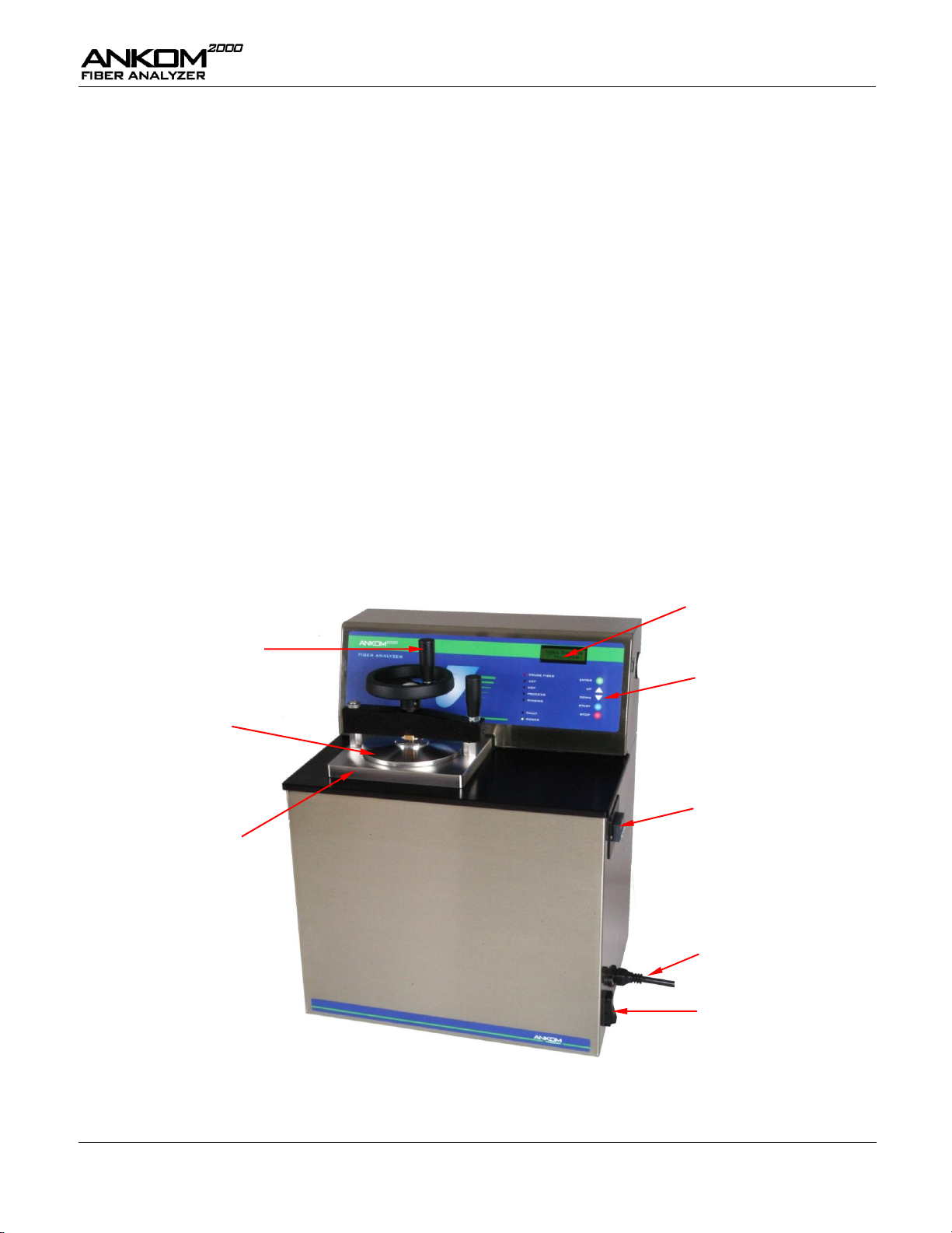
Keypad
Display
Vessel Lid
Vessel
Vessel Clamp Handle
Temperature Controller
Power Cord
Power Switch
Instrument Description
General Description
The ANKOM
Neutral Detergent Fiber (NDF), and Crude Fiber within food and/or feed samples. Enabled by Filter Bag
Technology, up to 24 samples can be processed at one time.
During analysis cell contents are removed as the encapsulated sample is subjected to the appropriate chemical (AD,
ND, or crude fiber acid and base) solutions, leaving the desired fiber fraction. Results are determined
gravimetrically. The filter bags are designed to allow proper flow of solutions while retaining non-soluble
components. The fiber residue captured in the filter bag can be used for follow-on assays such as ADIN, NDIN, and
ADL.
2000
Fiber Analyzer is designed to efficiently and accurately determine Acid Detergent Fiber (ADF),
Like the ANKOM
200
Fiber Analyzer, digestion and rinse operations are all performed within the same instrument,
allowing for the elimination of the separate filtration step. Process temperatures are precisely controlled while
providing proper agitation to ensure a uniform flow of chemical solutions and rinses across each sample.
Below are detailed views of the ANKOM
2000
Fiber Analyzer.
Rev E 1/14/15 pg. 7
Page 8
Operator’s Manual
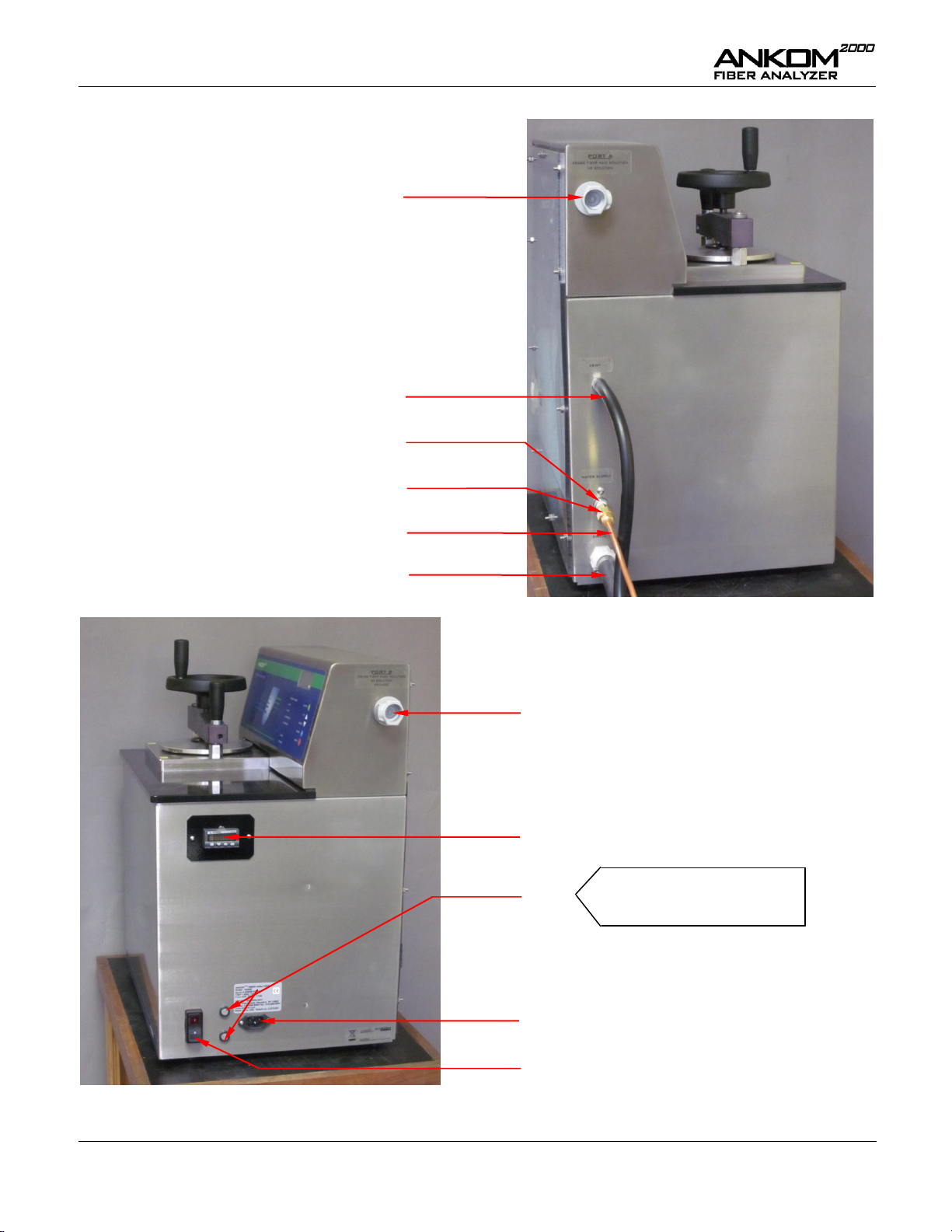
Power Switch
Port B – Used for Crude Fiber Base solution, AD
solution, and Diluted Amylase
Power Cord Inlet
Temperature Controller
Port A – Used for Crude Fiber
Acid solution and ND solution
Fuses
Vent Tube
Line to Hot Water Supply
Drain Hose
Water Filter
Left Side View
Right Side View
Water Supply Fitting
Domestic: 15A/120V
International: 10A/220V
pg. 8 Rev E 1/14/15
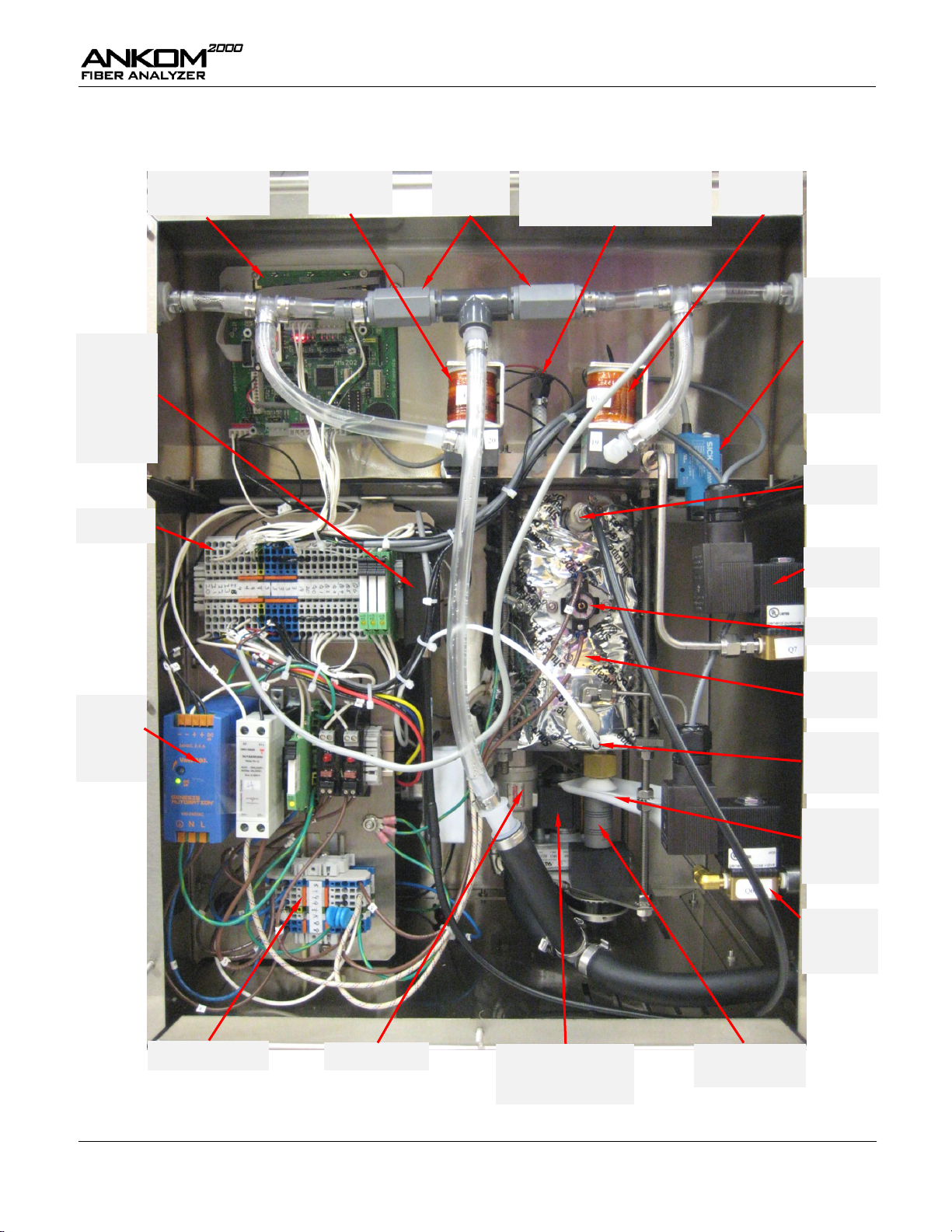
Page 9
Operator’s Manual
A2000 Computer
(part # A09)
Check Valve
Assembly
Pressure Transducer (part # 6121)
&
Fitting Assembly (part # A25)
Valve B
(part # A19 B)
SICK Fiber
Optic
Module - for
Instruments
delivered
before 4/09
(part # A18)
Vent Valve
(part # A22)
24 VDC
Power
Supply
(part # 963)
High Voltage DIN Rail
Drain Valve
Level Sensor
Fitting
ETS Switch
Water
Supply Valve
(part # A21)
Maintenance
Alert
Collector
(part # F27)
Motor Coupler
(part # 632)
24V DIN Rail
Motor
(part # A08 – 120/60)
(part # A10 – 220/50)
Digestion
Vessel
Temperature
Probe
(part # A17)
Analog Level
Sensor
Module - for
Instruments
delivered
after 4/09
(part # A31)
Valve A
(part # A19 A)
Internal Components
Rev E 1/14/15 pg. 9
Page 10
Operator’s Manual
Hazardous Pressure – Do NOT open the Vessel Lid during operation. The
contents of the Vessel are hot and under pressure. Failure to observe this
caution may result in scalding or burning.
Hot Surfaces – Do NOT touch the Vessel surfaces during operation. The surface
can exceed 70°C (158°F). Failure to observe this caution may result in
burning.
Hazardous Voltages – Do NOT operate the instrument with the cover removed.
Hazardous voltages are present during operation. The Power Cord must be
disconnected prior to removal of the rear panel. Failure to observe this caution
may result in electrical shock or electrocution.
Hazardous Materials – Caution should be used when handling hot effluent that
may be caustic or corrosive. If necessary, the solution can be collected in a
container and neutralized before disposal. Follow safe laboratory practices
according to your local regulations when installing and using this instrument and
associated chemicals.
WARNING: Attempts to override safety features or to use this instrument in a
manner not specified by ANKOM Technology voids the warranty and may result
in serious injury or even death.
This system is designed to meet and/or exceed the applicable standards of
CE, CSA, NRTL and OSHA.
IMPORTANT
The Power Switch must be in the OFF position before plugging the instrument Power
Cord into the power source.
In the event of an instrument malfunction, the internal heater will be automatically
turned off by one of the following safety devices:
1) Electrical Fuses
2) The Emergency Temperature Shut-off Switch (ETS)
3) The Pressure Transducer
Do NOT open the Vessel Lid during or after an operation until both pressure and
liquid are thoroughly exhausted. Connect and secure the Drain Hose along the path to
the drain so it will not move when hot pressurized fluid is exhausted. Failure to
secure the hose could result in uncontrolled chemical flow.
Please review the entire contents of this manual before you begin operating this
instrument.
Safety Precautions
pg. 10 Rev E 1/14/15
Page 11
Operator’s Manual
1.
Remove the instrument from the shipping container and place it in an area that is within six feet of a
drain and water supply on a surface that is firm and level. The instrument must not be subject to
excessive shock, vibration, dirt, moisture, oil, or other fluids.
IMPORTANT
Do NOT place this instrument near microwave ovens or mechanical devices.
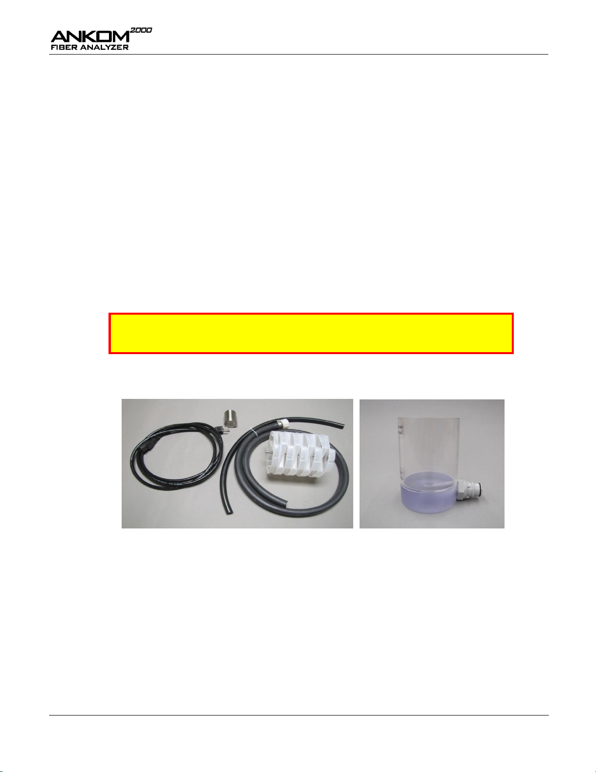
Your instrument comes complete with a Power Cord, a Drain Hose, a Vent Tube, a Bag Suspender
Assembly (including Bag Suspender Trays and a Bag Suspender Weight), and an Amylase Container.
2.
With the Power Switch in the OFF position, plug the Power Cord into the Power Cord Inlet.
3.
Plug the Power Cord into the power source.
4.
Install the Water Filter assembly. Attach ¼” copper tubing to the hot water source (+50°C Crude Fiber,
+70°C ND and AD) and to the Water Supply Fitting located on the left side of the instrument.
5.
Connect and secure the Drain Hose so that it will not move when hot pressurized fluid is exhausted.
Instrument Installation
Site Requirements
To install and operate the ANKOM
Adjustable wrench
Water supply located close to the ANKOM
70°C for ADF/NDF analyses
Adequate power (see “Operating Environment” section)
Drain
Instrument Installation Procedure
To install the ANKOM
2000
Fiber Analyzer, follow the procedure detailed below.
2000
Fiber Analyzer you will need the following:
2000
capable of heating water to 50°C for Crude Fiber and
Rev E 1/14/15 pg. 11
Page 12
Operator’s Manual
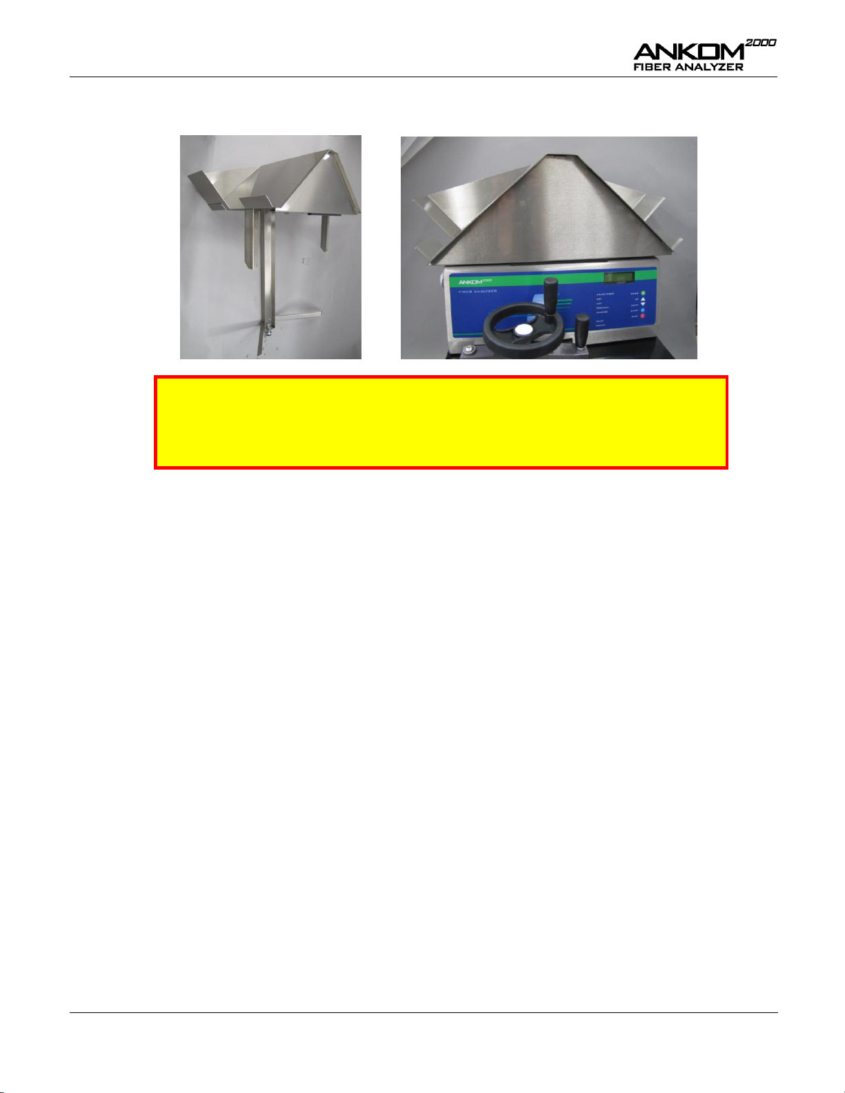
6.
If you are using Cubetainers for your chemicals, install the Cubetainer Shelf shown below (Optional).
IMPORTANT
The solutions are gravity fed into the instrument ports. The bottom of the solution level
must be at least 5” (13cm) above the port. The top of the solution level can be no more
than 20” (50cm) above either port or the solution will overflow into the drain.
pg. 12 Rev E 1/14/15
Page 13
Operator’s Manual
Item
Recommended Product
Electronic Balance with four-place readout
ANKOM #TB Balance Hardware
ANKOM #TBS Balance Software
Filter Bags
ANKOM #F57
Bag Holder (used for adding sample to an empty filter bag)
ANKOM #101.2
Heat Sealer for sealing the filter bags
ANKOM #1915 (120V), #1920 (220V)
Solvent Resistant Marker
ANKOM #F08
Desiccant Pouch
ANKOM #X45
Oven for drying (capable of maintaining 102°C ± 2°)
ANKOM #RD (120V), #RDI (220V)
Sample
-----------------
Spoon
-----------------
Fiber Analysis Support Items
The following support items are needed to perform the fiber analysis procedures:
Analysis Options using the ANKOM
The ANKOM
will run with default digestion and rinse time settings unless you select the Custom analysis option. This option
allows you to do ADF, NDF, or Crude Fiber analyses using custom digestion and rinse time settings.
For maintenance purposes, the ANKOM
The following sections provide the information you will need to use and maintain the ANKOM
2000
Fiber Analyzer can be configured to run ADF, NDF, and Crude Fiber analyses. The instrument
2000
also provides the capability to flush the solution lines.
Fiber Analyzer
2000
Fiber Analyzer.
2000
Rev E 1/14/15 pg. 13
Page 14

Operator’s Manual
This page intentionally left blank
pg. 14 Rev E 1/14/15
Page 15
Operator’s Manual
ADF contained within a food or feed sample can be calculated using the following formula:
% ADF (as-received basis)
=
100 x (W3 – (W1 x C1))
W2
Where:
W1 = Bag tare weight
W2 = Sample weight
W3 = Dried weight of filter bag with fiber after extraction process
C1 = Blank bag correction (running average of final oven-dried weight
divided by original blank bag weight)
To prepare samples for fiber analysis, follow the procedure detailed below.
IMPORTANT
When using the ANKOM
2000
Fiber Analyzer for ADF analysis, at least one blank filter bag
should be included with the sample set as an indicator of particle loss. A running average
of the blank bag weights is used in the fiber calculation as the C1 correction factor. A C1
value larger than 1.0000 indicates that sample particles were lost from filter bags and
deposited on the blank bag. Any fiber particle loss from the filter bags will generate
erroneous results. If particle loss is observed, the grinding method for the specific sample
should be evaluated.
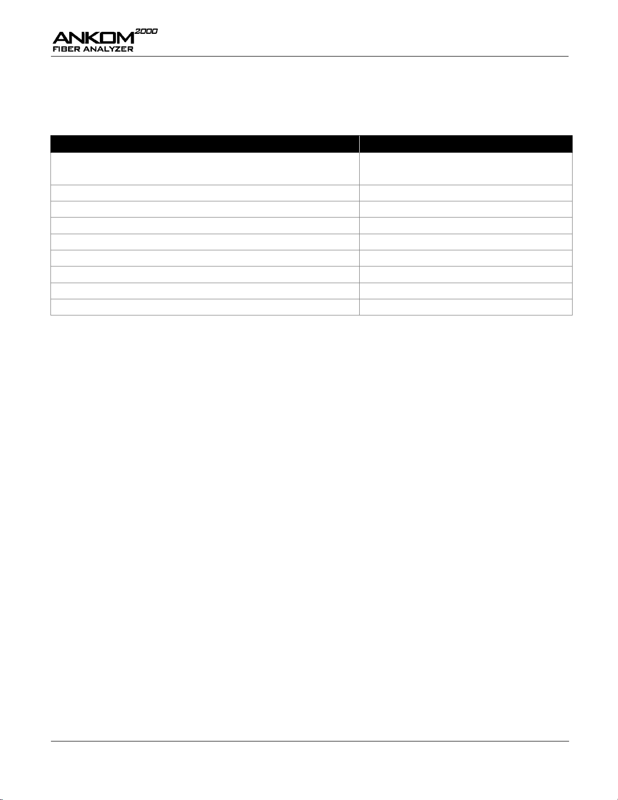
1.
Using a Solvent Resistant Marker, number all of the filter bags you will use
during the fiber analysis.
2.
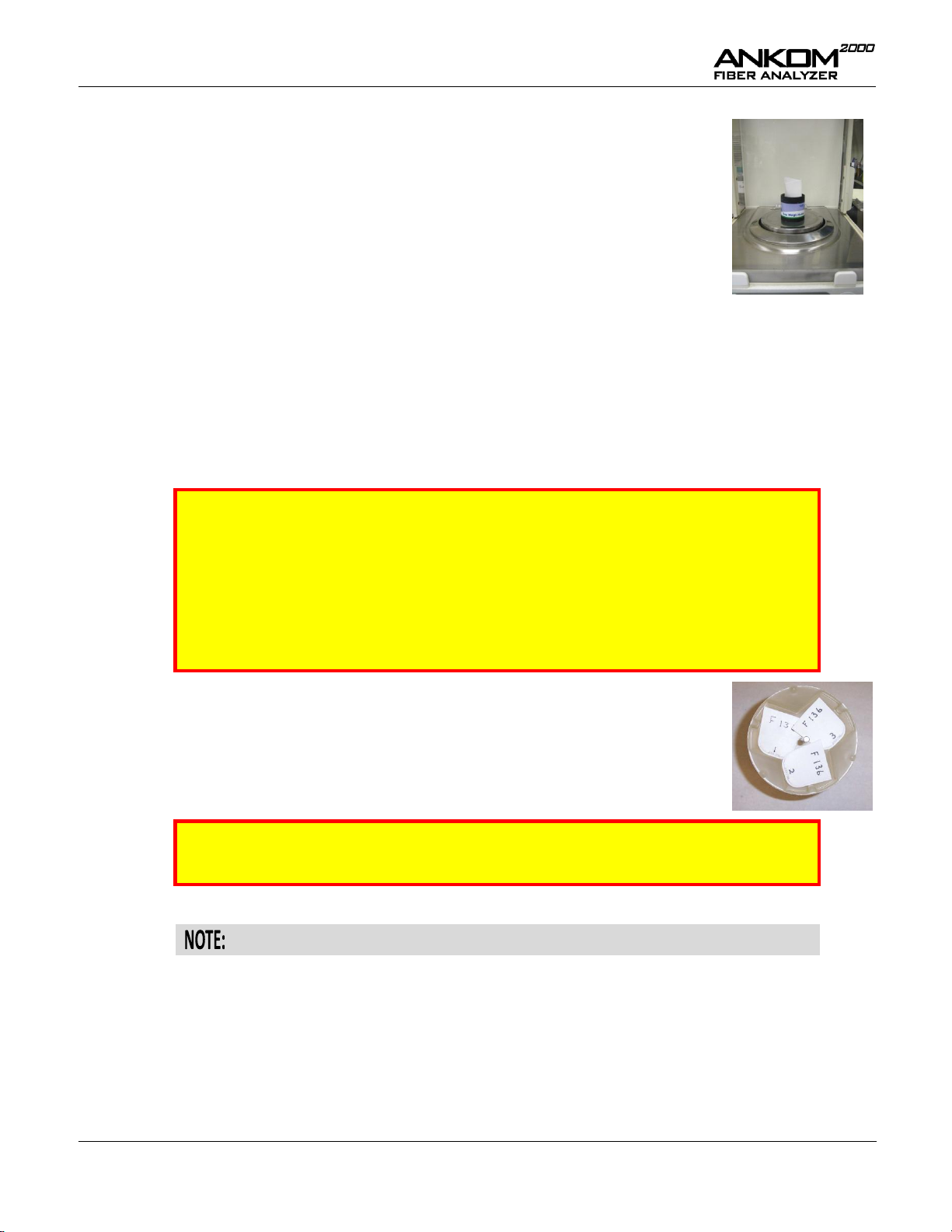
Weigh and record the weight of each empty filter bag (W1).
3.
Set the Heat Sealer dial to between 4 and 5. (The setting may vary from sealer to
sealer.)
4.
Seal at least one empty filter bag (to be used as a blank)
within 4mm of its open end. Keep the sealer arm down for 2
– 3 seconds after the red sealer light turns off (to cool the
seal). The seal can be seen as a solid melted stripe along the
top edge of the filter bag (as shown to the right). If the seal
is not strong, re-seal the bag.
Seal
ADF Analysis
ADF Calculation
ADF Sample Preparation Procedure
Rev E 1/14/15 pg. 15
Page 16
Operator’s Manual
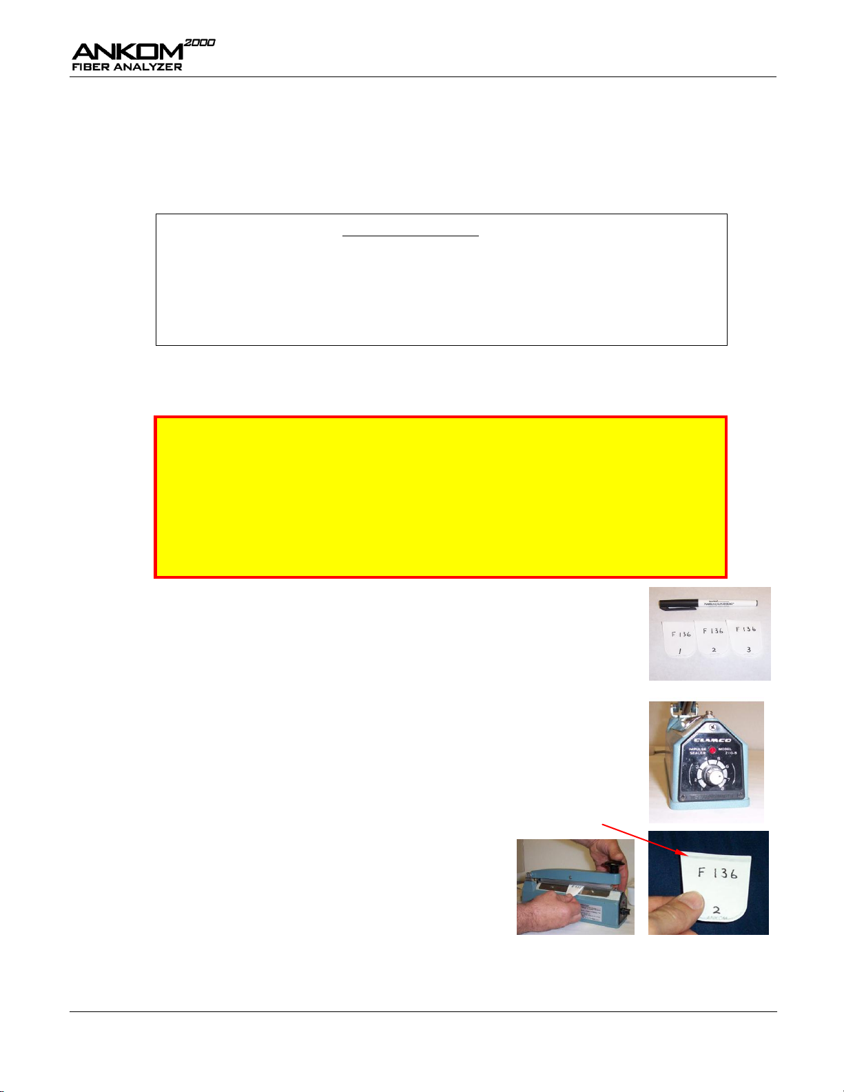
5.
Place an empty filter bag in the Bag Holder in an open position.
6.
Tare the weight of the empty filter bag and the holder together.
7.
Add 0.45 – 0.50g of sample to the filter bag. Keep all particles away from the
sealing area of the filter bag.
8.
Record the weight of the sample (W2) and tare.
9.
Seal the filter bag within 4mm of its open end. Keep the sealer arm down for 2 – 3 seconds after the red
sealer light turns off (to cool the seal). The seal can be seen as a solid melted stripe along the top edge of
the filter bag. If the seal is not strong, re-seal the bag.
10.
Spread the sample out uniformly within the filter bag by shaking and flicking the bag to eliminate
clumping.
11.
Repeat steps 5 – 10 for all filter bags that will be used in the Analyzer. (Up to 24 bags can be processed
during one procedure.)
IMPORTANT
If your samples contain soybean products or >5% fat, before doing the ADF analysis in
the ANKOM
2000
, you will need to do a pre-extraction. For samples containing non-roasted
soybean or >5% fat, follow the pre-extraction steps below:
1. Place the filter bags with sample (up to 23) into a container with a top.
2. Pour enough fresh acetone into the container to cover the bags.
3. Put the top on the container.
4. Shake the container 10 times and allow bags to soak for 10 minutes.
5. Pour out and dispose of the acetone.
6. Execute steps 1 through 5 a total of two times.
7. Place the bags on a wire screen to air-dry.
If your samples contain roasted soybean, follow the pre-extraction steps below:
1. Place the filter bags with sample (up to 23) into a container with a top.
2. Pour enough fresh acetone into the container to cover the bags.
3. Put the top on the container.
4. Shake the container 10 times.
5. Pour out and dispose of the acetone.
6. Pour fresh acetone into the container and allow the samples to soak for twelve
hours.
7. Pour out the acetone.
8. Place the bags on a wire screen to air-dry.
12.
Place the filter bags with sample and at least one empty bag (used as a Blank) into
the Bag Suspender trays as shown (maximum of three bags per tray).
13.
Stack each tray on the Bag Suspender rod (eight trays in total) with each tray
rotated 120 degrees from the tray below.
IMPORTANT
You must use all eight trays even if they are empty.
14.
Add the 9th tray to the top of the Bag Suspender rod. This tray contains no filter bags and acts as a cover.
The samples are now ready for the ADF analysis procedure.
pg. 16 Rev E 1/14/15
Page 17

Operator’s Manual
IMPORTANT
If you are changing from one analysis type to another, flush the system before running. See
the “Flush Procedure” section of this manual for more information.
1.
Verify that the hot water supply is on and the drain hose is securely positioned in the drain.
2.
If you are using Cubetainers for your chemicals, attach the AD solution
hose first to the Cubetainer and then to Port B on the instrument.
IMPORTANT
The solutions are gravity fed into the instrument ports. The bottom of the solution level
must be at least 5” (13cm) above the port. The top of the solution level can be no more
than 20” (50cm) above either port or the solution will overflow into the drain.
3.
Open the Vessel Lid.
4.
Place the bag suspender with the samples into the Vessel.
5.
Place the Bag Suspender Weight onto the Bag Suspender rod to hold the trays in place.
6.
Turn the instrument Power Switch to the ON position. The Display will light and allow you to select an
analysis procedure.
7.
Press the arrow keys on the Keypad until you see “Select ADF” on the
Display.
Select ADF
v <Enter>
IMPORTANT
The ADF analysis will use the following default settings:
60 minute digestion
four 5 minute rinses
If you want to run a custom ADF analysis that allows you to set the digestion time and the
number of rinses, press the arrow keys until you see “Select Custom” on the Display.
ADF Analysis Procedure using the ANKOM
2000
Fiber Analyzer
To perform ADF analysis on prepared samples, follow the procedure detailed below.
Rev E 1/14/15 pg. 17
Page 18

Operator’s Manual
8.
Press ENTER on the Keypad and follow the prompts on the Display to set up the instrument for ADF
analysis.
9.
Close the Vessel Lid and tighten it by turning the Vessel Clamp Handle.
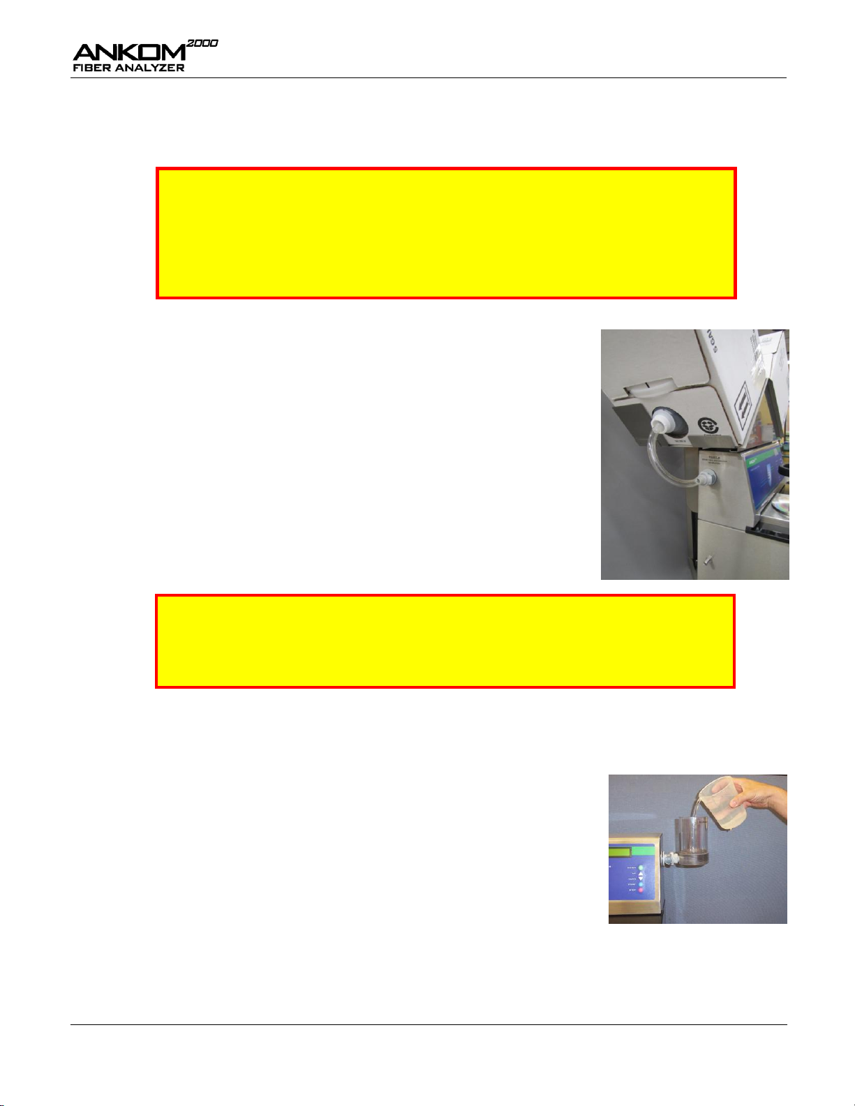
If you do not want to use the Cubetainers to automatically add your solutions, you
can manually fill the vessel for each procedure. First make sure that the hoses to
the Cubetainers are disconnected. Then press START on the Keypad and
immediately pour 2L of solution directly into the vessel. Please note that the
solution must cover the level sensor in order for the instrument to start its
operation.
10.
Press START on the Keypad. Solution from the Cubetainer will flow into the vessel through Port B.
Once the analysis begins, digestions and rinses occur automatically, with the
analyzer Display providing information about the process time remaining, the
temperature, and the pressure. Pressing STOP on the Keypad at any time during
the analysis ends the operation and opens the drain to exhaust the solution.
11.
When the “Process Complete” message appears on the Display, the analyzer operation is complete.
Open the Vessel Lid and remove the Samples at this time.
12.
Gently press out excess water from the bags.
13.
Place bags in a 250ml beaker and add enough acetone to cover them. Let the bags soak in acetone for
3 – 5 minutes.
14.
Remove the bags from the acetone and place them on a wire screen to air-dry.
IMPORTANT
Do NOT place bags in the oven until the acetone has completely evaporated.
15.
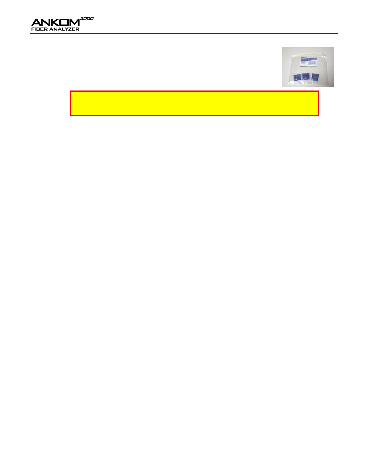
Place air-dried bags in the oven and heat at 102°C ± 2° for 2 – 4 hours (depending on the oven).
16.
Remove the samples from the oven and place them in a Desiccant Pouch.
IMPORTANT
Do NOT use conventional countertop or cabinet desiccators for this analysis.
17.
Allow the samples to cool to room temperature. This should take about 10 – 15 minutes.
18.
Remove one filter bag from the Desiccant Pouch. Press the pouch to remove ambient air and zip it tight.
19.
Re-weigh the filter bag (W3) immediately.
20.
Repeat steps 18 and 19 for each filter bag in the Desiccant Pouch.
pg. 18 Rev E 1/14/15
Page 19

Operator’s Manual
NDF contained within a food or feed sample can be calculated using the following formula:
% NDF (as-received basis)
=
100 x (W3 – (W1 x C1))
W2
Where:
W1 = Bag tare weight
W2 = Sample weight
W3 = Dried weight of filter bag with fiber after extraction process
C1 = Blank bag correction (running average of final oven-dried weight
divided by original blank bag weight)
To prepare samples for fiber analysis, follow the procedure detailed below.
IMPORTANT
When using the ANKOM
2000
Fiber Analyzer for NDF analysis, at least one blank filter bag
should be included with the sample set as an indicator of particle loss. A running average
of the blank bag weights is used in the fiber calculation as the C1 correction factor. A C1
value larger than 1.0000 indicates that sample particles were lost from filter bags and
deposited on the blank bag(s). Any fiber particle loss from the filter bags will generate
erroneous results. If particle loss is observed, the grinding method should be evaluated.
1.
Using a Solvent Resistant Marker, number all of the filter bags you will use
during the fiber analysis.
2.
Weigh and record the weight of each empty filter bag (W1).
3.
Set the Heat Sealer dial to between 4 and 5. (The setting may vary from sealer to
sealer.)
4.
Seal at least one empty filter bag (to be used as a blank)
within 4mm of its open end. Keep the sealer arm down for 2
– 3 seconds after the red sealer light turns off (to cool the
seal). The seal can be seen as a solid melted stripe along the
top edge of the filter bag (as shown to the right). If the seal
is not strong, re-seal the bag.
Seal
NDF Analysis
NDF Calculation
NDF Sample Preparation Procedure
Rev E 1/14/15 pg. 19
Page 20

Operator’s Manual
5.
Place an empty filter bag in the Bag Holder in an open position.
6.
Tare the weight of the empty filter bag and the holder together.
7.
Add 0.45 – 0.50g of sample to the filter bag. Keep all particles away from the
sealing area of the filter bag.
8.
Record the weight of the sample (W2) and tare.
9.
Seal the filter bag within 4mm of its open end. Keep the sealer arm down for 2 – 3 seconds after the red
sealer light turns off (to cool the seal). The seal can be seen as a solid melted stripe along the top edge of
the filter bag. If the seal is not strong, re-seal the bag.
10.
Spread the sample out uniformly within the filter bag by shaking and flicking the bag to eliminate
clumping.
11.
Repeat steps 5 – 10 for all filter bags that will be used in the Analyzer. (Up to 24 bags can be processed
during one procedure.)
IMPORTANT
If your samples contain soybean products or >5% fat, before doing the NDF analysis in
the ANKOM
2000
, you will need to do a pre-extraction. For samples containing non-roasted
soybean or >5% fat, follow the pre-extraction steps below:
1. Place the filter bags with sample (up to 23) into a container with a top.
2. Pour enough fresh acetone into the container to cover the bags.
3. Put the top on the container.
4. Shake the container 10 times and allow bags to soak for 10 minutes.
5. Pour out and dispose of the acetone.
6. Execute steps 1 through 5 a total of two times.
7. Place the bags on a wire screen to air-dry.
If your samples contain roasted soybean, follow the pre-extraction steps below:
1. Place the filter bags with sample (up to 23) into a container with a top.
2. Pour enough fresh acetone into the container to cover the bags.
3. Put the top on the container.
4. Shake the container 10 times.
5. Pour out and dispose of the acetone.
6. Pour fresh acetone into the container and allow the samples to soak for twelve
hours.
7. Pour out the acetone.
8. Place the bags on a wire screen to air-dry.
12.
Place the filter bags with sample and at least one empty bag (used as a Blank) into
the Bag Suspender trays as shown (maximum of three bags per tray).
13.
Stack each tray on the Bag Suspender rod (eight trays in total) with each tray
rotated 120 degrees from the tray below.
IMPORTANT
You must use all eight trays even if they are empty.
14.
Add the 9th tray to the top of the Bag Suspender rod. This tray contains no filter bags and acts as a cover.
The samples are now ready for the NDF analysis procedure.
pg. 20 Rev E 1/14/15
Page 21
Operator’s Manual
IMPORTANT
If you are changing from one analytical method to another, flush the system before
running. See the “Flush Procedure” section of this manual for more information.
Amylase tends to be sticky. You should always clean the Amylase Dispenser
Assembly and flush Port B after every NDF procedure unless you are running another
NDF procedure with less than two hours between procedures.
1.
Verify that the hot water supply is on and the drain hose is securely positioned in the drain.
2.
If you are using Cubetainers for your chemicals, attach the ND solution
hose first to the Cubetainer and then to Port A on the instrument.
IMPORTANT
The solutions are gravity fed into the instrument ports. The bottom of the solution level
must be at least 5” (13cm) above the port. The top of the solution level can be no more
than 20” (50cm) above either port or the solution will overflow into the drain.
3.
Open the Vessel Lid.
4.
Place the bag suspender with the samples into the Vessel.
5.
Place the Bag Suspender Weight onto the Bag Suspender rod to hold the trays in place.
6.
Attach the Amylase Dispenser Assembly to Port B. This will be used to
automatically add amylase to the vessel during the rinses.
7.
Fill half of the dispenser with water.
8.
Add two capfuls (8ml) of amylase to the dispenser.
9.
Fill the dispenser with water.
10.
Turn the instrument Power Switch to the ON position. The Display will light and allow you to select an
analysis procedure.
NDF Analysis Procedure using the ANKOM
2000
Fiber Analyzer
To perform NDF analysis on prepared samples, follow the procedure detailed below.
Rev E 1/14/15 pg. 21
Page 22

Operator’s Manual
11.
Press the arrow keys on the Keypad until you see “Select NDF” on the
Display.
Select NDF
v <Enter>
IMPORTANT
The NDF analysis will use the following default settings:
75 minute digestion
four 5 minute rinses
If you want to run a custom NDF analysis that allows you to set the digestion time and the
number of rinses, press the arrow keys until you see “Select Custom” on the Display.
12.
Press ENTER on the Keypad and follow the prompts on the Display to set up the instrument for NDF
analysis.
If you do not want to use the Cubetainers to automatically add your solutions, you
can manually fill the vessel for each procedure. First make sure that the hoses to
the Cubetainers are disconnected. Then press START on the Keypad and
immediately pour 2L of solution directly into the vessel. Please note that the
solution must cover the level sensor in order for the instrument to start its
operation.
13.
Press START on the Keypad. Solution from the Cubetainer will flow into the vessel through Port A.
Once the analysis begins, digestions and rinses occur automatically, with the
analyzer Display providing information about the process time remaining, the
temperature, and the pressure. Pressing STOP on the Keypad at any time during
the analysis ends the operation and opens the drain to exhaust the solution.
14.
After the ND solution has been automatically inserted and agitation begins, manually add 20g of Na2SO3
and 4.0ml of alpha-amylase directly into the Vessel.
15.
Close the Vessel Lid and tighten it by turning the Vessel Clamp Handle.
16.
When the “Process Complete” message appears on the Display, the analyzer operation is complete.
Open the Vessel Lid and remove the Samples at this time.
17.
Gently press out excess water from the bags.
18.
Place bags in a 250ml beaker and add enough acetone to cover them. Let the bags soak in acetone for
3 – 5 minutes.
19.
Remove the bags from the acetone and place them on a wire screen to air-dry.
pg. 22 Rev E 1/14/15
Page 23

Operator’s Manual
IMPORTANT
Do NOT place bags in the oven until the acetone has completely evaporated.
20.
Place air-dried bags in the oven and heat at 102°C ± 2° for 2 – 4 hours (depending on the oven).
21.
Remove the samples from the oven and place them in a Desiccant Pouch.
IMPORTANT
Do NOT use conventional countertop or cabinet desiccators for this analysis.
22.
Allow the samples to cool to room temperature. This should take about 10 – 15 minutes.
23.
Remove one filter bag from the Desiccant Pouch. Press the pouch to remove ambient air and zip it tight.
24.
Re-weigh the filter bag (W3) immediately.
25.
Repeat steps 23 and 24 for each filter bag in the Desiccant Pouch.
IMPORTANT
Amylase is sticky. Unless you are running multiple NDF procedures in near succession,
you must flush the system after NDF procedures. See the “Flush Procedure” section of this
manual for details.
Rev E 1/14/15 pg. 23
Page 24

Operator’s Manual
This page intentionally left blank
pg. 24 Rev E 1/14/15
Page 25

Operator’s Manual
Crude Fiber contained within a food or feed sample can be calculated using the following formula:
% Crude Fiber
=
100 x (W3 – (W1 x C1))
W2
Where:
W1 = Bag tare weight
W2 = Sample weight
W3 = Weight of Organic Matter (loss of weight on ignition of bag and fiber)
C1 = Ash corrected blank bag factor (running average of loss of weight on
ignition of blank bag / original blank bag)
To prepare samples for fiber analysis, follow the procedure detailed below.
IMPORTANT
When using the ANKOM
2000
Fiber Analyzer for Crude Fiber analysis, at least one blank
filter bag should be included with the sample set as an indicator of particle loss. A running
average of the blank bag weights is used in the fiber calculation as the C1 correction factor.
A C1 value larger than 1.0000 indicates that sample particles were lost from filter bags and
deposited on the blank bag(s). Any fiber particle loss from the filter bags will generate
erroneous results. If particle loss is observed, the grinding method should be evaluated.
1.
Using a Solvent Resistant Marker, number all of the filter bags you will use
during the fiber analysis.
2.
Weigh and record the weight of each empty filter bag (W1).
3.
Set the Heat Sealer dial to between 4 and 5. (The setting may vary from sealer to
sealer.)
4.
Seal at least one empty filter bag (to be used as a blank)
within 4mm of its open end. Keep the sealer arm down for 2
– 3 seconds after the red sealer light turns off (to cool the
seal). The seal can be seen as a solid melted stripe along the
top edge of the filter bag (as shown to the right). If the seal
is not strong, re-seal the bag.
Seal
Crude Fiber Analysis
Crude Fiber Calculation
Crude Fiber Sample Preparation Procedure
Rev E 1/14/15 pg. 25
Page 26
Operator’s Manual
5.
Place an empty filter bag in the Bag Holder in an open position.
6.
Tare the weight of the empty filter bag and the holder together.
7.
Add 0.95 – 1.00g of sample to the filter bag. Keep all particles away from the
sealing area of the filter bag.
8.
Record the weight of the sample (W2) and tare.
9.
Seal the filter bag within 4mm of its open end. Keep the sealer arm down for 2 – 3 seconds after the red
sealer light turns off (to cool the seal). The seal can be seen as a solid melted stripe along the top edge of
the filter bag. If the seal is not strong, re-seal the bag.
10.
Spread the sample out uniformly within the filter bag by shaking and flicking the bag to eliminate
clumping.
11.
Repeat steps 5 – 10 for all filter bags that will be used in the Analyzer. (Up to 24 bags can be processed
during one procedure.)
IMPORTANT
For all samples you will need to do a pre-extraction of fat before doing a Crude Fiber
analysis in the ANKOM
2000
. Follow the pre-extraction steps below:
1. Place the filter bags with sample into a 250ml container.
2. Pour enough petroleum ether into the container to cover the bags.
3. Allow the bags to soak for 10 minutes.
4. Pour out and dispose of the petroleum ether.
5. Place the bags on a wire screen to air-dry.
12.
Place the filter bags with sample and at least one empty bag (used as a Blank) into
the Bag Suspender trays as shown (maximum of three bags per tray).
13.
Stack each tray on the Bag Suspender rod (eight trays in total) with each tray
rotated 120 degrees from the tray below.
IMPORTANT
You must use all eight trays even if they are empty.
14.
Add the 9th tray to the top of the Bag Suspender rod. This tray contains no filter bags and acts as a cover.
The samples are now ready for the Crude Fiber analysis procedure.
pg. 26 Rev E 1/14/15
Page 27

Operator’s Manual
1.
Verify that the hot water supply is on and the drain hose is securely positioned in the drain.
2.
Attach each Cubetainer hose first to the Cubetainer and then
to its specific chemical port. Port A is used for Crude Fiber
Acid solution. Port B is used for Crude Fiber Base solution.
IMPORTANT
The solutions are gravity fed into the instrument ports. The bottom of the solution level
must be at least 5” (13cm) above the port. The top of the solution level can be no more
than 20” (50cm) above either port or the solution will overflow into the drain.
3.
Open the Vessel Lid.
4.
Place the bag suspender with the samples into the Vessel.
5.
Place the Bag Suspender Weight onto the Bag Suspender rod to hold the trays in place.
6.
Turn the instrument’s Power Switch to the ON position. The Display will light and allow you to select an
analysis procedure.
IMPORTANT
If you are changing from one analytical method to another, flush the system before
running. See the “Flush Procedure” section of this manual for more information.
7.
Press the arrow keys on the Keypad until you see “Select Crude Fib”
on the Display.
Select Crude Fib
v <Enter>
Crude Fiber Analysis Procedure using the ANKOM
2000
Fiber Analyzer
To perform Crude Fiber analysis on prepared samples, follow the procedure detailed below.
Rev E 1/14/15 pg. 27
Page 28

Operator’s Manual
IMPORTANT
The Crude Fiber analysis will use the following settings:
40 minute Acid Digestion
40 minute Base digestion
two 5 minute Acid rinses
three 5 minute Base rinses
If you want to run a custom Crude Fiber analysis that allows you to set the digestion times
and the number of rinse cycles, press the arrow keys until you see “Select Custom” on the
Display.
8.
Press ENTER on the Keypad and follow the prompts on the Display to set up the instrument for Crude
Fiber analysis.
9.
Close the Vessel Lid tightening it by turning the Vessel Clamp Handle.
10.
Press START on the Keypad. Solution will flow first into the vessel through Port A.
Once the analysis begins, digestions and rinses occur automatically, with the
analyzer Display providing information about the process time remaining, the
temperature, and the pressure. Pressing STOP on the Keypad at any time during
the analysis ends the operation and opens the drain to exhaust the solution.
11.
When the “Process Complete” message appears on the Display, the analyzer operation is complete.
Open the Vessel Lid and remove the Samples at this time.
12.
Gently press out excess water from the bags.
13.
Place bags in a 250ml beaker and add enough acetone to cover them. Let the bags soak in acetone for
3 – 5 minutes.
14.
Remove the bags from the acetone and place them on a wire screen to air-dry.
IMPORTANT
Do NOT place bags in the oven until the acetone has completely evaporated.
15.
Place air-dried bags in the oven and heat at 102°C ± 2° for 2 – 4 hours (depending on the oven).
pg. 28 Rev E 1/14/15
Page 29
Operator’s Manual
16.
Remove the samples from the oven and place them in a Desiccant Pouch.
IMPORTANT
Do NOT use conventional countertop or cabinet desiccators for this part of the analysis.
17.
Allow the samples to cool to room temperature. This should take about 10 – 15 minutes.
18.
Re-weigh each filter bag immediately after removing from the Desiccant Pouch.
19.
Ash all filter bags in pre-weighed crucibles for 2 hours at 600°C ± 15°.
20.
Cool the ashed crucibles in a conventional desiccator.
21.
Weigh the ashed crucibles to calculate the loss of weight of organic matter (W3).
Rev E 1/14/15 pg. 29
Page 30

Operator’s Manual
This page intentionally left blank
pg. 30 Rev E 1/14/15
Page 31

Operator’s Manual
IMPORTANT
Amylase tends to be sticky. You should always clean the Amylase Dispenser Assembly
and flush Port B after every NDF procedure unless the next procedure you are running is
another NDF, and you run it within two hours of the previous procedure.
1.
Turn the instrument’s Power Switch to the ON position. The Display will light.
2.
Verify that the water supply is on and the drain hose is securely in the drain.
3.
Press the arrow keys on the Keypad until you see “Select Flush” on
the Display.
Select Flush
v <Enter>
4.
Press ENTER on the Keypad and follow the prompts on the Display
to set up the instrument for the Flush procedure.
5.
Attach the Amylase Dispenser Assembly to port B.
6.
Fill the dispenser with hot water.
7.
Attach the Amylase Dispenser Assembly to port A.
8.
Fill the dispenser with hot water.
If you press and hold the START key on the Keypad during the Flush operation,
water will flow into the Vessel. This will rinse the bottom of the Vessel, but it will
not rinse all the way to the top. If you need to rinse anything from the top part of
the inside of the Vessel, pour hot water into the Vessel as needed during the Flush
operation.
Flush Procedure
The Flush procedure allows you to clean the system with water. This procedure should be used when changing
from one procedure to another (e.g., when preparing to do an ADF analysis after completing an NDF analysis) or
when doing an NDF procedure after a previous NDF procedure with more than two hours between procedures, or
before storing the instrument.
To perform a Flush of your analyzer, follow the instructions below.
Rev E 1/14/15 pg. 31
Page 32

Operator’s Manual
This page intentionally left blank
pg. 32 Rev E 1/14/15
Page 33

Operator’s Manual
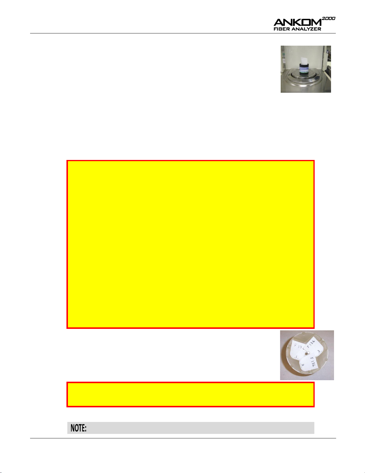
1.
Remove the back panel of the instrument.
2.
Inspect the Maintenance Alert Collector.
Rear View of instrument with cabinet back removed
3.
Clean any residue from the collector.
4.
Unscrew the filter body (the fixture on the
outside of the instrument that attaches to the
water supply).
5.
Unscrew and clean the metal filter screen.
6.
Reassemble the filter and compression fitting.
Make sure the valve body is tight and the
Teflon washer has not come out of the filter
body.
IMPORTANT
Do NOT insert the Bag Suspender into the instrument for this procedure.
7.
Press the arrow keys on the Keypad until you see “Select Flush” on the
Display. Press “ENTER” on the Keypad to turn the agitator on.
Select Flush
v <Enter>
8.
When the motor is activated, turn the Packing
Nut to the RIGHT until you hear a change in
the sound of the motor. (The motor will start to
labor as the packing nut gets harder to turn.)
9.
Loosen the Packing Nut slightly until the
motor stops laboring.
10.
Turn off the instrument and re-install the back
panel.
Packing Nut
Maintenance Alert Collector
Periodic Maintenance
Initial Maintenance (after 10 hours of operation)
After the first 10 hours of operation, follow the procedure below:
Rev E 1/14/15 pg. 33
Page 34

Operator’s Manual
1.
Turn off the instrument power and unplug the
Power Cord from the outlet.
2.
Using a flat blade screwdriver, twist the slot on
the fuse holders counterclockwise ¼ turn to
open.
3.
Check both fuses.
4.
Pull the fuse from the grey fuse cap and
replace as needed.
(120V – 15 amp / 220V – 10 amp)
Using a cotton swab with alcohol, wipe the tip of the
level sensor at least once per month if you use the
instrument daily.
Level Sensor
Fuses (2)
If you see a leak
If you see a leak, follow steps 6 – 9 in the Initial Maintenance procedure above.
Replacing the Fuses
To replace the fuses in the ANKOM
2000
Fiber Analyzer, follow the procedure detailed below.
Cleaning the Fiber Optic Level Sensor
pg. 34 Rev E 1/14/15
Page 35

Operator’s Manual
The agitation system and bag suspender should be checked every three to six months or if fiber values are higher
than normal or inconsistent.
IMPORTANT
Poor agitation will cause higher analysis values and poor repeatability.
To check the stroke of the agitation system, follow the procedure detailed below.
1. Place a full bag suspender in the Vessel (without
the bag suspender weight), but add NO water.
2. Remove the top from a dark felt tip marker.
3. Lay the marker horizontally on the top of the bag
suspender so that the tip touches the inside wall of
the Vessel.
4. With constant downward pressure on the marker,
hold the pen in place so that it rides the top tray up
and down as you execute the Flush Procedure.
(See the Flush Procedure section of this manual
for details.)
5. Allow the bag suspender (& pen) to move up and
down three or four times as the pen marks the
Vessel wall.
6. Stop the agitation.
7. Remove the pen and the bag suspender.
8. Measure the mark on the Vessel wall. It should be
½ inch long. If the motion is less than ½ inch, you
will need to replace either the Bag Suspender Tip
(see next page) or the agitator (because the old
disc has flattened).
To test the agitator vertical positioning, follow the procedure detailed below.
1. Place the bag suspender weight on the bag
suspender within the Vessel.
2. Place a straight edge across the top of the Vessel
as shown in the picture.
3. Run the Flush Procedure. (See the Flush
Procedure section of this manual for details.)
4. The weight should not hit the straight edge at the
top of the stroke. If the weight is hitting the lid or
traveling above the top of the Vessel, the agitator
has moved up in the Vessel and must be
completely re-seated at the bottom of the Vessel.
Contact ANKOM for assistance.
Check Agitation System and Bag Suspender
Rev E 1/14/15 pg. 35
Page 36

Operator’s Manual
Check Bag Suspender
The bag suspender should be checked every three to six months or if fiber values are higher than normal or
inconsistent.
Check the trays for melting.
The pictures shown are examples of extreme cases.
However, for proper operation you must replace trays
that show signs of melting or wear.
Check that the bottom tray is flat.
If the bottom tray is concave (see picture) the bag
suspender will catch in the vessel and melt.
Check the tip for excessive wear (see pictures).
Replace worn tips.
Melted trays
Concave
Tray
Good
Tip
Worn
Tip
Troubleshooting
The ANKOM technology web site has the most current troubleshooting information. Therefore, if you have any
questions about the operation of your ANKOM
pg. 36 Rev E 1/14/15
2000
Fiber Analyzer, please visit our web site at www.ankom.com.
Page 37

Operator’s Manual
Acid Detergent Fiber in Feeds - Filter Bag Technique (for A2000 and A2000I)
Definition
This method determines Acid Detergent Fiber, which is the residue remaining after digesting with H2SO4 and CTAB. The fiber residues are
predominantly cellulose and lignin.
Scope
This method is applicable to grains, feeds, forages, and all fiber-bearing material.
Apparatus
1. Analytical Balance—capable of weighing 0.1 mg.
2. Oven—capable of maintaining a temperature of 102 ± 2°C
(ANKOMRD Dryer, ANKOM Technology).
3. Digestion instrument—capable of performing the digestion at
100 ± 0.5°C and maintaining a pressure of 10-25psi. The
instrument must be capable of creating a similar flow around
each sample to ensure uniformity of extraction (ANKOM
2000
with 65rpm agitation, ANKOM Technology).
4. Filter Bags—constructed from chemically inert and heat resistant
filter media, capable of being heat sealed closed and able to
retain 25 micron particles while permitting solution penetration
(F57, ANKOM Technology).
5. Heat sealer—sufficient for sealing the filter bags closed to ensure
complete closure (1915, ANKOM Technology).
6. Desiccant Pouch—collapsible sealable pouch with desiccant
inside that enables the removal of air from around the filter bags
(MoistureStop weigh pouch, ANKOM Technology).
7. Marking pen—solvent and acid resistant (F08, ANKOM
Technology).
Reagents
1. Acid Detergent Solution—Add 20g cetyl trimethylammonium
bromide (CTAB) to 1L 1.00N H2SO4 previously standardized
(premixed chemical solution available from ANKOM). Agitate
and heat to aid solution.
CAUTION1: Sulfuric acid is a strong acid and will cause severe
burns. Protective clothing should be worn when working with
this acid. Always add acid to water and not the reverse.
CAUTION2: CTAB will irritate mucous membranes. A dust
mask and gloves should be worn when handling this chemical.
Sample Preparation
Grind samples in a centrifugal mill with a 2mm screen or cutter type
(Wiley) mill with a 1mm screen. Samples ground finer may have
particle loss from the filter bags and result in low values.
ADF Procedure (see the ADF Analysis section of the Operator’s
Manual for more detail)
1. Use a solvent resistant marker to label the filter bags to be
used in the analysis.
2. Weigh and record the weight of each empty filter bag (W1)
and zero the balance. NOTE: Do not pre-dry filter bags. Any
moisture will be accounted for by the blank bag correction.
3. Place 0.45 – 0.50g of prepared sample in up to 23 of the
bags and record the weight (W2) of each. Avoid placing the
sample in the upper 4mm of the bag.
4. Include at least one empty bag in the run to determine the
blank bag correction (C1). See Numbered Notes 1.
5. Using a heat sealer, completely seal each filter bag closed
within 4mm of the top to encapsulate the sample. NOTE:
Use sufficient heat to completely seal the filter bags and
allow enough cool time (2 sec) before removing each bag
from the heat sealer.
6. Pre-extract only samples containing soybean products or
>5% fat: Extract samples by placing 24 bags with samples
into a container with a top. Pour enough acetone into the
container to cover the bags and secure the top.
CAUTION3: Acetone is extremely flammable. Avoid static
electricity and use a fume hood when handling.
Shake the container 10 times and allow bags to soak for 10
minutes. Repeat with fresh acetone. Pour out acetone and
place bags on a wire screen to air-dry.
Exception – Roasted soybean: Due to the processing of
roasted soy a modification to the extraction is required.
Place roasted soy samples into a container with a top. Pour
enough acetone into the container to cover the bags and
secure the top. Shake the container 10 times and pour off the
acetone. Add fresh acetone and allow samples to soak for
twelve hours. After the soak time, pour out the acetone and
place the bags on a wire screen to air-dry.
7. Spread the sample uniformly inside the filter bags by
shaking and flicking the bags to eliminate clumping.
8. Place up to 3 bags on each of eight Bag Suspender Trays
(maximum of 24 bags). Stack the trays on the center post of
the Bag Suspender with each level rotated 120 degrees in
relation to the tray below it. Place the empty 9th tray on top.
NOTE: All nine trays must be used regardless of the number
of bags being processed.
9. Verify that the hot water supply is on and the drain hose is
securely positioned in the drain.
(Procedure continued on next page.)
Appendix A – ADF Method
Rev E 1/14/15 pg. 37
Page 38

Operator’s Manual
Calculations
% ADF (as-received basis)
=
100 x (W3 – (W1 x C1))
W2
Where:
W1 = Bag tare weight
W2 = Sample weight
W3 = Dried weight of bag with fiber after
extraction process
C1 = Blank bag correction (running
average of final oven-dried weight
divided by original blank bag
weight)
Numbered Notes
1. A running average blank bag correction factor (C1) should be
used in the calculation of fiber. The inclusion of at least one
blank bag in each run is mainly used as an indicator of particle
loss. A C1 larger than 1.0000 indicates that sample particles were
lost from filter bags and deposited on the blank bag during the
extraction. Any fiber particle loss from the filter bags will
generate erroneous results. If particle loss is observed then the
grinding method needs to be evaluated.
ADF Procedure (continued)
10. Read the Temperature Controller on the right side of the
instrument. If the temperature is higher than 20°C, cool the
Vessel as follows:
a. Fill the Vessel with cold water.
b. When the Temperature Controller reads 20°C, run
the Flush Procedure to drain the water.
11. If you are using Cubetainers for your chemicals, attach the
AD solution hose to the Cubetainer and then to Port B on the
instrument.
12. Open the Vessel Lid and insert the Bag Suspender with bags
into the Vessel and place the Bag Suspender Weight on top
of the empty 9th tray to keep the Bag Suspender submerged.
13. Follow the instructions on the ANKOM
2000
display:
a. Select ADF.
b. Close the Vessel Lid.
c. Confirm hot water is on (>70°C).
d. Press START.
14. When the ADF extraction and rinsing procedures are
complete, open the Vessel Lid and remove the filter bags.
Gently press out excess water from the bags. Place bags in a
250ml beaker and add enough acetone to cover bags and
soak for 3-5 minutes.
15. Remove the filter bags from the acetone and place them on a
wire screen to air-dry. Completely dry in an oven at 102 ±
2°C. (In most ovens the filter bags will be completely dry
within 2-4 hours.) NOTE: Do not place bags in the oven
until the acetone has completely evaporated.
16. Remove the filter bags from the oven and immediately place
them directly into a collapsible desiccant pouch and flatten
to remove any air. Cool to ambient temperature and weigh
the filter bags (W3). NOTE: Do not use a conventional
desiccator container.
pg. 38 Rev E 1/14/15
Page 39

Operator’s Manual
Neutral Detergent Fiber in Feeds - Filter Bag Technique (for A2000 and A2000I)
Definition
This method determines Neutral Detergent Fiber, which is the residue remaining after digesting in a detergent solution. The fiber residues are
predominantly hemicellulose, cellulose, and lignin.
Scope
This method is applicable to grains, feeds, forages, and all fiber-bearing material.
Apparatus
1. Analytical Balance—capable of weighing 0.1 mg.
2. Oven—capable of maintaining a temperature of 102 ± 2°C
(ANKOMRD Dryer, ANKOM Technology).
3. Digestion instrument—capable of performing the digestion at
100 ± 0.5°C and maintaining a pressure of 10-25psi. The
instrument must be capable of creating a similar flow around
each sample to ensure uniformity of extraction (ANKOM
2000
with 65rpm agitation, ANKOM Technology).
4. Filter Bags—constructed from chemically inert and heat resistant
filter media, capable of being heat sealed closed and able to
retain 25 micron particles while permitting solution penetration
(F57, ANKOM Technology).
5. Heat sealer—sufficient for sealing the filter bags closed to ensure
complete closure (1915, ANKOM Technology).
6. Desiccant Pouch—collapsible sealable pouch with desiccant
inside that enables the removal of air from around the filter bags
(MoistureStop weigh pouch, ANKOM Technology).
7. Marking pen—solvent and acid resistant (F08, ANKOM
Technology).
Reagents
1. Neutral Detergent Solution—Add 30g Sodium dodecyl sulfate
(USP), 18.61g Ethylenediaminetetraacetic disodium salt
(dehydrate), 6.81g Sodium borate, 4.56g Sodium phosphate
dibasic (anhydrous), and 10.0ml Triethylene glycol to 1L
distilled H2O (premixed chemical solution available from
ANKOM Technology). Check that pH is from 6.9 to 7.1. Agitate
and heat to aid solution.
CAUTION1: Powdered chemicals will irritate mucous
membranes. A dust mask and gloves should be worn when
handling these chemicals.
2. Alpha-amylase—Heat-stable bacterial alpha-amylase: activity =
17,400 Liquefon Units / ml (FAA, ANKOM Technology).
3. Sodium sulfite—Na2SO3, anhydrous (FSS, ANKOM
Technology)
Sample Preparation
Grind samples in a centrifugal mill with a 2mm screen or cutter type
(Wiley) mill with a 1mm screen. Samples ground finer may have
particle loss from the filter bags and result in low values.
NDF Procedure (see the NDF Analysis section of the Operator’s
Manual for more detail)
1. Use a solvent resistant marker to label the filter bags to be
used in the analysis.
2. Weigh and record the weight of each empty filter bag (W1)
and zero the balance. NOTE: Do not pre-dry filter bags. Any
moisture will be accounted for by the blank bag correction.
3. Place 0.45 – 0.50g of prepared sample in up to 23 of the
bags and record the weight (W2) of each. Avoid placing the
sample in the upper 4mm of the bag.
4. Include at least one empty bag in the run to determine the
blank bag correction (C1). See Numbered Notes 1.
5. Using a heat sealer, completely seal each filter bag closed
within 4mm of the top to encapsulate the sample. NOTE:
Use sufficient heat to completely seal the filter bags and
allow enough cool time (2 sec) before removing each bag
from the heat sealer.
6. Pre-extract only samples containing soybean products or
>5% fat: Extract samples by placing 24 bags with samples
into a container with a top. Pour enough acetone into the
container to cover the bags and secure the top.
CAUTION2: Acetone is extremely flammable. Avoid static
electricity and use a fume hood when handling.
Shake the container 10 times and allow bags to soak for 10
minutes. Repeat with fresh acetone. Pour out acetone and
place bags on a wire screen to air-dry.
Exception – Roasted soybean: Due to the processing of
roasted soy a modification to the extraction is required.
Place roasted soy samples into a container with a top. Pour
enough acetone into the container to cover the bags and
secure the top. Shake the container 10 times and pour off the
acetone. Add fresh acetone and allow samples to soak for
twelve hours. After the soak time, pour out the acetone and
place the bags on a wire screen to dry.
7. Spread the sample uniformly inside the filter bags by
shaking and flicking the bags to eliminate clumping.
8. Place up to 3 bags on each of eight Bag Suspender Trays
(maximum of 24 bags). Stack the trays on the center post of
the Bag Suspender with each level rotated 120 degrees in
relation to the tray below it. Place the empty 9th tray on top.
NOTE: All nine trays must be used regardless of the number
of bags being processed.
9. Verify that the hot water supply is on and the drain hose is
securely positioned in the drain.
(Procedure continued on next page.)
Appendix B – NDF Method
Rev E 1/14/15 pg. 39
Page 40

Operator’s Manual
Calculations
% NDF (as-received basis)
=
100 x (W3 – (W1 x C1))
W2
Where:
W1 = Bag tare weight
W2 = Sample weight
W3 = Dried weight of bag with fiber
after extraction process
C1 = Blank bag correction (running
average of final oven-dried
weight divided by original blank
bag weight)
Numbered Notes
1. A running average blank bag correction factor (C1) should be
used in the calculation of fiber. The inclusion of at least one
blank bag in each run is mainly used as an indicator of particle
loss. A C1 larger than 1.0000 indicates that sample particles were
lost from filter bags and deposited on the blank bag during the
extraction. Any fiber particle loss from the filter bags will
generate erroneous results. If particle loss is observed then the
grinding method needs to be evaluated.
NDF Procedure (continued)
10. If you are using Cubetainers for your chemicals, attach the
ND solution hose to the Cubetainer and then to Port A on the
instrument.
11. Open the Vessel Lid and insert the Bag Suspender with bags
into the Vessel and place the Bag Suspender weight on top
of the empty 9th tray to keep the Bag Suspender submerged.
12. Follow the instructions on the ANKOM
2000
display:
a. Select NDF. (Wait to close the Vessel Lid.)
b. Confirm hot water is on (>70°C).
c. Press START.
d. After the ND solution has been automatically
inserted and agitation begins, manually add 20g of
Na2SO3 and 4.0ml of alpha-amylase.
e. Close the Vessel Lid.
13. Attach the Amylase Dispenser Assembly to Port B on the
instrument. Add 8.0ml of alpha-amylase and enough water
to fill the dispenser. The ANKOM
2000
will automatically add
the amylase solution to the first and second rinse.
14. When the NDF extraction and rinsing procedures are
complete, open the Vessel Lid and remove the filter bags.
Gently press out excess water from the bags. Place bags in a
250ml beaker and add enough acetone to cover bags and
soak for 3-5 minutes.
15. Remove the filter bags from the acetone and place them on a
wire screen to air-dry. Completely dry in an oven at 102 ±
2°C. (In most ovens the filter bags will be completely dry
within 2-4 hours.) NOTE: Do not place bags in the oven
until the acetone has completely evaporated.
16. Remove the filter bags from the oven and immediately place
them directly into a collapsible desiccant pouch and flatten
to remove any air. Cool to ambient temperature and weigh
the filter bags (W3). NOTE: Do not use a conventional
countertop or cabinet desiccator.
pg. 40 Rev E 1/14/15
Page 41

Operator’s Manual
Crude Fiber Analysis in Feeds - Filter Bag Technique (for A2000 and A2000I)
AOCS Approved Procedure Ba 6a-05
Definition
This method determines Crude Fiber which is the organic residue remaining after digesting with 0.255N H2SO4 and 0.313N NaOH. The
compounds removed are predominantly protein, sugar, starch, lipids and portions of both the structural carbohydrates and lignin.
Scope
This method is applicable for all feed materials such as grains, meals, pet foods, mixed feeds, forages, and the following oilseeds: corn and
soybeans.
Apparatus
1. Analytical Balance—capable of weighing 0.1 mg.
2. Oven—capable of maintaining a temperature of 102 ± 2°C
(ANKOMRD Dryer, ANKOM Technology).
3. Electric muffle furnace—with rheostat control and pyrometer
that will maintain a temperature of 600 ± 15°C.
4. Digestion instrument—capable of performing the digestion at
100 ± 0.5°C and maintaining a pressure of 10-25psi. The
instrument must be capable of creating a similar flow around
each sample to ensure uniformity of extraction (ANKOM
2000
with 65rpm agitation, ANKOM Technology).
5. Filter Bags—constructed from chemically inert and heat resistant
filter media, capable of being heat sealed closed and able to
retain 25 micron particles while permitting solution penetration
(F57 or F58, ANKOM Technology). See Numbered Notes 1.
6. Heat sealer—sufficient for sealing the filter bags closed to ensure
complete closure (1915, ANKOM Technology).
7. Desiccant Pouch—collapsible sealable pouch with desiccant
inside that enables the removal of air from around the filter bags
(MoistureStop weigh pouch, ANKOM Technology).
8. Marking pen—solvent and acid resistant (F08, ANKOM
Technology).
Reagents
1. Sulfuric acid solution—0.255 ± 0.005N. 1.25g H2SO4/100ml.
Concentration must be checked by titration.
CAUTION1: Sulfuric acid is a strong acid and will cause severe
burns. Protective clothing should be worn when working with
this acid. Always add acid to water and not the reverse.
2. Sodium hydroxide solution—0.3130 ± 005N. 1.25g
NaOH/100ml. Concentration must be checked by titration.
CAUTION2: Sodium hydroxide can severely burn the skin,
eyes, and respiratory tract. Protective clothing should be worn
when working with this acid. Always add caustic material to
water and not the reverse.
Sample Preparation
Grind samples in a centrifugal mill with a 2mm screen or cutter type
(Wiley) mill with a 1mm screen. Samples ground finer may have
particle loss from the filter bags and result in low values.
Crude Fiber Procedure (see the Crude Fiber Analysis section of the
Operator’s Manual for more detail)
1. Use a solvent resistant marker to label the filter bags to be
used in the analysis.
2. Weigh and record the weight of each empty filter bag (W1)
and zero the balance. NOTE: Do not pre-dry filter bags. Any
moisture will be accounted for by the blank bag correction.
3. Place 0.95 – 1.00g of prepared sample in up to 23 of the
bags and record the weight (W2) of each. Avoid placing the
sample in the upper 4mm of the bag.
4. Include at least one empty bag in the run to determine the
blank bag correction (C1). See Numbered Notes 2.
5. Using a heat sealer, completely seal each filter bag closed
within 4mm of the top to encapsulate the sample. NOTE:
Use sufficient heat to completely seal the filter bags and
allow enough cool time (2 sec) before removing each bag
from the heat sealer.
6. Extract fat from samples by placing all bags into a 250ml
container. Add enough petroleum ether to cover bags and
soak for 10 minutes.
CAUTION3: Petroleum ether is extremely flammable.
Avoid static electricity. A fume hood should be used at all
times when using petroleum ether.
Pour off the solvent and allow the bags to air-dry. Spread the
sample uniformly inside the filter bags by shaking and
flicking the bags to eliminate clumping.
7. Place up to 3 bags on each of eight Bag Suspender Trays
(maximum of 24 bags). Stack the trays on the center post of
the Bag Suspender with each level rotated 120 degrees in
relation to the tray below it. Place the empty 9th tray on top.
NOTE: All nine trays must be used regardless of the number
of bags being processed.
8. Verify that the hot water supply is on and the drain hose is
securely positioned in the drain.
9. Read the Temperature Controller on the right side of the
instrument. If the temperature is higher than 20°C, cool the
Vessel as follows:
a. Fill the Vessel with cold water.
b. When the Temperature Controller reads 20°C, run
the Flush Procedure to drain the water.
(Procedure continued on next page.)
Appendix C – Crude Fiber Method
Rev E 1/14/15 pg. 41
Page 42

Operator’s Manual
Precision
Results of the collaborative study (see Tables 1&2) indicate the
precision (Sr, RSDr, r) that the analyst should use as a benchmark for
evaluating replication in the same laboratory.
Calculations
% Crude Fiber
=
100 x (W3 – (W1 x C1))
W2
Where:
W1 = Bag tare weight
W2 = Sample weight
W3 = Weight of Organic Matter (loss of
weight on ignition of bag and
fiber)
C1 = Ash corrected blank bag factor
(running average of loss of weight
on ignition of blank bag/original
blank bag)
Numbered Notes
1. F57 filter bags may produce up to 0.5% units lower values on
finely ground samples. Finely ground samples have fiber
particles less than 25 microns.
2. A running average blank bag correction factor (C1) should be
used in the calculation of fiber. The inclusion of at least one
blank bag in each run is mainly used as an indicator of particle
loss. A C1 larger than 1.0000 indicates that sample particles were
lost from filter bags and deposited on the blank bag. Any fiber
particle loss from the filter bags will generate erroneous results.
If particle loss is observed then the grinding method needs to be
evaluated.
Crude Fiber Procedure (continued)
10. Attach each Cubetainer hose to the Cubetainer and to its
specific port. Port A is used for Crude Fiber Acid solution.
Port B is used for Crude Fiber Base solution.
11. Open the Vessel Lid and insert the Bag Suspender with bags
into the Vessel and place the Bag Suspender Weight on top
of the empty 9th tray to keep the Bag Suspender submerged.
12. Follow the instructions on the ANKOM
2000
display:
a. Select Crude Fiber.
b. Close Vessel Lid.
c. Confirm hot water is on (>50°C).
d. Press START.
13. When the Crude Fiber extraction and rinsing processes are
complete, open the Vessel Lid and remove the samples.
Gently press out excess water from the bags. Place the bags
in a 250ml beaker and add enough acetone to cover the bags
and soak for 3-5 minutes.
CAUTION4: Acetone is extremely flammable. Avoid static
electricity. A fume hood should be used at all times when
using acetone.
14. Remove the filter bags from the acetone and place them on a
wire screen to air-dry. Completely dry in an oven at 102 ±
2°C. (In most ovens the filter bags will be completely dry
within 2-4 hours.) NOTE: Do not place bags in the oven
until the acetone has completely evaporated.
15. Remove the filter bags from the oven and immediately place
them directly into a collapsible desiccant pouch and flatten
to remove any air. Cool to ambient temperature and weigh
the filter bags. NOTE: Do not use a conventional desiccator
container for this step.
16. Ash the entire filter bag/sample in a pre-weighed crucible
for 2 hours at 600 ± 15°C, cool in a conventional desiccator
and weigh to calculate loss of weight of organic matter (W3).
pg. 42 Rev E 1/14/15
Page 43
Operator’s Manual
Collaborative
Laboratory No.
Rep
Whole
Corn
Cattle
Feed
Alfalfa
Whole
Soy
Poultry
Starter
Calf
Starter
Swine
Feed
Horse
Feed
Soy
Meal
Pig
Starter
Dog
Food
% Crude Fiber
1 1 2.1 14.5 22.6 9.8 4.7 11.0 17.5 6.4 3.7 2.8 1.3
2 1.8 14.2 22.4 9.9 4.9 10.7 17.2 6.5 4.0 2.9 1.3
2 1 1.7 14.8 C 22.5 7.2 C 4.4 10.4 17.4 5.8 3.4 2.6 7.1 C
2 2.0 20.2 C 23.0 10.1 C 4.7 11.1 17.4 6.0 3.5 2.8 1.0 C
3 1 1.6 14.1 22.5 10.1 4.6 10.8 17.6 6.6 3.9 3.1 2.0
2 1.9 14.6 22.5 10.3 4.7 10.9 17.6 6.8 4.0 3.2 1.6
4 1 1.6 14.2 22.2 9.5 4.4 10.6 17.1 6.2 3.4 3.0 1.3
2 1.7 14.7 22.2 9.9 4.7 10.5 16.9 6.4 3.7 2.9 1.3
5 1 1.5 13.9 22.7 9.5 4.8 10.5 17.3 5.9 3.6 2.8 1.3
2 1.8 14.5 22.4 10.1 4.7 10.5 17.6 6.0 3.5 2.7 1.4
6 1 1.8 14.1 22.6 9.3 4.7 10.9 17.2 6.3 3.7 2.8 1.2
2 2.0 14.3 21.9 9.4 4.5 10.4 17.2 6.1 3.8 3.0 1.3
7 1 1.7 14.5 24.0 10.0 4.8 10.7 17.4 6.1 3.7 3.0 1.2
2 1.5 14.8 23.6 10.0 4.3 10.4 17.4 6.2 4.0 2.9 1.1
8 1 1.6 15.0 22.3 9.3 4.6 10.7 17.4 C 6.0 C 3.7 2.5 0.5
2 1.6 14.4 22.9 10.0 4.3 10.8 2.4 C 5.2 C 3.4 2.6 1.1
9 1 1.4 14.4 21.9 8.9 4.6 10.4 17.0 5.9 3.4 2.7 1.3
2 1.8 14.3 22.6 9.6 4.2 10.4 16.6 5.9 3.7 2.7 1.2
10 1 1.7 14.1 21.4 9.3 4.5 10.8 17.0 6.3 3.8 2.9 1.4
2 1.7 14.2 22.1 9.8 4.8 10.9 17.3 6.3 3.6 2.8 1.4
11 1 1.4 14.3 23.3 8.5 4.7 10.9 17.7 C 6.1 3.6 2.8 1.3
2 1.5 15.9 24.1 8.9 5.5 11.9 19.1 C 6.2 4.2 2.9 0.6
Mean 1.69 14.44 22.62 9.60 4.65 10.73 17.27 6.21 3.70 2.83 1.25
Official Method Laboratories
a
% Crude Fiber
Central Analytical 1.8 14.5 23.0 10.2 4.4 9.3 G 14.7 G 6.8 2.9 1.9 G 3.4 G
Hahn Laboratories, Inc. 2.0 14.0 21.2 8.4 4.2 10.6 17.4 5.7 4.2 2.9 1.6
SDSU Olson Bio. Lab 2.4 14.2 23.8 10.1 4.6 10.8 17.4 6.8 4.1 2.8 1.3
Mean 2.05 14.23 22.67 9.57 4.40 10.70 17.40 6.43 3.73 2.85 1.45
Outliers: C-Chochran, G-Grubbs, DG-Double Grubbs
a
AOCS Official Method Ba 6-84, AOAC 962.09
Table 1. Results of the international collaborative study of the Filter Bag Technique for crude fiber compared
with three laboratories using an Official Crude Fiber Method.
Sample type
Whole
Corn
Cattle
Feed
Alfalfa
Whole
Soy
Poultry
Starter
Calf
Starter
Swine
Feed
Horse
Feed
Soy
Meal
Pig
Starter
Dog
Food
Number of laboratories 11 10 11 10 11 11 9 10 11 11 10
Number of replicates 22 20 22 20 22 22 18 20 22 22 20
Overall FBT mean 1.69 14.44 22.62 9.60 4.65 10.73 17.27 6.21 3.70 2.83 1.25
Official Method mean
a
2.05 14.23 22.67 9.57 4.40 10.70 17.40 6.43 3.73 2.85 1.45
S
r
0.16 0.44 0.36 0.32 0.26 0.28 0.18 0.10 0.20 0.09 0.23
S
R
0.19 0.44 0.67 0.48 0.27 0.33 0.28 0.27 0.22 0.17 0.31
RSDr, %
9.6 3.1 1.6 3.3 5.5 2.6 1.1 1.6 5.3 3.3 18.1
RSDR,%
11.4 3.1 2.9 5.0 5.8 3.1 1.6 4.3 6.0 6.0 24.5
r 0.46 1.23 1.00 0.88 0.72 0.80 0.51 0.27 0.55 0.26 0.64
R 0.54 1.23 1.86 1.34 0.75 0.94 0.78 0.75 0.62 0.48 0.86
HORRAT VALUE 3.07 1.14 1.18 1.75 1.82 1.11 0.62 1.42 1.83 1.75 6.34
a
Official Method AOCS Ba 6-84/AOAC 962.09
Table 2. Summary of the statistical analysis of the Filter Bag Technique crude fiber collaborative study, including
comparison with the Official Method.
Rev E 1/14/15 pg. 43
Page 44

Operator’s Manual
This page intentionally left blank
pg. 44 Rev E 1/14/15
Page 45

Operator’s Manual
101.2 Bag Holder
X45 Desiccant Pouch
693 Bag Suspender Tray
(Bottom)
694 Bag Suspender Tray
(Top)
F11 Bag Suspender Assembly
(with weight)
639.1 Bag Suspender Weight
F11.5 Kynar Tip w/ Washer
Assembly for Bag Suspender
F12.5 Bag Suspender Rod
Assembly
6044 Cubetainer w/ Tap
A04 Cubetainer Tube
Assembly
A01 Shelf Assembly
A03 Amylase Dispenser
Assembly
A06 External Drain Hose &
Vent Tube Assembly
F12 External Drain Hose
657 Nylon Hose Clamp
714 Hose Coupler 2 pc
Appendix D – Parts & Assemblies
Rev E 1/14/15 pg. 45
Page 46

Operator’s Manual
A07 Water Filter Assembly
A21 Water Valve Assembly
A22 Vent Valve Assembly
A19 B or A Valve Assembly
(must specify B or A)
414 24V Burkert Valve
1/8” Orifice
6121 Pressure Sensor
A25 Pressure Fitting Upgrade
Assembly
Z132 Valve Seats
A02 Water Heater Assembly
120v
A30 Water Heater Assembly
220v
6032 Solid State Relay
6114 Solid State Relay
460 Relay 120v
461 Relay 220v
462 Relay 24V
6033 Relay Gold 24V
A09 Splat Controller
Assembly
X90 Splat Display
A11 Controller Assembly
703 Filter RFI 220v
pg. 46 Rev E 1/14/15
Page 47

Operator’s Manual
963 Power Supply
5653 On/Off Switch
687 Fuse 15A
6035 Fuse 10A
6151 SICK Fiber Optic Level
Sensor Module
(for instruments
delivered before 4/09)
A18 SICK Optic Cable
Assembly
(for instruments
delivered before 4/09)
6152 Fiber Optic Glass Tip
1/5”
A17 Temperature Probe
Assembly
A31 Analog Optic Cable
Assembly
(for instruments
delivered after 4/09)
6158 Analog Level Sensor
Module
(for instruments
delivered after 4/09)
A08 Motor Assembly 120v
A10 Motor Assembly 220v
F8.9 Agitator Assembly with
Peek Bushing
F28 Agitator Assembly w/
Packing Set
F26 Packing Set Assembly
632 Coupler
6068 Timing Belt
6058 O-Ring Viton 253
6041 Fan Blade
F27 Maintenance Alert Inner
Assembly
Rev E 1/14/15 pg. 47
Page 48
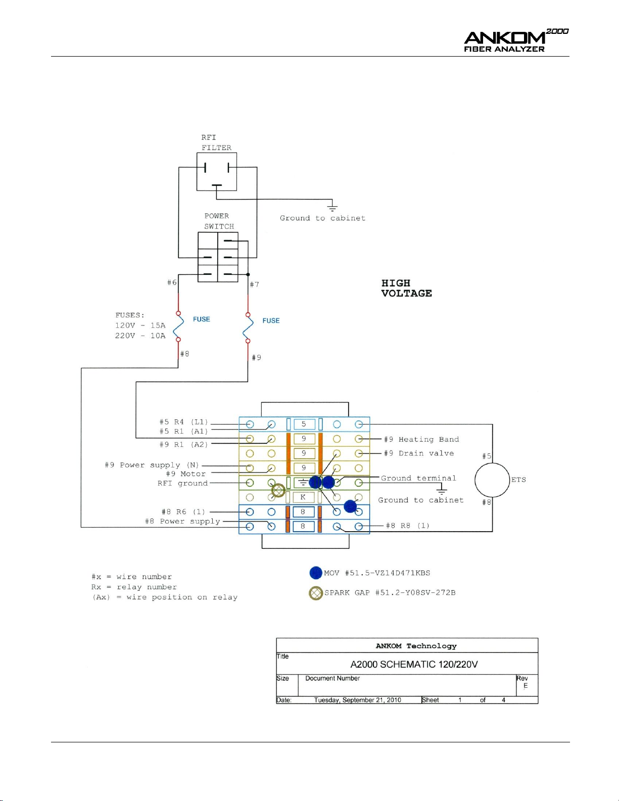
Operator’s Manual
Appendix E – Wiring Diagrams (1 of 4)
pg. 48 Rev E 1/14/15
Page 49

Operator’s Manual
Appendix E – Wiring Diagrams (2 of 4)
Rev E 1/14/15 pg. 49
Page 50

Operator’s Manual
Appendix E – Wiring Diagrams (3 of 4)
pg. 50 Rev E 1/14/15
Page 51

Operator’s Manual
Appendix E – Wiring Diagrams (4 of 4)
Rev E 1/14/15 pg. 51
Page 52
Automation saves time and money!
ANKOM Technology is an international company with products that include…
TDF Dietary Fiber Analyzer
Automates AOAC 991.43, 985.29, 2009.01, and 2011.25 (and associated AACC
methods)
IDF/SDF and TDF values
Faster, Technician-free Filtering
Computer controlled operation
Reduced per assay costs
A2000 Fiber Analyzer
Crude Fiber (AOCS Ba 6a-05), ADF, NDF
Automatically adds solutions and rinses
Batch process - up to 24 samples at one time
XT15 Fat Extractor
Official Method AOCS Am 5-04
Fully automatic
Solvent recovery at 97% or greater
Batch process - up to 15 samples at one time
RF Gas Production System
High sensitivity pressure measurement
Anaerobic activity analyses (rumen, yeast, beer/wine fermentation, biomass,
biodegradability, etc.)
Soil respiration
Wireless Computer control and data storage
Chemicals
A wide variety of chemicals used for many different lab operations
Pre-mixed solutions available
Please visit our web site at www.ankom.com for more information.
2052 O’Neil Rd, Macedon NY 14502
Telephone: (315) 986-8090
Fax: (315) 986-8091
www.ankom.com
 Loading...