

Page 1
ANGRY AUDIO
USER GUIDE
PHONE
+1 (615) 763 -3033
WEB
[email protected]
www.angr yaudio.com
ADDRESS
128 HOLIDAY CT S TE 118
Franklin TN 370 67 USA
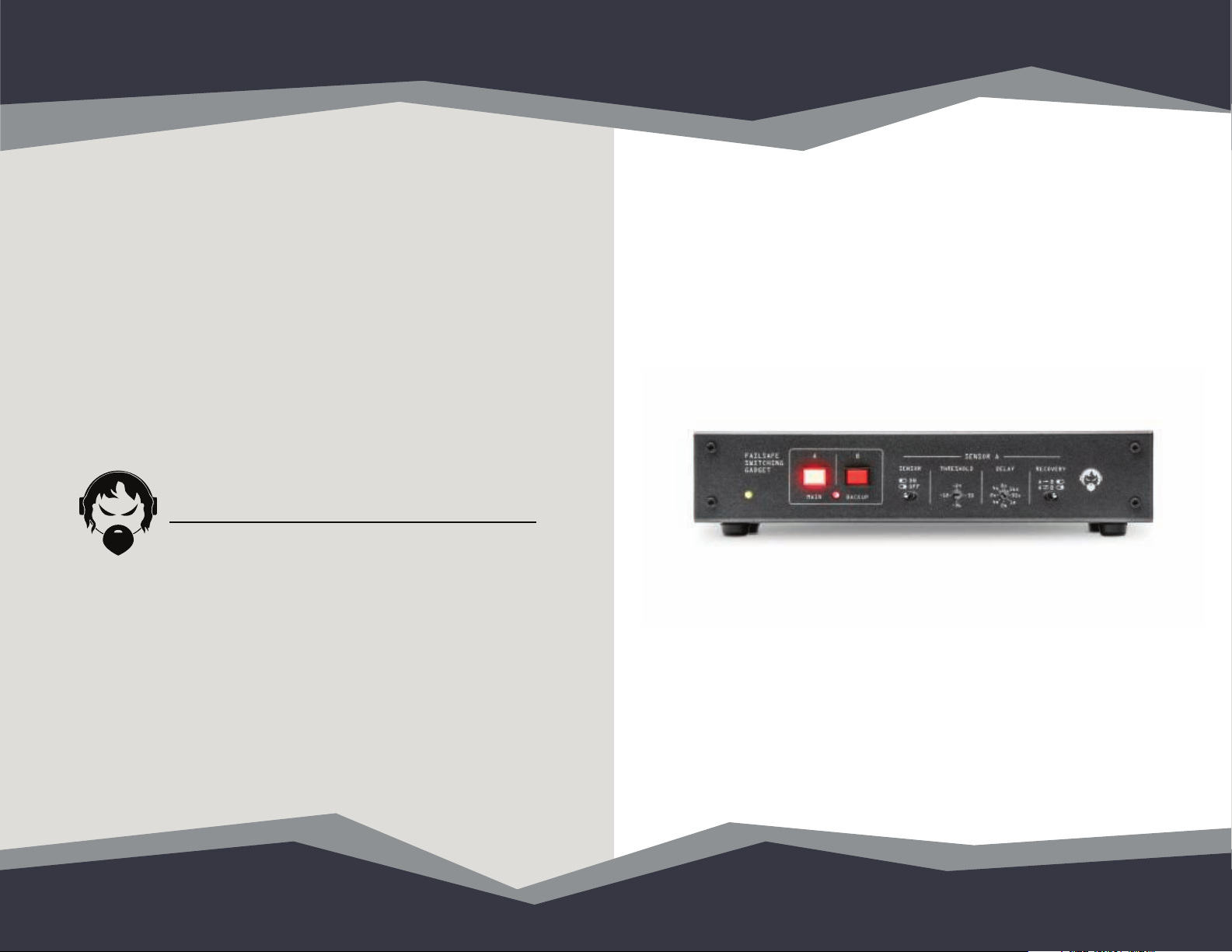
Failsafe Gadget
P/N 991009
Page 2
1 Welcome! Safety First 2
Welcome to the world of Angry Audio,
home of the audio gadgets.
The audio world is filled with complex, high-tech gear. Much of it bristles with
seductive shapes and eye-catching lights and displays, and all of it promises to
make things sound better and open up new creative possibilities.
But in order for those products to shine, you still have to get the basics right and
sweat the details. Good audio isn’t made by one component. It’s made by getting
things right every step of the way, especially the little things.
Accordingly, every audio gadget – including the Failsafe Gadget – is designed
to solve common yet critical problems, and are meticulously engineered with
performance and longevity in mind to deliver pristine audio for many years.
Our promise and guarantee.
We know you’ll love your Failsafe Gadget, but the universe is a strange place, so
it’s always possible that you won’t. That’s why we give you 30 days to bond with
your gadget. If the two of you can’t get your chakras to align, we’ll buy it back.
Plus, every gadget is warrantied to be free from defects in parts and workmanship
for two full years after you purchase it. If a gadget fails within this time period,
Angry Audio will, at its discretion, repair or replace it so long as you let us know
of the failure within the warranty period and can provide proof of purchase in the
form of a dated sales receipt. You can call us at +1 615-763-3033, or reach us
online at at www.angryaudio.com/contact.
Making a good rst impression.
When you unbox your Failsafe Gadget, we really hope it makes a good first
impression and that you take a moment to appreciate the lengths we’ve gone
to in order to create a “built for broadcast” product. All audio gadgets are overengineered to provide long-term reliability and guaranteed RFI immunity.
Some of this is apparent - such as the rugged powder-coated steel chassis - but
much of this goodness is invisible, like the premium components used in the
audio path. Even if you can’t see it, you’ll hear it!
A word or two about safety.
Most of this falls under the category of common sense, but the company
lawyers started to visibly twitch when we suggested we didn’t need to spell out
the obvious. Besides, extensive testing with volunteer focus groups resulted in
over 100% of the participants who got a user guide without safety instructions
immediately plugging in the device and jumping recklessly into their (filled)
bathtubs. After a few weeks of this, we grew concerned our customer base was
eroding, so safety warnings it is.
Audio gadgets aren’t meat slicers or TIG welders, but still, they are intended to be
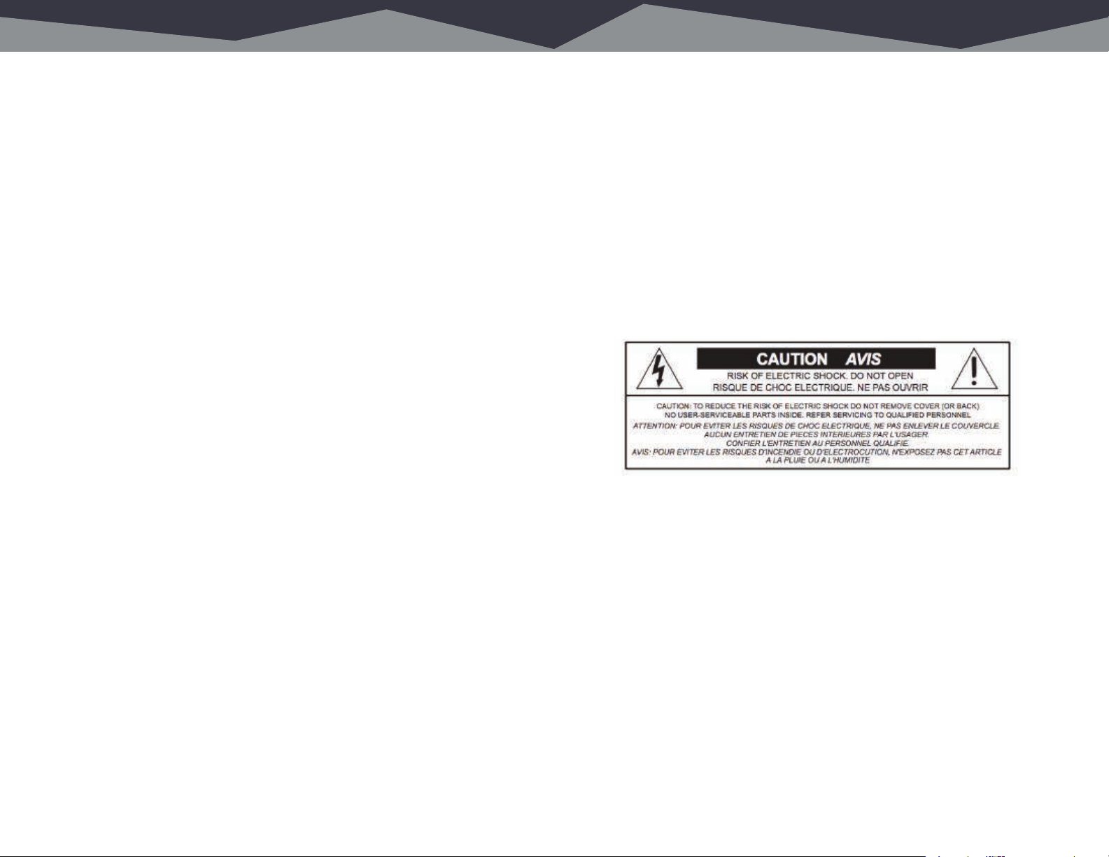
used by qualified personnel only. To avoid electric shock, do not open the unit or
attempt to perform any servicing unless you are qualified to do so.
The Failsafe Gadget has internal 120VAC or 240VAC power supply. Hazardous
voltages are present whenever the unit is plugged in and may still be present on
certain components even when the unit is unplugged.
The power cord is the primary disconnect device and so the outlet providing
power to the gadget should be easily accessible. In other words, make sure you
can back out of making any bad electrical decisions by yanking the plug. Use
only a properly grounded outlet for power. Do not cut the ground pin or use a
ground-lifting adapter, and do not defeat the polarized plug. Do not overload
outlets.
Do not expose your gadget to rain or moisture. Do not block any ventilation
openings, as lack of airflow could damage the unit or create a fire hazard.
Any electronic device can fail without warning; do not use this product in
applications where a life threatening condition could result due to failure.
Do not buy candy for trick-or-treat that you yourself will not eat. Do not start saying
things like, “When I was a kid…” – it’s a slippery slope to Curmudgeon Town. Do
not wear a black belt with blue polyester slacks – this is white-belt-only territory.
Page 3
3 Rack Mounng Wall Mounng 4
Mounting your Failsafe Gadget in a rack.
The Failsafe Gadget sits on four rubber feet that ensure it won’t scratch the zebra
wood inlays on your antique mahogany desk.
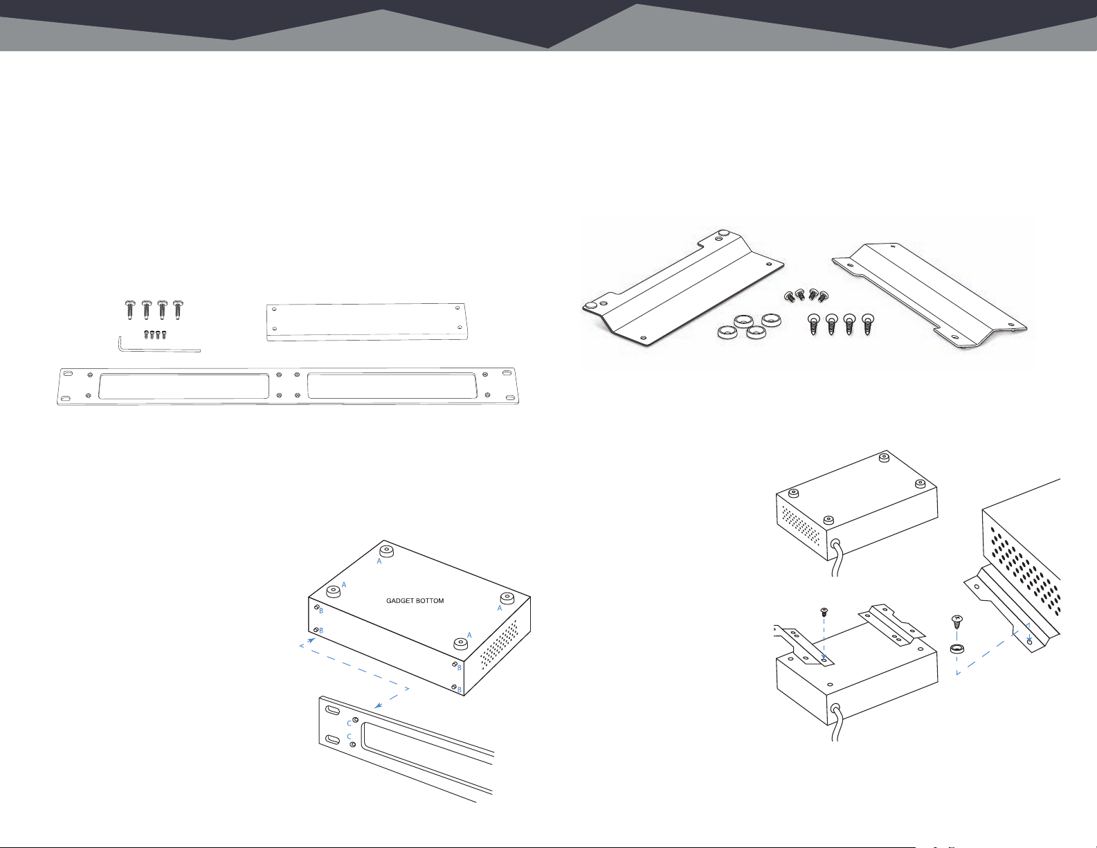
If you prefer to rack mount your gadgets, you’ll need the optional Rack Mount kit
which allows one or two gadgets to be installed side by side in a standard 1RU
rack space.
Each Rack Mount Kit consists of a custom rack panel with cut outs for all front
panel controls and displays. A blank filler panel is also provided if you are
mounting only one gadget.
When rack mounting, remove the four rubber feet (“A”) from the bottom of the
gadget with a #1 Phillips screwdriver.
Remove the four front panel 3/32” hex screws (“B”). You can rummage around
your toolbox for your own hex key, or use the one we thoughtfully provide in the
mounting kit.
Line up the gadget so that the holes
exposed after removing the socket
head screws line up with the mounting
holes (“C”) in the rack panel.
Attach the rack panel to the front of
your gadget with the same screws you
just removed. If you dropped one and
it immediately rolled to an inaccessible
location (as these things always do),
don’t panic – we’ve included spares in
the kit.
Attaching your Failsafe Gadget to a wall.
If you prefer to secure your gadget to the inside of a rack, cabinet, or other flat
surface, the optional Wall Mount kit comes in handy.
Each Wall Mount Kit includes two brackets, four No. 6 screws, and four cup
washers.
Remove the four rubber feet (“A”) from the bottom of the gadget with a #1 Phillips
screwdriver, being careful to save the screws.
Align the bracket holes with
the holes in the bottom of the
gadget, then attach the brackets
using the screws removed from
the rubber feet.
Use the four No. 6 screws
(“B”) and the four cup washers
(“C”) to secure the gadget to a
plywood surface. Drilling pilot
holes is recommended to reduce
the risk of splitting the wood.
Different hardware (not supplied)
will be required if you are
mounting the gadget to a drywall
(or other) surface.
A
A
A
A
A
B
C
Finally, use the provided rack screws
(all four, please) to mount your gadgets.
Page 4
5 Under Counter Mounng Desktop Mounng 6
Mounting your Failsafe Gadget under a counter.
Your Failsafe Gadget can be mounted under a counter, desk, or table using the
optional Under Counter Mount Kit.
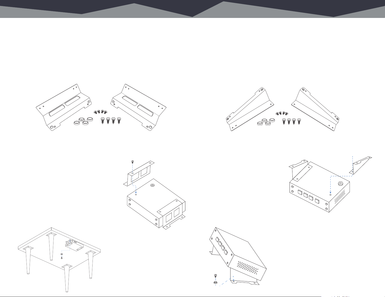
This kit includes two brackets, four No. 6 wood screws, and four cup washers
suitable for mounting to a plywood surface. Different hardware (not supplied) may
be needed if the mounting surface is a different material.
Remove the four rubber feet (”A”) from the bottom of the gadget using a #1
Phillips screwdriver, being careful to save the screws.
Line up the brackets (“C”) so that their
mounting holes line up with holes exposed
after removing the rubber feet. Orient the
brackets as shown in the diagram to the right
so that the deeper flat side supports the gadget
and the “notched” side faces the
under-mount surface.
Use the panhead screws (“B”) removed from
the rubber feet to secure the brackets to the
gadget.
Use the four provided No. 6 screws
(“D”) and the four cup washers (“E”)
as shown in the diagram to the left
E
D
to secure the gadget to the plywood
underside of the counter, desk, or
table.
Drilling pilot holes is recommended
to reduce the risk of splitting the
wood.
B
C
A
GADGE T BOTTOM
C
Using your Failsafe Gadget on a desktop.
If you like the idea of using the Failsafe Gadget on a desktop but prefer a more
permanent installation along with the convenience of having it angled up toward
the user, we’ve got you covered with the optional Desktop Bracket Kit.
This kit includes two brackets, four No. 6 wood screws, and four cup washers
suitable for mounting to a plywood surface. Different hardware (not supplied) may
be needed if the mounting surface is a different material.
Remove the four rubber feet (“A”) from the bottom of the gadget using a #1
Phillips screwdriver, being careful to save the screws.
With the bottom of the gadget facing
up and the front panel facing toward
you, line up bracket “C” with the holes
D
exposed after removing the feet on
the right side of the gadget. Orient the
bracket as shown in the diagram to the
right so that the flat side is attached to
the gadget, and the “notched” side sticks
up with the notch facing outwards. Use
the panhead screws (“B”) removed from
the rubber feet to secure the brackets to the gadget.
Use the four provided No. 6 screws (“E”)
and cup washers (“F”) as shown in the
diagram above to secure the gadget to a
plywood surface.
Drilling pilot holes is recommended to
reduce the risk of splitting the wood.
E
F
GADGET BOTTOM
A
C
Page 5
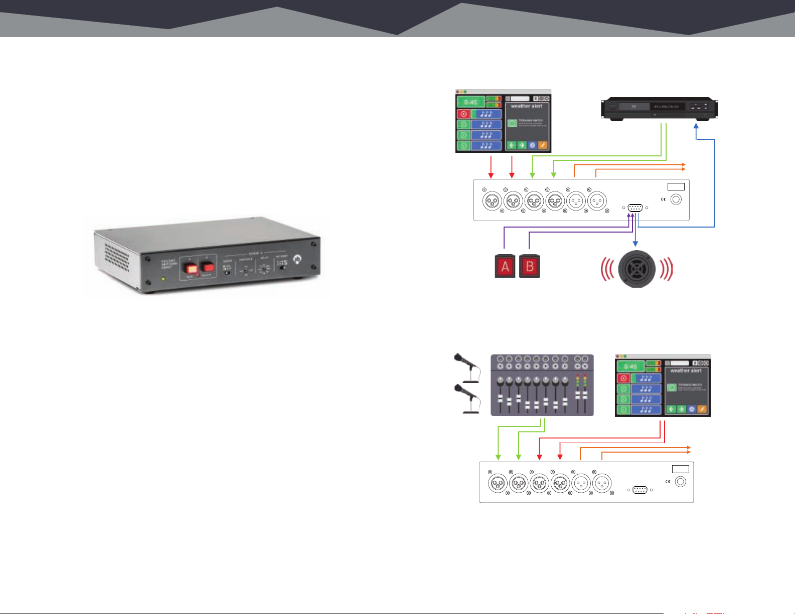
7 The Failsafe Gadget Explained A Typical Applicaon 8
The most dreaded words in radio...
There are a host of things that can induce panic at a radio station. A dip in the
ratings. The espresso machine in the break room taking a dirt nap. Someone from
sales driving the engineering van. A promotions event involving a helicopter and
turkeys. But none quite as chilling as the words “Dead Air.”
Dead air can result from malfunctioning equipment to air talent getting locked out
of the building after a botched attempt at a convenience store run. Regardless,
dead air almost always occurs in the dead of night, and we thought it would be
nice to have a way to deal with these off-air emergencies without being dragged
out of a warm bed. Enter the Failsafe Gadget.
t
At its core, the Failsafe Gadget is a stereo A/B switch - but with an important twist.
When it detects silence on its primary input, it automagically feeds its output with
audio from a secondary input such as a looping CD player, a portable music
player, or a backup automation computer. You decide what threshold constitutes
silence, how long the gadget waits before switching sources, and whether or not
it switches back to the primary source by itself when audio is restored. It can even
start the backup audio source or trigger an alarm when silence is detected.
Failsafe Gadget set up to replace missing audio.
Primary Audio Source
DESIGNED IN NASHVILLE, MANUFACTURED IN CHINA.
REMOTE SWITCH
INPUT B RLINPUT A RL
OUTPUT RL
Secondary Audio Source
To STL
ANGRYAUDIO.COM
LOGIC
PN 991009
SN 00001
Failsafe Gadget set up to insert external audio.
Secondary Audio Source
Primary Audio Source
In the event of a power failure, a relay bypass circuit routes the backup audio to
the output (as a loss of power to the Failsafe Gadget likely means a loss of power
to the main audio source). Be sure your backup source is fed from a UPS or a
different circuit to take advantage of this feature.
Alternatively, you get set up the Failsafe Gadget so that the presence of a signal
(rather than the absence of one) sets things into motion by feeding the primary
audio into the B input and routing the override audio into the A input. When audio
appears on the (normally quiet) A side, it interrupts the B side audio. When the A
side goes quiet, the B side once again feeds the output. This can be useful for
inserting emergency audio or for interrupting regular programming from a remote
event during unattended operation.
Of course, you can bypass the sensor and manually switch between two audio
sources for programs that only need automatic switching during unattended
segments with either the front panel buttons or remotely using the logic port.
INPUT B RLINPUT A RL
DESIGNED IN NASHVILLE, MANUFACTURED IN CHINA.
To STL
OUTPUT RL
ANGRYAUDIO.COM
LOGIC
PN 991009
SN 00001
Page 6
9 Front & Rear Panel Details Logic Circuit 10
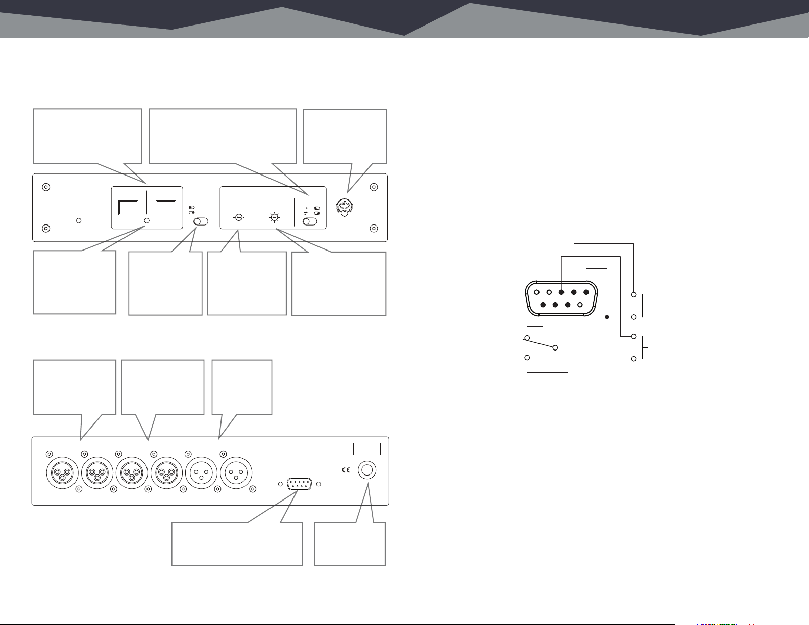
Buttons, knobs, switches, lights, and connections.
Or, ”What happens if I push this button?”:
Illuminated buttons
indicate which source is
currently on-air and allow
manual switching of audio
source.
FAILSAFE
SWITCHING
GADGET
MAIN BACKUP
Silence indicator.
Green = above
threshold (audio).
Red = below
threshold (silence).
And a look at the back panel:
Primary audio input
on balanced,
+4dBu female XLR
input jacks.
ENGINEERED & ASSEMBLED IN NASHVILLE, USA.
Recovery switch determines if primary
audio will be automatically routed
back to air when it returns, or if the
gadget will keep the backup source
on-air until it is manually switched.
A B
MANUAL
SENSOR
-18
Sensor bypass
toggles between
manual and
automatic
source
switching.
Secondary audio
input on balanced,
+4dBu female XLR
input jacks.
INPUT B RLINPUT A RL
Threshold control
determines what
level constitutes
silence, triggering
the switch to the
backup source.
Output on
balanced,
+4dBu male
XLR jacks.
OUTPUT RL
-24
-36
-30
SENSOR
DELAY RECOVERYTHRESHOLD
8s
4s
2s
4m
2m
Angry Audio guy.
Just look at how
much he despises
dead air.
A B
16s
A B
30s
1m
Delay control
determines how long
the gadget waits after
audio falls below the
threshold to switch to
the backup source.
ANGRYAUDIO.COM
LOGIC
PN 991009
SN 00001
Connecting to the outside world.
The 9-pin DSUB connector on the rear panel of the Failsafe Gadget serves as
a handy logic port for manually switching between the A and B audio sources
remotely, and for starting the the backup audio source or triggering a silence
alert.
The pin-outs are as follows:
1: Common 6: Relay B
2: Remote A (Main Source) 7: Relay C
3: Remote B (Backup Source) 8: Relay A
4: No connection 9: Common
5: No connection
123
A (MAIN)
876
B (NC)
A (NO)
C
A momentary contact closure to ground via a pushbutton can remotely switch
between the A and B sources, which exactly mimics the front panel buttons. To
select A, short Pin 2 to Pin 1. To select B, short Pin 3 to Pin 1. An open collector to
ground or relay contact to ground will also activate these inputs.
Dry relay contacts provide A/B switch status. If source A is active, Pin 8 will be
shorted to Pin 7. If source B is active, Pin 6 will be shorted to Pin 7. Please note
this relay is intended to switch small logic signals; never connect the logic port to
AC mains power.
B (BACKUP)
Logic port for remote manual
switching between sources and
for starting the backup source
and/or triggering a silence alert.
120V or 240V
AC power cord.
If soldering or crimping pins for a DSUB connector makes you nervous or sad,
we’ve included a DB9M to RJ45F adapter in the box for the convenience of wiring
with CAT5/6 cable. Happy now?
Page 7
11 Block Diagrams Specicaons 12
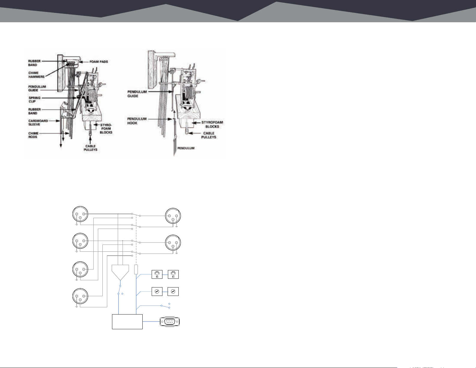
A closer look at the pendulum and chimes.
Whoops - we totally thought you said CLOCK
diagram. Let’s try again.
MAIN (A)
INPUT L
MAIN (A)
INPUT R
ALT (B)
INPUT L
ALT (B)
INPUT R
1 2
3
1 2
3
1 2
3
1 2
3
SENSOR
ON
231
231
A B
DELAY LEVEL
A > B
A > B > A
LEFT
OUTPUT
RIGHT
OUTPUT
Riveting data about your gadget.
Part Numbers
Failsafe Gadget (115VAC, US plug) Part No. 991009
Failsafe Gadget (230VAC, Europe plug) Part No. 991009E
Failsafe Gadget (230VAC, Australia plug) Part No. 991009A
Failsafe Gadget (230VAC, UK plug) Part No. 991009U
A/B Pushbutton Switches
Momentary action, LED illuminated
Connections
Inputs A & B Female +4dBu balanced XLR
Output Male +4dBu balanced XLR
Logic Port Female DB-9 Sub
Power and Environmental
North American Config. 115VAC 60Hz, NEMA 5-15P power plug
Export Versions 230VAC 50/60Hz, various plugs
Power Consumption 4VAC
Operating Temperature 0º to 40º C (32º to 104º F)
Storage Temperature -20º to 45º C (-4º to 113º F)
Relative Humidity 0% to 90% non-condensing
Cooling Vented chassis (fanless)
Product Weight & Dimensions
Width x depth x height 8.5 x 6.25 x 1.70 in., 21.6 x 16 x 4.32 cm.
Weight 3.5 pounds, 1.6 kilograms
Shipping Weight & Dimensions
Length x width x height 12 x 9 x 6 in., 31 x 23 x 16 cm.
Weight 5 pounds, 2.3 kilograms
Box includes:
Failsafe Gadget
2x Dual XLRM to RJ45F (StudioHub) adapters
1x Dual XLRF to RJ45F (StudioHub) adapters
DB9F to RJ45F adapter for logic port
LOGIC
FAILSAFE GADGET FUNCTIONAL BLOCK DIAGRAM
LOGIC
PORT
Page 8

13 Compliance Blank Page 14
In The U.S.
In the U.S., this gadget complies with the limits for a Class A computer device
as specified by FCC Rules, Part 15, Subpart J, which are designed to provide
reasonable protection against such interference when this type of equipment is
operated in a commercial environment.
In Canada
In Canada, this gadget does not exceed the Class A limits for radio noise
emissions set out in the Radio Interference Regulations of the Canadian
Department of Communications.
In Europe
This gadget complies with the requirements of the EEC Council Directives
93/68/EEC (CE Marking), 73/23/EEC (safety – low voltage directive), and
89/336/EEC (electromagnetic compatibility). Conformity is declared to standards
EN50081-1 and EN50082-1
Well, that was poor planning.
So how about about some tic-tac-toe?
Or a word search?
Y K V M Q D R A T W
E D Q U O E G S W K
A N G R Y A U D I O
J Q Q P Y D N A H G
P N C H O A A Q A U
P V V Y R I X D F D
V K H S P R G O D O
I U I L J E A V H N
P B V A T N H G S R
A B S W I T C H S W
ABSWITCH ANGRYAUDIO DEADAIR GADGET HANDY MURPHYSLAW
Draw a pretty picture!
Page 9
15 Schemacs Schemacs 16
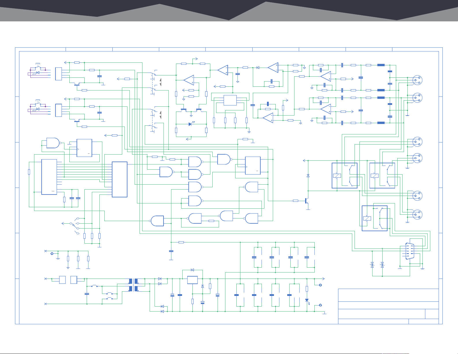
Where the electrons go inside the Failsafe Gadget.
1 2 3 4 5 6 7 8 9
A
B
C
D
E
F
A(MAIN)
EXT_SW1
B(BACKUP)
EXT_SW2
11
R1
1M0
12
ACLINEGND
#4_PLATED_HOLE
ACLINEHOT
ACLINENTL
TS-LED
TS-LED
IC1
4060D
12
13
I
R
PAD1
PAD2
PAD3
P1-4
P1-3
P1-2
P1-1
P2-4
P2-3
P2-2
P2-1
IC4D
4093D
Q4
Q5
Q6
Q7
Q8
Q9
Q10
Q12
Q13
Q14
P0
P0
MH1
+5.50V
X1
4
4
3
3
2
2
1
1
B4B-XH-A
MMBT2222
+5.50V
X2
4
4
3
3
2
2
1
1
B4B-XH-A
MMBT2222
11
DGND
7
5
4
6
14
13
15
1
2
3
9
10
R2
261K
DELAY
C*2
+5.50V
CGND
R3
AGND
FS1
1
1
2
2
120:J1Y,J2N,J3Y,F1=0.5A
240:J1N,J2Y,J3N,F1=0.25A
R4
10K0
R11
220R
100nF
C2
T1
R8
10K0
R5
10K0
T2
R9
10K0
IC9B
8
S
9
D
11
CLK
10
R
4013D
100N
100N
C36
C1
1
S1
2
DGND
R12
220R
100nF
C3
DGND
0V
+5.5
13
Q
12
Q
13
14
15
12
11
10
R15
+5.50V
100K
R64
100K
IC3
1
5
2
4
6
9
4051D
3
X0
X
X1
X2
X3
X4
X5
X6
X7
INH
A
B
C
4
8
R7
R14
R13
100K
100K
100K
DGND
R6
0Ω
0Ω
0Ω
R10
PGND
DGND
FS2
1
1
2
2
C20
0.01UF
J1
1 2
1 2
1 2
J2
J3
TR1
1
2
3
P2 P1
4 8
FS16-400-C2
3
2
1
S3A
MANUAL
6
SENSOR
5
4
S3B
3
2
1
S4A
RETURNB-A
STAYONB
6
5
4
S4B
R18
100K
DGND
5
IC8B
6
4093D
IC2D
11
4093D
D1
FM4007W
5
S2S1
6
7
D2
FM4007W
FM4007W
FM4007W
1000UF35V
D3
D4
LM393D
+5.50V
R16
10K0
MMBT2222 MMBT2222
T3 T4
R17
220R
R20
100K
4
12
13
R29
1M0
470NF
C25
DGND
+
C4
R19 R24
1K0 1K0
IC7B
6
7
5
R21
10K0
R22
10K0
AGND
AGND
GRNRED
LED2
SSF-LXH103HGW
+5.50V
5
IC2B
6
4093D
8
IC4C
9
4093D
8
IC8C
9
4093D
8
IC2C
9
4093D
IC4A
3
4093D
D5
FM4007W
IC5
LM317MDCYR
IN OUT
ADJ
100N
C5
R23
750R
+5.50V
1
2
+
R25
R26
4
10
10
10
FM4007W
C6
47U10V
D6
10K0
220R
R27
1M0
R28
47U10V
+5.50V
R33
220R
IC7A
2
LM393D
1
3
R32
49K9
1
8
1
C1
C2
C1
4
2
4
S2
R31
R37
274R
1K10
1
IC2A
3
2
4093D
12
IC8D
11
13
4093D
100nF 100nF100nF
C7
+
C8 C17C15
R36
49K9
C9
4U70
AGND
THRESHOLD
8
C2
2
R35
2K21
AGND
R65
100K
IC9A
6
S
5
D
3
CLK
4
R
4013D
3
4
100nF 100nF 100nF 100nF
147
VDDVSS
100nF
IC8P
8
D7
C16
10P0
R39
10K0
100P
C13
C10
4U70
R38
10K0
13
14
12
IC10D
536R
LMH6644
DGND
1
Q
2
Q
1
IC8A
2
4093D
5
IC4B
6
4093D
147
VDDVSS
IC2P
C11 C14 C18 C19
VDDVSS
IC1P
C12
8 16
IC10C
LMH6644
FM4007
49K9
DGND
AGND
LMH6644
AGND
D9
FM4007W
T5
MMBT2222
IC10IC7
C21
IC10A
LMH6644
49K9
C22
IC10B
411
R48
100P
1
C23
R50
R49
100P
7
C24
R51
C28
47N0
2
R53
3
100K
100P
C26
47N0
100K
C29
47N0
6
R54
5
100K
100P
C27
47N0
100K
K1
3
TQ2-5V
8
10 1
R42
10
4k99
9
R47
AGND
10K0
R44
10K0
+5.50V
R40
VDDVSS
IC9P
R45
10K0
10K0
R41
10K0
AGND
+5.50V
R43
10K0
84
7 14
+5.50V
TP1
147
VDDVSS
IC4P
R46
220R
IC3P
LED3
VEE
GND VCC
7
8 16
SSF-LXH103LGD
TP2
DGND
TITLE:
DocumentNumber:
Date: Sheet:
R60
+5.50V
+5.50V
R56
20K0
C30
2N20
R57
20K0
R58
20K0
C31
2N20
R59
20K0
24
K1
K1
97
20K0
R61
20K0
R62
20K0
R63
20K0
10 1
K2
TQ2-5V
DZ2
L1
100PF
100PF
L2
L3
100PF
100PF
L4
K3
TQ2-5V
10 1
24
K2
3
8
K2
97
DZ3
P4SMA6.8CA
C32
C33
C34
C35
24
K3
3
8
K3
97
P4SMA6.8CA
DGND
X4
1
3
2
G
NC3FAH2-0
X5
1
3
2
G
NC3FAH2-0
CGND
X6
1
3
2
G
NC3FAH2-0
X7
1
3
2
G
NC3FAH2-0
CGNDCGND
G
X8
2
3
1
NC3MBH
G
X9
2
3
1
NC3MBH
SH1SH2
1
6
2
7
3
8
4
9
5
X3
CGND
ANGRYAUDIOLLC
FailsafeGadget
991009 D2
7/29/228:25AM 1/1
AINL
AINR
BINL
BINR
OUTL
OUTR
REV:
A
B
C
D
E
F
 Loading...