

Page 1

ANGRY AUDIO
USER GUIDE
PHONE
+1 (615) 763 -3033
WEB
[email protected]
www.angr yaudio.com
Rev. 1.3 - August, 2020
ADDRESS
128 HOLIDAY CT S TE 118
Franklin TN 370 67 USA
Balancing Gadgets
P/N 991001 Stereo Balancing Gadget
P/N 991002 Dual Stereo Balancing Gadget
P/N 991003 Bidirectional Balancing Gadget
Page 2

1 Welcome! Safety First 2
Welcome to the world of Angry Audio,
home of the audio gadgets.
The audio world is filled with complex, high-tech gear. Much of it bristles with
seductive shapes and eye-catching lights and displays, and all of it promises to
make things sound better and open up new creative possibilities.
But in order for those products to shine, you still have to get the basics right and
sweat the details. Good audio isn’t made by one component. It’s made by getting
things right every step of the way, especially the little things.
Accordingly, every audio gadget – including the Balancing Gadgets – are
designed to solve common yet critical problems, and are meticulously engineered
with performance and longevity in mind to deliver pristine audio for many years.
Our promise and guarantee.
We know you’ll love your Balancing Gadget, but the universe is a strange place,
so it’s always possible that you won’t. That’s why we give you 30 days to bond
with your gadget. If the two of you can’t get your chakras to align, we’ll buy it
back.
Plus, every gadget is warrantied to be free from defects in parts and workmanship
for two full years after you purchase it. If a gadget fails within this time period,
Angry Audio will, at is discretion, repair or replace it so long as you let us know
of the failure within the warranty period and can provide proof of purchase in the
form of a dated sales receipt. You can call us at +1 615-763-3033, or reach us
online at at www.angryaudio.com/contact.
A word or two about safety.
Most of this falls under the category of common sense, but the company lawyers
started to visibly twitch when we suggested we didn’t need to go beyond a simple
“Don’t use your gadget in the bathtub” warning. Besides, our market research
indicates that injured (or dead) customers can’t be relied upon to buy more stuff,
which we’re told is a critical element to a successful business. Who knew?
Audio gadgets aren’t chainsaws or flamethrowers, but still, they are intended to be
used by qualified personnel only. To avoid electric shock, do not open the unit or
attempt to perform any servicing unless you are qualified to do so.
Balancing Gadgets have internal 120VAC or 240VAC power supplies. Hazardous
voltages are present whenever the unit is plugged in and may still be present on
certain components even when the unit is unplugged.
The power cord is the primary disconnect device and so the outlet providing
power to the gadget should be easily accessible. In other words, make sure you
can back out of making bad electrical decisions by yanking the plug. Use only a
properly grounded outlet for power. Do not cut the ground pin or use a groundlifting adapter, and do not defeat the polarized plug. Do not overload outlets.
Making a good rst impression.
When you unbox your Balancing Gadget, we really hope it makes a good first
impression and you take a moment to appreciate the lengths we’ve gone to
in order to create a “built for broadcast” product. All audio gadgets are overengineered to provide long-term reliability and guaranteed RFI immunity.
Some of this is apparent - such as the rugged powder-coated steel chassis - but
much of this goodness is invisible, like the low-noise, internal linear power supply
or the direct coupled transformer-less analog circuitry. Even if you can’t see it,
you’ll know its there by the absence of hum, buzz, hiss, or RFI.
Do not expose your gadget to rain or moisture. Do not block any ventilation
openings, as lack of airflow could damage the unit or create a fire hazard.
Do not run with scissors.
Page 3

3 Rack Mounng Wall Mounng 4
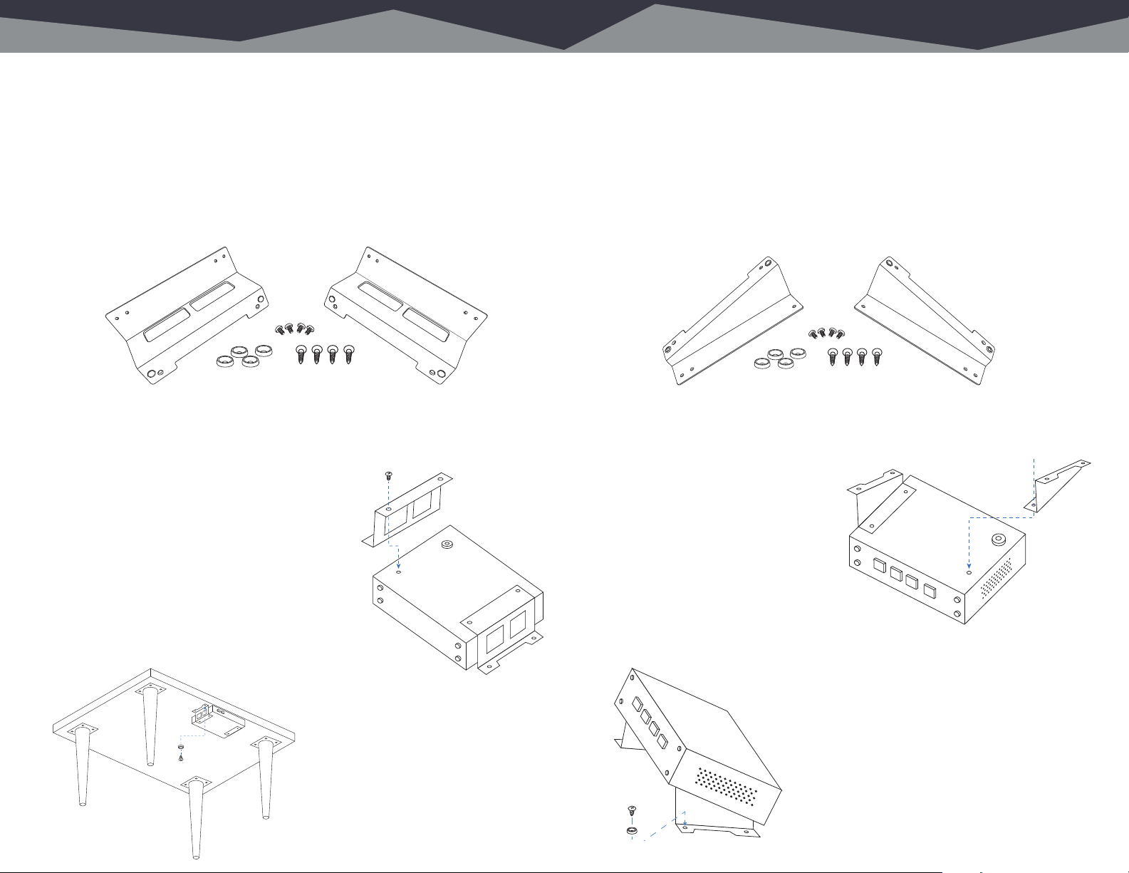
Remove 4 rubber feet (A) from bottom of gadget using #1 phillips screwdriver.
Retain the screws. Align the holes in the wall brackets with the holes in the
gadget bottom. Attach the brackets using the screws removed from the rubber
feet. Use four No.6 screws (B) and four cup washers (C) as shown to secure
gadget to a plywood surface. Different hardware (not supplied) will be needed
if the mounting surface is drywall.
Remove 4 rubber feet (A) from bottom of gadget using #1 phillips screwdriver.
Remove 4 socket head screws (B) from front of gadget using 3/32IN hex key.
Line up gadget so that the holes exposed after removing socket head screws
line up with the mounting holes (C) in the rack panel. Use 4 socket head
screws (B) to secure the gadget to the rack panel.
Rack mounting your Balancing Gadget
The Balancing Gadget sits on four rubber feet that ensure it won’t scratch the
zebra wood inlays on your antique mahogany desk.
If you prefer to rack mount your gadgets, you’ll need the optional Rack Mount kit
which allows one or two gadgets to be installed side by side in a standard 1RU
rack space.
Each Rack Mount Kit consists of a custom rack panel with cut outs for all front
panel controls and displays. A blank filler panel is also provided if you are
mounting only one gadget.
When rack mounting, remove the four rubber feet (“A”) from the bottom of the
gadget with a #1 Phillips screwdriver.
Remove the four front panel 3/32” hex screws (“B”). You can rummage around
your toolbox for your own hex key, or use the one we thoughtfully provide in the
mounting kit.
Line up the gadget so that the holes
exposed after removing the socket
head screws line up with the mounting
holes (“C”) in the rack panel.
Attach the rack panel to the front of
your gadget with the same screws you
just removed. If you dropped one and
it immediately rolled to an inaccessible
location
(as these things always do), don’t panic
– we’ve included spares in the kit.
Wall mounting your Balancing Gadget
If you prefer to secure your gadget to the inside of a rack, cabinet, or other flat
surface, the optional Wall Mount kit comes in handy.
Each Wall Mount Kit includes two brackets, four No. 6 screws, and four cup
washers.
Remove the four rubber feet (“A”) from the bottom of the gadget with a #1 Phillips
screwdriver, being careful to save the screws.
Align the holes in the wall
brackets with the holes in
the bottom of the gadget,
then attach the brackets
using the screws removed
from the rubber feet.
Use the four No. 6 screws
(“B”) and the four cup
washers (“C”) to secure
the gadget to a plywood
surface.
Different hardware (not
supplied) will be required
if you are mounting the
gadget to a drywall (or
other) surface.
A
A
A
A
A
B
C
Finally, use the provided rack screws
(all four, please) to mount your gadgets.
Page 4
Desktop Mounng 65 Under Counter Mounng
Remove 4 rubber feet (A) from bottom of gadget using #1 phillips screwdriver.
Line up brackets (C) so their mounting holes line up with the holes
exposed after removing feet. Orient the brackets as shown in the drawing.
Use 4 panhead screws (B) to secure the brackets to the gadget.
Use four No.6 screws (D) and four cup washers (E) as shown to secure gadget to a plywood surface.
Dierent hardware (not supplied) will be needed if the mounting surface is of a dierent material.
B
C
C
A
B
GADGET BOTTOM
A
B
C
D
Remove 4 rubber feet (A) from bottom of gadget using #1 phillips screwdriver.
Line up brackets (C) so their mounting holes line up with the holes
exposed after removing feet. Orient the brackets as shown in the drawing.
Use 4 panhead screws (B) to secure the brackets to the gadget.
Mounting your Balancing Gadget under a counter.
Your Balancing Gadget can be mounted under a counter, desk, or table using the
optional Under Counter Mount Kit.
This kit includes two brackets, four No. 6 wood screws, and four cup washers
suitable for mounting to a plywood surface. Different hardware (not supplied) may
be needed if the mounting surface is a different material.
Remove the four rubber feet (”A”) from the bottom of the gadget using a #1
Phillips screwdriver, being careful to save the screws.
Line up the brackets (“C”) so that their
mounting holes line up with holes exposed
after removing the rubber feet. Orient the
brackets as shown in the diagram to the right
so that the deeper flat side supports the gadget
and the “notched” side faces the
under-mount surface.
Use the panhead screws (“B”) removed from
the rubber feet to secure the brackets to the
gadget.
E
D
Use the four provided No. 6 screws
(“D”) and the four cup washers (“E”)
as shown in the diagram to the left
to secure the gadget to the plywood
underside of the counter, desk, or
table.
Drilling pilot holes is recommended
to reduce the risk of splitting the
wood.
B
C
A
GADGE T BOTTOM
Using your Balancing Gadget on a desktop.
If you like the idea of using the Balancing Gadget on a desktop but prefer a more
permanent installation along with the convenience of having it angled up toward
the user, we’ve got you covered with the optional Desktop Bracket Kit.
This kit includes two brackets, four No. 6 wood screws, and four cup washers
suitable for mounting to a plywood surface. Different hardware (not supplied) may
be needed if the mounting surface is a different material.
Remove the four rubber feet (“A”) from the bottom of the gadget using a #1
Phillips screwdriver, being careful to save the screws.
With the bottom of the gadget facing
up and the front panel facing toward
you, line up bracket “C” with the holes
exposed after removing the feet on
the right side of the gadget. Orient the
D
GADGET BOTTOM
A
bracket as shown in the diagram to the
right so that the flat side is attached to
the gadget, and the “notched” side sticks
up with the notch facing outwards. Use
the panhead screws (“B”) removed from
the rubber feet to secure the brackets to the gadget.
C
Use the four provided No. 6 screws (“E”)
and cup washers (“F”) as shown in the
diagram above to secure the gadget to a
plywood surface.
Drilling pilot holes is recommended to
reduce the risk of splitting the wood.
E
F
C
Page 5
7 Types of Balancing Gadgets Stereo Balancing Gadget 8
IHF INPUT
PRO OUTPUT
R
L
RL
STEREO
BALANCING
GADGET
L R
IHF INPUT
PN 991001
SN 00001
120 VAC
ANGRYAUDIO.COM
The same, but different.
We manufacture three types of Balancing Gadgets: A stereo version, a dual stereo
version, and a bi-directional version. All feature low-distortion, low-noise analog
circuitry, our exclusive input stage to reduce ground loop noise, and include DC
offset correction. The output amplifiers are capable of driving a +26dBu signal
into long cable runs, even into low impedance 600Ω loads (+24dBm).
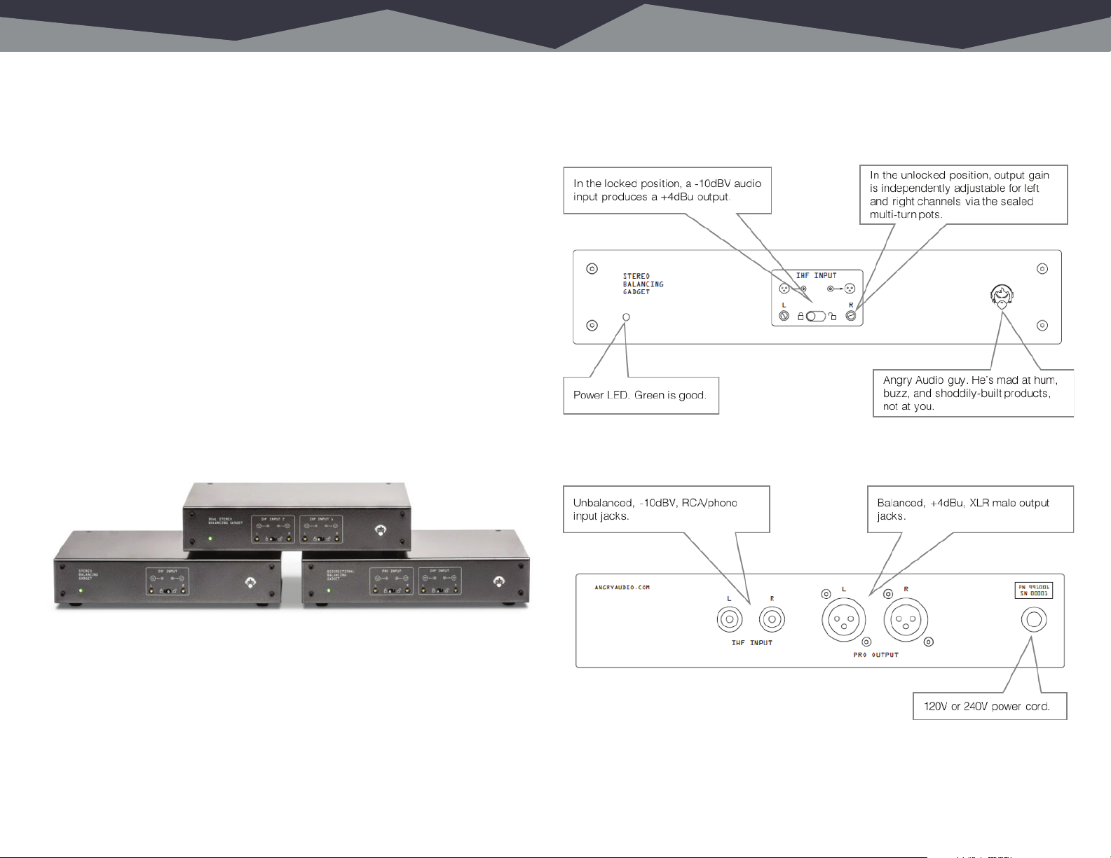
The Stereo Balancing Gadget converts unbalanced stereo -10dBV audio via
two RCA/phono jacks to professional +4dBu fully balanced outputs on two XLR
connectors, making it possible to feed professional gear with consumer audio
devices.
The Dual Stereo Balancing Gadget is identical to the Stereo Balancing Gadget,
but – as you may have already guessed – it offers two independent stereo
unbalanced inputs to two stereo balanced outputs.
The Bidirectional Balancing Gadget converts one stereo pair from unbalanced
to balanced, and another pair from balanced back to unbalanced. This makes it
ideal for situations where the source and destination signals come from and go to
unbalanced consumer devices, but must interface with a piece of pro audio gear
in the process.
A peak at the front panel.
This isn’t exactly rocket surgery, but let’s take a look at the front panel of the
Stereo Balancing Gadget.
Meanwhile, around back...
ENGINEERED & ASSEMBLED IN NASHVILLE, USA
Page 6

9 Dual Stereo Balancing Gadget Bidireconal Balancing Gadget 10
IHF INPUT
PRO OUTPUT
R
L
RL
STEREO
BALANCING
GADGET
L R
IHF INPUT
PN 991001
SN 00001
120 VAC
ANGRYAUDIO.COM
IHF INPUT
PRO OUTPUT
R
L
RL
STEREO
BALANCING
GADGET
L R
IHF INPUT
PN 991001
SN 00001
120 VAC
ANGRYAUDIO.COM
Front Panel.
Almost identical to the Stereo Balancing Gadget, but with two inputs and outputs.
Rear Panel.
Front Panel.
The Bidirectional Balancing Gadget is somewhat different in that it converts one
stereo unbalanced pair from unbalanced to balanced, and another pair from
balanced back to unbalanced.
Rear Panel.
ENGINEERED & ASSEMBLED IN NASHVILLE, USA
ENGINEERED & ASSEMBLED IN NASHVILLE, USA
Page 7

11 Unbalanced Connecons Balanced Connecons 12
Understanding unbalanced audio.
An unbalanced connection or cable is made up of two conductors (wires). One
wire carries the audio signal, while the other serves as the shield. The most
common example of this is the RCA or phono cable, where the center conductor
carries the signal and the outer ring is the shield and signal
return.
Unbalanced audio is most often encountered in consumer
electronics equipment. It is suitable for very short
interconnections, especially when the source and destination
are plugged into the same power source. Unfortunately, when
used to connect more distant equipment, its limitations can
become quite bothersome.
Understanding balanced audio.
A balanced connection uses three wires, one for shield and two for signal. Most
professional gear uses XLR connectors to convey balanced
signals. The two signal wires are twisted together and
surrounded by the shield in a balanced cable.
Balanced audio, by definition, means the two signal
wires have the same impedance. A balanced audio
receiving device will employ a transformer or differential
amplifier input which will cancel any noise that is
common to both signals and pass only the signal which
is different.
Often, one signal line will carry the audio and the other will carry the same audio
with opposite polarity. This is not strictly necessary, however. The same principle
works if the audio return is grounded at the source. The only absolute requirement
in balanced audio is that the two signal lines are impedance matched. The shield
is never used as an audio return.
If the source equipment and the destination equipment are plugged into different
power outlets, any ground differential between the outlets will appear as a
common-mode voltage, present on both the signal and the shield. This is often
referred to as a ground loop and may result in hum, buzz, hiss, or RF interference.
Additionally, the level of unbalanced audio is typically fairly low, with the majority
of consumer (non-pro) gear having an output of -10dBV, which means even small
induced noise is more apparent.
The audio levels on a balanced signal are typically +4dBu which further improves
the noise suppression performance of the interconnect. These features are why
balanced audio can be used for very long distances.
Page 8

13 Groundbreaking Technology Applicaons Connued 14
Yes, that’s a pun.
One of the most frequent and troubling audio issues is something called
common mode noise - noise that appears on both sides of a cable - especially
on unbalanced signals. This includes the ground differential, a condition more
commonly referred to as the dreaded “ground loop”.
When the voltage created by a ground loop hitches a ride on the audio signal,
the result is typically a buzzing or humming noise, but they’re also notorious for
creating a handy path for Radio Frequency Interference (RFI).
Our exclusive and clever input stage rejects common mode noise, even on
unbalanced sources.
Applicaons
Or, where does my gadget t in?
Whether you’re doing live sound, setting up a casual computer-based home
studio to work on your own personal projects, building a dedicated recording
studio, or working in the broadcast industry, there’s a good chance you’ll find
yourself trying to make a consumer or prosumer piece of gear play nicely with pro
audio equipment.
The Dual Stereo Balancing Gadget could be used to connect an MP3 player and
a CD player to a small analog live sound mixing console:
The Bidirectional Balancing Gadget is ideal for simultaneous recording and
playback/monitoring with a computer sound card or external audio interface.
For example, the Stereo Balancing Gadget helps connect an unbalanced,
consumer device such as a CD player, smart phone, or MP3 player to a balanced
analog mixer.
Page 9
15 Block Diagrams More Diagrams 16
DIF
AMP
IHF L
INPUT
PRO L
OUTPUT
RFI FILTER
PWR
AMP
231
ESD CLAMP
∫
∑
DIF
AMP
IHF R
INPUT
PRO R
OUTPUT
RFI FILTER
PWR
AMP
231
ESD CLAMP
∫
∑
DIF
AMP
PRO L
INPUT
IHF L
OUTPUT
PWR
AMP
1
∫
∑
PRO R
INPUT
IHF R
OUTPUT
PWR
AMP
2
∫
∑
BIDIRECTIONAL STEREO BALANCING GADGET FUNCTIONAL BLOCK DIAGRAM
MODE
MODE
L GAIN
R GAIN
L GAIN
R GAIN
RFI FILTER
3
1 2
RFI FILTER
3
DIF
AMP
Employee productivity throughout the week:
Mon Tue Wed Thu Fri
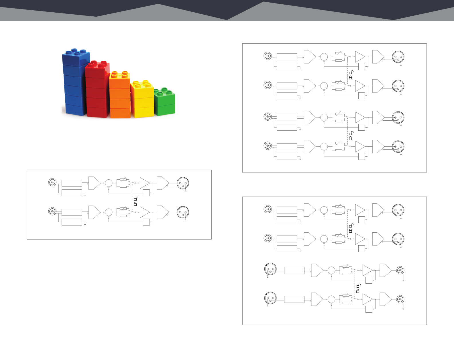
No? You meant the boring kind of diagram? Sorry.
Here’s a look at the signal flow through the Stereo Balancing Gadget:
1L GAIN
∑
PWR
AMP
231
LEFT PRO
OUTPUT
∫
1R GAIN
∑
MODE 1
PWR
AMP
231
RIGHT PRO
OUTPUT
∫
LEFT IHF
INPUT
RIGHT IHF
INPUT
RFI FILTER
ESD CLAMP
RFI FILTER
ESD CLAMP
DIF
AMP
DIF
AMP
STEREO BALANCING GADGET FUNCTIONAL BLOCK DIAGRAM
The signal flow through the Dual Stereo Balancing Gadget:
IHF 1L
INPUT
IHF 1R
INPUT
IHF 2L
INPUT
IHF 2R
INPUT
RFI FILTER
ESD CLAMP
RFI FILTER
ESD CLAMP
RFI FILTER
ESD CLAMP
RFI FILTER
ESD CLAMP
DUAL STEREO BALANCING GADGET FUNCTIONAL BLOCK DIAGRAM
DIF
AMP
DIF
AMP
DIF
AMP
DIF
AMP
1L GAIN
∑
PWR
AMP
231
PRO 1L
OUTPUT
∫
1R GAIN
∑
MODE 1
PWR
AMP
231
PRO 1R
OUTPUT
∫
2L GAIN
∑
PWR
AMP
231
PRO 2L
OUTPUT
∫
2R GAIN
∑
MODE 2
PWR
AMP
231
PRO 2R
OUTPUT
∫
And signal flow through through the Bidirectional Stereo Balancing Gadget:
Page 10

17 Specicaons More Specs 18
Riveting data about your gadget.
Part Numbers
Stereo Balancing Gadget Part No. 991001
Dual Stereo Balancing Gadget Part No. 991002
Bidirectional Stereo Balancing Gadget Part No. 991003
For export versions, add suffix after part number: “E” for 230VAC Europe plug,
“A” for 230VAC Australia plug, “U” for 230VAC UK plug. For example, 991001E is
Stereo Balancing Gadget, 230VAC, European plug.
Unbalanced to Balanced Conversion
Fixed Gain +11.8dB (-10dBv in = +4dBu out)
Adjustable Gain Range +10dB to +28db
Frequency Response ± 0.2dB, 20Hz – 20kHz
THD+N ≤ 0.004%, 20Hz – 20kHz
Noise ≤ 90dBu (20Hz to 20kHz, fixed gain position)
Headroom ≥ 20dB
Maximum Output Level +26dBu (+24dBm @ 600Ω load)
Input Impedance 100kΩ
Output Impedance 100Ω balanced
Crosstalk ≤ -75dB (10kHz)
CMRR ≥ 70dB (20Hz to 20kHz)
Power and Environmental
North American Version 115VAC 60Hz, NEMA 5-15P power plug
Export Versions 230VAC 50/60Hz, various plugs
Power Consumption 5VA
Operating Temperature 0º to 40º C (32º to 104º F)
Storage Temperature -20º to 45º C (-4º to 113º F)
Relative Humidity 0% to 90% non-condensing
Cooling Vented chassis (fanless)
Product Weight & Dimensions
Width x depth x height 8.5 x 6.25 x 1.70 in., 21.6 x 16 x 4.32 cm.
Weight 3.5 pounds, 1.6 kilograms
Shipping Weight & Dimensions
Length x width x height 12 x 9 x 6 in., 31 x 23 x 16 cm.
Weight 5 pounds, 2.3 kilograms
Compliance
In The U.S.
Balanced to Unbalanced Conversion
Fixed Gain -11.8dB (+4dBu in = -10dBv out)
Adjustable Gain Range - -17dB to +1dB
Frequency Response ± 0.2dB (20Hz to 20kHz)
THD+N ≤ 0.004% (20Hz to 20kHz)
Noise ≤ 90dBu (20Hz to 20kHz, fixed gain position)
Headroom ≥ 20dB
Maximum Output Level +15dBv
Input Impedance 20kΩ
Output Impedance 100Ω (pseudo-balanced)
Crosstalk ≤ -75dB (10kHz)
CMRR ≥ 70dB (20Hz to 20kHz)
In the U.S., this gadget complies with the limits for a Class A computer device
as specified by FCC Rules, Part 15, Subpart J, which are designed to provide
reasonable protection against such interference when this type of equipment is
operated in a commercial environment.
In Canada
In Canada, this gadget does not exceed the Class A limits for radio noise
emissions set out in the Radio Interference Regulations of the Canadian
Department of Communications.
In Europe
This gadget complies with the requirements of the EEC Council Directives
93/68/EEC (CE Marking), 73/23/EEC (safety – low voltage directive), and
89/336/EEC (electromagnetic compatibility). Conformity is declared to standards
EN50081-1 and EN50082-1
Page 11

19 Schemacs Schemacs 20
A peek deep inside the Stereo Balancing Gadget.
Page 12
21 Schemacs Schemacs 22
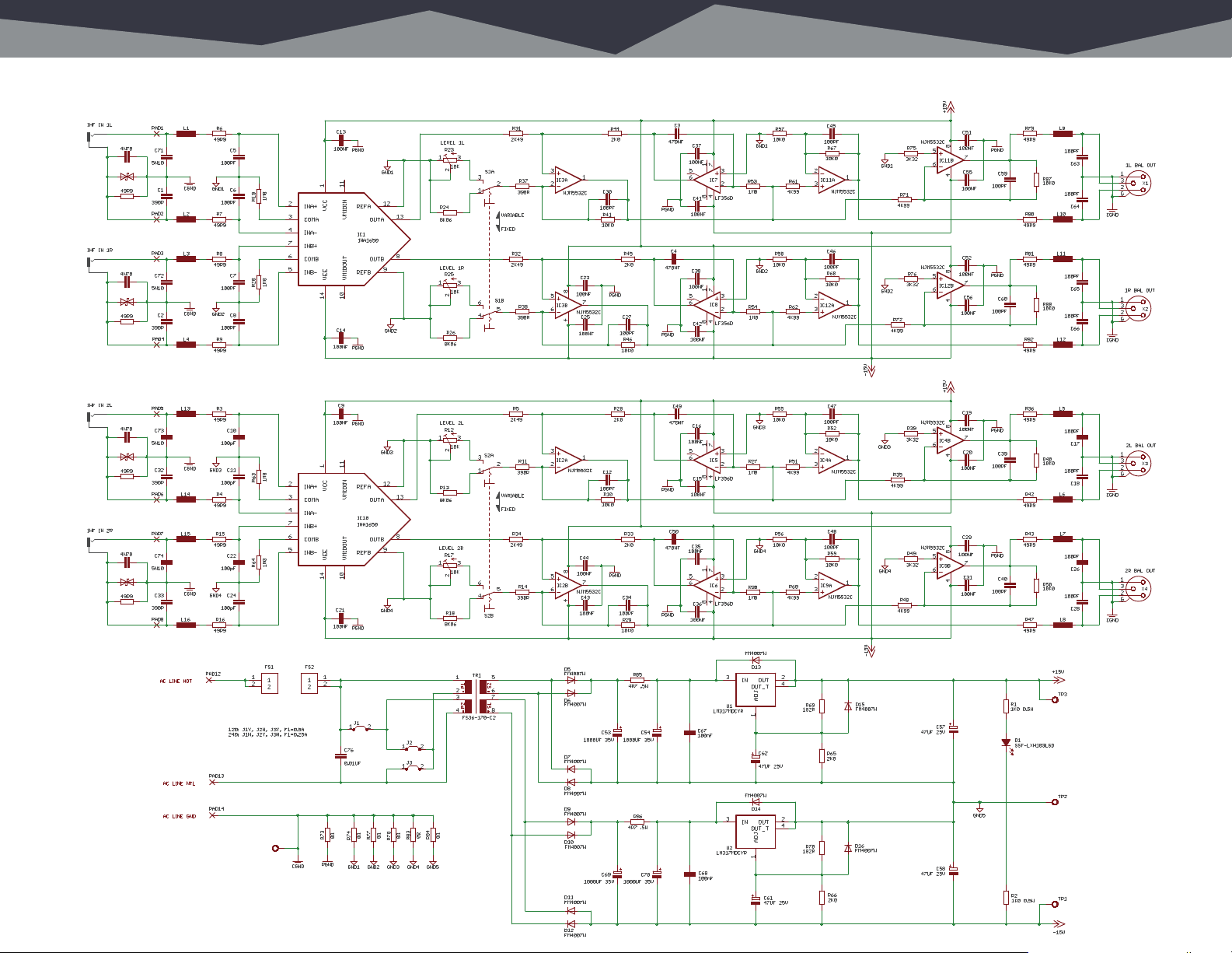
Dual Stereo Balancing Gadget.
Page 13
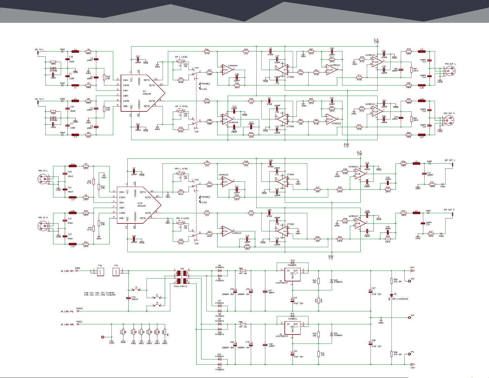
23 Schemacs Schemacs 24
Bidirectional Balancing Gadget.
 Loading...