

Page 1
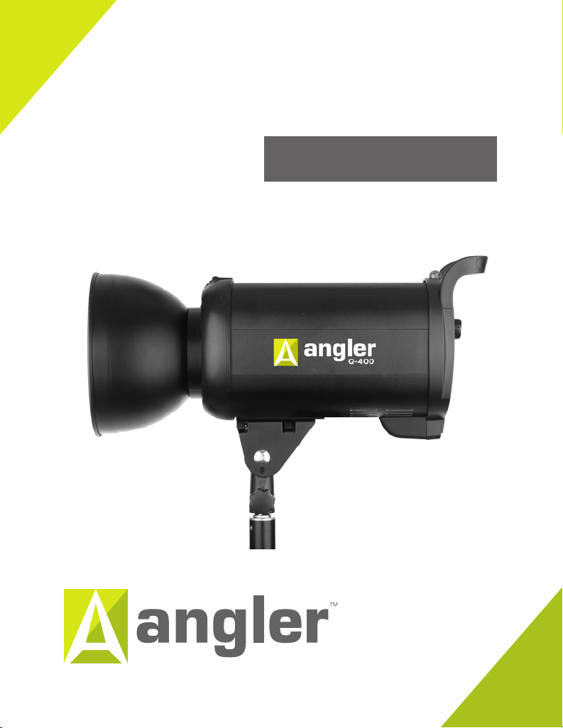
monolight
Q-400
INSTRUCTIONS
INSTRUCTIONS
Page 2

Introduction
Congratulations on your purchase of the Angler Silver 18˝ softbox!
The Angler Q-400 Monolight can be used for everything from professional wedding and portrait
work to action and sports photography. This monolight is an easy-to-use and reliable tool built
for functionality, and it incorporates advanced features that are engineered for speed. You can
work fast and uninterrupted with the Q-400, capturing amazing moments as they happen.
Ideal for working professionals, the Q-400 is designed so you’ll never miss a shot while waiting
for your light to recycle. Recycling time is as fast as 0.4 seconds at full power, flash duration is
as low as 1/5000 of a second, and continuous shooting speed can reach a blistering 10 frames
per second. This spectacular speed makes the Q-400 great not just for fashion and event
shooting, but also for high-speed photography. The Q-400 is fast enough to capture almost
any movement at its peak, whether it’s a cork bursting from a champagne bottle, or it’s a pitcher
hurling a fastball.
Because high-speed flash photography can often mean high temperatures, the Q-400
uses a fan-cooling system, heat sinks, and speed-dedicated internal components to prevent
overheating.
This monolight is easy to accessorize. With its built-in umbrella mount and Bowens S-type
bayonet, you’ll be able to attach light modifiers like beauty dishes, softboxes, and umbrellas to
customize and shape your light to achieve the perfect look. A modeling lamp with a stepless
power-output setting makes it easy to check positioning of your flash before it’s time to fire.
The Q-400 has an optical sensor, so you can use it as an optical slave. There’s also the optional
Angler RC-16 transmitter and receiver, which provide 150’ (50 m) of untethered freedom with
total wireless control over the Q-400.
1
Page 3
Precautions
Please read and follow these instructions, and keep this manual in a safe place.
Keep this unit away from water and any flammable gases or liquids.
Do not leave the device in a closed vehicle under the sun or in other areas subject to very
high temperatures.
Do not attempt to disassemble or repair the equipment. There are high-voltage
components inside the unit. Failure to observe this precaution could result in electric
shock or product malfunction. This will void the warranty, and Angler will not be
responsible for any damage.
Use only the correct, recommended voltage.
Make sure the unit is powered o when plugging it into a power source.
Always remove the power cord by holding the plug; do not pull the cord.
Disconnect the power cord from the power supply when not in use.
Always power o and disconnect the flash from the power supply before changing the
modeling lamp or flashtube.
Do not stare directly at the lights when they are powered on.
Do not flash directly towards the naked eye (especially those of infants and small
children)—it may lead to visual impairment.
Always remove the transport cap before using the flash.
Avoid any unnecessary impact to the flash, as this can damage the flashtube and/or
modeling lamp.
Use only parts provided by the manufacturer.
Handle the unit with care.
Clean the unit with a soft, dry cloth.
Keep this unit away from children.
Make sure the item is intact and that there are no missing parts.
All photos are for illustrative purposes only.
2
Page 4

Table of Contents
Introduction �����������������������������������������������������������������������������������������������������������1
Precautions ���������������������������������������������������������������������������������������������������������2
Overview ������������������������������������������������������������������������������������������������������������ 4
Mounting the Q-400 ������������������������������������������������������������������������������������7
Setting Flash Power Output �����������������������������������������������������������������������������10
Using the Modeling Lamp ���������������������������������������������������������������������������������� 11
Audio Confirmation �������������������������������������������������������������������������������������������� 11
Mounting Accessories ���������������������������������������������������������������������������������������12
The Accessory Mount ����������������������������������������������������������������������������������� 12
The Umbrella Mount �������������������������������������������������������������������������������������13
Adjusting the Center of Gravity ������������������������������������������������������������������14
Triggering the Flash ��������������������������������������������������������������������������������������������15
1/4″ Phono ����������������������������������������������������������������������������������������������������� 15
Wireless Optical Slave �����������������������������������������������������������������������������������15
Wireless Remote Control �����������������������������������������������������������������������������15
Replacing Parts ��������������������������������������������������������������������������������������������������16
Replacing the Flashtube �������������������������������������������������������������������������������16
Replacing the Fuse ���������������������������������������������������������������������������������������� 17
Specifications �����������������������������������������������������������������������������������������������������18
One-Year Limited Warranty ����������������������������������������������������������������������������� 19
3
Page 5
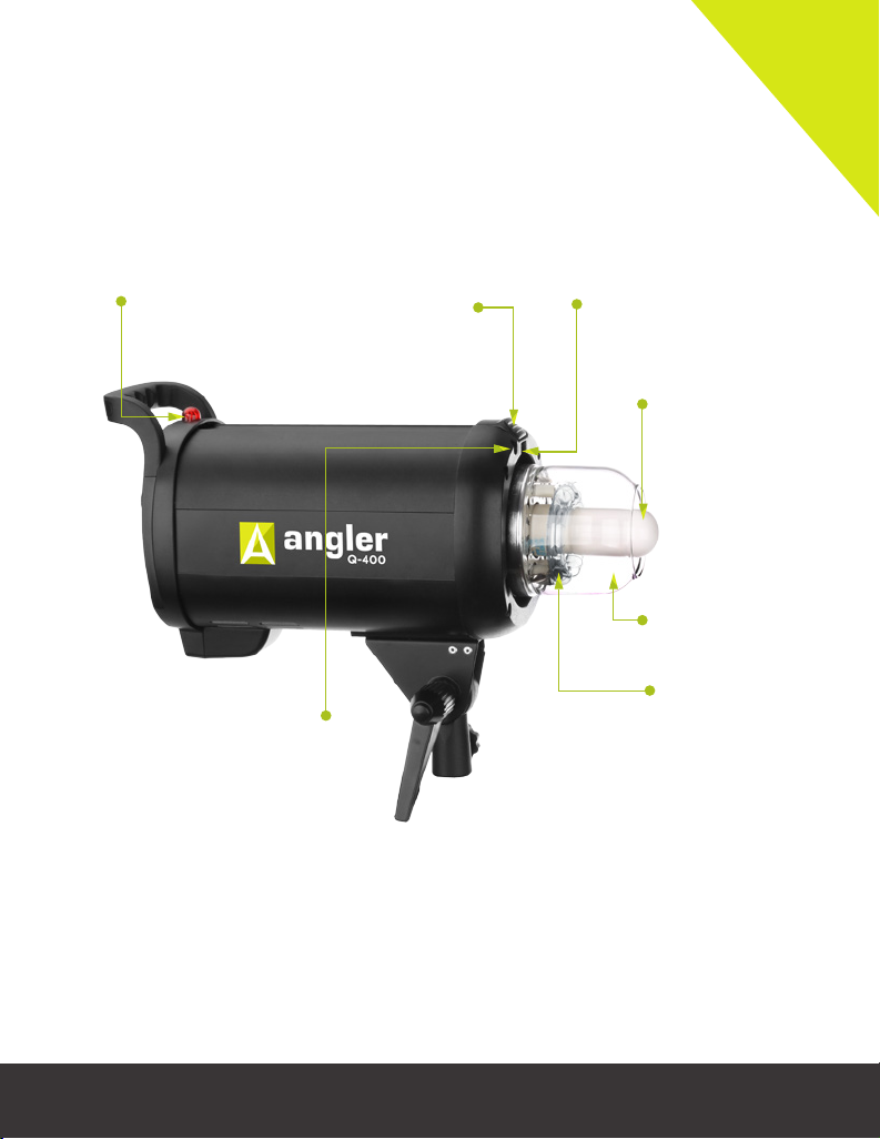
Overview
Optical slave
sensor
Umbrella mount
(front)
Accessory release
latch
Bayonet accessory
mount
Modeling lamp
Protective glass
dome
Flashtube
4
Page 6
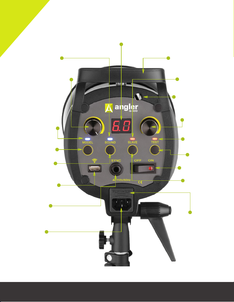
LCD display
Sound indicator
light
Modeling lamp output
control dial
Modeling lamp
indicator light
Modeling lamp
button
Sound button
Wireless remote
port
1/4
″ phono
socket
Adjustment/carry
handle
Slave indicator
light
Umbrella mount
(rear)
Flash output
control dial
Flash ready
indicator light
Flash test
button
Power Switch
Slave mode
button
Fuse bay
5
AC power
socket
Page 7

Ratchet handle
Mounting bracket
Locking knob
Hex screw
Mounting bracket
positioning rails
Also Included:
Mounting bracket
positioning rails
Protective glass dome
Transport cover
7″ grid reflector
AC power cord
PC sync to 1/4″phono cord
Spare fuse
User manual
6
Page 8

Getting Started
Mounting the Q-400
1.
Make sure the mounting bracket’s ratchet
handle is fully tightened.
2.
Loosen the locking knob on the mounting
socket and mount the Q-400 onto your
lightstand.
3. Tighten the locking knob until secure.
You can adjust the tilt of the monolight by
loosening the ratchet handle. Make sure to keep
one hand on the monolight to hold it steady to
avoid damaging the light.
1
7
Page 9

Setting Up
After mounting the Q-400 on your lightstand,
you will need to install the modeling lamp and the
reflector.
Important! Do not touch the modeling lamp or
flashtube with your bare hands. Oil residue from
your fingers can cause the surface of the flashtube
to heat unevenly and explode. Always wear cotton
gloves or use a clean cloth when handling the
modeling lamp or flashtube.
To install the modeling lamp, follow these steps:
1. Make sure that the monolight is turned o and
unplugged.
2.
Remove the transport cover by pulling the
accessory release latch and rotating the
transport cover counterclockwise.
3. Remove the protective glass dome by carefully
pulling it from the clips holding it in place.
4.
Screw the modeling lamp into the threaded
socket.
2
3
4
5.
Reinstall the protective glass dome by snapping
it in place over the two bulbs.
8
Page 10

To install the reflector, follow these steps:
1.
Align the three pegs on the reflector with
the corresponding notches in the monolight’s
bayonet accessory mount.
Note: Make sure the reflector’s umbrella hole
is aligned with the monolight’s umbrella mount,
located next to the accessory release latch.
2.
Insert the reflector into the accessory mount
and rotate the reflector clockwise until it locks
into place.
The Q-400 runs on the standard 110 V AC, 60 Hz
voltage and comes with a grounded AC power cord.
To plug in the Q-400, follow these steps:
1.
Make sure the power switch is set to the O
position.
2.
Plug the AC power cord into the monolight’s
AC power socket and then into an AC power
outlet.
1
2
9
Page 11

Setting Flash Power Output
The Q-400’s flash power output covers a 6-stop
range. It is adjusted via the flash power output
control from 6.0 (full power) all the way down to
1.0, in 0.1-stop increments. The selected flash power
is displayed on the LCD.
Note: Turning the flash power output lower than
1.0 until “OF” is displayed on the LCD will disable
flash firing. This feature is for use with the dedicated
remote. For more information, see the Wireless
Remote Control section in Triggering the Flash on
page 15.
To fire a test flash, press the flash test button. When
the flash has recycled and is ready for another flash,
the flash ready indicator light will glow red.
The Q-400’s autodump feature automatically
empties the capacitor to the required power setting
when you lower the flash output.
There is a built-in memory function that saves the
settings on the control panel after 3 seconds. The
next time you turn on the Q-400, your previous
settings will appear on the control panel.
Note: After 30 continuous flashes at full power, the
flash should be cooled down for about 3 minutes.
Overheating may occur if it is used continuously
without cooling down.
10
Page 12

Using the Modeling Lamp
The modeling lamp is a continuous light that you can use for flash positioning to give you an idea
of how the flash will illuminate your subject.
To turn on the modeling lamp, press the modeling lamp button. When the modeling lamp is on,
the modeling lamp indicator light will glow blue. Use the modeling lamp output control dial to
steplessly adjust power output.
If the modeling lamp is on when you fire the flash, the modeling lamp will dim and then return
to its set power output level after the flash has fully recycled.
Note: The modeling lamp will automatically turn o after 2 hours to avoid overheating.
Audio Confirmation
The Q-400 can emit a beep to let you know when the flash has fully recycled and is ready for
another flash. This feature is useful when you can’t see the flash ready indicator light, which
indicates the status of the flash. The audio confirmation will also cause the monolight to emit a
beep when you press any of the buttons or rotate the flash output control dial.
To turn on audio confirmation, press the sound button. The sound indicator light will glow blue
when audio confirmation is turned on.
11
Page 13

Mounting Accessories
The Accessory Mount
The Q-400 has a Bowens S-type bayonet accessory
mount for attaching light-shaping tools like
softboxes, beauty dishes, and snoots, as well as the
included 7″ reflector with an umbrella hole.
Important! To avoid potential damage, do not leave
the modeling lamp turned on for an extended period
of time when using a heat-sensitive accessory.
To mount an accessory, follow these steps:
1.
Align your accessory’s mounting pegs with
the corresponding notches on the monolight’s
accessory mount.
2.
Insert your accessory into the accessory mount
and rotate your accessory clockwise until it locks
into place.
To remove the accessory, pull the accessory release
latch and rotate the accessory counterclockwise.
12
Page 14

The Umbrella Mount
The Q-400 has an integrated umbrella mount that
employs an internal tension spring capable of holding
up to a 7″ parabolic umbrella.
To mount an umbrella in the Q-400, insert your
umbrella shaft into the umbrella mount at the front
of the monolight. Depending on the desired position
of your umbrella and the length of its shaft, the shaft
may emerge from the umbrella mount at the rear
of the monolight.
13
Page 15

Adjusting the Center of Gravity
The Q-400 has an adjustable mounting bracket
held in place by a single hex screw. This makes it
easy to adjust the monolight’s center of gravity if a
large or heavy accessory is causing it to tilt forward
or backward.
To adjust the monolight’s center of gravity, follow
these steps:
1.
Turn o and unplug the Q-400 and remove any
mounted accessories.
2.
Use a 3 mm hex wrench to loosen the hex screw
in the mounting bracket.
3.
Slide the mounting bracket forward or backward
along its positioning rails to the desired position.
4.
Tighten the hex screw until secure. The
Q-400’s center of gravity is now adjusted for
a large accessory.
2
3
4
14
Page 16

Triggering the Flash
There are three ways to trigger the flash: 1/4″ phono, optical slave, or wireless remote (sold
separately). When you trigger the flash, the flash ready indicator light will turn o and then turn
on when the flash has recycled and is ready for another flash. If audio confirmation is activated,
the monolight will emit a beep when the flash has fully recycled.
1/4″ Phono
To trigger via a 1/4″ phono cord, use the included PC sync to 1/4″ phono cord to connect your
camera’s PC sync terminal to the Q-400’s 1/4″ phono socket. A remote slave receiver can
also be plugged into this socket.
Wireless Optical Slave
The Q-400 is equipped with a wireless optical slave feature, allowing you to fire the monolight
remotely. There are two slave modes on the Q-400: Instant-Fire and Skip Preflash.
Instant-Fire slave mode fires the monolight as soon as it sees a flash. Skip Preflash mode ignores
the preflash from the master and fires only with the main flash.
To set the slave mode, press the slave button repeatedly until the slave indicator light turns the
proper color. In Instant-Fire mode the slave indicator light will glow blue, and in Skip Preflash
mode the indicator will glow red.
Note: When positioning wireless slaves to light a subject, make sure to maintain a clear line
of sight between the master and the optical slave sensor. Keep in mind that the eective
communication range between master and slave flash units is approximately 33′ (10 m).
Wireless Remote Control
A dedicated remote control, the Angler RC-16 transmitter and receiver (sold separately), can
control triggering, adjust power levels, and turn the modeling light and audio confirmation
features on and o. To use the remote, plug the dedicated receiver into the monolight’s USB
wireless remote port.
15
Page 17

Replacing Parts
Replacing the Flashtube
Important! Before replacing the flashtube, it is
recommended to manually empty the capacitor (see
below), even though the Q-400 has an autodump
feature.
To replace the flashtube, follow these steps:
Note: When handling the flashtube, use a clean
cloth or cotton gloves. Never touch the flashtube
with your bare hands. Oil residue from your fingers
can cause the surface of the lamp to heat unevenly
and explode.
1.
Manually empty the capacitor by pressing the
test button to fire the flash. Immediately turn
o the monolight by pressing the power switch
to the O position.
2.
Unplug the AC power cable from the
monolight’s AC power socket.
3.
Remove the reflector, glass dome, and modeling
lamp.
4
5
4.
Carefully loosen the metal wire wrapped around
the flashtube. Needle-nose pliers may be helpful
for this.
5.
Hold both sides of the base of the flashtube
and firmly pull the flashtube straight out of the
socket.
16
Page 18

6.
Insert a fresh flashtube into the flashtube socket.
7.
Wrap the metal wire around the clip that holds
the flashtube in place. The wire does not need
to be in the exact position as before, but it does
need to connect the two ends of the clip.
8.
Reinstall the modeling lamp, glass dome, and
reflector.
Replacing the Fuse
The Q-400’s user-replaceable fuse protects the
flash unit’s circuitry. The fuse and included spare
are located in a bay mounted above the AC plug.
To replace the fuse, follow these steps:
1.
Turn off the Q-400 by pressing the power
switch to the O position.
Unplug the AC power cable from the
2.
monolight’s AC power socket.
3.
Use a flat-head screwdriver or needle-nose
pliers to remove the fuse bay.
4. Remove the old fuse (a) and replace it with the
a
spare (b).
5. Reinsert the fuse bay into the monolight.
17
b
3
4
Page 19

Specifications
Maximum power 400 Ws
Recycle time 0.4 sec. at full power
Flash duration 1/5000 to 1/800 sec.
Power output
control
Guide number
(ISO 100)
Color temperature 5600 K ±100 K
Modeling lamp
maximum output
Operating voltage 110 V AC, 60 Hz
Triggering method
Circuit protection 8A fuse
Accessory mount Bowens S-type
Umbrella mount 0.31 (8 mm)
Sync terminal
Dimensions
(without
reflector)
Weight (with
flashtube,
modeling lamp, and
reflector)
6-stop range, 6.0 to 1.0 in 0.1-
stop increments
′ (65 m)
213
150 W (E27 base, user
replaceable)
Test button, sync cord, optical
slave, wireless remote port
″ phono
1/4
″ × 5.5″ × 5.5″
16.1
(41 × 14 × 14 cm)
7.15 lb. (3.24 kg)
18
Page 20

One-Year Limited Warranty
ANGLER
A Gradus Group
Brand
TM
This Angler product is warranted to the original purchaser to be free from defects in materials and
workmanship under normal consumer use for a period of one (1) year from the original purchase date
or thirty (30) days after replacement, whichever occurs later. The warranty provider’s responsibility
with respect to this limited warranty shall be limited solely to repair or replacement, at the provider’s
discretion, of any product that fails during normal use of this product in its intended manner and in
its intended environment. Inoperability of the product or part(s) shall be determined by the warranty
provider. If the product has been discontinued, the warranty provider reserves the right to replace it
with a model of equivalent quality and function.
This warranty does not cover damage or defect caused by misuse, neglect, accident, alteration, abuse,
improper installation or maintenance. EXCEPT AS PROVIDED HEREIN, THE WARRANTY
PROVIDER MAKES NEITHER ANY EXPRESS WARRANTIES NOR ANY IMPLIED
WARRANTIES, INCLUDING BUT NOT LIMITED TO ANY IMPLIED WARRANTY OF
MERCHANTABILITY OR FITNESS FOR A PARTICULAR PURPOSE. This warranty provides you
with specific legal rights, and you may also have additional rights that vary from state to state.
To obtain warranty coverage, contact the Angler Customer Service Department to obtain a return
merchandise authorization (“RMA”) number, and return the defective product to Angler along with
the RMA number and proof of purchase. Shipment of the defective product is at the purchaser’s own
risk and expense.
For more information or to arrange service, visit www.anglerlights.com or call Customer Service at
212-594-2353.
Product warranty provided by the Gradus Group.
www.gradusgroup.com
Angler is a registered trademark of the Gradus Group.
© 2015 Gradus Group LLC. All Rights Reserved.
GG1
 Loading...