

Page 1

OPTIMO STYLE 30-76 I
USER’S MANUAL
MANUEL UTILISATEUR
Page 2

OPTIMO STYLE 30-76
Page 3

Page 4

Page 5

OPTIMO STYLE 30-76
USER’S MANUAL
MANUEL UTILISATEUR
Référence : 317 383 B Edition : Juin 2014
Page 6

This document with confidential information is THALES ANGENIEUX property,
it cannot be reproduced nor communicated to anybody without a written
authorization from a person especially chosen by THALES ANGENIEUX.
Ce document qui contient des informations confidentielles est la propriété
THALES ANGENIEUX, il ne peut être ni reproduit, ni communiqué à des tiers
sans autorisation écrite d’une personne mandatée spécialement à cet effet par
THALES ANGENIEUX.
6 OPTIMO STYLE 30-76
Page 7

CONTENTS / SOMMAIRE
1 - GENERAL SPECIFICATIONS 9
SPECIFICATIONS GÉNÉRALES 9
2 - INSTALLATION 13
INSTALLATION
3 - MAINTENANCE 17
MAINTENANCE
4 - OUTLINE VIEW 23
VUE EXTÉRIEURE 23
5 - BACK FOCUS AND TRACKING ADJUSTMENT 27
RÉGLAGE DU TIRAGE ET DU TRACKING
6 - PANAVISION MOUNT 35
MONTURE PANAVISION
7 - OUTLINE DRAWING 39
PLAN D’ENCOMBREMENT
13
17
27
35
39
CONTENTS I SOMMAIRE OPTIMO STYLE 30-76 7
Page 8

OPTIMO STYLE 30-76
Page 9

GENERAL SPECIFICATIONS
SPECIFICATIONS GÉNÉRALES
9
Page 10

1 - GENERAL SPECIFICATIONS
Angénieux OPTIMO STYLE 30-76
Zoom ratio 2.5x
Focal length 30-76 mm
Aperture T2.8 – F/2.6
Minimum Object Distance (MOD) 0.6 m – 2’
Image coverage S 35 + : 31.4 mm diagonal
Weight 1.92 kg - 4.2 lbs
Front diameter 114 mm
Iris scales 2 opposite scales, whole and 1/3 stop marked
Angular rotation of iris ring 85 degrees
Iris gear drive 105 teeth, pitch 32
Zoom scales 2 opposite scales
Angular rotation of zoom ring 155 degrees
Zoom gear drive 105 teeth, pitch 32
Focus scales 2 opposite scales, metric or footage marked
Angular rotation of focus ring 320 degrees
Focus gear drive 111 teeth, pitch 32
Angular field of view (for 35mm academic film size: 22x16mm)
Focal length 30 mm 76 mm
Horizontal angular field of view 40.2° 16.4°
Object size at MOD 321x232 mm 126x92 mm
10 OPTIMO STYLE 30-76 1 - GENERAL SPECIFICATIONS
Page 11

1 - SPÉCIFICATIONS GÉNÉRALES
Angénieux OPTIMO STYLE 30-76
Zoom ratio 2.5x
Focale 30-76 mm
Ouverture T2.8 – F/2.6
Distance minimum 0.6 m – 2’
Format d’image couvert S 35 + : 31.4 mm de diagonale
Poids (approx.) 1.92 kg - 4.2 lbs
Diamètre avant 114 mm
Gravure d’iris 2 marquages opposés, pas entiers et 1/3 de pas
Angle de rotation de l’iris 85 degrés
Pignon d’engrenage iris 105 dents, pitch 32
Gravures focales 2 marquages opposés
Angle de rotation focale 155 degrés
Pignon d’engrenage focale 105 dents, pitch 32
Gravure Mise Au Point 2 marquages opposés, mètres ou pieds
Angle de rotation MAP 320 degrés
Pignon d’engrenage MAP 111 dents, pitch 32
Angle de champs (pour film 35mm : 22x16mm)
Focale 30 mm 76 mm
Angle de champs horizontal 40.2° 16.4°
Dimensions objet à la distance minimum 321x232 mm 126x92 mm
1 - SPÉCIFICATIONS GÉNÉRALES OPTIMO STYLE 30-76 11
Page 12

LENS POLISHING /
POLISSAGE D’UNE LENTILLE
Page 13

INSTALLATION
INSTALLATION
13
Page 14

Page 15

2 INSTALLATION
2 INSTALLATION
2.1 Installation on the camera
Remove the front and rear cap.
Make sure the PL or PV mount on the lens and on the camera are perfectly clean.
Mount the lens on the camera.
Install the accessories around the lens (matte box, motors…).
When using a zoom or focus motor mounted on rods, it’s recommended to install
the lens bracket with a standard lens support unit.
2.2 Focus
The mechanical flange is setup at 52 mm in the air for perfect focus at wide angle.
If needed, flange can be adjusted (see Flange adjustment § 5.2).
The focus marks are calibrated at ambient temperature for optimized focus at long
focal length.
There is a small shift on the marks when using the lens at very high or low
temperatures.
2.1 Installation sur camera
Retirez les capuchons avant et arrière.
Assurez vous que la monture de l’objectif et de la caméra soient parfaitement
propres.
Montez l’objectif sur la caméra.
Installez les accessoires annexes à l’objectif (matte box, moteurs,…)
Quand vous utilisez une motorisation sur la bague de commande focale ou de
mise au point, il est recommandé de monter l’objectif sur pied avec un support
standard.
2.2 Mise au point
Le tirage mécanique est réglé à 52 mm pour une mise au point parfaite à la
courte focale.
Si besoin, le tirage peut être repris (voir § 5.2 Réglage du tirage).
Les gravures de la mise au point sont calibrées à température ambiante pour un
réglage optimisé à la longue focale.
Il existe un léger décalage sur les gravures lorsqu’on utlise l’objectif à des
températures très hautes ou très basses.
2 - INSTALLATION OPTIMO STYLE 30-76 15
Page 16

MAINTENANCE OPERATION /
OPÉRATION DE MAINTENANCE
Page 17

MAINTENANCE
MAINTENANCE
17
Page 18

3 MAINTENANCE
3.1 Cleaning
For maximum image quality, make sure the front and the rear optics are clean,
free of stain and dust. Use an optical cleaning solution and a soft tissue to
remove fingerprints from the optics.
3.2 Lubrication
3.4 Advance maintenance
The complete maintenance of such a lens should only be performed by highly
qualified people or factory trained technicians.
If you are uncertain of your capabilities to do the repair, feel free to send the lens
to our THALES ANGENIEUX After Sales Service. Our qualified technicians will
ensure proper handling of all maintenance and repair related items.
In addition, THALES ANGENIEUX can offer preventive maintenance operations to
always keep your lens in perfect conditions.
The zoom, focus and iris mechanism are factory lubricated. If the lens has been
stored for a long time or when used in cold environment, move each function
several times before using the lens.
3.3 Moisture
To prevent humidity getting inside the lens, protect the lens to keep it dry.
18 OPTIMO STYLE 30-76 3 - MAINTENANCE
Feel free to contact us :
France and International customer support at :
Americas customer support at :
Page 19

3 MAINTENANCE
3.1 Nettoyage
Pour une qualité d’image maximale, vérifiez que les lentilles avants et arrières
soient propres et sans poussières. Utilisez un liquide de nettoyage approprié aux
optiques ainsi qu’un tissu doux pour enlever les empreintes de doigts sur les
lentilles.
3.2 Graissage
Les mécanismes de focale, mise au point et d’iris sont lubrifiés en usine. Si
l’objectif a été stocké longtemps ou s’il va être utilisé dans le froid, manoeuvrez
plusieurs fois les mécanismes avant usage.
3.3 Humidité
Pour éviter que l’objectif prenne l’humidité, protégez le afin de le garder au sec.
3.4 Maintenance avancée
La maintenance complète de ce type d’objectif ne peut être effectuée que par
des personnes hautement qualifiées et formées par THALES ANGENIEUX.
Si vous avez un doute sur votre capacité à effectuer cette réparation, n’hésitez
pas à confier le produit au Service Après-Ventes de THALES ANGENIEUX. Vous
aurez ainsi la garantie d’avoir un produit parfaitement réparé.
En outre, THALES ANGENIEUX peut vous proposer des actions de maintenance
préventive afin de toujours maintenir votre produit à son meilleur niveau.
Veuillez nous contacter à :
3 - MAINTENANCE OPTIMO STYLE 30-76 19
Page 20

3.5 MAINTENANCE ITEMS
Description Spanner Retaining ring or screws Locking torque
Flange shim retaining ring spanner 197 655 301 146 (16) 1.5 Nm
Tracking ring retaining ring spanner 197 654 301 144 (17) 1.5 Nm
Tracking adjustment Allen key Allen key 0.9 mm 987 018 (13)
Iris retaining ring spanner 197 659 313 450 (12)
20 OPTIMO STYLE 30-76 3 - MAINTENANCE
Page 21

3.5 ARTICLES POUR LA MAINTENANCE
Description Référence de la clé Référence de l’écrou ou de la vis Couple de serrage
Clé pour écrou des rondelles de tirage 197 655 301 146 (16) 1.5 Nm
Clé pour écrou de la bague de tracking 197 654 301 144 (17) 1.5 Nm
Clé pour vis de réglage du tracking Clé six pans 0.9 mm 987 018 (13)
Clé pour écrou de commande iris 197 659 313 450 (12)
3 - MAINTENANCE OPTIMO STYLE 30-76 21
Page 22

HIGH PRECISION THREE-DIMENSIONAL MEASUREMENT /
MESURE TRIDIMENSIONNELLE DE PRECISION
Page 23

OUTLINE VIEW
VUE EXTERIEURE
23
Page 24
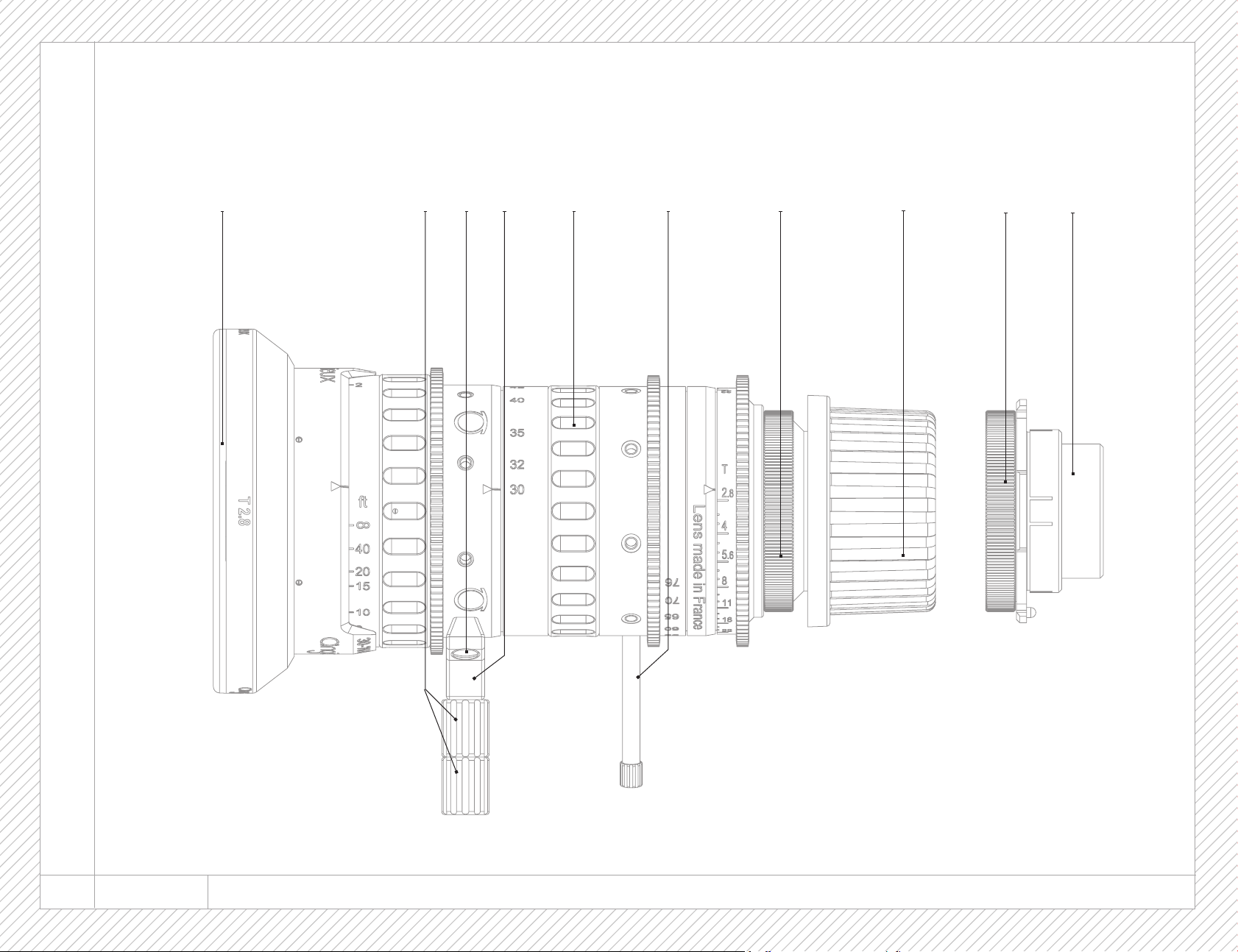
Picture 1
Figure 1
31 4 5 6 7 8
2
9
10
24 OPTIMO STYLE 30-76 4 - OUTLINE VIEW I VUE EXTÉRIEURE
Page 25

4 - OUTLINE VIEW
Reference P/N Description Quantity
1 311 819 Front cap 1
2 217 190 Intermediate bracket 2
3 993 757 Screws for bracket 2
4 301 373 Lens bracket 1
5 311 364 Zoom rubber ring 1
6 212 926 Zoom lever 1
7 315 655 PL mount subassembly (in PL configuration) 1
8 311 816 PL mount cap (in PL configuration) 1
9 301 181 Panavision mount subassembly (in Panavision configuration) 1
10 301 342 Panavision mount cap (in Panavision configuration) 1
- 309 148 Canon mount (optional) -
- 309 150 Nikon mount (optional) -
4 - VUE EXTÉRIEURE
Référence P/N Désignation Quantité
1 311 819 Bouchon avant 1
2 217 190 Rallonge de pied 2
3 993 757 Vis du support d’objectif 2
4 301 373 Support d’objectif 1
5 311 364 Bague crantée focale 1
6 212 926 Levier focale 1
7 315 655 Sous-ensemble monture PL (en configuration PL) 1
8 311 816 Bouchon de la monture PL (en configuration PL) 1
9 301 181 Sous-ensemble monture Panavision (en configuration Panavision) 1
10 301 342 Bouchon de la monture Panavision (en configuration Panavision) 1
- 309 148 Monture Canon (en option) -
- 309 150 Monture Nikon (en option) -
4 - OUTLINE VIEW I VUE EXTÉRIEURE OPTIMO STYLE 30-76 25
Page 26

LONG DISTANCE (131 FT) PROJECTION ROOM /
SALLE DE PROJECTION LONGUE DISTANCE (40M)
Page 27

BACK FOCUS AND TRACKING ADJUSTMENT
RÉGLAGE DU TIRAGE ET DU TRACKING
27
Page 28
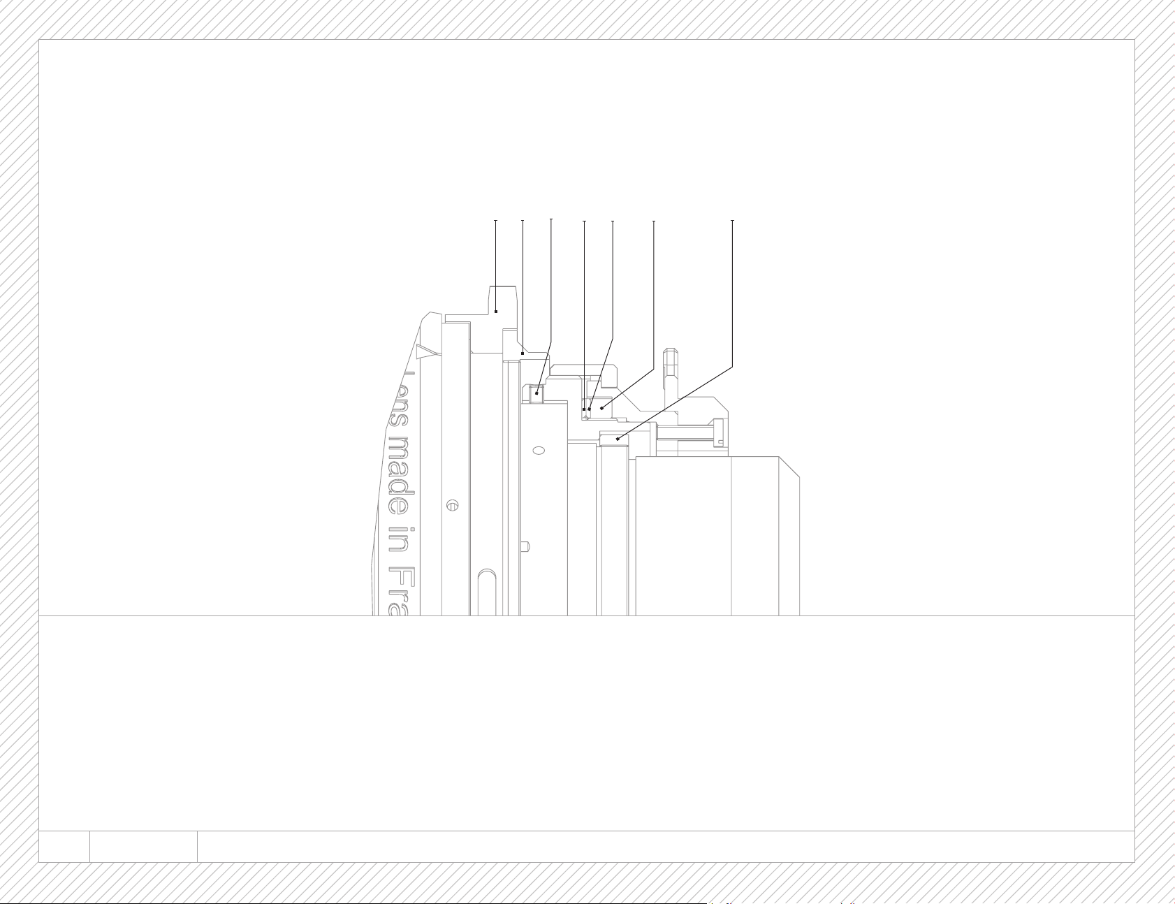
Picture 2
Figure 2
11
14 15 16
17
13
12
28 OPTIMO STYLE 30-76 5 - BACK FOCUS AND TRACKING ADJUSTMENT I RÉGLAGE DU TIRAGE ET DU TRACKING
Page 29

5.1 REAR GROUP VIEW
Reference P/N Description Quantity
11 301 174 Iris engraved ring 1
12 313 450 Iris retaining ring 1
13 987 018 Tracking adjustment screws 4
14 301 145 Flange aluminium shim 1
15 301 206 Flange peeling shim 1
16 301 146 Flange shim retaining ring 1
17 301 144 Tracking ring retaining ring 1
5.1 VUE DU GROUPE ARRIÈRE
Référence P/N Désignation Quantité
11 301 174 Bague de commande d’iris gravée 1
12 313 450 Ecrou de commande iris 1
13 987 018 Vis de réglage du tracking 4
14 301 145 Rondelle de tirage aluminium 1
15 301 206 Rondelle de tirage pelable 1
16 301 146 Ecrou des rondelles de tirage 1
17 301 144 Ecrou de la bague de tracking 1
5 - BACK FOCUS AND TRACKING ADJUSTMENT I RÉGLAGE DU TIRAGE ET DU TRACKING OPTIMO STYLE 30-76 29
Page 30

5.2 FLANGE/BACK-FOCUS ADJUSTMENT
5.2 RÉGLAGE DU TIRAGE
Although the mechanical flange is set for the standard PL mount at 52.00
mm in the air, the flange can be adjusted by modifying the thickness of the
flange shim (15).
The flange can be adjusted using a collimator or a projector.
When using a projector, proceed as following:
- Put the lens on a projector with a PL mount interface
- Put the projector at approximately 1.8 m (6 ft) from the screen
- Set the iris at T:2.8
- Optimize the focus at long focal length
- Then, zoom to wide angle
- If the best focus plan is between the screen and the lens, it is necessary to
decrease the thickness of the shim (15)
- If the best focus plan is behind the screen, it is necessary to increase the
thickness of the shim (15)
To replace the flange shim (15):
- Remove the PL mount (7) (Picture 3)
- Remove the retaining ring (16) with the spanner 197 655 (Picture 4)
- Install the new shim (15) (Picture 5)
- Reinstall the retaining ring (16) with the spanner 197 655
- Reinstall the PL mount (7)
Bien que le tirage mécanique soit réglé à 52 mm pour les montures
standard PL, il peut être ajusté en modifiant l’épaisseur de la rondelle
pelable (15).
Le tirage peut-être reglé à l’aide d’un collimateur ou d’un projecteur.
Avec un projecteur, procéder de la manière suivante :
- Monter l’objectif sur une lanterne de projection équipée d’un vérificateur PL
- Positionner le projecteur à une distance de 1.8 m environ de l’écran
- Positionner l’iris à pleine ouverture
- Faire la meilleure MAP à la longue focale
- Puis se mettre à la courte focale :
- Si le plan de meilleure MAP est entre l’écran et le zoom, il faut diminuer
l’épaisseur de la rondelle de tirage (15).
- Si le plan de meilleure MAP est derrière l’écran il faut augmenter
l’épaisseur de la rondelle de tirage.(15)
Pour changer la rondelle de tirage (15) :
- Enlever la monture PL (7) (Figure 3)
- Retirer l’écrou des rondelles de tirage (16) avec la clé 197 655 (Figure 4)
- Retirer la rondelle de tirage (15) (Figure 5)
- Modifier l’épaisseur de la cale pelable de tirage (15)
- Remonter la rondelle de tirage (15)
- Remonter la monture PL (7)
30 OPTIMO STYLE 30-76 5 - BACK FOCUS AND TRACKING ADJUSTMENT I RÉGLAGE DU TIRAGE ET DU TRACKING
Page 31
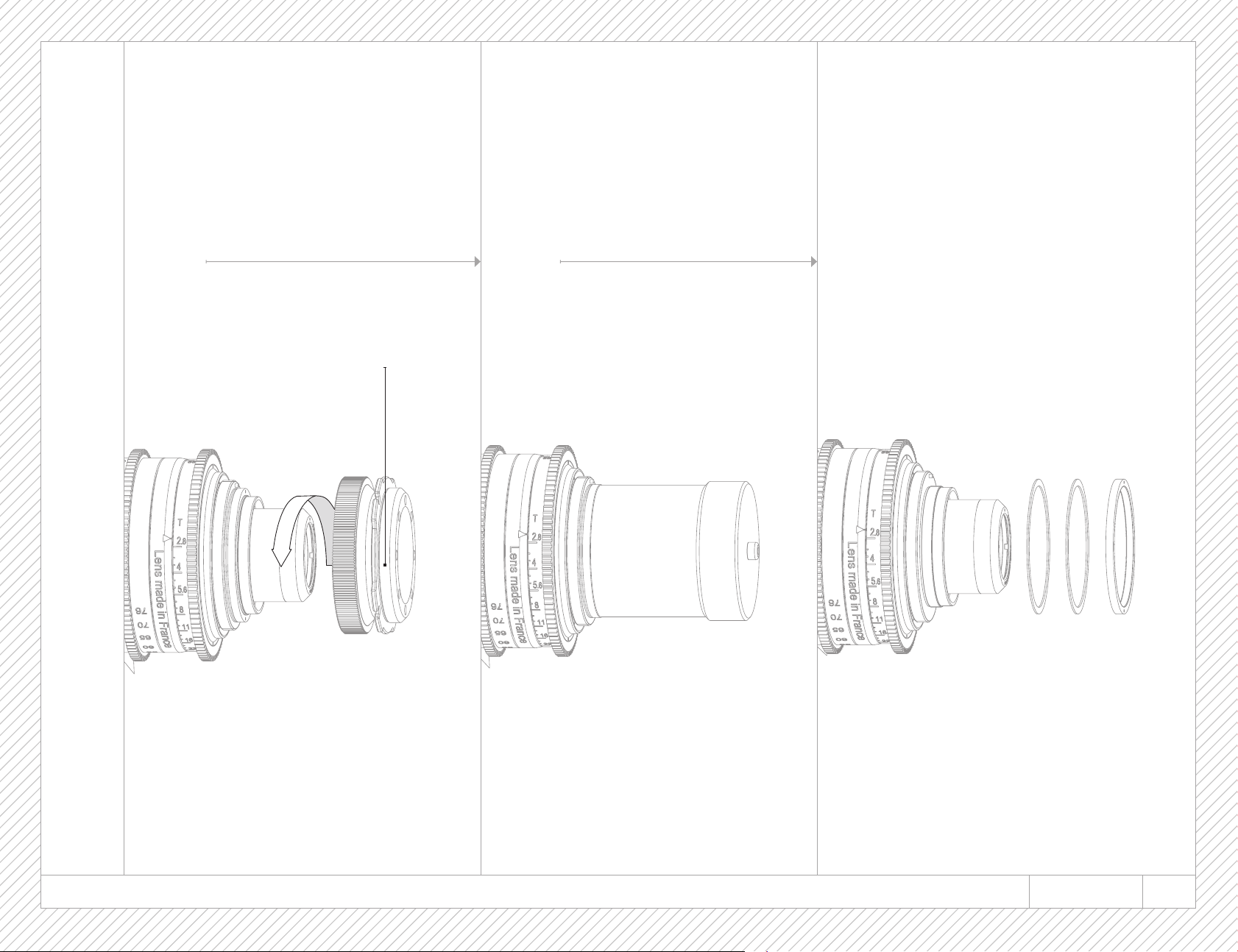
Picture 3
Figure 3
Picture 4
Figure 4
Picture 5
Figure 5
7
5 - BACK FOCUS AND TRACKING ADJUSTMENT I RÉGLAGE DU TIRAGE ET DU TRACKING OPTIMO STYLE 30-76 31
Page 32
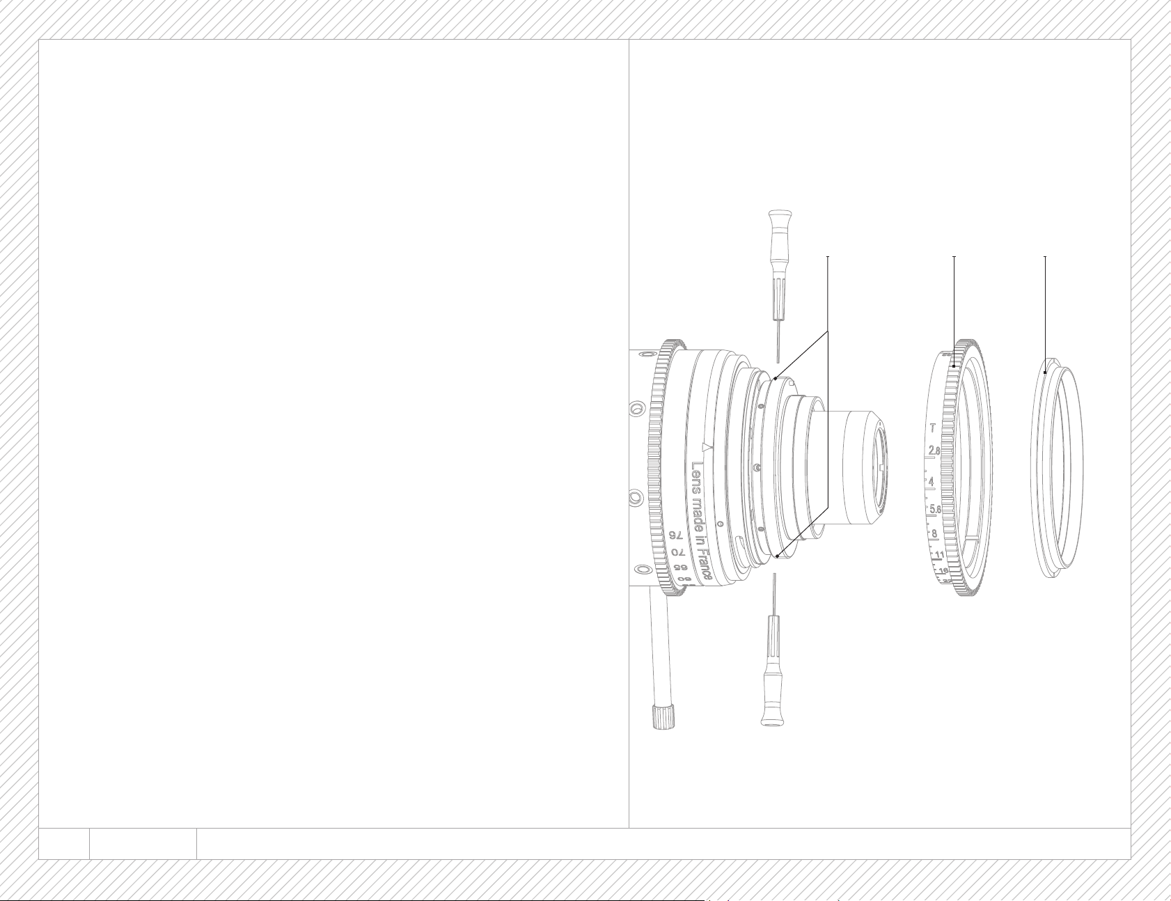
5.3 TRACKING ADJUSTMENT
- Remove the PL mount (7)
-Remove the retaining ring (12) with the spanner 197 659, then remove the iris ring
(11) (Picture 6)
- Reinstall the PL mount (7)
- Put the lens on a projector with a PL mount interface
- Put the projector at approximately 1.8 m (6ft) from the screen
- At long focal length, put a cross on the screen at the center of the image
- Put the lens at wide angle
- Measure the tracking T between the mark and the center of the image at wide angle
- If necessary, (according to specification on picture 7) adjust the tracking by moving
the neutral mount with the 4 screws (13) with a 0.9 mm Hex screw driver (Picture 6)
- Repeat the measurement to check the tracking adjustment
- Remove the PL mount (8)
- Reinstall the iris ring (11) and the retaining ring (12) with the spanner 197 659
- Reinstall the PL mount (7)
- Check if the tracking is still correct
5.3 RÉGLAGE DU TRACKING
Picture 6
Figure 6
121113
- Retirer la monture PL (7)
- Retirer l’écrou d’iris (12) avec la clé 197 659
- Retirer la bague d’iris gravée (12) (Figure 6)
- Remonter la monture PL (8)
- Monter un vérificateur PL sur l’objectif et monter l’ensemble sur un projecteur
- Se positionner à une distance d’environ 1.8 m de l’écran
- En longue focale, faire une marque au centre de l’image
- Placer l’objectif en courte focale
- Mesurer le tracking T entre la marque et le centre de l’image en courte focale
- Si nécessaire (selon spécification de la figure 7), reprendre le tracking par les 4 vis
(14) (figure 6) pour le ramener dans la spécification avec 2 clés six pans de 0.9 mm
- Répéter la mesure pour vérifier le réglage de tracking
- Retirer la monture PL (8)
- Remonter la bague d’iris gravée (12) et l’écrou d’iris (13) avec la clé 197 659
- Remonter la monture PL (8)
- Vérifier si le tracking est correct
32 OPTIMO STYLE 30-76 5 - BACK FOCUS AND TRACKING ADJUSTMENT I RÉGLAGE DU TIRAGE ET DU TRACKING
Page 33
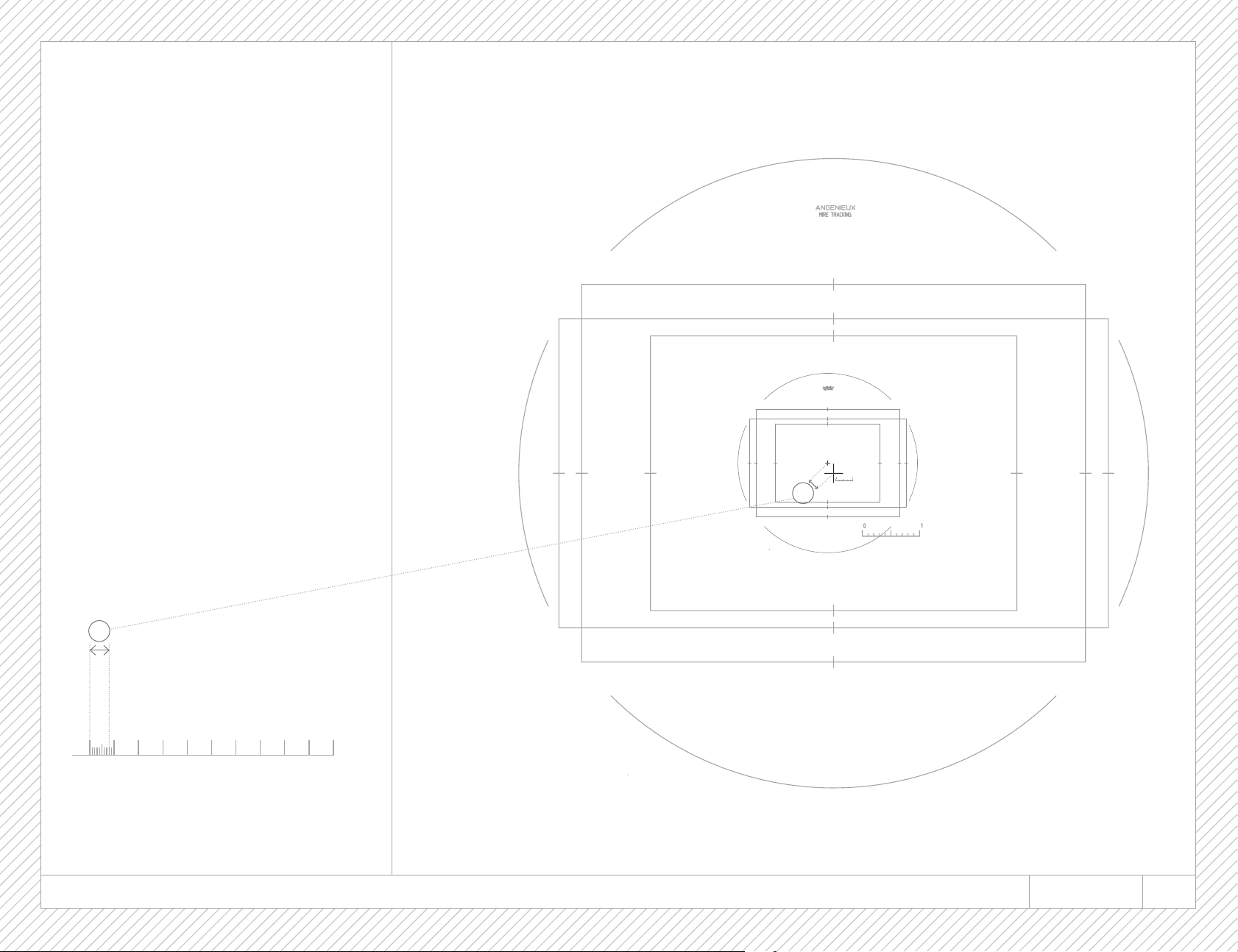
Picture 7
Figure 7
T
T
Specification 0,08 mm
1 mm
0 1
1 mm scale, short focal length
échelle de 1 mm, longueur focale minimale
2 3 4 5 6 7 8 9 10
5 - BACK FOCUS AND TRACKING ADJUSTMENT I RÉGLAGE DU TIRAGE ET DU TRACKING OPTIMO STYLE 30-76 33
Page 34

LENS VISUAL INSPECTION /
CONTRÔLE VISUEL D’ASPECT DE LENTILLE
Page 35

PANAVISION MOUNT
MONTURE PANAVISION
35
Page 36
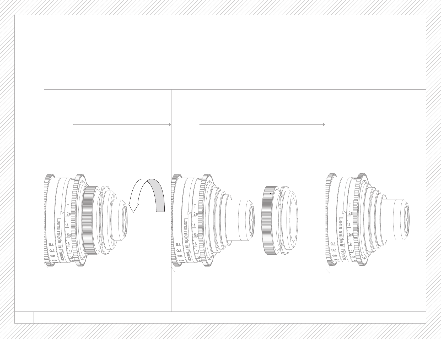
- Remove the PL mount (7) (picture 8 and 9)
- Install the Panavision mount (9) (picture 11 and 12)
- Check if the flange / back-focus adjustment is still correct. Readjust it if necessary.
- Check if the tracking is still correct. Readjust if necessary.
Picture 8
Figure 8
Picture 9
Figure 9
Picture 10
Figure 10
7
36 OPTIMO STYLE 30-76 6 - PANAVISION MOUNT I MONTURE PANAVISION
Page 37
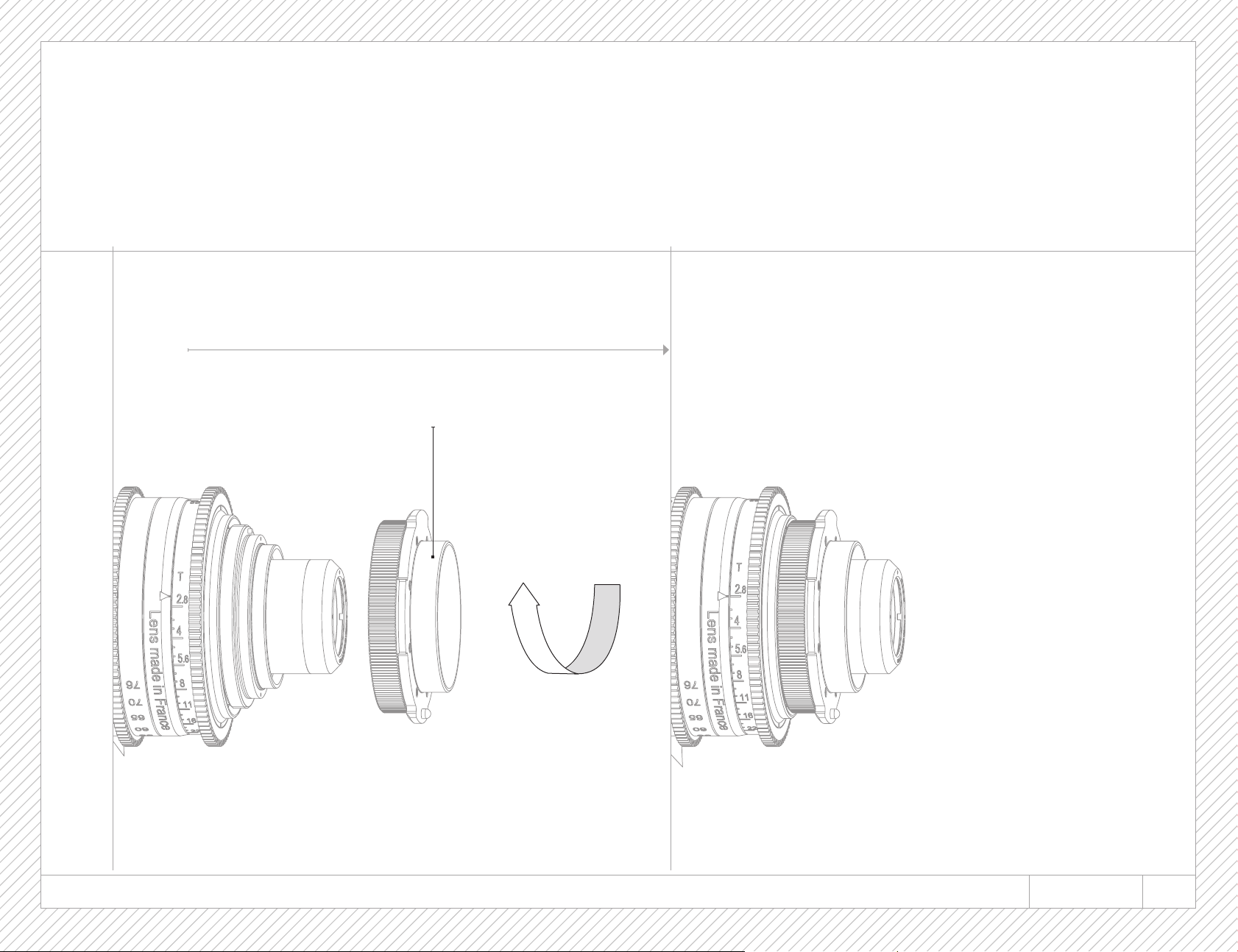
- Retirer la monture PL (7) (Figures 8 et 9)
- Monter la monture Panavision (9) (Figure 11 et 12)
- Vérifier si le tirage est correct. Le réajuster si nécessaire.
- Vérifier si le tracking est correct. Le réajuster si nécessaire.
Picture 11
Figure 11
Picture 12
Figure 12
9
6 - PANAVISION MOUNT I MONTURE PANAVISION OPTIMO STYLE 30-76 37
Page 38

MECHANICAL CONCEPTION /
CONCEPTION MECANIQUE
Page 39

OUTLINE DRAWING
PLAN D’ENCOMBREMENT
39
Page 40
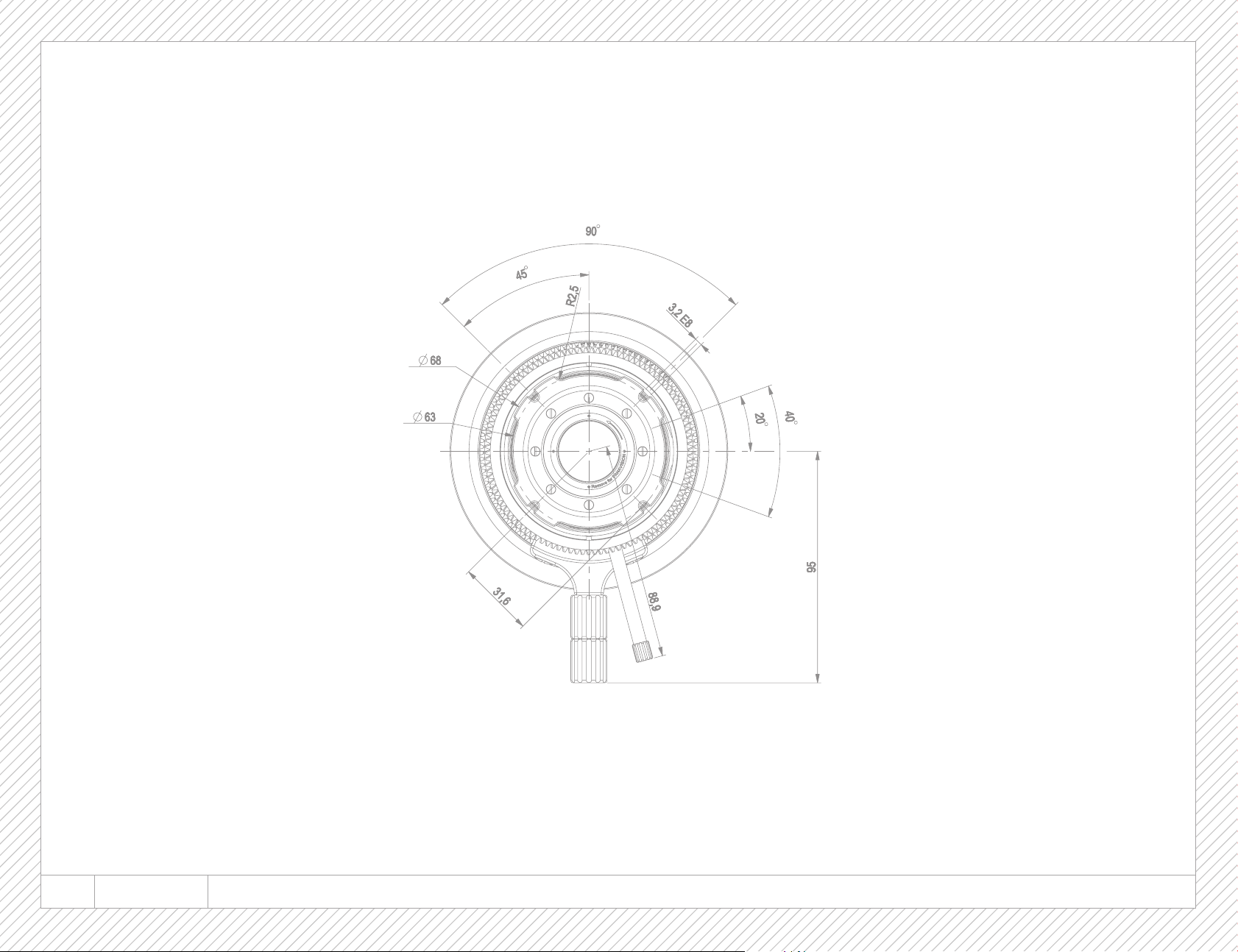
40 OPTIMO STYLE 30-76 7 - OUTLINE DRAWING I PLAN D’ENCOMBREMENT
Page 41
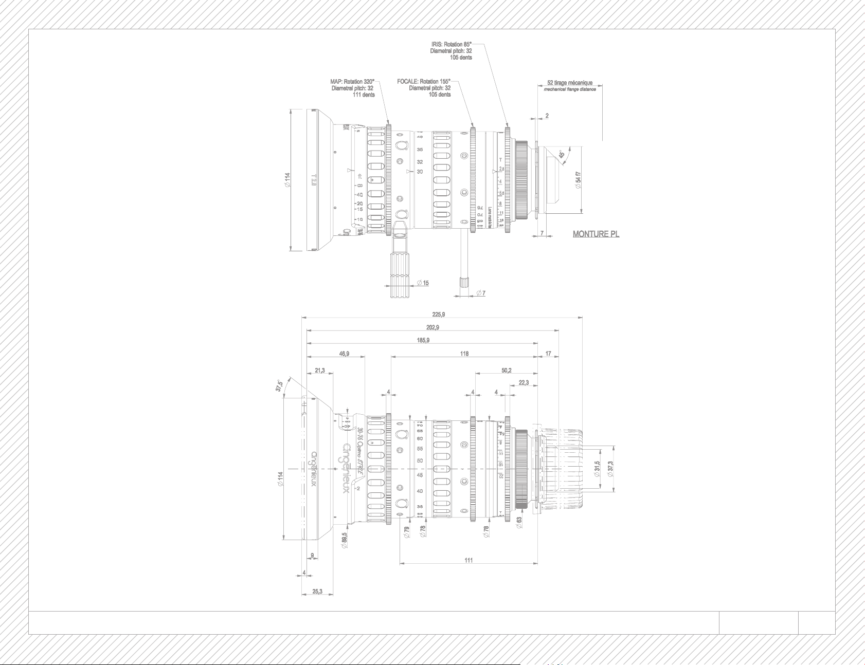
7 - OUTLINE DRAWING I PLAN D’ENCOMBREMENT OPTIMO STYLE 30-76 41
Page 42
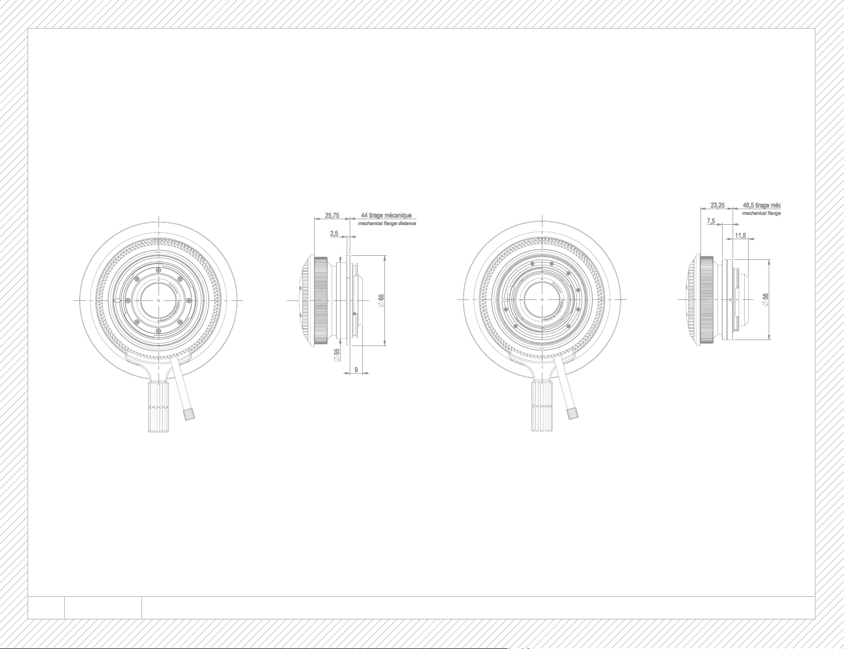
CANON NIKON
42 OPTIMO STYLE 30-76 7 - OUTLINE DRAWING I PLAN D’ENCOMBREMENT
Page 43
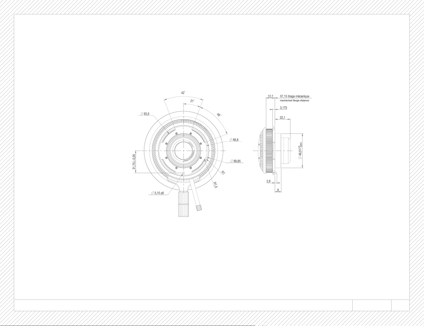
PANAVISION
7 - OUTLINE DRAWING I PLAN D’ENCOMBREMENT OPTIMO STYLE 30-76 43
Page 44

Thales Angenieux USA
40G Commerce Way
Totowa NJ 07512 - USA
Phone: 1 973 812 3858
Fax: 1 973 812 9049
angenieux@tccus.com
Thales Angenieux Headquarters
Boulevard Ravel de Malval
42570 Saint-Héand - FRANCE
Phone: +33 (0)4 77 90 78 00
Fax: +33 (0)4 77 90 78 03
[email protected]
Thales Angenieux in ASIA
10C Jalan Ampas #08-02
Ho Seng Lee Flatted Warehouse
Singapore 329513
Phone: +65 63 56 81 98
Fax: +65 62 50 60 85
[email protected]
www.angenieux.com
Création et direction artistique STUDIO QOOQ
 Loading...