

Page 1
CONTENTS
SPEED 05
1
The Angel is protected by the following Patents:
USA: 6 003 504, 6 138 656, 6 311 682, 6 748 938, 6 739 322,
6 615 814, D473 910, D484 926.
UK: 2 345 953, 2 342 710, 2 379 494, 2 384 292, 2 352 022
Plus other Patents Pending.
All rights will be strictly enforced.
• This Operators and Users Manual is in English.
• It contains important safety guidelines and Instructions.
• Should you be unsure at any stage, or unable to understand
the contents within this manual you must seek expert advice.
• Le mode d’emploi est en Anglais.
• Il contient des instructions et mesures de sécurité importantes.
• En cas de doute, ou s’il vous est impossible de comprendre
le contenu du monde d’emploi, demandez conseil à un expert.
WARNINGS
Important Safety Instructions & Guidelines 2
OPERATING INSTRUCTIONS
Replacing the PP3 9v Battery 3
Switching On Your ANGEL 3
Switching the ANGEL On/Off 3
Switching Angel Eyes On/Off 4
Propellant Air/Nitrogen Supply 4
Macro Line Hose/Connector attachment 4
Opto Board 5
Macro Line Hose removal and re-attachment
Loaders (Hoppers) 5
Soft Nose Bolt Removal & Rotor Breech
Velocity Adjustment
Twist Lock Feed Collar
Volumizer Accessories
6
6
6
5
5
LED MENUS
Internal Electronic Menus 7
Factory Default Settings 7
Dwell 7
Trigger Offset 7
MROF 8
Loader 8
Battery 8
Angel Eyes Service, Removal & Replacement 13
LPR Adjustment 14
LPR Assembly Removal 15
LPR Main Seal Replacement 1
Exhaust Guide Removal 16
Exhaust Valve Stem Removal 16
Ram Stroke Adjustment 17
Ram Removal
Ram Servicing
Vernier Trigger Adjustments 18
Vernier Trigger Wheel Removal 19
Wiring Connections 20
17
17
APPENDIX
Fault Finding Table 21
Useful Conversions 21
Terms of Warranty - EEC/R.O.W Exc USA/CAN
WDP Ltd. Express Warranty USA/CAN Only 23
Updates 24
Your Personal Details
22
24
5
• Este manual de (operarios y) usarios està en Inglés.
• Contiene importantes normas de seguridad e instrucciones.
• Si no esta seguro de algún punto o no entiende los contenidos
de este manual debe conultar con un experto.
• Diese Bedienungs- und Benutzeranleitung ist in Englisch.
• Sie enthält wichtige Sicherheitsrichtlinien und -bestimmungen.
• Sollten Sie sich in irgendeiner Weise unsicher sein, oder den Inhalt dieses
Heftes nicht verstehen, lassen Sie siche bitte von einem Experten beraten.
© 2004 WDP LTD.
MAINTENANCE
General Care and Cleaning 9
General Assembly - Right Hand View 9
General Assembly - Left Hand View 10
Sub Assemblies 10
Cutaway – Right Hand View 11
Cutaway – Left Hand View 11
Mini-Regulator Service 12
Anti-Double Ball Detent Service 12
Page 2

2
SPEED 05
Warnings: Important Safety Instructions & GuidelinesWARNINGS
WARNING
AD H ERE S TRI C T LY TO T HESE AND A LL O T HER S AFE T Y IN S TRUC T IONS AND G UID E L INE S
WARNINGS FOR SAFE ANGEL HANDLING
· The ANGEL is not a toy.
· Careless or improper use, including failure to follow instructions and warnings
within this Operator Manual and attached to the ANGEL could cause death or
serious injury.
· Do not remove or deface any warnings attached to the ANGEL.
· Paintball industry standard eye/face/ear and head protection designed
specifi cally to stop paintballs and meeting ASTM standard F1776 (USA) or CE
standard (Europe) must be worn by user and any person within range.
· Must be at least 18 years of age to purchase the ANGEL.
· Persons under 18 years of age must have adult supervision when using or
handling the ANGEL.
· Observe all local and national laws, regulations and guidelines.
· Use only on professional paintball fi elds where codes of safety are strictly
enforced.
· Use compressed air/nitrogen gas only. Do not use CO2.
· Do not exceed 850 psi (58 bar) input pressure.
· Always follow instructions, warnings and guidelines given with any fi rst stage
regulator you use with the ANGEL.
· Use 0.68 calibre paintballs only.
· Keep the ANGEL switched off until ready to shoot.
· Treat every marker as if it is loaded.
· Never point the ANGEL at anything you do not intend to shoot.
· Do not shoot at persons at close range.
· Do not shoot at fragile objects such as windows.
· Always measure your markers velocity before playing paintball, using a suitable
chronograph.
· Never shoot at velocities in excess of 300 feet (91.44 meters) per second, or at
velocities greater than local or national laws allow.
· Do not fi re the ANGEL with the breech open or without the bolt in the breech, as
high pressure gas will be emitted.
· Do not fi re the ANGEL with the pull knob in the unlocked position.
· Never look into the barrel or breech area of the ANGEL whilst the marker is
switched on and able to fi re.
· Never put your fi nger or any foreign objects into the paintball feed tube of the
ANGEL
· Never allow pressurised gas to come into contact with any part of your body.
· Always switch off the ANGEL when not in use.
· Always fi t a barrel blocking device to your ANGEL when not in use on the fi eld
of play.
· Always remove all paintballs from the ANGEL when not in use on the fi eld of
play.
· Always remove the fi rst stage regulator and relieve all residual gas pressure
from the ANGEL before disassembly.
· The ANGEL can hold a small residual charge of gas, typically 2 shots, with the
fi rst stage regulator removed. Always discharge the marker in a safe direction
to relieve this residual gas pressure.
· Always remove fi rst stage regulator and all residual gas pressure from the
ANGEL for transport and storage.
· Always follow warnings and guidelines given with your fi rst stage regulator for
safe transport and storage.
· Always store the ANGEL in a secure place.
· THIS OPERATOR MANUAL MUST ALWAYS ACCOMPANY THE PRODUCT IN THE
EVENT OF RESALE OR NEW OWNERSHIP.
· SHOULD YOU BE UNSURE AT ANY STAGE YOU MUST SEEK EXPERT ADVICE.
© 2004 WDP LTD.
Page 3
OPERATIONReplacing the Battery/Switching Your ANGEL ON/OFF
SPEED 05
3
REPLACING THE 9
v (PP3) Battery
OFF
2
3
2
1
1
2
ADHERE STRICTLY TO THESE
WARNING
· Ensure a barrel blocking device is fi tted to the ANGEL.
· Ensure the hopper is removed from the ANGEL.
· Ensure that there are no paintballs in the ANGEL.
· Ensure the ANGEL is switched off via the isolating switch at the rear of the
marker prior to fi tting your fi rst stage regulator.
· Paintball industry standard eye/face/ear and head protection designed
specifi cally to stop paintballs and meeting ASTM standard F1776 (USA) or CE
standard (Europe) must be worn by user and any person within range.
· Always follow instructions, warnings and guidelines given with any fi rst stage
regulator you use with the ANGEL.
· Use compressed air/nitrogen gas only DO NOT USE CO2.
· Only use a paintball regulator that has been designed for air or nitrogen gas.
· Do not exceed 850 psi (58bar) input pressure to the ANGEL.
· Take suitable precautions when using sharp cutting instruments.
· The Macro Line hose must be cut back cleanly and square prior to attachment
or re-attachment to ensure secure fi tment.
· SHOULD YOU BE UNSURE AT ANY STAGE YOU MUST SEEK EXPERT ADVICE.
AND ALL OTHER SAFETY
INSTRUCTIONS AND GUIDELINES
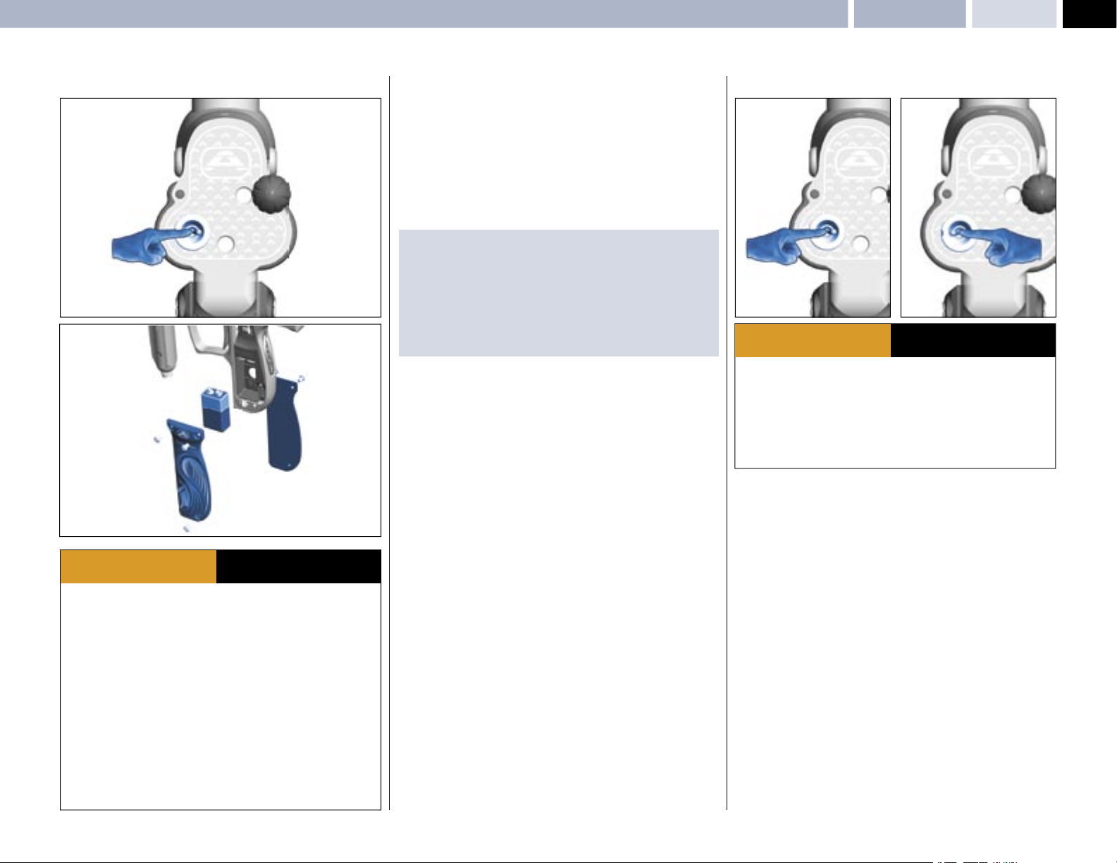
• Ensure the isolator switch is in the OFF position.
• Remove the left & right hand grip cheeks
2 using a suitable 2.5 mm Allen Key.
• Carefully lift the battery
• Observe the battery polarity as marked on the battery housing and the battery.
• Insert a good quality fresh battery
IMPORTANT NOTES:
• We recommend the use of good quality 9v (PP3) batteries such as those
produced by Duracell ™.
• Batteries that leak may cause damage to the electronics.
• Re-chargable batteries may be used but must be charged out of the Angel
and follow the instructions supplied.
• The use of inferior batteries may affect the performance of the Angel.
• Dispose of used batteries responsibly.
3 from its housing if a battery is already present.
1 by removing the 6 M4 screws
3.
SWITCHING ON YOUR ANGEL
ONOFF
ADHERE STRICTLY TO THESE
WARNING
· Ensure a barrel blocking device is fi tted to the ANGEL.
· Ensure the hopper is removed from the ANGEL.
· Ensure that there are no paintballs in the ANGEL.
· Ensure the ANGEL is switched off via the isolating switch at the rear of the
marker prior to fi tting your fi rst stage regulator.
· Paintball industry standard eye/face/ear and head protection designed
specifi cally to stop paintballs and meeting ASTM standard F1776 (USA) or CE
standard (Europe) must be worn by user and any person within range.
• We recommend the isolating switch be placed in the OFF position when the
ANGEL is in storage, transit or not in use.
• Ensure that good quality battery is used, we recommend the use
of Duracell™ batteries.
• Switch the isolator switch to the ON position.
• The LED display will show the battery status for a short period of time.
• The more LED’s displayed indicates the more battery life present.
(See Battery Page 8)
AND ALL OTHER SAFETY
INSTRUCTIONS AND GUIDELINES
© 2004 WDP LTD.
Page 4
4
SPEED 05
OPERATION Switching ANGEL Eyes On/Off – Propellant Air/Nitrogen Supply – Macro Line Hose
SWITCHING ANGEL EYES ON/OFF
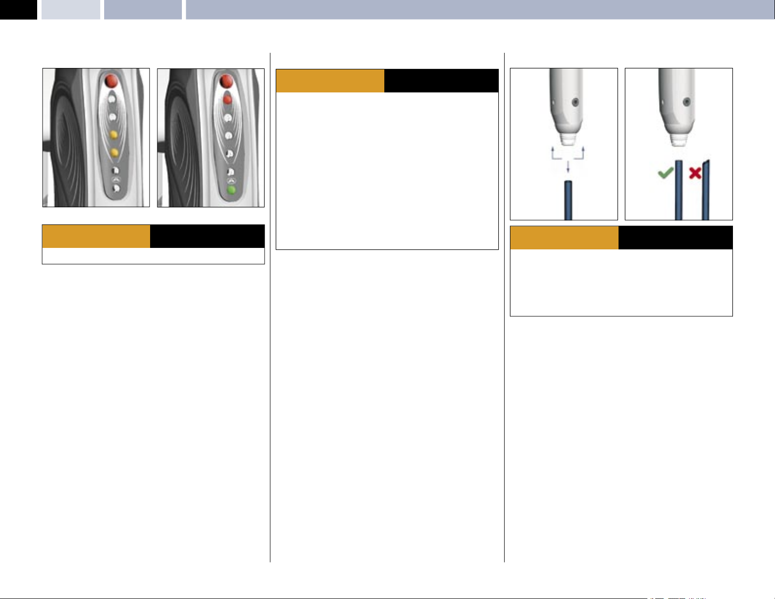
EYES ON: NO PAINTBALL PRESENT
WARNING
· THE ANGEL IS LIVE AND CAPABLE OF DISCHARGING.
• Ensure the ANGEL is switched ON. See SWITCHING ON YOUR
ANGEL- Page 3.
• As default the Angel Eyes will always be ON whenever the ANGEL is switched
ON.
• The Angel Eyes can only be switched OFF by pulling and holding the trigger in
for 2 seconds. The ANGEL will fi re to confi rm the eyes have been switched OFF.
• To switch the Angel Eyes back ON you must switch the ANGEL OFF and then
ON via the isolator switch.
• If the Angel Eyes are functioning correctly the LED display will fl ash each time
a paintball is sensed. Therefore, to test if the eyes are functioning correctly,
simply drop a ball into the breech.
TOP LED INDICATOR STATUS ON THE REAR OF THE FRAME
• RED CONSTANTLY ON = ANGEL EYES ON.
• GREEN CONSTANTLY ON = ANGEL EYES OFF.
EYES ON: PAINTBALL PRESENT
ADHERE STRICTLY TO THESE
AND ALL OTHER SAFETY
INSTRUCTIONS AND GUIDELINES
PROPELLANT AIR / NITROGEN SUPPLY
ADHERE STRICTLY TO THESE
WARNING
· Ensure a barrel blocking device is fi tted to the ANGEL.
· Ensure the hopper is removed from the ANGEL.
· Ensure that there are no paintballs in the ANGEL.
· Ensure the ANGEL is switched off via the isolating switch at the rear of the
marker prior to fi tting your fi rst stage regulator.
· Paintball industry standard eye/face/ear and head protection designed
specifi cally to stop paintballs and meeting ASTM standard F1776 (USA) or CE
standard (Europe) must be worn by user and any person within range.
· Always follow instructions, warnings and guidelines given with any fi rst stage
regulator you use with the ANGEL.
· Use compressed air/nitrogen gas only DO NOT USE CO2.
· Only use a fi rst stage paintball regulator that has been designed for air or
nitrogen gas.
· Do not exceed 850 psi (58bar) input pressure to the ANGEL.
· Take suitable precautions when using sharp cutting instruments.
· The Macro Line hose must be cut back cleanly and square prior to attachment
or re-attachment to ensure secure fi tment.
The ANGEL is designed to operate on air/nitrogen gas. This needs to be supplied
to the ANGEL at an ideal regulated pressure of 400 psi (27.5 BAR) using a
suitable fi rst stage paintball regulator, such as the ANGEL A.I.R.
AND ALL OTHER SAFETY
INSTRUCTIONS AND GUIDELINES
MACRO LINE HOSE
1 1
3
2
ADHERE STRICTLY TO THESE
WARNING
· All gas pressure must be relieved from the ANGEL and second stage regulator
prior to the Macro Line hose removal.
· The ANGEL can hold a small residual charge of gas, typically 2 shots with the
fi rst stage regulator removed. Always discharge the marker in a safe direction to
relieve this residual gas pressure.
· The Macro Line hose must be cut back cleanly and square prior to
re-attachment to ensure secure fi tment.
MACRO LINE HOSE / CONNECTOR REPLACEMENT
• Connect the Macro Line connector to your second stage regulator outlet port
using a suitable wrench or spanner.
• If necessary shorten the Macro Line hose using a sharp knife to the required
length to suit your ANGEL and fi rst stage regulator set up.
• Push the free end of the hose fi rmly into the Macro Line connector attached to
the ANGEL second stage regulator.
REMOVAL & RE-ATTACHMENT
• The Macro Line hose may be removed from the Macro Line connectors to
facilitate maintenance.
• Pull back the collet 1 on the connector and keep the collet depressed.
• Pull the Macro Line hose 2 out of the connector fi rmly.
• Cut back the Macro Line hose cleanly and square
• Push the hose fi rmly into the Macro Line connector to re-attach.
AND ALL OTHER SAFETY
INSTRUCTIONS AND GUIDELINES
3.
© 2004 WDP LTD.
Page 5
OPERATIONOpto Board – Loaders – Soft Nose Bolt Removal & Rotor Breech
SPEED 05
5
OPTO BOARD
.
ADHERE STRICTLY TO THESE
WARNING
· Do not attempt to modify the OPTO™ board assembly in any way as this will
invalidate your warranty and could lead to safety concerns.
The ANGEL incorporates the OPTO™ board. This is the latest development
in trigger sensing function. It achieves unsurpassed advancements in trigger
repeatability and sensitivity, its non-mechanical touching switch results in faster,
shorter and lighter trigger strokes that give the user higher prolonged achievable
rates of fi re.
IMPORTANT NOTES:
· When accessing the Internal Tournament LED menus the OPTO™ board
should not be exposed to direct sunlight or strong external sources of light
without the grip cheek fi tted as this light will induce a safety feature, that will
prevent the ANGEL from fi ring whilst it remains exposed to the strong external
light.
· The OPTO™ board is a non-mechanical touching switch that is silent in its
operation and no audible click is present.
AND ALL OTHER SAFETY
INSTRUCTIONS AND GUIDELINES
LOADERS (HOPPERS)
The ANGEL has been designed to work with all existing loaders and intelligently
self adjusts its program to suit the loaders feed rates for the type of loader
selected from the Advanced Menu - see page 7, but there are some important
things to remember about loaders:
• The Angel Eyes system will shoot paint as fast as your loader is capable of
feeding in combination with trigger pulls.
• Some loaders, particularly those with a refl ective eye system DO NOT correctly
sense twin skin, marbleized or dark coloured paintballs, and as such, these
loaders are capable of breaking or cracking paintballs before they are even
loaded into the ANGEL.
• All loaders should only be used with fresh batteries.
• It is also essential that the loader and its optical system is kept clean at all
times.
• Force fed loaders, due to the nature of their design are less tolerant of fragile
and poor quality paint, causing breaks in the loader, and feed stack before
they are loaded into the ANGEL.
• Some loaders are not capable of sustained feed rates and you will be able
to outshoot the loader, causing the Angel Eyes to wait for verifi cation of a
paintball before commencing the fi ring cycle.
• Poorly maintained or damaged loaders will impair the performance capability
of the ANGEL.
• To maximise the performance of the ANGEL, WDP recommends only using
reliable enhanced feed loaders.
(See also Loader Type Settings Page 8)
SOFT NOSE BOLT REMOVAL & ROTOR BREECH
ADHERE STRICTLY TO THESE
WARNING
· Do not fi re the ANGEL with the breech open or without the bolt in the breech,
as high pressure gas will be emitted.
· Do not fi re the ANGEL with the pull knob in the unlocked position.
BOLT REMOVAL & ROTOR BREECH
The bolt is manufactured from aluminium and plastic with the wear surfaces
being plastic, this is to ensure – due to its high operating speeds – it does not
seize within the body. Eventually this will show signs of wear dependent on
usage and its environment of use.
It is important that the bolt is kept clean and free of dirt or grit as this will cause
accelerated wear. We recommend that you clean your bolt after each day of play.
• Ensure the ANGEL isolator switch is in the OFF position or the ANGEL is in
SAFE mode.
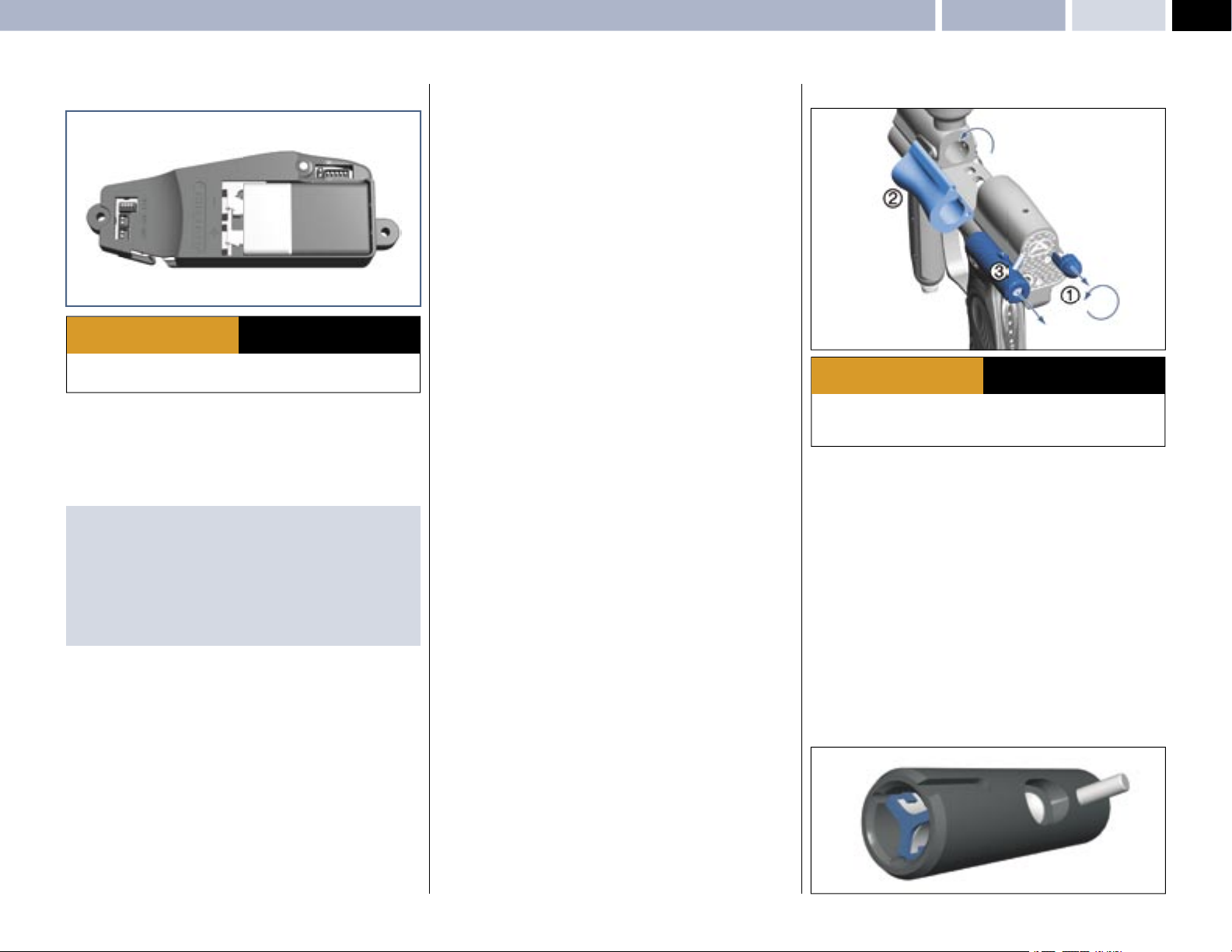
• Pull the Pull knob
unlocked position.
• Swing out the Rotor Breech block
will not open if the bolt is in the forward position. Ensure it is retracted by
either: momentarily gassing the ANGEL or pushing the bolt back with a
squeegee.
• Extract the bolt by pulling rearwards
• To replace the bolt follow the stages in reverse order.
1 and rotate 90 degrees so that the knob remains in the
AND ALL OTHER SAFETY
INSTRUCTIONS AND GUIDELINES
2 so that the bolt is exposed. The breech
3.
© 2004 WDP LTD.
Page 6
6
SPEED 05
Velocity Adjustment – Twist Lock Feed Collar – Volumizer AccessoriesOPERATION
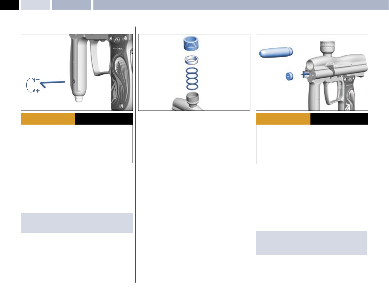
VELOCITY ADJUSTMENT (2nd Stage Regulator)
ADHERE STRICTLY TO THESE
WARNING
· THE ANGEL IS LIVE AND CAPABLE OF DISCHARGING
· Paintball industry standard eye/face/ear and head protection designed
specifi cally to stop paintballs and meeting ASTM standard F1776 (USA) or CE
standard (EU) must be worn by user and any person within range.
· Always measure your markers velocity before playing paintball, using a suitable
chronograph.
· Never shoot at velocities in excess of 300ft (91.44 meters) per second, or at
velocities greater than local or national laws allow.
DECREASING VELOCITY
The velocity adjusting screw is located on the lower portion of the front grip.
• To decrease the velocity, insert a 3.0mm A/F Allen key and rotate CLOCKWISE.
INCREASING VELOCITY
The velocity adjusting screw is located on the lower portion of the front grip.
• To increase the velocity, insert a 3.0mm A/F Allen key and rotate
ANTI-CLOCKWISE.
IMPORTANT NOTE:
· When reducing velocity, allow four shots for the complete system to be at the
new regulated pressure.
AND ALL OTHER SAFETY
INSTRUCTIONS AND GUIDELINES
.
TWIST LOCK COLLAR FEED
3
2
1
The Twist Lock Feed Collar is a dual feature that retains your loader securely to
the ANGEL.
TWIST LOCK COLLAR
• To secure your loader, fi rst ensure the Twist Lock collar is backed off by
rotating it counter-clockwise.
• The Twist Lock Collar feature has been supplied with two sizes of ‘O’ rings
1 to ensure that the full range of loader neck sizes are covered. If the loader
is diffi cult to insert when 3 has been backed off, follow the procedure to
replace the ‘O’ rings:
• Unscrew 3 by rotating counter clockwise.
• Extract spacer 2.
• Extract ‘O’ rings
• Re-assemble in reverse order.
• Insert the loader into the feed neck and rotate the Twist Lock collar clockwise
to secure the loader.
1 and replace with compatible size.
VOLUMIZER ACCESSORIES
3
1
WARNING
· Ensure a barrel blocking device is fi tted to the ANGEL.
· Ensure the hopper is removed from the ANGEL.
· Ensure that there are no paintballs in the ANGEL.
· Always remove the fi rst stage regulator and relieve all residual gas pressure
from the ANGEL before disassembly.
· The ANGEL can hold a small residual charge of gas, typically 2 shots, with the
fi rst stage regulator removed. Always discharge the marker in a safe direction to
relieve this residual gas pressure.
The ANGEL has been designed to accept volumizers that attach to the front
of the ANGEL. Attachment of volumizers will allow the working pressure of the
ANGEL to be reduced to suit specifi c performance requirements.
The volumizer supplied with your ANGEL will reduce the operating pressure to
aproximately 150 psi.
• Unscrew and remove the mini regulator.
• Remove the left end cap
• Ensure the valve spring, support bobbin
in place.
• Replace the left hand cap with the volumizer
IMPORTANT NOTES: For re-assembly of components
· Ensure the valve spring, support bobbin and exhaust valve stem remain in
place.
· Ensure the end cap is located correctly.
2
ADHERE STRICTLY TO THESE
AND ALL OTHER SAFETY
INSTRUCTIONS AND GUIDELINES
1 using suitable metric 4.0mm A/F Allen key.
2 and exhaust valve stem remain
3
© 2004 WDP LTD.
Page 7
LED MENUSInternal Electronic LED Menus: Trigger offset - Dwell - Loader (Hopper) Type - Battery Status - Factory Default
SPEED 05
7
3
1
1
2
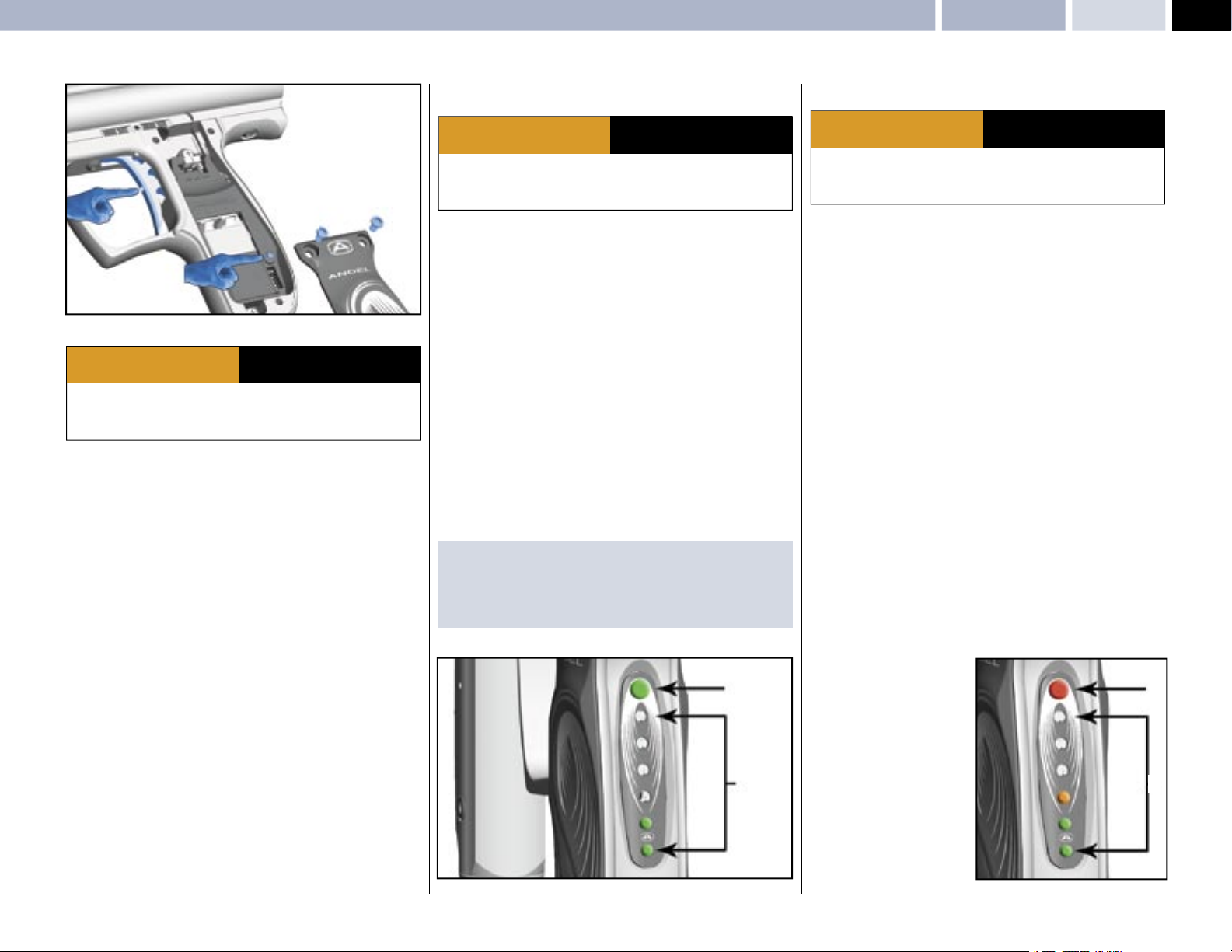
INTERNAL ELECTRONIC LED MENUS
ADHERE STRICTLY TO THESE
WARNING
· Ensure a barrel blocking device is fi tted to the ANGEL.
· Ensure the hopper is removed from the ANGEL.
· Ensure that there are no paintballs in the ANGEL.
The ANGEL has a number of features that can be adjusted to suit your individual
needs. These features that can change the performance of the gun are only
accessable via the internal menu. This is to ensure that they pass tournament
and fi eld operator requirements.
• The menus can only be accessed when the marker is switched ON.
• Remove left hand grip cover screws
• Follow the internal menu list diagrams for relevant settings.
• Any menu that has been accessed via the internal menu will disable the Angel
and prevent the Angel from fi ring as a safety feature. It is nessary to switch
the Angel OFF to store the settings once you have fi nished your adjustments.
Switching the Angel back ON enables the new settings to take effect and to
enable the Angel to be capable of fi ring.
AND ALL OTHER SAFETY
INSTRUCTIONS AND GUIDELINES
1 to expose the circuit board.
DWELL
ADHERE STRICTLY TO THESE
WARNING
· Ensure a barrel blocking device is fi tted to the ANGEL.
· Ensure the hopper is removed from the ANGEL.
· Ensure that there are no paintballs in the ANGEL.
Dwell controls the valve opening time. Longer Dwell uses more gas and
generates pressure variables. Shorter Dwell uses less gas and reduces noise,
but is less tolerant of poor quality paint. The range available is 7-12milliseconds.
• The menus can only be accessed when the ANGEL is ON.
• Remove left hand grip cover screws
• Switch the Angel ON.
• Ensure that you are not depressing the trigger.
• Press the internal menu button
fl ashes GREEN.
• Depress the trigger
the rear of the grip frame will indicate what level you have selected.
• Pull the trigger
by 1 millisecond).
• Any menu that has been accessed via the internal menu will disable the Angel
and prevent the Angel from fi ring as a safety feature. It is nessary to switch
the Angel OFF to store the settings once you have fi nished your adjustments.
Switching the Angel back ON enables the new settings to take effect and to
enable the Angel to be capable of fi ring
IMPORTANT NOTE:
Adjustment is only recommended if you wish to fi ne tune your marker to
specifi c accessories.
3 for each level of adjustment required, the LED’s 5 on
3 to adjust the settings (each trigger pull will adjust the dwell
2 to scroll the menu until the TOP LED 4
AND ALL OTHER SAFETY
INSTRUCTIONS AND GUIDELINES
1 to expose the circuit board.
TRIGGER OFFSET
ADHERE STRICTLY TO THESE
WARNING
· Ensure a barrel blocking device is fi tted to the ANGEL.
· Ensure the hopper is removed from the ANGEL.
· Ensure that there are no paintballs in the ANGEL.
This allows the user to set the trigger snubber and can be used to ensure
that trigger bounce is reduced on triggers that have been set. It should be
used to eliminate trigger bounce and not used to induce trigger bounce.
The level of snubbing required will be dependent on the users setting of the
mechanical adjustments of the trigger. The snubber will be automatically set
to the highest level of protection on all modes as factory default. It is the users
responsibility to ensure that the settinf selected does not cause accidental
discharge
There are fi ve levels of adjustment + DEMO mode. A single Green LED on the
bar graph display is the minimum amount of trigger offset and increasing the
settings (more LEDs illuminate) reduces the damping. The sixth LED indicates
that you are in DEMO mode.
• The menus can only be accessed when the ANGEL is ON.
• Remove left hand grip cover screws
• Switch the Angel ON.
• Ensure that you are not depressing the trigger.
• Press the internal menu button
fl ashes RED.
• Depress the trigger
the rear of the grip frame will indicate what level you have selected
• The bottom LED
the least amount of trigger switch bounce. The top LED indicates that you are
in DEMO mode. This is a dry fi ring mode for fi ring the Angel with the display
on and is designed to demonstrate the rate of fi re achievable. It should only
be used for demonstration purposes, as the Angel Eyes feature is reverse
functioned so that it cannot fi re paintballs. Should a paintball be detected it
will prevent the ANGEL from fi ring.
3 for each level of adjustment required the LED’s 5 on
5 indicates the maximum level of trigger snubbing giving
2 to scroll the menu until the TOP LED 4
AND ALL OTHER SAFETY
INSTRUCTIONS AND GUIDELINES
1 to expose the circuit board.
FACTORY DEFAULT SETTING
• Press and hold the INTERNAL button 2 for 2 seconds then release and the
factory defaults will be loaded.
© 2004 WDP LTD.
4
5
Any menu that has been accessed
via the internal menu will disable
the Angel and prevent the Angel
from fi ring as a safety feature. It is
necessary to switch the Angel OFF
to store the settings once you have
fi nished your adjustments.
Switching the Angel back ON
enables the new settings to take
effect and to enable the Angel to
be capable of fi ring.
4
5
Page 8
8
SPEED 05
LED MENUS INTERNAL Electronic LED Menus: Trigger Offset - Dwell - Loader (Hopper) Type - Battery Status - Factory default
MROF
ADHERE STRICTLY TO THESE
WARNING
· Ensure a barrel blocking device is fi tted to the ANGEL.
· Ensure the hopper is removed from the ANGEL.
· Ensure that there are no paintballs in the ANGEL.
MAXIMUM RATE OF FIRE LIMIT WITH ANGEL EYES OFF -
This is fi xed at a MROF value of 18 BPS and non adjustable.
MAXIMUM RATE OF FIRE LIMIT WITH ANGELS EYES ON -
There is no fi xed limit and is capable of fi ring as fast as the loader is capable of
feeding paintballs and your fi nger activating the trigger.
AND ALL OTHER SAFETY
INSTRUCTIONS AND GUIDELINES
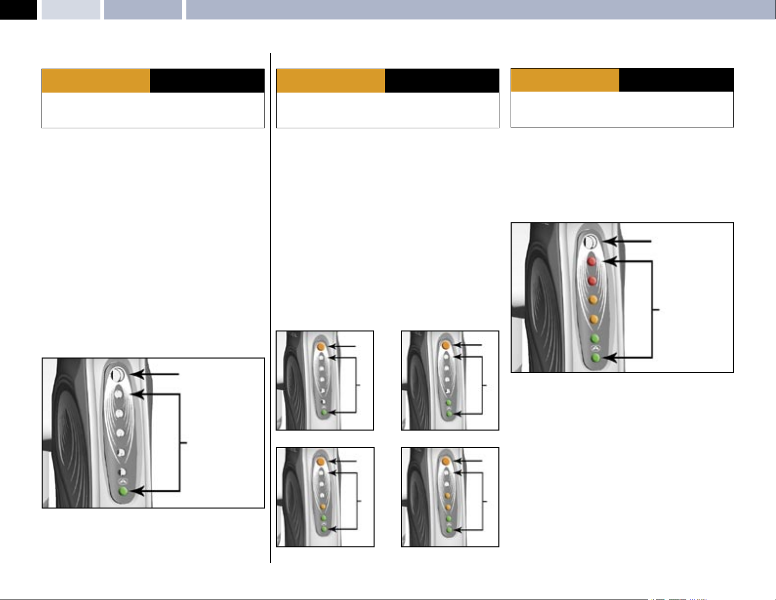
SOFTWARE VERSION
This allows you to check the Software version programmed into the Angel
Speed.
• The menus can only be accessed when the ANGEL is ON.
• Remove left hand grip cover screws
• Switch the Angel ON.
• Ensure that you are not depressing the trigger.
• Press the internal menu button
NOT Illuminated.
• Depress the trigger for each level of adjustment required the LED’s on the rear
of the grip frame will indicate what level you have selected
• The LED displayed indicates the software version.
1 to expose the circuit board.
2 to scroll the menu until the TOP LED 4 is
LOADER (HOPPER) TYPE
ADHERE STRICTLY TO THESE
WARNING
· Ensure a barrel blocking device is fi tted to the ANGEL.
· Ensure the hopper is removed from the ANGEL.
· Ensure that there are no paintballs in the ANGEL.
This allows you to select the correct Angel Eyes settings for the type of loader
that you are using. There are 4 types of loader setting that you may select Once
you have selected the correct setting the Angel Eyes program will intelligently
adjust itself to the variable speeds of your loader. The MROF limits you have set
will only be active whilst Angel Eyes are OFF.
• The menus can only be accessed when the ANGEL is ON.
• Remove left hand grip cover screws
• Switch the Angel ON.
• Ensure that you are not depressing the trigger.
• Press the internal menu button
ORANGE.
• Depress the trigger
the rear of the grip frame will indicate what level you have selected.
• Pull the trigger to select one of the 4 settings of the loader menu. An LED will
illuminate on the LED bar graph to indicate which setting has been selected
for the loader type required .
• The Angel is incapable of fi ring whilst you are using the internal menu and
must be switch OFF then ON to save the settings and enable the Angel to fi re.
3 for each level of adjustment required the LED’s 5 on
2 to scroll the menu until the TOP LED fl ashes
4
AND ALL OTHER SAFETY
INSTRUCTIONS AND GUIDELINES
1 to expose the circuit board.
4
BATTERY
ADHERE STRICTLY TO THESE
WARNING
· Ensure a barrel blocking device is fi tted to the ANGEL.
· Ensure the hopper is removed from the ANGEL.
· Ensure that there are no paintballs in the ANGEL.
The battery status can be checked by the LED display bar graph whenever the
ANGEL is fi rst switched ON. The LED bar graph will illuminate to indicate power
remaining.
• Switch the ANGEL OFF only if the ANGEL was switched ON.
• Switch the ANGEL ON.
• The LED
• The LED
5 display will show battery status for a short time.
5 display will now display a single Green LED.
AND ALL OTHER SAFETY
INSTRUCTIONS AND GUIDELINES
4
5
4
5
LOADER - 9v Agitator Type
5
4
5
5
LOADER - 12-18v Agitator Type
5
5
LOADER - Fast Force-Fed TypeLOADER - Force-Fed Type
NEW BATTERY = RED WEAK BATTERY = GREEN
© 2004 WDP LTD.
Page 9
GENERAL CARE AND CLEANING
ADHERE STRICTLY TO THESE
WARNING
· Ensure a barrel blocking device is fi tted to the ANGEL.
· Ensure the hopper is removed from the ANGEL.
· Ensure that there are no paintballs in the ANGEL.
· Always remove the fi rst stage regulator and relieve all residual gas pressure
from the ANGEL before disassembly.
· The ANGEL can hold a small residual charge of gas, typically 2 shots, with the
fi rst stage regulator removed. Always discharge the marker in a safe direction to
relieve this residual gas pressure.
The ANGEL should only be cleaned externally using a synthetic oil moistened
cloth only. Under no circumstances should you use hydrocarbon based oils, as
these will cause irrevocable damage to the internal seals, e.g.: WD40, Vaseline,
Duck Oil, Engine oil, Plus Gas, 3in1. The suitable oil is Love Juice Oil.
The ram shaft and internal parts that are accessible during disassembly and
re-assembly should be lubricated with Love Juice Extreme Grease.
The frequency of lubrication should be every event or at least 8000 shots for oil
lubrication and 20,000 shots for grease lubrication. The ANGEL should never be
immersed into water otherwise damage may occur to the electronics.
The electronics are moisture/damp proof to IP65. Ensure correct tools are used.
AND ALL OTHER SAFETY
INSTRUCTIONS AND GUIDELINES
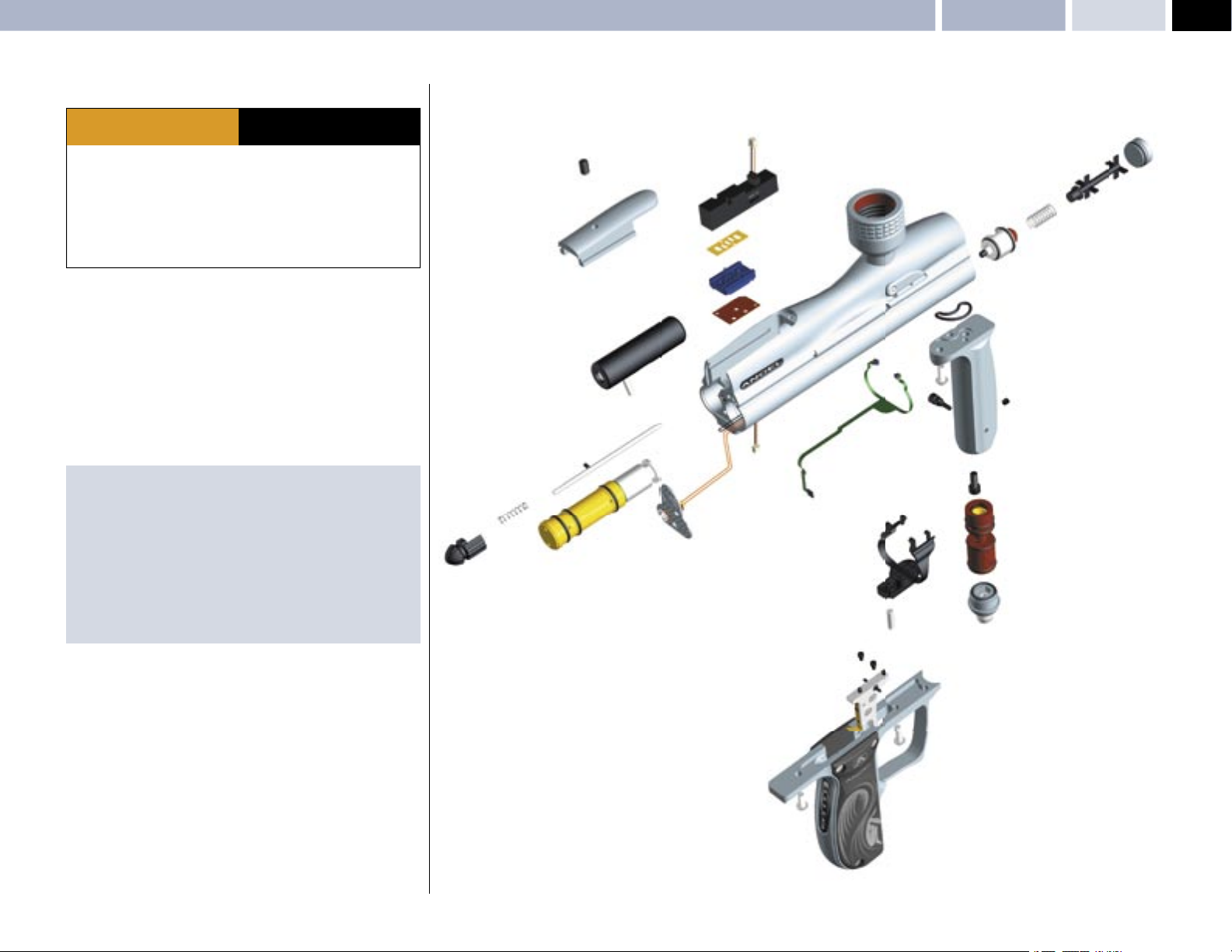
General Care & Cleaning – General Assembly: Right Hand View MAINTENANCE
SOLENOID
COVER PLATE
ANGEL EYES
PULL PIN
EXHAUST VALVE
EXHAUST VALVE GUIDE
EXHAUST VALVE STEM
REGULATOR FOREGRIP
SPEED 05
END PLUG
9
IMPORTANT NOTES: For General Maintenance
· No solvents or abrasive cleaning products should be used. All external and
internal accessible moving parts should be lubricated using light synthetic
oil only.
· All threads are metric except gun accessory mountings onto the grip frame,
which is industry standard 10/32 UNF at centres 0.75 inches. The screw
thread length must not exceed 0.375 inches (10mm) into the bottom of the
frame otherwise damage will occur to the electronics. We recommend that
you remove the left-hand cheek cover and ensure the screws do not project
into the circuit board cavity when fi tting.
© 2004 WDP LTD.
PULL KNOB
RAM
BACK PLATE
MINI - REGULATOR
ANGEL EYES COVER
REGULATOR END CAP
TRIGGER
GRIP FRAME
Page 10
10
SPEED 05
MAINTENENCE General Assembly: Left Hand View – Sub Assemblies
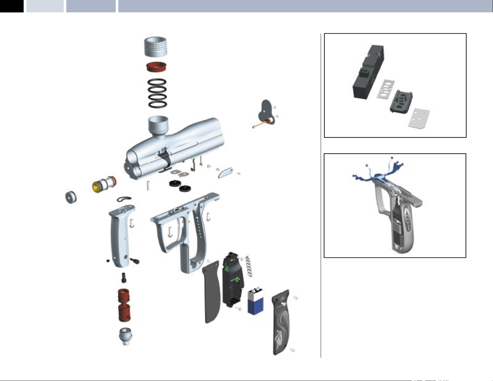
TWIST LOCK GATED FEED
BACK PLATE
SOLENOID ASSEMBLY
ANTI DOUBLE BALL ASSEMBLY
LPR
END PLUG
REGULATOR FOREGRIP
MINI - REGULATOR
REGULATOR END CAP
VERNIER WHEELS
GRIP FRAME
PCB OPTO BOARD
LED INDICATORS
BATTERY
ANGEL EYES SENSOR
© 2004 WDP LTD.
Page 11
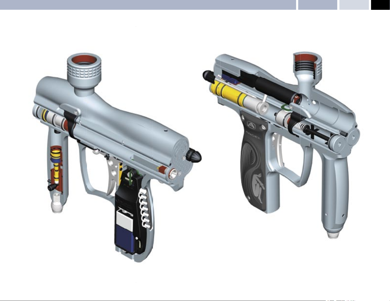
Cut Away Views: Right Hand – Left Hand MAINTENANCE
SPEED 05
11
© 2004 WDP LTD.
Page 12
12
SPEED 05
MAINTENANCE Mini-Regulator Service – Anti-Double Ball Detent Service
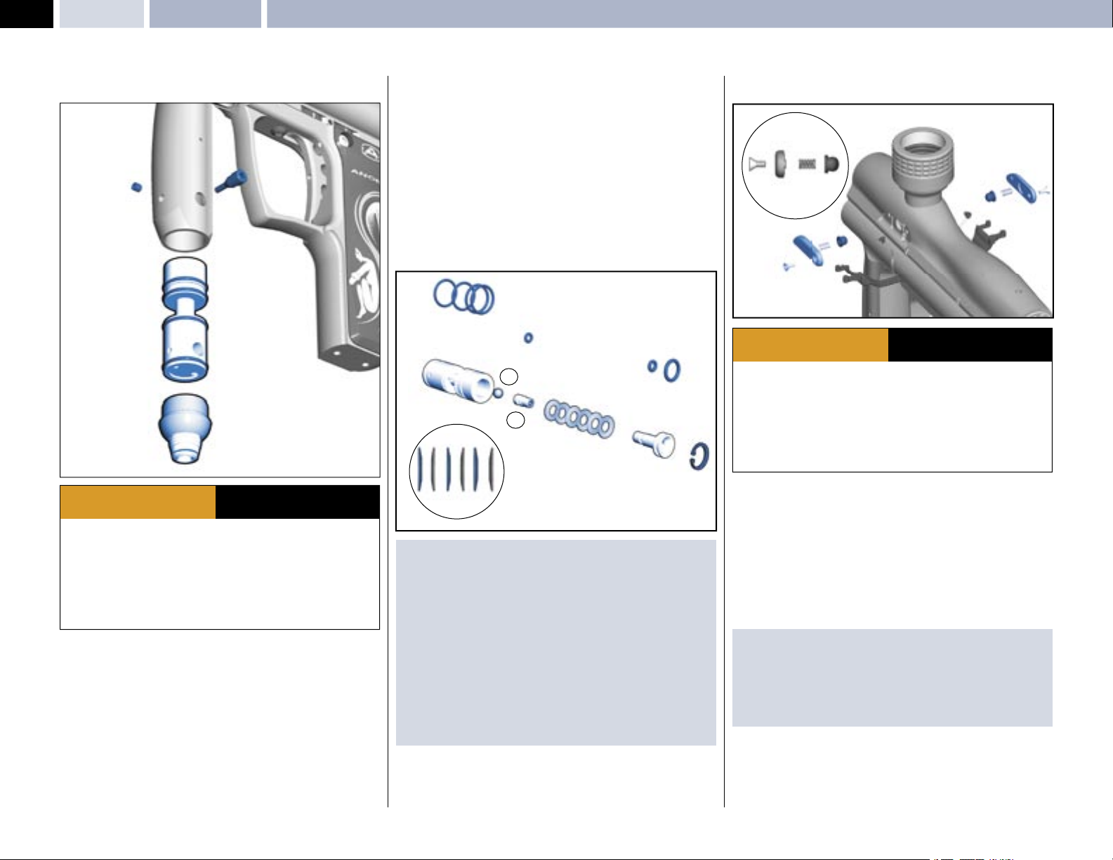
MINI-REGULATOR SERVICE
(2nd Stage Regulator)
2
1
6
5
3
4
ADHERE STRICTLY TO THESE
WARNING
· Ensure a barrel blocking device is fi tted to the ANGEL.
· Ensure the hopper is removed from the ANGEL.
· Ensure that there are no paintballs in the ANGEL.
· Always remove the fi rst stage regulator and relieve all residual gas pressure
from the ANGEL before disassembly.
· The ANGEL can hold a small residual charge of gas, typically 2 shots, with the
fi rst stage regulator removed. Always discharge the marker in a safe direction to
relieve this residual gas pressure.
The mini-regulator is a second stage regulator that is used to control the velocity
and regulate the gas pressure. It can be deleted, but only if a suitable fi rst stage
regulator is used that incorporates a high fl ow and good regulation properties
across the tank pressure range.
• Remove the macro line hose from the mini regulator by following the
procedure and warnings given in PROPELLANT AIR/NITROGEN SUPPLY
- Page 4.
• Remove the mini-regulator adjuster screw
• Remove the mini regulator locking screw
• Remove the mini regulator end cap
macro line fi tting
1 and rotating counter clockwise.
AND ALL OTHER SAFETY
INSTRUCTIONS AND GUIDELINES
1.
2.
3 by inserting a M4 allen key into the
• Insert an M3 screw into the threaded hole in the bottom of the spool and
gently extract the spool
• Remove the circlip 7 located in the spool using suitable circlip pliers.
• Invert the mini-regulator spool and tap it down fi rmly onto a smooth surface to
shock the internals out of the mini-regulator body.
• Ensure the large piston
bearing 11 are removed.
• Inspect the O rings for damage and replace if necessary.
• Inspect the small piston
small piston if necessary.
• Inspect the large piston
and replace as necessary.
9
6.
8, Spring stack 9, small piston 10, and the ball
10 face seal for damage and replace the whole
8 and small piston 10 sealing faces for damage
11
10
9
8
7
SPRING STACK
ORDER
IMPORTANT NOTES: For re-assembly of components
· Due care and attention must be shown to ensure you do not score or
damage the bores within the mini-regulator body whilst performing
maintenance.
· If the small piston or large piston seal faces are damaged they must be
replaced.
· We recommend that you lubricate the parts during re-assembly with Love
Juice Extreme Grease.
· Ensure the spring stack is in the correct order.
· Ensure the circlip is re-located correctly in the groove.
· Ensure you follow the procedure and warnings given in PROPELLANT AIR/
NITROGEN SUPPLY - Page 4, when re-attaching the micro-line hose.
ANTI - DOUBLE BALL DETENT SERVICE
2
1
1
3
2
3
ADHERE STRICTLY TO THESE
WARNING
· Ensure a barrel blocking device is fi tted to the ANGEL.
· Ensure the hopper is removed from the ANGEL.
· Ensure that there are no paintballs in the ANGEL.
· Always remove the fi rst stage regulator and relieve all residual gas pressure
from the ANGEL before disassembly.
· The ANGEL can hold a small residual charge of gas, typically 2 shots, with the
fi rst stage regulator removed. Always discharge the marker in a safe direction
to relieve this residual gas pressure.
There are two anti-double ball assemblies that can be removed and the internal
parts serviced if necessary. These are located on either side of the body below
the feed tube.
• Using a 2.0mm Allen key, remove the covers
• Remove the spring 2.
• Remove the anti-double ball 3.
• Repeat for other side.
• Inspect parts and replace if necessary.
IMPORTANT NOTES: For re-assembly of components
· Ensure the anti-double ball is re-located correctly.
· Ensure the spring is located correctly onto the anti-double ball.
· Ensure the anti-double ball covers are inserted correctly into the ANGEL
body.
· Ensure that the Angel Eyes are not moved or trapped.
AND ALL OTHER SAFETY
INSTRUCTIONS AND GUIDELINES
1.
© 2004 WDP LTD.
Page 13
ANGEL EYES
6
ANGEL Eyes Service & Removal MAINTENANCE
7
SPEED 05
13
1
2
5
3
4
ADHERE STRICTLY TO THESE
WARNING
· Ensure a barrel blocking device is fi tted to the ANGEL.
· Ensure the hopper is removed from the ANGEL.
· Ensure that there are no paintballs in the ANGEL.
· Always remove the fi rst stage regulator and relieve all residual gas pressure
from the ANGEL before disassembly.
· The ANGEL can hold a small residual charge of gas, typically 2 shots, with the
fi rst stage regulator removed. Always discharge the marker in a safe direction to
relieve this residual gas pressure.
The ANGEL uses a dual optical eye (break beam) system to detect when a ball is
in position and ready to fi re.
SERVICE Prior to servicing the Angel Eyes you should carry out the Angel Eye
test to ensure that they are not functioning prior to servicing. See Angel Eye
Test - Right. The Angel Eyes are located under the same cover plates as the
anti double balls and the internal parts can be serviced if necessary. These are
located on either side of the body below the feed tube.
• Using a 2.0mm Allen key, remove the covers
• Remove the anti double ball assembly
• Carefully remove the rubber protective strap from its location
• Carefully extract the Angel Eye
• NOTE: The Angel Eyes sensor MUST NOT be PULLED out of the body by the
ribbon cable, the sensor MUST be PUSHED out using a suitable blunt pick
from within the body.
• Inspect parts and clean if necessary.
IMPORTANT NOTES: For re-assembly of components
· Ensure the anti-double ball is re-located correctly.
· Ensure the spring is located correctly onto the anti-double ball.
· Ensure the cover plates are inserted correctly into the ANGEL body
· Ensure that the Angel Eyes are not moved or trapped.
5 from its location hole and clean if necessary.
AND ALL OTHER SAFETY
INSTRUCTIONS AND GUIDELINES
1.
2 3.
4.
8
8
9
ADHERE STRICTLY TO THESE
WARNING
· Ensure a barrel blocking device is fi tted to the ANGEL.
· Ensure the hopper is removed from the ANGEL.
· Ensure that there are no paintballs in the ANGEL.
· Always remove the fi rst stage regulator and relieve all residual gas pressure
from the ANGEL before disassembly.
· The ANGEL can hold a small residual charge of gas, typically 2 shots, with the
fi rst stage regulator removed. Always discharge the marker in a safe direction to
relieve this residual gas pressure.
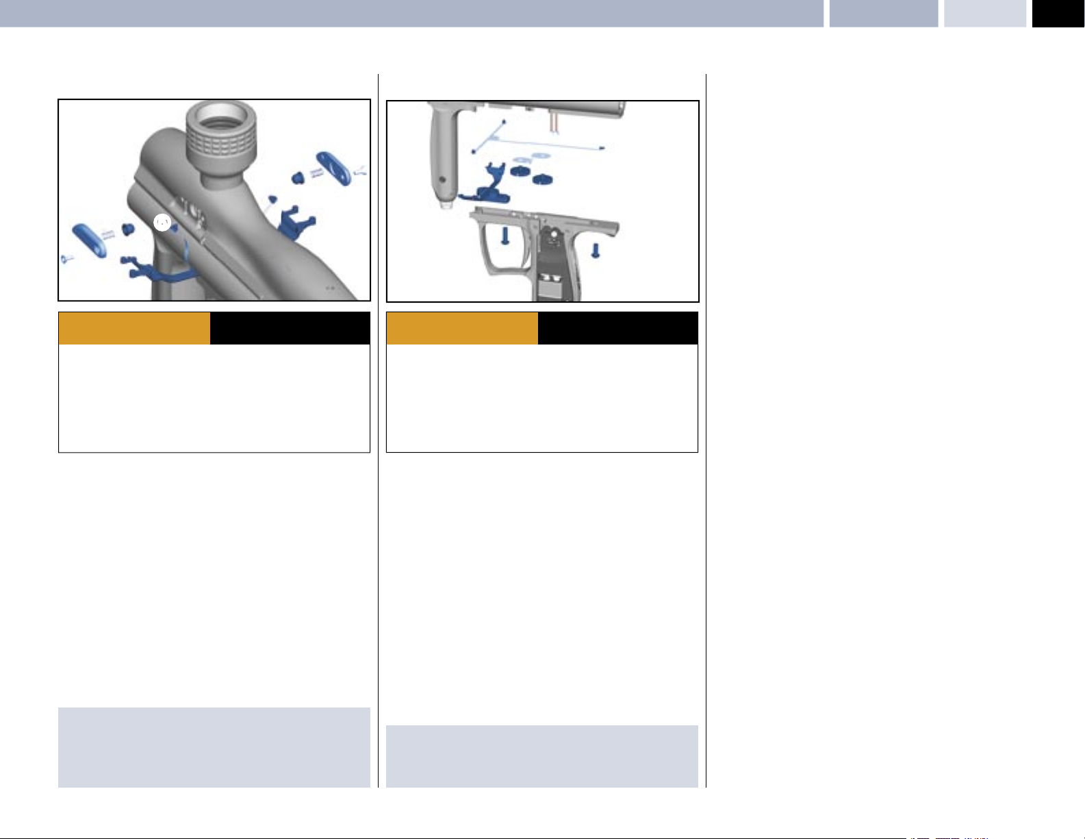
ANGEL EYES REMOVAL
• Remove the grip cheek cover by removing the 6 retaining screws using a
metric 2.5mm A/F Allen key.
• Unplug the battery and solenoid plugs from the PCB
• Remove the Angel Eyes ribbon cable
circuit board.
• Remove the Anti double ball covers
A/F Allen key.
• Remove the Angel Eyes Shields
• Remove the 2 grip frame screws
suitable 3mm A/F Allen key.
• Remove the grip frame from the body
NOTE: The Angel Eyes sensor MUST NOT be PULLED out of the body by the
ribbon cable, the sensor MUST be PUSHED out using a suitable blunt pick from
within the body.
IMPORTANT NOTES: For re-assembly of components
· Ensure no wires become trapped between the body and grip frame during
re-assembly.
· Ensure the plugs are located in the correct sockets.
4 and its sensors 5 from the body.
8 holding the frame to the body using a
AND ALL OTHER SAFETY
INSTRUCTIONS AND GUIDELINES
6.
7 from the ZIF socket on the
1,2,3 using a metric 2.0 mm
9.
© 2004 WDP LTD.
Page 14
14
SPEED 05
LPR AdjustmentMAINTENANCE
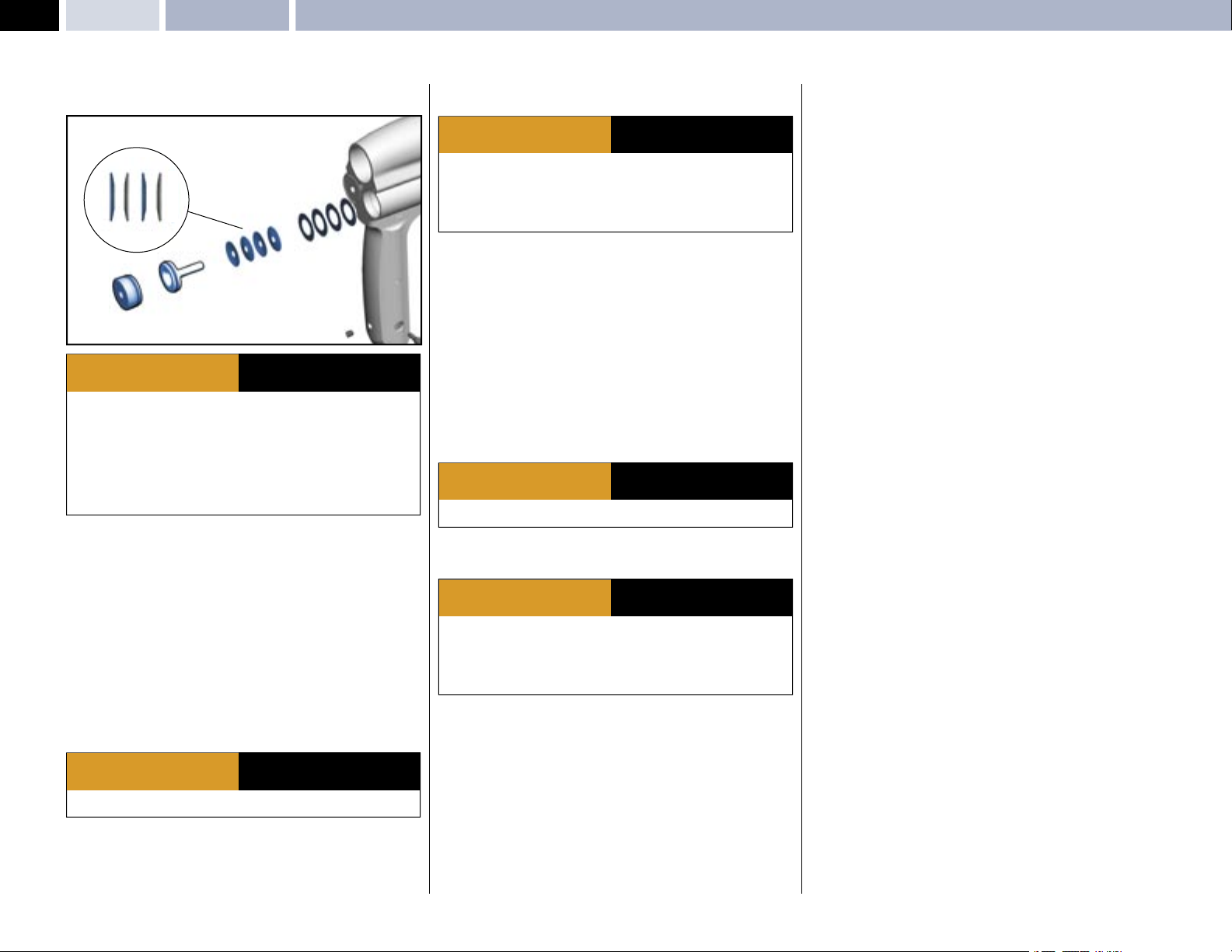
LPR ADJUSTMENT
3
4
SPRING STACK
ORDER
2
1
ADHERE STRICTLY TO THESE
WARNING
· Ensure a barrel blocking device is fi tted to the ANGEL.
· Ensure the hopper is removed from the ANGEL.
· Ensure that there are no paintballs in the ANGEL.
· Always remove the fi rst stage regulator and relieve all residual gas pressure
from the ANGEL before disassembly.
· The ANGEL can hold a small residual charge of gas, typically 2 shots, with the
fi rst stage regulator removed. Always discharge the marker in a safe direction to
relieve this residual gas pressure.
The low-pressure regulator controls the pneumatic cycle of the ANGEL and is
located in the left-hand chamber at the front of the ANGEL body. The pressure
needs to be at 65 PSI (4.5bar) output at a pressure of 350 PSI at the second
stage regulator.
LPR adjustment is achieved by the removal of shims. Each shim
equalsapproximately 5 PSI/0.35 BAR. We recommend the use of the optional
service tools and lubrication of parts with Love Juice Extreme Grease only. See
General Assembly diagrams - pages 10-11.
• Ensure the ANGEL is de-gassed and switched OFF.
• Remove the left end cap
• Insert the optional pressure gauge adaptor into the hole that the end cap
was removed from.
• Re-Gas the ANGEL and switch the isolator switch ON.
1 using suitable metric 4.0 A/F Allen key.
WARNING
· THE ANGEL IS LIVE AND CAPABLE OF DISCHARGING.
AND ALL OTHER SAFETY
INSTRUCTIONS AND GUIDELINES
ADHERE STRICTLY TO THESE
AND ALL OTHER SAFETY
INSTRUCTIONS AND GUIDELINES
1
ADHERE STRICTLY TO THESE
WARNING
· Always remove the fi rst stage regulator and relieve all residual gas pressure
from the ANGEL before disassembly.
· The ANGEL can hold a small residual charge of gas, typically 2 shots, with the
fi rst stage regulator removed. Always discharge the marker in a safe direction to
relieve this residual gas pressure.
• Ensure the ANGEL is de-gassed and switched OFF.
v Remove the pressure gauge adaptor and insert an M 2.5mm screw or the
piston extracting tool (optional extra) into the brass piston 2 and withdraw
slowly.
• Remove the four piston springs
• Add or subtract shims as necessary, note the number of shims may vary from
the diagram shown (maximum 20).
• Replace piston springs 3 in correct order onto the piston 2.
• Re-insert the piston 2 ensuring that it is located correctly.
• Insert the optional pressure gauge adaptor into the hole that the end cap
was removed from.
• Re-Gas the ANGEL and switch the isolator switch ON.
3.
WARNING
· THE ANGEL IS LIVE AND CAPABLE OF DISCHARGING.
Verify the LPR pressure by following the procedure described above. Once the
desired pressure has been achieved proceed to the next stage.
WARNING
· Always remove the fi rst stage regulator and relieve all residual gas pressure
from the ANGEL before disassembly.
· The ANGEL can hold a small residual charge of gas, typically 2 shots, with the
fi rst stage regulator removed. Always discharge the marker in a safe direction to
relieve this residual gas pressure.
• Ensure the ANGEL is de-gassed and switched OFF.
•Remove the pressure gauge adaptor & replace the end cap
AND ALL OTHER SAFETY
INSTRUCTIONS AND GUIDELINES
ADHERE STRICTLY TO THESE
AND ALL OTHER SAFETY
INSTRUCTIONS AND GUIDELINES
ADHERE STRICTLY TO THESE
AND ALL OTHER SAFETY
INSTRUCTIONS AND GUIDELINES
1.
1
· Fire 6 shots with NO paintballs present to stabilize the LPR pressure. Note
the pressure reading. Should the reading be too high or low, proceed to the
next stage.
© 2004 WDP LTD.
Page 15
MAINTENANCELPR Assembly Removal – LPR Main Seal Replacement
SPEED 05
15
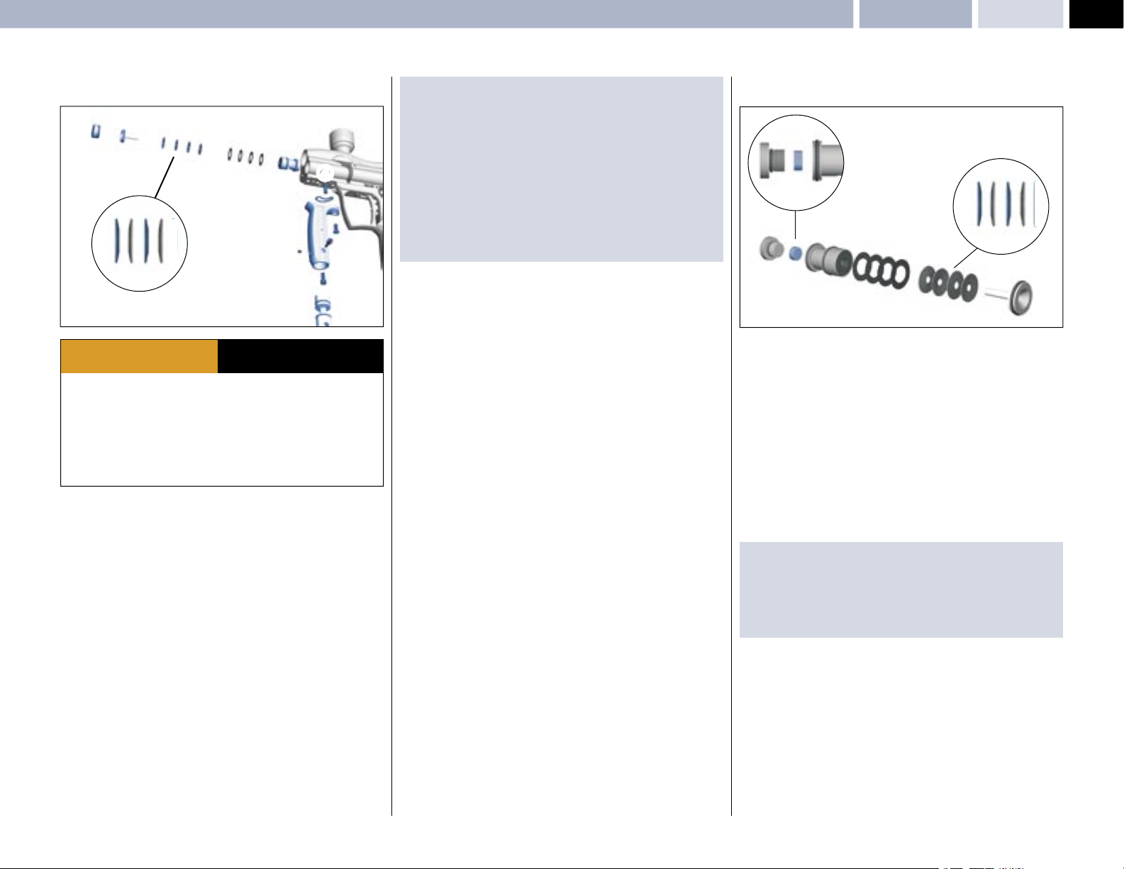
LPR ASSEMBLY REMOVAL
6
5
7
8
9
4
3
7
2
SPRING STACK
ORDER
ADHERE STRICTLY TO THESE
WARNING
· Ensure a barrel blocking device is fi tted to the ANGEL.
· Ensure the hopper is removed from the ANGEL.
· Ensure that there are no paintballs in the ANGEL.
· Always remove the fi rst stage regulator and relieve all residual gas pressure
from the ANGEL before disassembly.
· The ANGEL can hold a small residual charge of gas, typically 2 shots, with the
fi rst stage regulator removed. Always discharge the marker in a safe direction to
relieve this residual gas pressure.
• Remove the mini regulator spool as per mini regulator service - Page 12 .
• Remove the fore grip body internal retaining screw
A/F Allen key.
• Remove fore grip body external retaining screw
A/F Allen key.
• Ensure the O ring
• Remove LPR retaining pin using suitable grips
• Remove the right end cap
• Insert an M 2.5mm screw or the piston extracting tool (optional extra)
into the brass piston 6 and withdraw slowly.
• Remove the 4 piston spring stack 7.
• Remove the shims
diagram.
• Using a suitable blunt pick, carefully withdraw the LPR body
3 is not lost.
5 using suitable metric 4.0mm A/F Allen key.
8 - Note: the number of shims may vary from shown
AND ALL OTHER SAFETY
INSTRUCTIONS AND GUIDELINES
1 using a 4.0mm
2 using a 3.0mm
4.
1
9.
MPORTANT NOTES: For re-assembly of components
· Care must be taken so that the bore is not scored or the seals damaged.
· Ensure the LPR’s pin location hole is aligned with the pin retaining hole within
the ANGEL body prior to insertion.
· Ensure the spring stack is inserted in the correct order.
· We recommend that you verify your LPR pressure if it has been removed.
See LPR ADJUSTMENT - Page 14.
· Ensure the end cap is located correctly.
· Ensure the springs or shims are not lost (see LPR assembly).
Insert or remove shims as necessary.
· Each shim equals approximately 5 PSI/0.35 BAR.
LPR MAIN SEAL REPLACEMENT
RADIUS
2
SPRING STACK
ORDER
6
6
5
4
5
4
3
1
The LPR may be serviced once it has been removed by following the LPR
ASSEMBLY REMOVAL - Left. The serviceable parts are the external O rings and
the internal main seal.
• Remove the LPR piston 1.
• Remove the LPR spring stack 2 noting the order.
• Remove the LPR shims
diagram.
• Remove the LPR main seal retainer nut
suitable tool. To prevent the body from rotating in your hand you may insert
the LPR lock pin into the LPR body to give some leverage.
• Remove the main seal 5 noting the radius on the edge of the seal.
• Discard the main seal 5 and replace with new item.
IMPORTANT NOTES: For re-assembly of components
· Ensure the new main seal is replaced with the radius edge going in fi rst.
· Ensure the seal retainer nut is tight and fl ush with the LPR body.
· Ensure the spring stack is in the correct order.
· Ensure that the LPR pressure is reset as per LPR ADJUSTMENT - Page 14.
3 Note: the number of shims may vary from shown
6 from the LPR body 4 using a
© 2004 WDP LTD.
Page 16
16
SPEED 05
Exhaust Guide Removal – Exhaust Valve Stem Removal MAINTENANCE
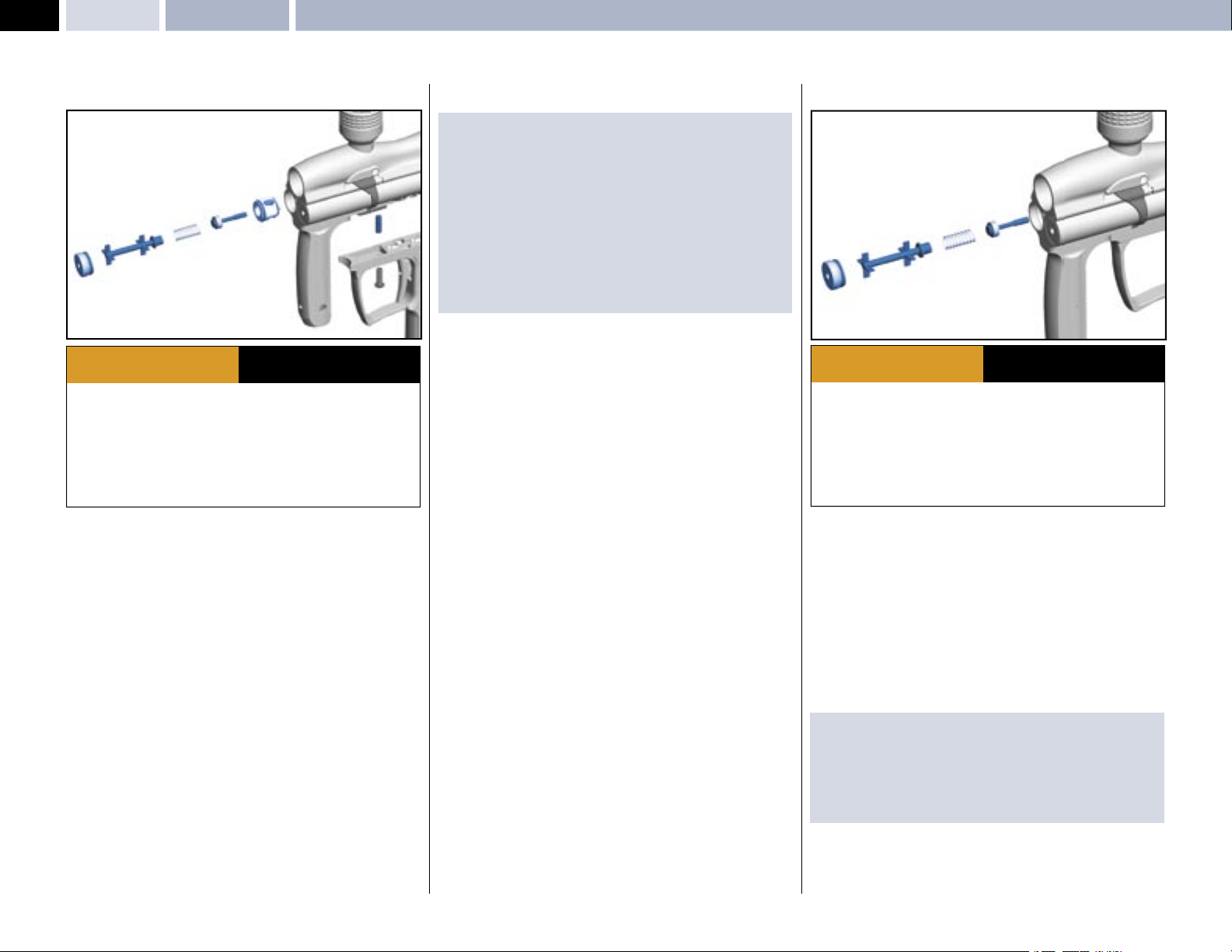
EXHAUST GUIDE REMOVAL
7
6
5
4
3
1
ADHERE STRICTLY TO THESE
WARNING
· Ensure a barrel blocking device is fi tted to the ANGEL.
· Ensure the hopper is removed from the ANGEL.
· Ensure that there are no paintballs in the ANGEL.
· Always remove the fi rst stage regulator and relieve all residual gas pressure
from the ANGEL before disassembly.
· The ANGEL can hold a small residual charge of gas, typically 2 shots, with the
fi rst stage regulator removed. Always discharge the marker in a safe direction to
relieve this residual gas pressure.
• Remove the grip cheek cover by removing the 6 retaining screws
using a metric 2.5mm A/F Allen key.
• Unplug the Angel Eyes, battery and solenoid plugs.
• Remove the 2 grip frame screws holding the frame to the body using a
suitable 3mm A/F Allen key.
• Remove the grip frame
• Pull out the exhaust valve retaining pin
grips.
• Remove the left end cap
• Remove the valve spring support bobbin
• Remove the valve spring 5.
• Remove exhaust valve stem 6.
• Using a suitable blunt hooked pick carefully retract exhaust valve guide
by inserting the pick into the exhaust valve hole that the exhaust valve stem
located into.
• Inspect and service parts as necessary.
1 from the body.
3 using suitable metric 4.0mm A/F Allen key.
AND ALL OTHER SAFETY
INSTRUCTIONS AND GUIDELINES
2 located in the body using suitable
4 .
EXHAUST VALVE STEM REMOVAL
IMPORTANT NOTES: For re-assembly of components
· Care must be taken so that the bore is not scored or the seals damaged.
· Ensure the exhaust valve guide body is free from damage that may score the
bore.
· Ensure you do not damage the exhaust valve guide sealing face.
· Ensure the location hole in the exhaust valve guide is in the correct
2
orientation to the lock hole within the main body prior to refi tting.
· Slowly insert the valve guide pushing it down with a blunt soft faced rod.
· When the holes line up insert the lock pin into the hole.
· Ensure no wires become trapped between the body and grip frame during
re-assembly.
· Ensure the plugs are located in the correct sockets.
1
2
3
WARNING
· Ensure a barrel blocking device is fi tted to the ANGEL.
· Ensure the hopper is removed from the ANGEL.
· Ensure that there are no paintballs in the ANGEL.
· Always remove the fi rst stage regulator and relieve all residual gas pressure
from the ANGEL before disassembly.
· The ANGEL can hold a small residual charge of gas, typically 2 shots, with the
fi rst stage regulator removed. Always discharge the marker in a safe direction to
relieve this residual gas pressure.
The exhaust valve stem is a consumable item that will eventually wear out.
Premature failure of the exhaust valve stem is caused by dirty air or failure to
lubricate it at service intervals, to replace the exhaust valve stem follow the
procedures listed below.
1 or volumizer using suitable metric 4.0mm
7
• Remove the left end cap
A/F Allen key.
• Remove the valve spring support bobbin
• Remove the valve spring 3.
• Remove exhaust valve stem 4.
IMPORTANT NOTES: For re-assembly of components
· Ensure exhaust valve is located in exhaust body within the ANGEL.
· Ensure the spring is located onto the exhaust valve stem .
· Ensure the spring is located onto the valve spring support bobbin .
· Ensure the end cap is located correctly.
4
ADHERE STRICTLY TO THESE
AND ALL OTHER SAFETY
INSTRUCTIONS AND GUIDELINES
2.
© 2004 WDP LTD.
Page 17
MAINTENANCERam Stroke Adjustment – Ram Removal – Ram Servicing
SPEED 05
17
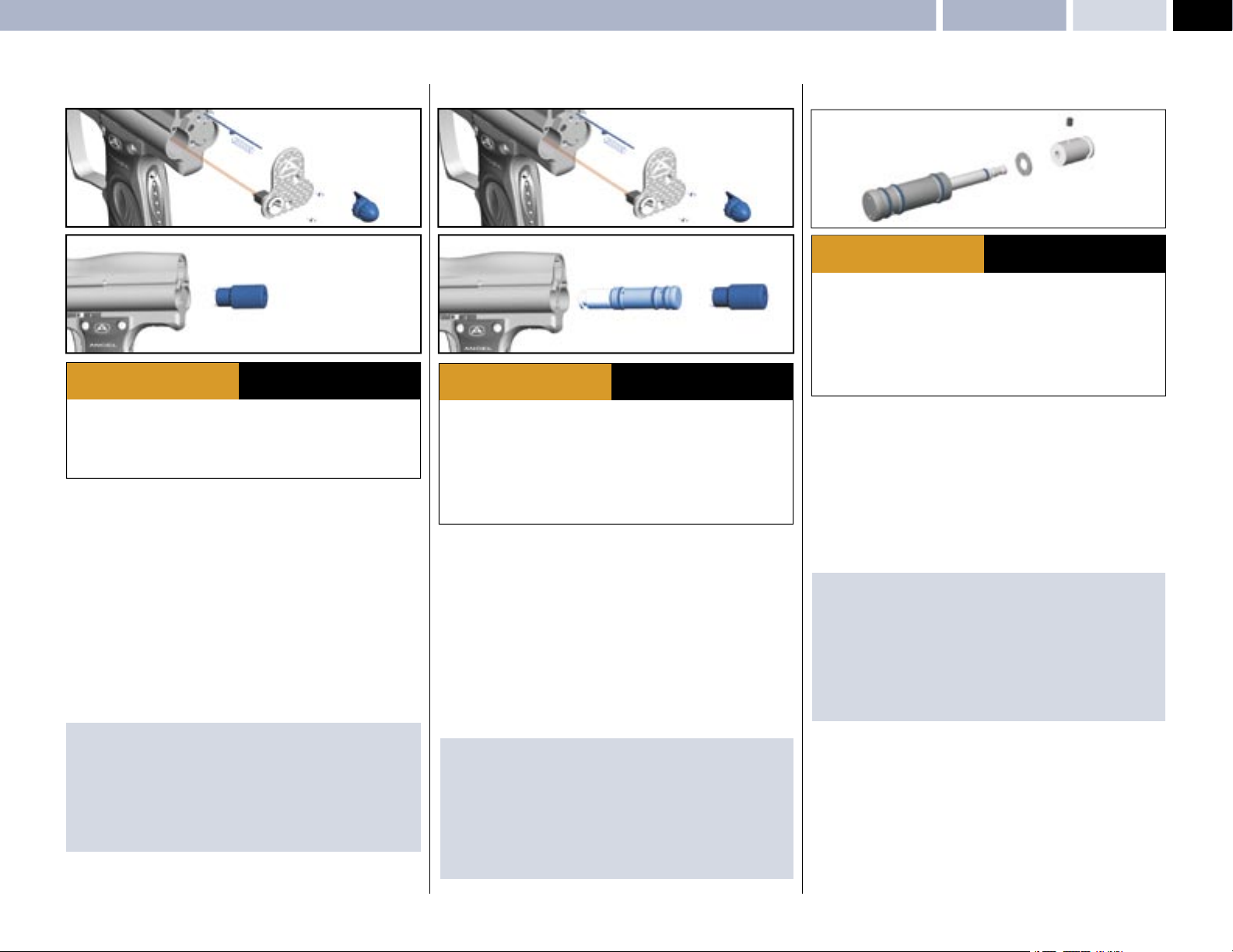
RAM STROKE ADJUSTMENT
5
3
4
2
1
2
6
ADHERE STRICTLY TO THESE
WARNING
· Ensure a barrel blocking device is fi tted to the ANGEL.
· Ensure the hopper is removed from the ANGEL.
· Ensure that there are no paintballs in the ANGEL.
• Ensure the ANGEL is gassed and switched OFF.
• Ensure bolt is fully retracted.
• Remove the breech block pull knob
counter-clockwise.
• Remove the countersunk screws
Allen key.
• Carefully lift the back plate
• Retract the spring 4 and breech block lock pin 5.
• Using circlip pliers or the ram location tool
assemblies clockwise until slight resistance is felt in opening the breech
block. If rotated too far the breech will not open so rotate counter-clockwise
and repeat operation. The ram must always be rotated clockwise when setting.
IMPORTANT NOTES: For re-assembly of components
· There are wires and a spring is located under the back plate . Care must be
taken so that the wires are not pulled or trapped during maintenance.
· The ram must always be rotated clockwise when setting.
· Ensure the spring is replaced correctly
· Ensure the breech block opens correctly after refi tting the breech block knob
· Ensure that no wires become trapped during re-assembly.
2, using a suitable 2.0mm A/F metric
3 off.
AND ALL OTHER SAFETY
INSTRUCTIONS AND GUIDELINES
1 by gently pulling and unscrewing
6 optional accessory rotate ram
RAM REMOVAL
5
3
4
2
1
2
7
ADHERE STRICTLY TO THESE
WARNING
· Ensure a barrel blocking device is fi tted to the ANGEL.
· Ensure the hopper is removed from the ANGEL.
· Ensure that there are no paintballs in the ANGEL.
· Always remove the fi rst stage regulator and relieve all residual gas pressure
from the ANGEL before disassembly.
· The ANGEL can hold a small residual charge of gas, typically 2 shots, with the
fi rst stage regulator removed. Always discharge the marker in a safe direction to
relieve this residual gas pressure.
• Ensure the ANGEL is de-gassed and switched OFF.
• Open the breech block and remove the bolt.
• Remove the breech block pull knob
counter-clockwise.
• Remove the countersunk screws
Allen key.
• Carefully lift the back plate off
• Retract the spring 4 and breech block lock pin .
• Using circlip pliers or the ram location tool
rotate ram assembly counter clockwise
IMPORTANT NOTES: For re-assembly of components
· There are wires and a spring is located under the back plateCare must be
taken so that the wires are not pulled or trapped during maintenance.
· Ensure the ram assembly is lubricated with Love juice Extreme Grease prior
to re-fi tment.
· Ensure the ram assembly external O rings are not damaged.
· Ensure the ram assembly is inserted slowly to prevent damage to the O rings.
· See RAM STROKE ADJUSTMENT - Left, for setting the ram position.
2, using a suitable 2.0mm A/F metric
3.
AND ALL OTHER SAFETY
INSTRUCTIONS AND GUIDELINES
1 by gently pulling and unscrewing
6 (optional accessory)
7 and withdraw the ram.
6
RAM SERVICING
1
4
3
2
5
ADHERE STRICTLY TO THESE
WARNING
· Ensure a barrel blocking device is fi tted to the ANGEL.
· Ensure the hopper is removed from the ANGEL.
· Ensure that there are no paintballs in the ANGEL.
· Always remove the fi rst stage regulator and relieve all residual gas pressure
from the ANGEL before disassembly.
· The ANGEL can hold a small residual charge of gas, typically 2 shots, with the
fi rst stage regulator removed. Always discharge the marker in a safe direction to
relieve this residual gas pressure.
The ram must be removed as per RAM REMOVAL – Left, prior to servicing.
The ram has three components that may be replaced these are the following:
Hammer, Bumper, Ram clamp seal and Ram Body O rings .
• Remove the ram hammer lock screw
Allen key.
• Remove the hammer 2 from the ram rod 3 using suitable SOFT faced grips.
• Remove the bumper 4 and inspect for damage, replace if necessary.
• Remove the ram clamp seal 5 and replace.
IMPORTANT NOTES: For re-assembly of components
· The ram clamp seal must be replaced with a new item if removed.
· We recommend that Loctite medium strength adhesive is applied to the
hammer if removed.
· We recommend that Loctite medium strength adhesive is applied to the
hammer lock screw if removed.
· We recommend that you lubricate the ram shaft with Love Juice
Extreme Grease.
AND ALL OTHER SAFETY
INSTRUCTIONS AND GUIDELINES
1 using a suitable 2.0 mm metric
© 2004 WDP LTD.
Page 18
18
SPEED 05
Vernier Trigger Adjustments
MAINTENANCE
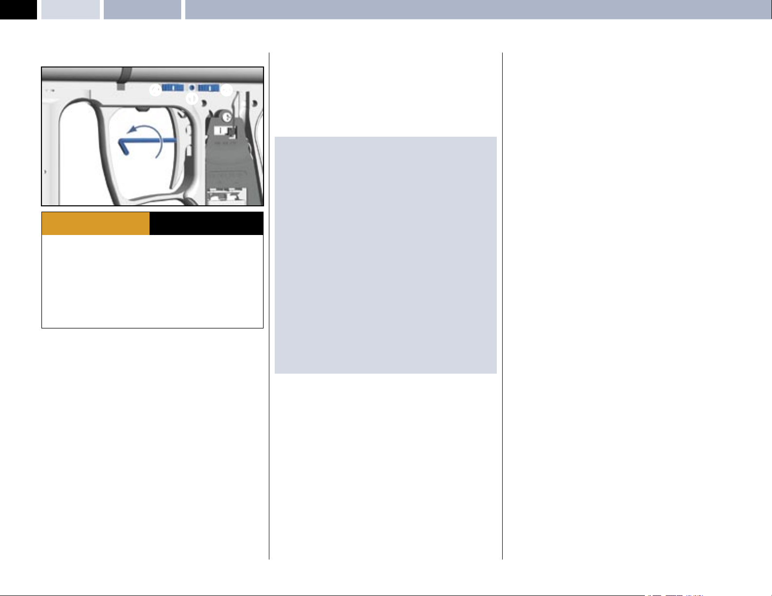
VERNIER TRIGGER ADJUSTMENTS
4
3
1
2
ADHERE STRICTLY TO THESE
WARNING
· Ensure a barrel blocking device is fi tted to the ANGEL.
· Ensure the hopper is removed from the ANGEL.
· Ensure that there are no paintballs in the ANGEL.
· Always remove the fi rst stage regulator and relieve all residual gas pressure
from the ANGEL before disassembly.
· The ANGEL can hold a small residual charge of gas, typically 2 shots, with the
fi rst stage regulator removed. Always discharge the marker in a safe direction to
relieve this residual gas pressure.
· Never adjust your trigger so fi ne that accidental discharge can occur due to
shock loads or vibration.
The trigger return stroke, over-travel and toe adjustments should be carried
out in the order shown and will enable the user to have total adjustment on the
tactile feel and trigger movement.
• Using a suitable Allen key undo the trigger adjustment locking screw
located between the thumb wheels by rotating counter clockwise.
• Remove the grip cheek retaining screws and expose the circuit board
• Using a suitable Allen key back off the toe adjustment screw
counter clockwise, now the trigger return stroke and over travel may be set.
• The vernier thumb wheel located at the top of the grip frame closest to the
rear of the ANGEL
• By viewing the ANGEL on the left hand side of the body rotate the thumb
wheel closest to the rear of the ANGEL slowly towards the rear of the ANGEL
each click at a time, this will reduces the over travel each click will be an
incremental reduction in the stroke.
• The vernier thumb wheel located at the top of the grip frame furthest to the
rear of the ANGEL
• By viewing the ANGEL on the left hand side of the body rotate the thumb
wheel furthest from the rear of the ANGEL slowly towards the rear of the
ANGEL each click at a time, this will reduces the return stroke, each clickwill
be an incremental reduction in the stroke.
3 controls the over-travel
4 controls the return stroke
AND ALL OTHER SAFETY
INSTRUCTIONS AND GUIDELINES
1
2 by rotating
• Further fi ne tuning can be achieved by adjusting the toe adjuster screw 2.
Clockwise will cause the trigger to activate with less trigger movement counter
clockwise will result in a longer trigger stroke within the limits set by vernier
thumb wheels.
• Verify the trigger is functioning correctly.
• Replace grip cheek cover screws using a suitable metric Allen key.
• Very gently tighten the vernier thumb wheel locking screw.
IMPORTANT NOTES: For re-assembly of components
· There must be suffi cient over travel to activate the OPTO board, otherwise
the opto-trigger will not operate correctly
· There must be suffi cient return stroke to reset the OPTO board otherwise the
opto-trigger will not operate correctly.
· Should the trigger be incorrectly adjusted, re-adjust the return stroke
by repeating the procedures listed above or re-adjust the over travel by
repeating the procedures listed above.
· When adjusting the trigger stroke we recommend you apply a small amount
of Loctite low strength thread lock to the toe adjuster screw to prevent
movement due to vibration prior to adjustment.
· The toe adjuster screw must not be over-adjusted as damage may occur to
the actuation.
· The vernier locking screw must not be over tightened otherwise damage may
occur to the vernier retention springs.
· The OPTO board is a non-mechanical switch that is silent in its operation and
no audible click is present.
· The OPTO board should not be exposed to direct sunlight or external strong
sources of light without the grip cheek fi tted as this light will induce a safety
feature, that will prevents the ANGEL from fi ring whilst it remains exposed to
the external strong light.
· Never adjust the trigger stroke so that the trigger has so fi ne a movement
that accidental discharges may occur or that trigger bounce may occur
leading to accidental discharges.
© 2004 WDP LTD.
Page 19
VERNIER TRIGGER WHEEL REMOVAL
Vernier Trigger Wheel Removal MAINTENANCE
SPEED 05
19
4
1
1
7
3
5
1
6
2
7
2
2
3
1
A
5
A
6
1
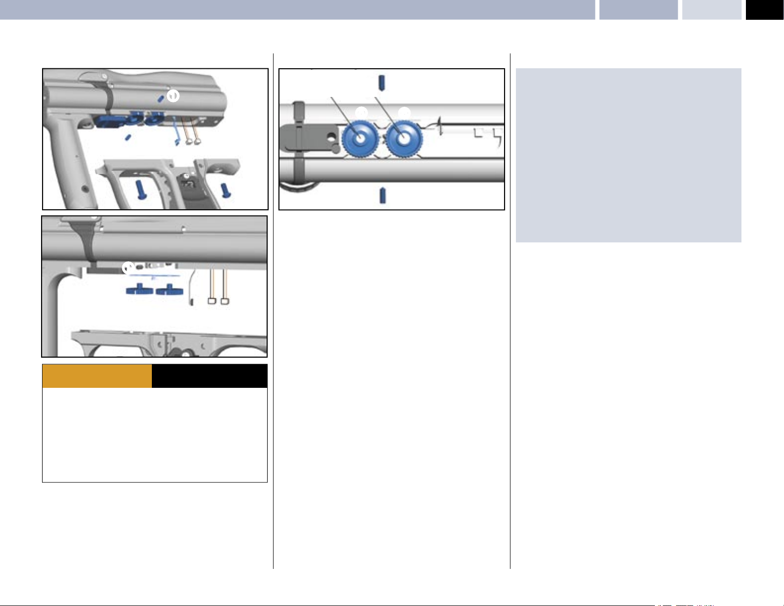
• Undo the vernier wheel lock screws 1 using a suitable allen key.
• Important: Note the vernier wheels position prior to removal.
• Remove the grip cheek cover by removing the 6 retaining screws and using a
metric 2.5mm A/F Allen key.
• Unplug the Angel Eyes, battery and solenoid plugs
• Remove the 2 grip frame screws
suitable 3mm A/F Allen key.
• Remove the grip frame
• Gently remove the vernier wheels
• Remove the vernier wheel ratchet plates
3 holding the frame to the body using a
4 from the body.
5,6 from the body.
2.
7 and inspect for damage.
IMPORTANT NOTES: For re-assembly of components
· Should you be unsure of the original position of the vernier wheels follow the
procedure listed below for re-assembly.
· Ensure the vernier wheel locking screws
counter clockwise.
· Ensure the vernier trigger toe adjuster screw is backed off by rotating counter
clockwise.
· It is important that the vernier wheels are inserted in position
above, wheel
Wheel
ensure that you start with maximum range of adjustment
· Verify the correct vernier wheel position by the indicators on the wheels
· Re-attach the frame.
· Ensure no wires become trapped between the body and grip frame during
re-assembly.
· Ensure the plugs are located in the correct sockets.
· Adjust the trigger as VERNIER TRIGGER ADJUSTMENT - Page 18.
5 with the small magnet towards the front of the ANGEL.
6 with the large magnet towards the rear of the ANGEL, this is to
1 are backed off by rotating
A shown
5
ADHERE STRICTLY TO THESE
WARNING
· Ensure a barrel blocking device is fi tted to the ANGEL.
· Ensure the hopper is removed from the ANGEL.
· Ensure that there are no paintballs in the ANGEL.
· Always remove the fi rst stage regulator and relieve all residual gas pressure
from the ANGEL before disassembly.
· The ANGEL can hold a small residual charge of gas, typically 2 shots, with the
fi rst stage regulator removed. Always discharge the marker in a safe direction to
relieve this residual gas pressure.
· Never adjust your trigger so fi ne that accidental discharge can occur due to
shock loads or vibration.
© 2004 WDP LTD.
AND ALL OTHER SAFETY
INSTRUCTIONS AND GUIDELINES
Page 20
20
SPEED 05
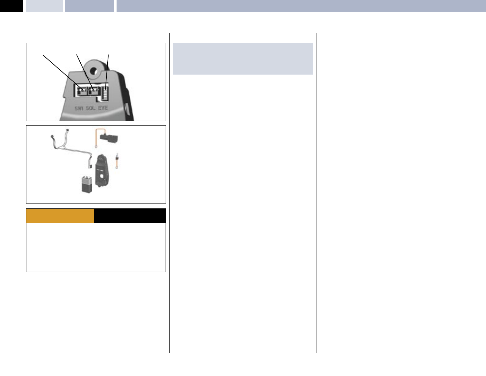
WIRING CONNECTIONS
Wiring ConnectionsMAINTENANCE
SWITCH SOLENOID EYES
ADHERE STRICTLY TO THESE
WARNING
· Ensure a barrel blocking device is fi tted to the ANGEL.
· Ensure the hopper is removed from the ANGEL.
· Ensure that there are no paintballs in the ANGEL.
· Always remove the fi rst stage regulator and relieve all residual gas pressure
from the ANGEL before disassembly.
· The ANGEL can hold a small residual charge of gas, typically 2 shots, with the
fi rst stage regulator removed. Always discharge the marker in a safe direction to
relieve this residual gas pressure.
AND ALL OTHER SAFETY
INSTRUCTIONS AND GUIDELINES
IMPORTANT NOTES: For re-assembly of components
· Do not trap any wiring or damage could occur to the wiring resulting in a
fault developing.
· Do not pull the plugs out from the PCB by the wiring use a suitable tool.
• Ensure the ANGEL is de-gassed and switched off.
• Remove the left-hand side grip cheek cover by removing the 3 screws using a
suitable metric Allen key.
• Access to the PCB connections is now gained.
© 2004 WDP LTD.
Page 21

APPENDICESFault Finding Table – Useful Conversions
SPEED 05
21
FAULT FINDING TABLE
PROBLEM SOLUTION PAGE
ANGEL WILL NOT FIRE
No air or nitrogen present? Propellant Air/Nitrogen Supply . 4
Is a good 9v battery present? Replacing the 9v Battery 3
Is the isolator switched off? Switching the ANGEL On. 3
Is the trigger not closing the switch? Trigger Adjustment. 18
Is the trigger not releasing the switch? Trigger Adjustment. 18
Is the bolt jammed forward? Clear the blockage from breech. –
Is the LPR set correctly? LPR Adjustment. 14
Is the OPTO Trigger functioning? Trigger Adjustment. 18
Are the connectors plugged in correctly? Wiring Connections 20
Are the Angel Eyes switched on? Ensure paint is present 4
Are the Angel Eyes optics blocked Clean the Angel Eyes Optics –
VELOCITY VARIATIONS
Are good quality paintballs been used? Use good paintballs. –
Is the barrel bore correct for the paint? Use suitable barrel. –
Is the paint swollen, cold or hot? Review your storage of paint. –
Is the barrel bore clean? Clean the barrel. –
Are the Anti-Double balls sticking? Check Anti-Double Ball 12
Is the tank reg choking on gas supply? Check tank regulator assembly. 4
Is the tank reg operating correctly? Check tank regulator assembly. 4
Is the mini-reg operating correctly? Mini-Regulator Service. 12
Is the mini-reg choking on gas supply? Mini-Regulator Service. 12
Are unsuitable after market parts fi tted? Use genuine ANGEL parts. –
Is the bolt worn? Replace Soft Bolt. 5
Is the LPR set correctly? LPR Adjustment. 14
Is the valve dwell set correctly? Dwell Adjustment. 7
Is the ram set correctly? Ram Stroke Adjustment. 17
Is fi rst shot low? Increase Dwell Time
VELOCITY TOO LOW / HIGH
Is the high pressure reg set correctly? Check at Gas source. 4
Is velocity adjuster screw set correctly? Velocity Adjustment. 6
Is the bolt sticking? Check Anti-Double Ball. 12
Is the LPR set correctly? LPR Adjustment. 14
Is the valve dwell set correctly? Dwell Adjustment. 7
Is the Ram set correctly? Ram Stroke Adjustment.
GAS LEAKING
From the back cover? Check solenoid valve. 10
From the Ram assembly? Check ram body O rings. 17
From the gas joints? Check all fi ttings.
From exhaust valve? Exhaust valve stem/guide. 1
7
17
6
PROBLEM SOLUTION PAGE
BREAKING PAINTBALLS
Is the paint too fragile? Use less fragile paint. –
Is the barrel bore correct for the paint? Use suitable barrel. –
Is the paint swollen, cold, hot? Review your storage of paint. –
Are the Angel Eyes switched on? Switching Angel Eyes On 4
Are the Angel Eyes functioning? Angel Eyes Test. 4
Is the loader battery weak/dead? Replace batteries. 5
Is a suitable working loader fi tted?
Is the correct loader setting selected? Change Loader Type settings 8
Is the anti-double balls functioning? Clean or replace. 12
Is the loader suitable for the paint? Change paint colour 5
Is the paint too fragile for the loader? Change paint to tougher grade 5
CHOPPING PAINTBALLS
Is the loader battery weak/dead Replace batteries. 5
Is a suitable working loader fi tted? Replace loader. 5
Is the loader dirty? Clean loader. 5
Are the paintballs swollen? Replace the paintballs. –
Are the Angel Eyes switched on? Switching Angel Eyes On 4
Are the Angel Eyes functioning? Angel Eyes Test. 4
Is the correct loader setting selected? Change Loader Type settings 8
Are the Anti-double balls functioning? Clean or replace.
FIRING TOO SLOW
Is the loader battery weak/dead? Replace batteries 5
Is a suitable working loader fi tted? Replace loader 5
Is the loader dirty? Clean loader 5
Are the Angel Eyes switched on? Switching Angel Eyes On 4
Is the correct loader setting selected? Change Loader Type settings 8
EXCESSIVE NOISE / GAS CONSUMPTION
Is the valve Dwell set correctly? Dwell Adjustment. 7
Is the LPR pressure set correctly? LPR Adjustment. 14
Is the exhaust valve worn? Exhaust Valve replacement. 16
Is the barrel bore correct for the paint? Use suitable barrel.
See Loader section 5
12
USEFUL CONVERSIONS
Listed are some useful conversions relating to pressure, velocity, mass
and distance.
PRESSURE
1 atm = 1.01325 bar
1 atm = 14.6959 psi
1 bar = 14.5038 psi
1 psi = 0.0689476 bar
VELOCITY
1 Ft/s = 0.3048 m/s
1 Ft/s = 0.6818180 Mph
1 m/s = 3.28084 Ft/s
1 m/s = 2.23694 Mph
1 m/s = 3.6 Kph
MASS
1 g = 0.05274 oz
1 Kg = 2.20462 Ib
1 oz = 0.0283495 Kg
DISTANCE
1 mm = 0.0393701 Inch
1 Inch = 25.4mm
1 thou = 25.4 micron
1 micron = 0.0393701 thou
FORMULA TO CONVERT FEET PER SECOND (FT/S)
TO FOOT LBS (FORCE)
1 foot Ibs (force) = 1.35582 Joules
1 Joule = 0.737562 foot Ibs (force)
1 Gram = 15.4324 Grains
1 Grain = 0.000142857 lb
1 lb = 7000 Grains
Velocity squared x Projectile weight
450240
VELOCITY = Ft/s (feet per second)
PROJECTILE WEIGHT = GRAINS
Therefore a paintball @ 3.2grams @ 300Ft/s= 9.9 foot lbs (ftlbs)
© 2004 WDP LTD.
Page 22

22
SPEED 05
Terms of Warranty: EEC/ROW Excluding USA/CanadaAPPENDICES
TERMS OF WARRANTY - EEC/R.O.W.
EXCLUDING USA / CANADA
Subject to the conditions set out below WDP Ltd. warrants that the ANGEL
will correspond to its specifi cation at the time of delivery and will be free from
defects in materials and workmanship for a period of six months from the date
of purchase.
WDP Ltd gives this warranty subject to the following conditions:
· Proof of purchase is required in all warranty claims.
· Warranty is not transferable.
· The company shall be under no liability in respect of any defect arising from
fair wear and tear.
· Seals, batteries, wiring, circuit boards, displays and exhaust valves are not
covered by this warranty. Wilful damage, negligence, abnormal working
conditions, weather, accident, tampering, failure to follow manufacturers
instructions (whether oral or in writing), misuse or alteration or repair of the
ANGEL without the company’s written approval will invalidate this warranty
and the company shall be under no obligation whatsoever to the purchaser in
respect of any of the above breaches of this warranty.
· The above warranty does not extend to parts, materials or equipment not
manufactured by the company, in respect of which the purchaser shall only
be entitled to the benefi t of any such warranty or guarantee as given by the
manufacturer to the company.
This warranty does not cover the following:
· Repairs, alterations or replacements not authorised by the manufacturer.
· The gradual reduction in performance linked to the age of the ANGEL or usage.
· Anything caused directly or indirectly by vandalism or theft.
· Any damage to parts which are recalled by the Manufacturer.
· Any loss, damage or failure, which a qualifi ed engineer appointed by the
Manufacturer, believes could have been avoided or was totally or partly caused
by a lack of maintenance.
Subject as expressly provided in these conditions and except where the goods
are sold to a person dealing as a consumer (within the meaning of the Unfair
Contract Terms Act 1977) all warranties, conditions or other terms implied by
statute or common law are excluded to the fullest extent permitted by law.
Where the goods are sold under a consumer transaction (as defi ned by the
Unfair Terms in Consumer Contracts Regulations 1994 S13159) the statutory
rights of the purchaser are not affected by these conditions. Carriage charges in
relation to warranty claims shall be borne by the customer.
Where any valid claim in respect of the ANGEL is based in the quality or
condition of the ANGEL or its failure to meet specifi cation, and such valid claim
is notifi ed to the company in writing and is in accordance with the company’s
standard terms and conditions of sale, the company shall be entitled to
repair or replace the goods or the part in question free of charge or, at the
company’s sole discretion, refund to the purchaser the price of the goods (or a
proportionate part of the price) but the company shall have no further liability to
the purchaser.
Except in respect of death or personal injury caused by the company’s
negligence, the company shall not be liable to the purchaser by reason of
any representation, or any implied warranty, condition or other term, or any
duty at common law, or under the express terms of this guarantee, for any
direct or indirect, special or consequential loss or damage, whether to persons
or property, costs, expenses or other claims for compensation or damages
whatsoever (whether caused by the negligence of the company, its employees
or agents or otherwise) which arise out of or in connection with the supply of
the ANGEL its use, or misuse, or resale by the purchaser, or any individual, and
the entire liability of the company under or in connection with the purchase or
use or misuse of the ANGEL shall not exceed the purchase price of the ANGEL.
Purchaser agrees to adhere strictly to all warnings and safety procedures and
the contents of the Operators Manual.
The laws of England shall govern this warranty and the purchaser agrees to
submit to the non-exclusive jurisdiction of the English courts.
The supply and purchase of the ANGEL is subject to the company’s standard
terms and conditions of sale, a copy of which is available on request. ANGEL
patents applied for, design rights and all rights reserved. The ANGEL is marketed
and distributed by WDP Ltd. company, registered in England No. 2114341.
No warranty is given to parts not manufactured by the manufacturer and all
liability for loss damage or injury is excluded.
This warranty must be construed and read in conjunction with the products
terms and conditions of sale.
To make a warranty claim, buyer must fi rst contact the nearest authorised
ANGEL Service Centre for instructions. A list of authorised ANGEL Service
Centres may be obtained through WDP Ltd. website: www.wdp.tv, or by
contacting WDP by mail at WDP Ltd., Metro Triangle,
221 Mount Street, Nechells, Birmingham, England, B7 5QT, or by fax at +(44)
(0)121 327 3967, or by calling +(44) (0)121 328 2228.
© 2004 WDP LTD.
Page 23

APPENDICESTerms of Warranty: WDP Ltd., Express Warranty USA/Canada Only
SPEED 05
23
WDP LTD. EXPRESS WARRANTY
USA / CANADA ONLY
1. General Express Warranties.
WDP Ltd. warrants to the buyer who is purchasing to place into use (Buyer) only,
that the ANGEL (Product) shall be free from material manufacturing defects in
materials and workmanship for six months from the date of purchase, subject
to the requirements, disclaimers and limitations of this Warranty. This is not
a Warranty of performance, but a limited Warranty as to the condition of the
Product at the beginning of the Warranty period, this Warranty is only against
such defects and not against any other failures such as, but not limited to,
those due to wear and tear, exposure to the elements, unusual operating
environments, misuse, negligence, accident, alteration or repair in any respect
which, in the judgement of WDP Ltd., adversely affects the condition or
operation of the Product. Normal maintenance and perishable items such as
seals, batteries, wiring, indicator lamps and exhaust valves are excluded from
this limited Warranty against defects. This Warranty is not transferable and
it may not be waived or expanded except in writing signed by WDP Ltd. The
terms and limitations of this Warranty shall also apply to any additional goods or
information, which may be distributed by WDP Ltd., relating to the ANGEL.
2. Disclaimer and Limitation of Express and Implied Warranties.
There are no express Warranties other than those contained in this Warranty.
Whether or not the Product is to be used exclusively by Buyer, there shall be no
third party benefi ciaries to this Warranty herein. NO WARRANTY IS PROVIDED
TO DISTRIBUTORS OR DEALERS EXCEPT AS MAY BE EXPRESSLY PROVIDED IN
A SEPARATE AGREEMENT OF SALE. All descriptions, illustrations of the Product
and other information in catalogues, brochures and price lists or otherwise
provided by WDP or others are intended for general information only. WDP Ltd.,
is not responsible for any errors or omissions therein or for any loss or damage
resulting from reliance on them. WDP Ltd., does not warrant that the Product
is in compliance with any law or industry standards, guidelines or procedures.
WDP Ltd. standard terms and conditions of sale also apply if Buyer is a direct
purchaser from WDP Ltd. WDP LTD. DISCLAIMS ALL IMPLIED WARRANTIES
INCLUDING, BUT NOT LIMITED TO, THOSE OF FITNESS FOR A PARTICULAR
PURPOSE AND MERCHANTABILITY.
3. Remedy and Limitation of WDP Ltd. liability.
Defective or non-conforming Product or parts thereof discovered and returned
to WDP Ltd. freight prepaid, with proof of purchase, during the Warranty period
shall be repaired or replaced by WDP Ltd. without any additional charge and
shipped to Buyer, FOB WDP Ltd. In lieu of repair or replacement, if WDP Ltd.
elects, WDP Ltd. may, upon return of such product and making a determination
of non- conformity or defect, keep the product and refund the purchase price
paid by Buyer. Buyer’s remedies shall be limited (even in the event of WDP
Ltd. default of its Warranty obligations) exclusively to those provided in this
Warranty. UNDER NO CIRCUMSTANCES SHALL WDP LTD. OR ANY SUPPLIER,
DISTRIBUTOR, DEALER, OR OTHER PERSON BE LIABLE FOR EXEMPLARY,
PUNITIVE, CONSEQUENTIAL OR INCIDENTAL DAMAGES, NOR FOR ANY AMOUNT
IN EXCESS OF THE BUYER’S PURCHASE PRICE. Buyer waives any causes of
action or theories of liability including, but not limited to, those arising under
contract, tort, strict liability, Product liability, statutes, or otherwise, except as
to those specifi cally provided by the Uniform Commercial Code (as adopted in
Michigan) as excluded, modifi ed and limited in this warranty.
4. Additional Consumer Protection.
The products are offered for sale for end use in supervised commercial
establishments where professional safety codes are enforced, and not for
personal, family or household use. Nevertheless, if the Product is determined
in a transaction to be a customer Product under applicable law, the following
provisions shall become applicable:
(a) THE IMPLIED WARRANTIES OF MERCHANTABILITY OR FITNESS OF THE
PRODUCT FOR A PARTICULAR PURPOSE THAT CANNOT BE DISCLAIMED ARE
LIMITED IN DURATION TO THE INITIAL EXPRESS WARRANTY PERIOD.
(b) Some states do not allow limitations on how long an implied Warranty lasts,
so the above limitation in (a) may not apply.
(c) Some states do not allow the exclusion or limitation of incidental or
consequential damages, so such limitations may not apply.
(d) And this Warranty gives buyer specifi c legal rights, and buyer may also have
other rights provided for by law.
5. Parts, Service and Training performed by WDP Ltd.
All Warranty and non-Warranty parts, labour and service, if any, provided by
WDP Ltd. related to the product are subject to all limitations and disclaimers of
warranties and remedies provided in this Warranty. The replacement or repair
of a product by WDP Ltd. does not give rise to any new Warranty except the
Warranty period provided for herein shall be extended by the length of any
period in which defective or non-conforming product is in possession of WDP
Ltd. WDP Ltd. may have access to the Product after purchase of the Product.
WDP Ltd. is not under any duty to inspect the product for any defects or any
improper use or modifi cation of the Product, nor to correct or advise anyone
of any such condition, use or modifi cation, which is observed. Any notifi cation,
which may be given, is voluntary and subject to all limitations and disclaimers in
this Warranty.
6. User’s Responsibility for Safety and Indemnifi cation
It is Buyer’s or other user’s responsibility to obtain all training and means that
may be necessary to effectively protect all individuals and property from damage
and bodily injury, which otherwise may result from the use or maintenance of
the Product, and to use the Product in accordance with operating instructions
and due care.
If operating instructions are not provided with the Product or have been lost,
a copy will be provided by WDP Ltd. without cost on request. Buyer shall use
and shall require all others to use all safety devices and guards furnished with
or intended to be used with the Product, and to follow proper safe operating
procedures in accordance with general industry standards and as set forth in
manuals and instruction information furnished by WDP Ltd. If Buyer fails to
comply with the obligations set forth in this section, the buyer shall defend and
indemnify WDP Ltd. harmless from any claim, liability or obligation incurred by
WDP Ltd. or its suppliers, distributors, or dealers to persons injured directly or
indirectly in connection with the use of the product contrary to this Warranty or
any warning or instruction from WDP Ltd.
7. Law and Jurisdiction.
This Warranty shall be governed by the laws of Michigan, and Buyer irrevocably
submits to the non-exclusive jurisdiction of courts sitting in Michigan to resolve
all disputes arising from or related to this warranty or use of the Product.
8. Claims and information procedure.
To make a warranty claim, Buyer must fi rst contact the nearest authorised
ANGEL Service Centre for instructions. A list of authorised ANGEL Service
Centres may be obtained through WDP Ltd. website: www.wdp.tv, or by
contacting WDP Ltd. by mail at WDP Ltd., Metro Triangle,
221 Mount Street, Nechells, Birmingham, England, B7 5QT, or by fax at 011 44
121 327 3967, or by calling 011 44 121 328 2228.
© 2004 WDP LTD.
Page 24

24
SPEED 05
Updates – Your Personal Details
UPDATES
The specifi cation and photographs in this material are for general guidance
purposes only.
Our products are continuously updated and changes may be made to
specifi cations, design, or appearance from time to time.
For the latest specifi cation, virtual products and on line technical support we
recommend that you visit our website: www.wdp.tv.
YOUR PERSONAL DETAILS
Completing these details upon purchase will enable us to help you with your
enquiries.
PURCHASE DETAILS
MODEL/COLOUR
BODY/BLOCK SERIAL NO
UNIQUE ELECTRONIC ID NO.
PURCHASED FROM
DATE
STREET
CITY
STATE
COUNTRY
ZIP/POSTCODE
PHONE
YOUR DETAILS
NAME
STREET
CITY
STATE
COUNTRY
ZIP/POSTCODE
PHONE
© 2004 WDP LTD.
 Loading...