

Page 1
• This Operator’s and User’s Manual is in English.
• It contains important safety guidelines
and Instructions.
• Should you be unsure at any stage, or unable
to understand the contents within this manual
you must seek expert advice.
• Le mode d’emploi est en Anglais.
• Il contient des instructions et mesures
de sécurité importantes.
• En cas de doute, ou s’il vous est impossible
de comprendre le contenu du monde d’emploi,
demandez conseil à un expert.
• Este manual de (operarios y) usarios està
en Inglés.
• Contiene importantes normas de seguridad
e instrucciones.
• Si no esta seguro de algún punto o no entiende
los contenidos de este manual debe conultar
con un experto.
• Diese Bedienungs und Benutzeranleitung
ist in Englisch.
• Sie enthält wichtige herheitsrichtlinien
und -bestimmungen.
• Sollten Sie sich in irgendeiner Weise unsicher
sein, oder den Inhalt dieses Heftes nicht
verstehen, lassen Sie siche bitte von einem
Experten beraten.
Contents
General Warnings 2
Switching on your ANGEL 3
Turning off your ANGEL 3
making your ANGEL safe 3
Navigation button 4
Battery replacement 4
Switching ANGEL eyes on/off 5
OPTO board 5
Macro line hose 5
Propellant air/nitrogen supply 6
Adjusting/removing the ASA 6
Installing an air/nitrogen system 6
Bolt removal and rotor breech 7
Velocity adjustment 7
OLED menu 8-9
Modes
Semi Auto 10
NPPL 10
PSP 10
MILLENNIUM 10
XBall/NXL 10
CFOA 10
Full Auto 10
Demo 10-11
Custom Semi 11
Breakout 11
Soft breakout 11
Hard breakout 11
Ramp 11
1
Parameters
Valve dwell 11
De-Bounce 11-12
Paint type 12
MROF eyes on/off 12
Breakout 12
Ramp 12-13
Shot % filtering 13
Anti bolt stick 13
Software version 13
Factory reset 13
Game timer alarm 14
Tournament lock 14
General care & cleaning 15
Mini reg removal & assembly 16
Rubber finger detent replacement 17
Angel eyes sensor cleaning 17
Eye ribbon removal 18
LPR pressure test 19
LPR adjustment 20
LPR assembly 20
LPR spool removal 20
LPR removal 21
Exhaust valve Stem/guide removal 22
Ram removal 23
trigger adjustment & removal 24
Useful conversions 25
Fault finding 25-26
Warranty - EEC/ROW 27
Warranty - USA/Canada 28
Warranty card inside Back cover
Page 2
2
ADHERE STRIC TLY TO THESE AND ALL OTHER
SAFETY INSTRUCTIONS AND GUIDELINES
• The ANGEL is not a toy.
• Careless or improper use, including failure to follow instructions
and warnings within this Operator Manual and attached to the
ANGEL, could cause death or serious injury.
• Do not remove or deface any warnings attached to the ANGEL.
• Paintball industry standard eye/face/ear and head protection
designed specifically to stop paintballs and meeting ASTM
standard F1776 (USA) or CE standard (Europe) must be worn
by user and any person within range.
• You must be at least 18 years of age to purchase the ANGEL.
• Persons under 18 years of age must have adult supervision
when using or handling the ANGEL.
• Observe all local and national laws, regulations and guidelines.
• Use only on professional paintball elds where codes of safety
are strictly enforced.
• Use 0.68 calibre paintballs only.
• Keep the ANGEL switched off until ready to shoot.
• Treat every ANGEL as if it is loaded.
• Never point the ANGEL at anything you do not intend to shoot.
• Do not shoot at persons at close range.
• Do not shoot at fragile objects such as windows.
• Always measure your ANGEL’s velocity before playing paintball,
using a suitable chronograph.
• Never shoot at velocities in excess of 300 feet (92 meters)
per second, or at velocities greater than local or national laws
allow.
• Do not re the ANGEL with the breech open or without the bolt
in the breech, as high pressure gas will be emitted.
• Use compressed air/nitrogen gas only. Do not use CO2.
• Always follow instructions, warnings and guidelines given with
any rst stage regulator you use with the ANGEL.
• Do not re the ANGEL with the breech release knob in the
unlocked position.
• Never look into the barrel or breech area of the ANGEL whilst
the ANGEL is switched on and able to re.
• Never put your nger or any foreign objects into the breech or
paintball feed tube of the ANGEL
• Never allow pressurised gas to come into contact with any part
of your body.
• Always switch off the ANGEL when not in use.
• Always t a barrel blocking device to your ANGEL when not
in use on the field of play.
• Always remove all paintballs from the ANGEL when not in use
on the field of play.
• Always remove the rst stage regulator and relieve all residual
gas pressure from the ANGEL before disassembly.
• The ANGEL can hold a small residual charge of gas, typically
2 shots, with the rst stage regulator removed. Always
discharge the ANGEL in a safe direction to relieve this residual
gas pressure.
• Always remove rst stage regulator and all residual gas
pressure from the ANGEL for transport and storage.
• Always follow warnings and guidelines given with your rst
stage regulator for safe transport and storage.
• Always store the ANGEL in a secure place.
• THIS OPERATOR’S MANUAL MUST ALWAYS ACCOMPANY THE
PRODUCT IN THE EVENT OF RESALE OR NEW OWNERSHIP.
• SHOULD YOU BE UNSURE AT ANY STAGE YOU MUST
SEEK EXPERT ADVICE.
READ ALL WARNINGS BEFORE ATTEMPTING ANY WORK ON YOUR ANGEL. SHOULD YOU BE UNSURE AT ANY STAGE YOU MUST SEEK EXPERT ADVICE.
Page 3
3
ADHERE STRICTLY TO THESE
AND ALL OTHER SAFETY
INSTRUCTIONS AND GUIDELINES
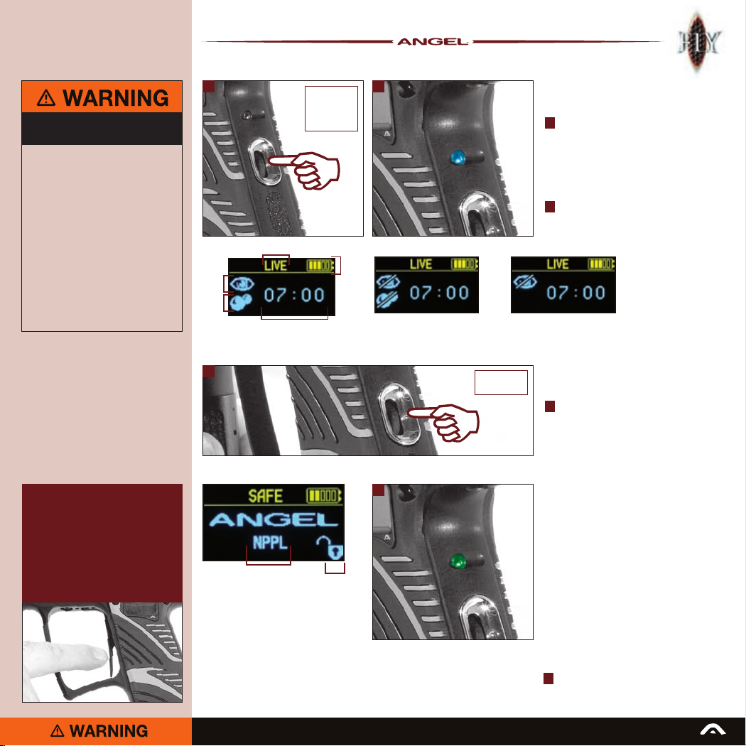
ANGEL is LIVE and capable of ring.
·
Ensure a barrel blocking device is fitted
·
to the ANGEL.
Ensure the hopper is removed from
·
the ANGEL.
Ensure that there are no paintballs
·
in the ANGEL.
Paintball industry standard eye/face/ear
·
and head protection designed specifically
to stop paintballs and meeting ASTM
standard F1776 (USA) or CE standard
(Europe) must be worn by user and any
person within range.
SHOULD YOU BE UNSURE AT ANY STAGE
·
YOU MUST SEEK EXPERT ADVICE.
IMPORTANT NOTE
• When accessing the status menu from
the LIVE screen the ANGEL will remain
LIVE and any trigger pull will return you
to the LIVE screen.
• If accessing any of the other menus
from the status menu, the ANGEL will
revert to SAFE and any trigger pull will
return you to the SAFE screen.
1 2
Gun status
Eyes
status
Ball
status
Game timer status
Screen shows Eyes on and
ball detected
3
Mode
Push & hold
navigation
button for
up to 2 secs
Tournament
lock status
Battery
status
Screen shows Eyes
are faulty.
4
Push & hold
for 2 secs
Switching on
your ANGEL
1 To switch the ANGEL ON press and hold
the navigation button inwards for up to
2 seconds. The ANGEL will turn ON and
will automatically go into LIVE mode
with the eyes on. The display screen will
illuminate and will show the firing status
of the ANGEL.
The LED on the rear of the grip frame will
2
show blue.
Screen shows Eyes are off.
Turning off
your ANGEL
3 Switch the ANGEL OFF by pressing
and holding the navigation button
for 2 seconds. A goodbye message
will be displayed on the screen and
the ANGEL will power down.
Making your ANGEL
safe
When you turn the ANGEL ON, the ANGEL
is LIVE. To make the ANGEL SAFE, either:
• Access the menu options by pushing
the navigation button up or down and
holding for 2 secs. The ANGEL is still
LIVE and capable of ring.
• Choose SAFE from the menu options.
When the ANGEL is SAFE a screen similar
to that on the left will show. The screen will
indicate the ANGEL is SAFE. The screen
will also indicate the mode you are in and
whether the tournament lock is on or off.
The LED on the rear of the grip frame will
4
show green.
READ ALL WARNINGS BEFORE ATTEMPTING ANY WORK ON YOUR ANGEL. SHOULD YOU BE UNSURE AT ANY STAGE YOU MUST SEEK EXPERT ADVICE.
Page 4

4
Navigation Button
1 The functions, features and settings
of the ANGEL are controlled by a
3 directional navigation button
located on the rear of the grip frame.
2 The button can move up and down
to scroll through features and
settings indicated on the display
and can be pressed in to select
the highlighted function or setting
required.
Battery Replacement
3 Remove the right hand grip cheek
by removing the 3 screws using a
suitable 2mm Allen wrench.
4 Using a blunt pick or the 2mm Allen
wrench, carefully prise the battery
clear of its terminals.
5 Remove the battery.
Observe the battery polarity as marked
on the battery housing terminal and on
the battery.
Always use a good quality fresh battery.
1 2
3
5
4
The navigation button is located on the
rear of the grip frame and allows access
to the ANGEL internal menu option.
Push the button up or down and hold
for 2 seconds.
To navigate through the options simply
push the button up to scroll up and
push the button down to scroll down.
Press the button inwards to make
a selection.
ADHERE STRICTLY TO THESE
AND ALL OTHER SAFETY
INSTRUCTIONS AND GUIDELINES
Ensure a barrel blocking device is fitted
·
to the ANGEL.
Ensure the hopper is removed from
·
the ANGEL.
Ensure that there are no paintballs
·
in the ANGEL.
Paintball industry standard eye/face/ear
·
and head protection designed specifically
to stop paintballs and meeting ASTM
standard F1776 (USA) or CE standard
(Europe) must be worn by user and any
person within range.
SHOULD YOU BE UNSURE AT ANY STAGE
·
YOU MUST SEEK EXPERT ADVICE.
READ ALL WARNINGS BEFORE ATTEMPTING ANY WORK ON YOUR ANGEL. SHOULD YOU BE UNSURE AT ANY STAGE YOU MUST SEEK EXPERT ADVICE.
Page 5
Screen shows Eyes off.
5
ADHERE STRICTLY TO THESE
AND ALL OTHER SAFETY
INSTRUCTIONS AND GUIDELINES
ANGEL is LIVE and capable of ring.
·
Ensure a barrel blocking device is fitted
·
to the ANGEL.
Ensure the hopper is removed from
·
the ANGEL.
Ensure that there are no paintballs
·
in the ANGEL.
Paintball industry standard eye/face/ear
·
and head protection designed specifically
to stop paintballs and meeting ASTM
standard F1776 (USA) or CE standard
(Europe) must be worn by user and any
person within range.
SHOULD YOU BE UNSURE AT ANY STAGE
·
YOU MUST SEEK EXPERT ADVICE.
Push & hold
for 2 secs
3
Pull back collet
To remove
5
To attach
21
Screen shows Eyes off.
4
IMPORTANT NOTE:
Please make sure that the Macro line
is trimmed back before re-insertion
after it has been removed.
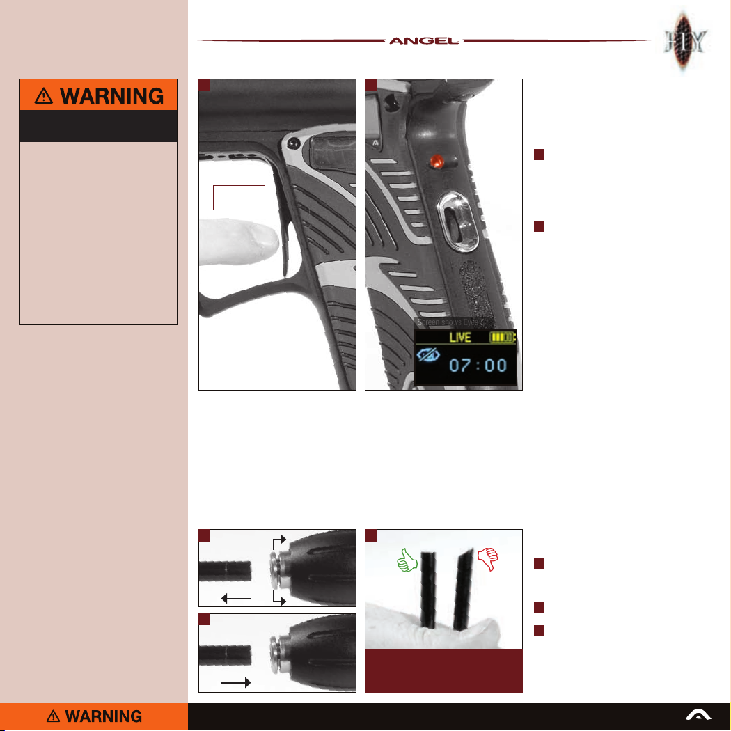
Switching ANGEL eyes
on/off
• Ensure that the ANGEL is on (see page 3).
• As default the ANGEL eyes will always be
ON whenever the ANGEL is switched ON.
The ANGEL eyes can be switched off
1
by pulling and holding the trigger for
2 seconds. The ANGEL’s MROF will drop
to its default MROF eyes off setting. It will
fire 1 shot to confirm that the eyes have
been switched off and the buzzer will
sound once.
The eyes off symbol will be displayed on
2
the display screen. The LED on the rear
of the grip frame will show red.
• To turn the ANGEL eyes back on pull and
hold the trigger again for 2 seconds.
The MROF will return to MROF eyes on
setting (see page 10 for factory default
setting), the buzzer will sound twice and
the eyes on symbol will be displayed on
the display screen. The LED on the rear
of the grip frame will show blue.
• Should the eyes detect a malfunction
due to a component failure or the eyes
becoming dirty they will automatically turn
themselves off and the MROF will revert
to its MROF eyes off setting (see page 10
for factory default setting), the display will
indicate that the eyes are off and that a ball
is not detected.
OPTO board
The ANGEL incorporates the OPTO board.
This board is the latest development in trigger
sensing function. It achieves unsurpassed
advancements in trigger repeatability and
sensitivity, its friction-free non-mechanical
operating button results in faster, shorter
and lighter trigger strokes that give the user
higher prolonged achievable rates of fire.
Macro line hose
3 Pull back the collet on the connector
and keep the collet depressed and pull
the Macro line hose out of the connector
firmly.
Cut back the Macro line hose cleanly
4
and squarely.
Push the hose rmly into the Macro line
5
connector to re-attach.
READ ALL WARNINGS BEFORE ATTEMPTING ANY WORK ON YOUR ANGEL. SHOULD YOU BE UNSURE AT ANY STAGE YOU MUST SEEK EXPERT ADVICE.
Page 6
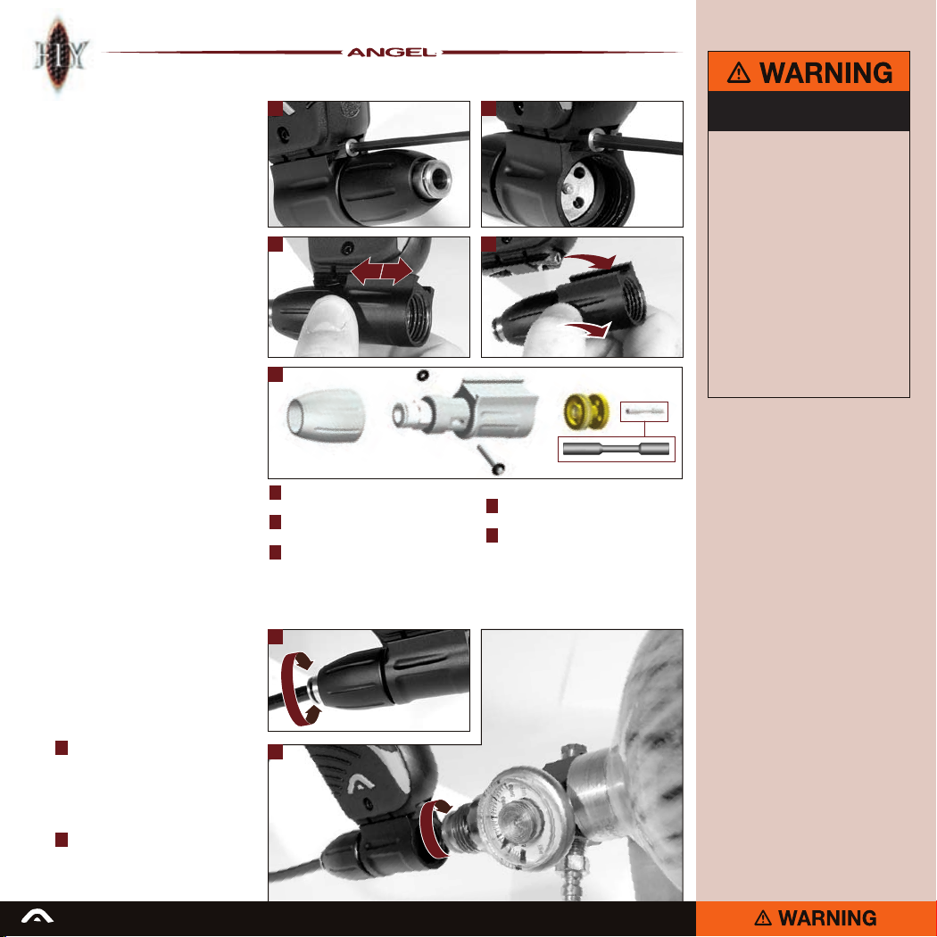
6
Propellant
air/nitrogen supply
The ANGEL is designed to operate on Air/
Nitrogen gas. This needs to be supplied to
the ANGEL using a suitable rst stage
regulator. The ideal input pressure is 450 psi,
but the ANGEL will operate with an
input pressure up to 850 psi.
Note: Some preset systems will deliver
a higher pressure than their rating. So, if
you are using a High Pressure system rated
at 850 psi this could lead you to inputting
more pressure into the ANGEL than is
recommended.
Adjusting or
removing the ASA
on its mounting rail
The ASA connects to the grip frame of the
ANGEL via an integrated dovetail mounting
rail that allows the user to slide the ASA
body along the rail to fine tune the mounting
position or remove the ASA completely.
The ASA body is locked down onto the
rail via two set screws located within
a central recess at the front and back
of the integrated rail.
Installing an
air/nitrogen system
Each ANGEL comes complete with a centrally
ported on/off ANGEL ASA allowing for the
easy connection of a preset air/nitrogen
system for immediate use.
6 Before installing your preset system into
the ASA always ensure that the on/off
adjuster knob is wound out approximately
halfway. Be careful not to unscrew the
ASA on/off adjuster knob too far as it
is possible to completely disassemble
the ASA.
7 To install your air or nitrogen system
screw your tank and regulator onto the
ASA and tighten.
1 2
3 4
5
1 Using a 3mm Allen wrench remove the
screw at the front of the ASA.
Using a 3mm Allen wrench remove the
2
screw at the rear of the ASA.
3 Slide the ASA forward or backward to
the desired position.
6
7
Depression
Pin
Note: Pin orientation
OR
4 Slide the ASA clear of the mounting
bracket to remove completely.
5 When disassembling the ASA note the
orientation of the ‘depression pin’
ADHERE STRICTLY TO THESE
AND ALL OTHER SAFETY
INSTRUCTIONS AND GUIDELINES
Always follow instructions, warnings
·
and guidelines given with any first stage
regulator you use with the ANGEL.
Use compressed air/nitrogen gas only
·
DO NOT USE CO2.
Only use a paintball regulator that has
·
been designed for air or nitrogen gas.
Do not exceed 850 psi (58bar) input
·
pressure to the ANGEL.
Take suitable precautions when using
·
sharp cutting instruments.
The Macro Line hose must be cut back
·
cleanly and square prior to attachment
or re-attachment to ensure secure fitment.
SHOULD YOU BE UNSURE AT ANY STAGE
·
YOU MUST SEEK EXPERT ADVICE.
READ ALL WARNINGS BEFORE ATTEMPTING ANY WORK ON YOUR ANGEL. SHOULD YOU BE UNSURE AT ANY STAGE YOU MUST SEEK EXPERT ADVICE.
Page 7
7
ADHERE STRICTLY TO THESE
AND ALL OTHER SAFETY
INSTRUCTIONS AND GUIDELINES
Ensure a barrel blocking device is fitted to
·
the ANGEL.
Ensure the hopper is removed from the
·
ANGEL.
Ensure that there are no paintballs in the
·
ANGEL.
Ensure the ANGEL is switched off via
·
the navigation button on the rear of the
grip frame prior to fitting your first stage
regulator.
Paintball industry standard eye/face/ear
·
and head protection designed specifically
to stop paintballs and meeting ASTM
standard F1776 (USA) or CE standard
(Europe) must be worn by user and any
person within range.
Always follow instructions, warnings
·
and guidelines given with any first stage
regulator you use with the ANGEL.
Use compressed air/nitrogen gas only
·
DO NOT USE CO2.
Only use a paintball regulator that has
·
been designed for air or nitrogen gas.
Do not exceed 850 psi (58 bar) input
·
pressure to the ANGEL.
Take suitable precautions when using
·
sharp cutting instruments.
The Macro Line hose must be cut back
·
cleanly and square prior to attachment
or re-attachment to ensure secure fit.
SHOULD YOU BE UNSURE AT ANY STAGE
·
YOU MUST SEEK EXPERT ADVICE.
1 2
3
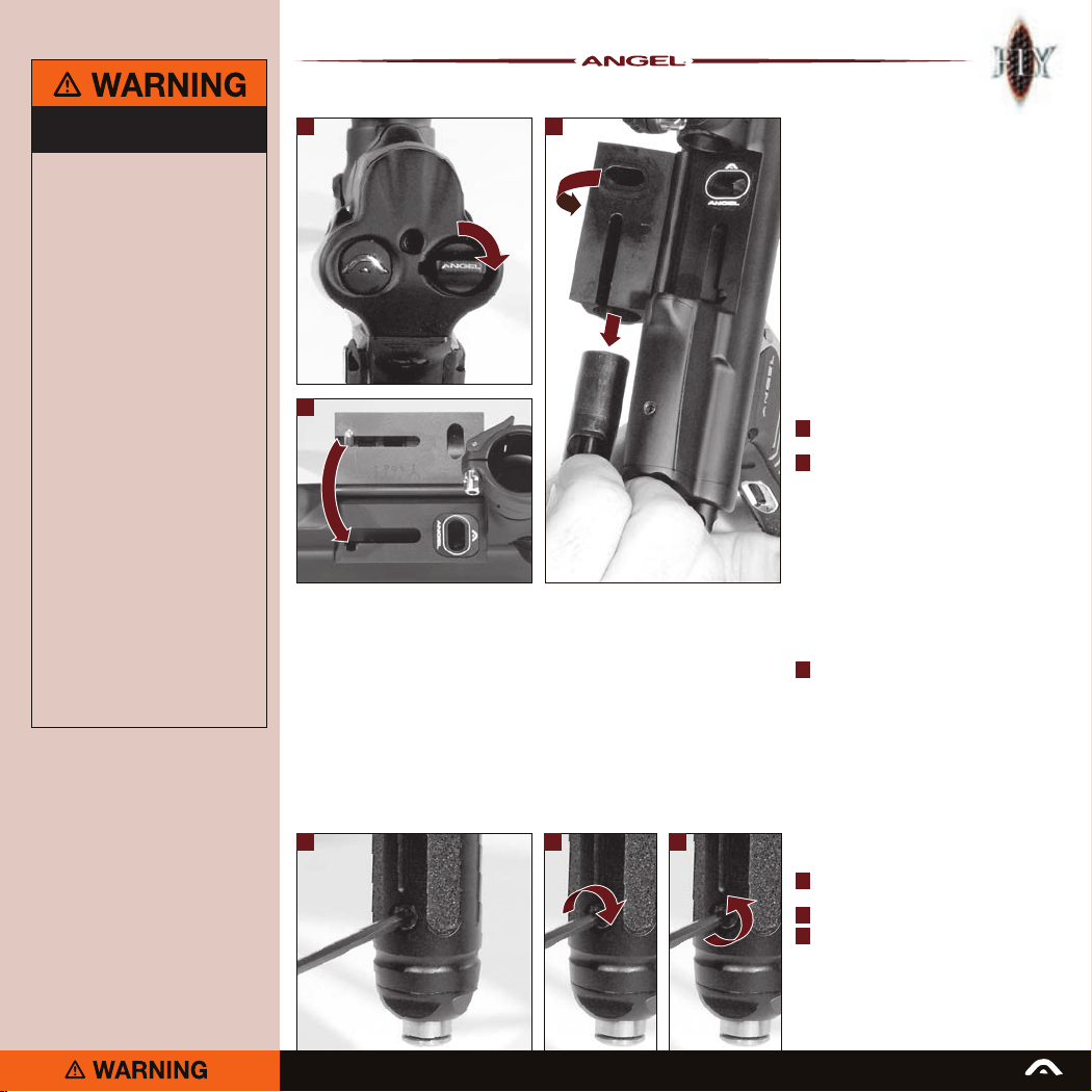
Bolt removal
The ANGEL’s bolt includes 2 gas ports that
direct a small proportion of air onto the
lenses of the ANGEL eye sensors, which
negates the need to clean them as regularly
as other high end markers. If you experience
a serious breakage in the breech during a
game your ANGEL eyes will switch off and
under most circumstances you will be able to
continue firing paint and the gas from the bolt
ports will clean your ANGEL eyes. You can
then switch them back on by holding down
the trigger for 2 seconds.
Note: It is important that the bolt is
kept clean and free from dirt or grit and
that it is run dry with no lubricant. We
recommend that you clean your bolt after
each day of use.
Turn the breech release knob clockwise
1
about a quarter of a turn.
Lift and rotate the breech block as
2
illustrated. Using the bolt pin slide
the bolt from the breech.
Note: If the breech will not open it may
be the case that the bolt is in the forward
position. To check this look down the feed
tube. If you can see the bolt, the breech
will not open. Push the bolt back into the
marker as far as it will go - the breech
should now open.
Note: To replace the bolt reverse these
instructions.
Note that the bolt pin must locate in
3
the correct place to enable the breech
to close.
CAUTION: The ANGEL must not be red
without a bolt present. This can result in
damage to your ANGEL. Any damage caused
from failure to follow these instructions is not
covered by your ANGEL warranty.
54
READ ALL WARNINGS BEFORE ATTEMPTING ANY WORK ON YOUR ANGEL. SHOULD YOU BE UNSURE AT ANY STAGE YOU MUST SEEK EXPERT ADVICE.
6
Velocity Adjustment
4 Using a 3mm Allen wrench turn the
velocity adjuster screw either;
clockwise to decrease velocity
5
counter-clockwise to increase velocity.
6
Page 8
8
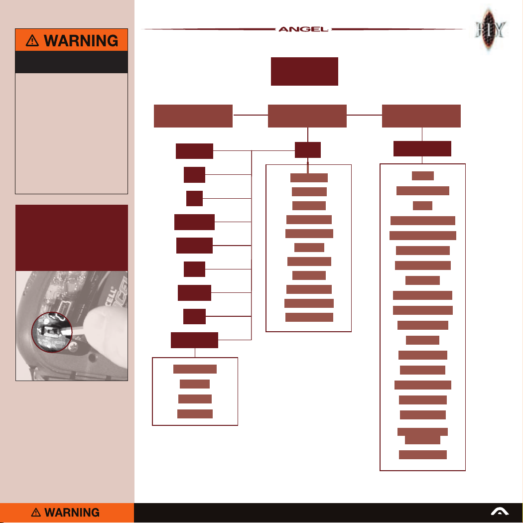
OLED menu
Status
The Status menu allows you to select
between Live/Safe, the Information display
screen and the Parameters setting.
• To access the Status menu press and
hold the navigation button up or down
for 2 seconds.
Note: If a trigger pull has been made
immediately prior to pressing the
navigation button then a further 5
second delay will be initiated to prevent
accidentally putting the ANGEL in SAFE
during a game situation.
• Once in the Status menu use the
navigation button to scroll up or down
to choose between Live/Safe, Information
and Parameters.
• Pressing the navigation button inwards
will select the highlighted function.
Information
The Information screen will display all
the relevant information relating to the
electronic settings of your ANGEL.
• With the ANGEL on and Live push the
navigation button up or down for 2
seconds.
• The ANGEL will be in the Status menu.
• Use the navigation button to scroll through
the Status menu settings until
Information is highlighted.
• Push the navigation button inwards to
select the Information menu.
• The following information will be displayed
on the OLED. Scroll up or down using the
navigation button to view this information.
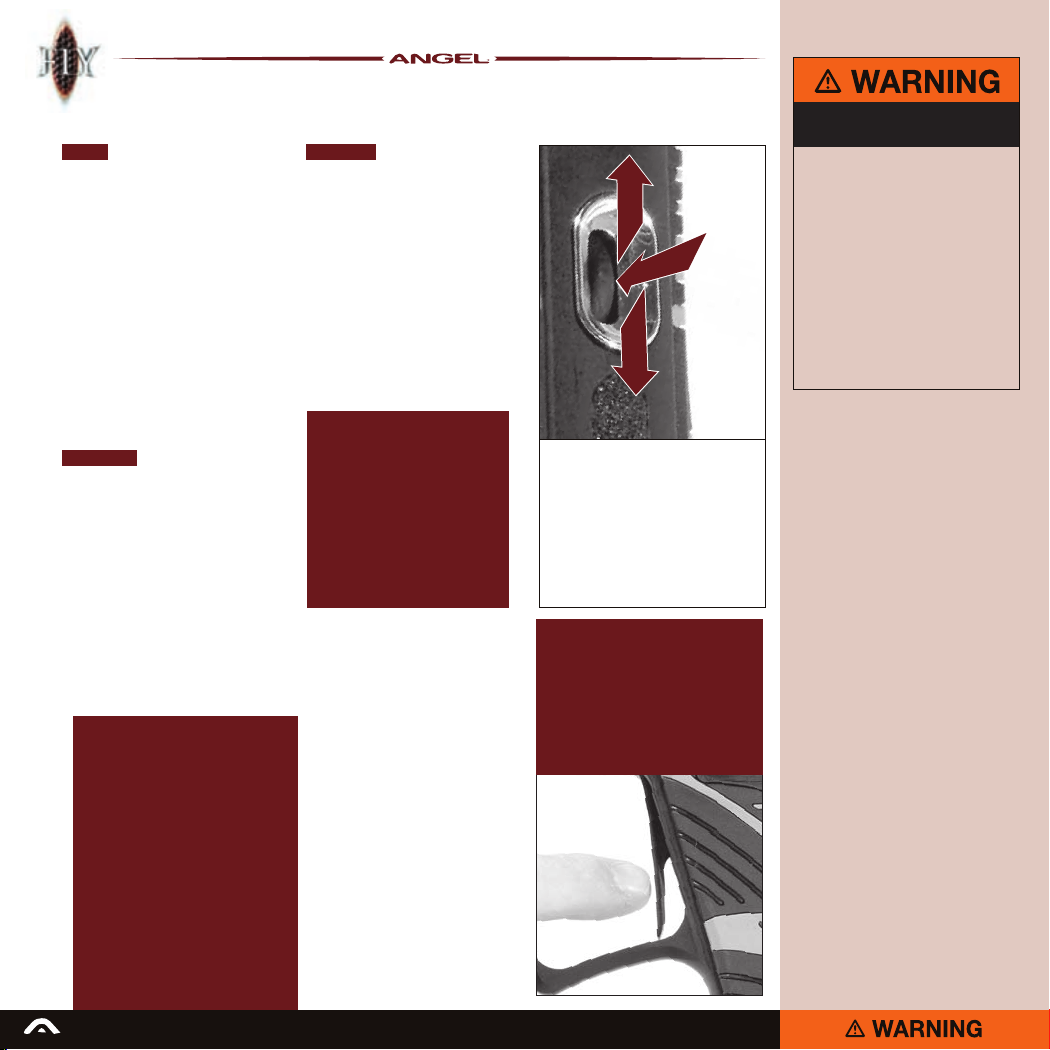
Status
Software version
Mode
Soft breakout setting
Hard breakout setting
Soft ramp setting
Hard ramp setting
Dwell time
MROF eyes on limit
MROF eyes off limit
De-bounce level
Paint Type
Shot % filtering
Anti Bolt Stick
ANGEL eyes on/off
Game timer set
Alarm time set
Total shots fired since reset
READ ALL WARNINGS BEFORE ATTEMPTING ANY WORK ON YOUR ANGEL. SHOULD YOU BE UNSURE AT ANY STAGE YOU MUST SEEK EXPERT ADVICE.
Parameters
The ANGEL’s settings can be easily adjusted
from the Parameters menu.
• With the ANGEL on and Live push and
hold the navigation button up or down for
2 seconds.
• The ANGEL will be in the Status menu.
• Use the navigation button to scroll
through the Status menu settings until
Parameters is highlighted.
• Push the navigation button inwards to
select the Parameters menu.
The following functions are all accessible
via the navigation button and can all
be accessed and adjusted from the
Parameters display.
Modes
Valve Dwell
De-bounce
Paint Type
MROF eyes ON
MROF eyes OFF
Breakout
Ramp feature
Shot Filter
ABS
Game Timer Set
Alarm Time Set
The navigation button is located on the
rear of the grip frame and allows access
to the internal menu option.
Push the button up or down and hold for
2 seconds.
To navigate through the options simply
push the button up to scroll up and push
the button down to scroll down. Press the
button inwards to make a selection.
IMPORTANT NOTE
When accessing the status menu from
the LIVE screen the ANGEL will remain
LIVE and any trigger pull will return you
to the LIVE screen.
If accessing any of the other menus from
the status menu, the ANGEL will revert to
SAFE and any trigger pull will return you
to the SAFE screen.
ADHERE STRICTLY TO THESE
AND ALL OTHER SAFETY
INSTRUCTIONS AND GUIDELINES
Ensure a barrel blocking device is fitted
·
to the ANGEL.
Ensure the hopper is removed from
·
the ANGEL.
Ensure that there are no paintballs
·
in the ANGEL.
Paintball industry standard eye/face/ear
·
and head protection designed specifically
to stop paintballs and meeting ASTM
standard F1776 (USA) or CE standard
(Europe) must be worn by user and any
person within range.
SHOULD YOU BE UNSURE AT ANY STAGE
·
YOU MUST SEEK EXPERT ADVICE.
Page 9
ADHERE STRICTLY TO THESE
AND ALL OTHER SAFETY
INSTRUCTIONS AND GUIDELINES
Ensure a barrel blocking device is fitted
·
to the ANGEL.
Ensure the hopper is removed from
·
the ANGEL.
Ensure that there are no paintballs
·
in the ANGEL.
Paintball industry standard eye/face/ear
·
and head protection designed specifically
to stop paintballs and meeting ASTM
standard F1776 (USA) or CE standard
(Europe) must be worn by user and any
person within range.
SHOULD YOU BE UNSURE AT ANY STAGE
·
YOU MUST SEEK EXPERT ADVICE.
IMPORTANT NOTE:
Tournament lock
To comply with some Tournament
rules some of the ANGEL’s features are
required to be locked down so that they
cannot be adjusted on the field of play.
For more details see page 14.
Semi Auto
NPPL
PSP
Millennium
XBall/NXL
CFOA
Full Auto
Demo
Custom Semi
Soft Breakout
Breakout
Soft Ramp
Hard Ramp
STATUS
ParametersLive/Safe Information
Modes
Valve Dwell
De-bounce
Paint Type
MROF eyes ON
MROF eyes OFF
Breakout
Ramp Feature
Shot Filter
Anti Bolt Stick
Game Timer Set
Alarm Time Set
Current Settings
Status
Software version
Mode
Soft breakout setting
Hard breakout setting
Soft ramp setting
Hard ramp setting
Dwell time
MROF eyes on limit
MROF eyes off limit
De-Bounce level
Paint Type
Shot % filtering
Anti Bolt Stick
ANGEL eyes on/off
Game timer set
Alarm time set
Total shots fired
since reset
Battery voltage
9
READ ALL WARNINGS BEFORE ATTEMPTING ANY WORK ON YOUR ANGEL. SHOULD YOU BE UNSURE AT ANY STAGE YOU MUST SEEK EXPERT ADVICE.
Page 10
10
MODES
• Ensure that the ANGEL is switched on.
• Ensure that you are not activating the
trigger.
• Push and hold the navigation button
UP or DOWN for 2 seconds.
• The Status menu will be displayed.
• Push the navigation button up to highlight
the Parameters menu.
• Push the navigation button in to select
the Parameters menu.
• From the Parameters menu, select the
Mode feature by pushing the navigation
button inward.
• Scroll up or down through the Mode
options by pushing the navigation button
up or down.
• Once the desired Mode setting has been
reached, press the navigation button
inwards to save the new setting.
• A Saved Mode message will be
displayed.
The Parameters menu will be displayed.
Semi Auto
The ANGEL eyes will default to on
whenever the ANGEL is made live via the
navigation button.
With the eyes activated, the ANGEL will
only fire when a paintball is present and
has been detected by the ANGEL eyes.
With the eyes activated, the MROF that the
ANGEL will re at is limited by the MROF
eyes on level.
With the eyes turned off, the MROF that the
ANGEL will re at is limited by the MROF
eyes off level.
The ANGEL will re 1 shot for each pull
of the trigger.
Breakout and Ramp settings do not
function in this Mode.
NPPL
The ANGEL eyes will default to on
whenever the ANGEL is made live via
the navigation button.
With the eyes activated, the ANGEL will
only fire when a paintball is present and
has been detected by the ANGEL eyes.
With the eyes activated, the MROF that
the ANGEL will re at is limited by the
MROF eyes on level.
READ ALL WARNINGS BEFORE ATTEMPTING ANY WORK ON YOUR ANGEL. SHOULD YOU BE UNSURE AT ANY STAGE YOU MUST SEEK EXPERT ADVICE.
With the eyes turned off, the MROF that
the ANGEL will re at is limited by the
MROF eyes off level.
The ANGEL will re 1 shot for each pull
of the trigger.
Breakout and Ramp settings do not
function in this Mode.
PSP
The ANGEL eyes will default to on
whenever the ANGEL is made live via the
navigation button.
With the eyes activated, the ANGEL will
only fire when a paintball is present and
has been detected by the ANGEL eyes.
The rst 3 shots will be red in semi
automatic.
On the 4th shot the ANGEL will ramp to a
preset MROF set at 15.4 balls per second,
provided that the user maintains trigger
pulls at a rate of 5 balls per second or
above.
If the user stops firing for more than
1 second, the initial 3 shots in semi
automatic must be re-initiated.
Breakout and Ramp settings do not
function in this Mode.
Millennium
The ANGEL eyes will default to on
whenever the ANGEL is made live via the
navigation button.
With the eyes activated, the ANGEL will
only fire when a paintball is present and
has been detected by the ANGEL eyes.
The rate of fire will be capped at 15 shots
per second.
Ramping of shots is allowed once 8 balls
per second (BPS) is achieved the ANGEL
may ramp up to 15 BPS only if 8 BPS or
greater is maintained. Once the trigger is
released, only 1 additional shot may be
discharged.
Breakout and Ramp settings do not
function in this Mode.
XBall/NXL
The ANGEL eyes will default to on
whenever the ANGEL is made live via
the navigation button.
With the eyes activated the ANGEL will only
fire when a paintball is present and has
been detected by the ANGEL eyes.
The rst 3 shots will be red in semi
automatic.
On the 4th shot if the trigger is pulled and
held the ANGEL will re fully automatic upto
a preset maximum MROF set at 15.4 BPS.
The ANGEL will stop ring as soon
as the trigger is released.
If the user stops firing for more than
1 second, the initial 3 shots in semi
automatic must be re-initiated.
Breakout and Ramp settings do not
function in this Mode.
CFOA
The ANGEL eyes will default to on
whenever the ANGEL is made live via
the navigation button.
With the eyes activated, the ANGEL will
only fire when a paintball is present and
has been detected by the ANGEL eyes.
The rst 3 shots will be red in semi
automatic.
On the 4th shot the ANGEL will ramp
to a preset MROF set at 15.4 balls per
second, provided that the user maintains
trigger pulls at a rate at 5 balls per second
or above.
If the user stops firing for more than
1 second, the initial 3 shots in semi
automatic must be re-initiated.
Breakout and Ramp settings do not
function in this Mode.
Full Auto
The ANGEL eyes will default to on
whenever the ANGEL is made live via the
navigation button.
With the eyes activated, the ANGEL will
only fire when a paintball is present and
has been detected by the ANGEL eyes.
The ANGEL will re at a capped maximum
rate of 15 balls per second with the ANGEL
eyes activated.
With the angel eyes deactivated, the ANGEL
will fire at a capped maximum rate of 15
balls per second.
It is possible to lower the MROF with both
eyes on and eyes off in this mode, but you
will not be permitted to raise them above
the 15 BPS cap.
Breakout and Ramp settings do not
function in this Mode.
Demo
This is a dry firing mode for firing the
ANGEL when on display and is designed
to demonstrate the rate of fire achievable.
It should only be used for demonstration
ADHERE STRICTLY TO THESE
AND ALL OTHER SAFETY
INSTRUCTIONS AND GUIDELINES
Ensure a barrel blocking device is fitted
·
to the ANGEL.
Ensure the hopper is removed from
·
the ANGEL.
Ensure that there are no paintballs
·
in the ANGEL.
Paintball industry standard eye/face/ear
·
and head protection designed specifically
to stop paintballs and meeting ASTM
standard F1776 (USA) or CE standard
(Europe) must be worn by user and any
person within range.
SHOULD YOU BE UNSURE AT ANY STAGE
·
YOU MUST SEEK EXPERT ADVICE.
The ANGEL’s default values are :
Mode semi
Soft breakout settings : seconds 10
Hard breakout settings: seconds 10
Soft ramp settings: start delay (shots) 4
Kick in (BPS) 5
Drop out (BPS) 4
Hard ramp settings: start delay (shots) 4
Kick in (BPS) 5
Drop out (BPS) 4
Dwell time (m/secs) 9
MROF eyes ON limit unlimited
MROF eyes OFF limit 15bps
De-Bounce (level) 10
Paint Type 8
Shot % Filter 5%
ABS (Anti bolt stick) [m/secs] 0.25
ANGEL eyes ON
Game time set (mins/ Secs) 7:10
Alarm time set (mins/secs) 1:00
Page 11
11
ADHERE STRICTLY TO THESE
AND ALL OTHER SAFETY
INSTRUCTIONS AND GUIDELINES
Ensure a barrel blocking device is fitted
·
to the ANGEL.
Ensure the hopper is removed from
·
the ANGEL.
Ensure that there are no paintballs
·
in the ANGEL.
Paintball industry standard eye/face/ear
·
and head protection designed specifically
to stop paintballs and meeting ASTM
standard F1776 (USA) or CE standard
(Europe) must be worn by user and any
person within range.
SHOULD YOU BE UNSURE AT ANY STAGE
·
YOU MUST SEEK EXPERT ADVICE.
purposes, as the ANGEL eyes feature is
reverse functioned so that it cannot fire
should a paintball be detected.
Breakout and Ramp settings do not
function in this Mode.
Custom Semi
The ANGEL eyes will default to on
whenever the ANGEL is made live via the
navigation button.
With the eyes activated, the ANGEL will
only fire when a paintball is present and
has been detected by the ANGEL eyes.
With the eyes activated, the MROF that the
ANGEL will re at is limited by the MROF
eyes on level.
With the eyes turned off, the MROF that the
ANGEL will re at is limited by the MROF
eyes off level.
The ANGEL will re 1 shot for each pull of
the trigger.
Breakout and Ramp settings can be used
individually or in combination in this Mode.
Breakout
There are 2 breakout modes that can only
be used when the ANGEL is in custom
semi mode.
Soft breakout
Once the soft breakout feature has been
selected from the custom modes screen
and the ANGEL is on and live. It will re as
if it were in normal semi auto mode until
the breakout mode is activated.
To activate the breakout feature press the
navigation button inwards. The alarm will
momentarily sound to indicate that the
breakout mode has been initiated. In order
for the ANGEL to start ring in the breakout
mode once it has been initiated, a rate of
trigger pulls higher than 4 per second must
be reached and maintained within the time
period that the breakout mode is active.
The duration of the time period that the
breakout mode is active can be adjusted.
The range for this adjustment is 1 – 20
seconds. If the rate of trigger pulls at any
point once the breakout mode has been
initiated falls below 4 per second, or should
the trigger be pulled and held in for 2 secs
or the time period of the breakout elapses,
the breakout mode will revert to the
previously selected mode.
Hard breakout
Once the hard breakout feature has been
selected from the custom modes screen
and the ANGEL is on and live, it will re as
if it were in normal semi auto mode until
the breakout mode is activated.
To activate the breakout feature press the
navigation button inwards. The alarm will
momentarily sound to indicate that the
breakout mode has been initiated. In order
for the ANGEL to start ring in the breakout
mode once it has been initiated, the trigger
must be pulled and held in within the time
period that the breakout mode is active.
The duration of the time period that the
breakout mode is active can be adjusted.
The range for this adjustment is 1 to 20
seconds. If the trigger is released at any
point once the breakout mode has been
initiated, or the time period of the breakout
elapses, the breakout mode will revert
to the previously selected mode.
Ramp
There are 2 Ramp modes that can only be
used when the ANGEL is in custom semi
mode: Soft ramp and Hard ramp.
There are 3 Parameters that can be
adjusted to custom tune the ramp modes.
Start delay: This is the number of shots
fired before the ramp mode starts.
The range for the start delay is between
1 and 20 shots.
Kick in point: This sets the minimum
number of trigger pulls per second that
must be reached in order for the software
to add shots. The range for the kick in
point is between 4 and 16 trigger pulls
per second.
Drop out point: This sets the minimum
number of trigger pulls per second that
must be maintained in order for the
software to add shots. The range for the
drop out point is between 4 and 16 trigger
pulls per second. Should the number of
trigger pulls drop below this rate for more
than 1 second the software will no longer
add shots until the kick in point has been
re-achieved.
To enable any of the ramping features it
must be selected from the custom modes
menu.
Parameters
Valve dwell
Dwell controls the valve opening time.
Longer dwell uses more gas and generates
variable pressures. Shorter dwell uses less
gas and reduces noise, but is less tolerant
of poor quality paint and can result in
weak shots. The range of adjustment that
is available is from 6 milliseconds to 15
milliseconds in 0.5 millisecond increments.
Important Note:
The internal lock button must be used
to turn Dwell options on or off.
• Ensure that the ANGEL is switched on
• Ensure that you are not activating the
trigger
• Push and hold the navigation button UP
or DOWN for 2 seconds
• The Status menu will be displayed
• Push the navigation button up to highlight
the Parameters menu
• Push the navigation button in to select
the Parameters menu
• From the Parameters menu select the
Dwell feature by pushing the navigation
button inwards.
• Scroll up or down through the Dwell
settings by pushing the navigation button
up or down.
• Once the desired setting has been
reached, press the navigation button
inwards to save the new setting.
• A Saved Dwell message will be
displayed.
The Parameters menu will be displayed.
De-Bounce
This is the length of time that the trigger
has to be pulled for it to be accepted by
the electronics as a valid trigger activation.
There are 20 levels of adjustment, 1 being
the least sensitive and 20 the most
sensitive adjustment.
• Ensure that the ANGEL is switched on.
• Ensure that you are not activating the
trigger.
• Push and hold the navigation button UP
or DOWN for 2 seconds.
• The Status menu will be displayed.
READ ALL WARNINGS BEFORE ATTEMPTING ANY WORK ON YOUR ANGEL. SHOULD YOU BE UNSURE AT ANY STAGE YOU MUST SEEK EXPERT ADVICE.
Page 12
12
Parameters cont...
De-Bounce cont...
• Push the navigation button up to highlight
the Parameters menu.
• From the Parameters menu select the
De-Bounce feature by pushing the
navigation button inwards.
• Scroll up or down through the
De-Bounce settings by pushing the
navigation button up or down.
• Once the desired setting is reached press
the navigation button inwards to save the
new setting.
A Saved De-Bounce message will be
displayed.
The Parameters menu will be displayed.
Paint Type
This allows you to select the correct ANGEL
eye settings for the type of paint that you
are using.
Once you have selected the correct setting
the ANGEL eyes program will intelligently
adjust itself to the fragility of your paint.
1 - 6 = Fragile
7 - 10 = Medium
11 - 12 = Hard
• Ensure that your loader is at its maximum
performance and reliability otherwise you
may encounter problems related
to the loader.
• Selection of a paint type setting that
is too high may result in ball breakages.
• Ensure that the ANGEL is switched on.
• Ensure that you are not activating the
trigger.
• Push and hold the navigation button
UP or DOWN for 2 seconds.
• The Status menu will be displayed.
• Push the navigation button up to highlight
the Parameters menu.
• Push the navigation button in to select
the Parameters menu.
• From the Parameters menu select the
Paint Type feature by pushing the
navigation button inwards.
• Scroll up or down through the Paint
Type settings by pushing the navigation
button up or down.
Once the desired setting has been reached
press the navigation button inwards to save
the new setting.
A Saved Paint Type message will be
displayed.
The Parameters menu will be displayed.
MROF eyes on
This allows the user to set the Maximum
Rate of Fire whilst the ANGEL eyes are on.
There are 20 levels of adjustment ranging
from 10 to unlimited balls per second.
• Ensure that the ANGEL is switched on.
• Ensure that you are not activating the
trigger.
• Push and hold the navigation button UP
or DOWN for 2 seconds.
• The Status menu will be displayed.
• Push the navigation button up to highlight
the Parameters menu.
• Push the navigation button in to select
the Parameters menu.
• From the Parameters menu select the
MROF eyes on feature by pushing the
navigation button inwards.
• Scroll up or down through the MROF
eyes on settings by pushing the
navigation button up or down.
• Once the desired setting has been
reached press the navigation button
inwards to save new setting.
A Saved MROF eyes on message will be
displayed.
The Parameters menu will be displayed.
MROF eyes off
This allows the user to set the Maximum
Rate Of Fire whilst the ANGEL eyes are off.
There are 20 levels of adjustment ranging
from 10 to unlimited balls per second.
• Ensure that the ANGEL is switched on.
• Ensure that you are not activating the
trigger.
• Push and hold the navigation button UP
or DOWN for 2 seconds.
• The Status menu will be displayed.
• Push the navigation button up to highlight
the Parameters menu.
• Push the navigation button in to select
the Parameters menu.
• From the Parameters menu select the
MROF eyes off feature by pushing the
navigation button inwards.
• Scroll up or down through the MROF
eyes off settings by pushing the
navigation button up or down.
• Once the desired setting has been
reached press the navigation button
inwards to save the new setting.
A Saved MROF eyes off message will
be displayed.
The Parameters menu will be displayed.
Breakout
This allows the user to select between
a soft and hard breakout mode. Once the
hard or soft option has been selected, the
duration that the breakout will be active
for can then be selected. The length of the
breakout mode duration can be set from
1 to 20 seconds.
• Ensure that the ANGEL is switched on.
• Ensure that you are not activating the
trigger.
• Push and hold the navigation button UP
or DOWN for 2 seconds.
• The Status menu will be displayed.
• Push the navigation button up to highlight
the Parameters menu.
• Push the navigation button in to select
the Parameters menu.
• From the Parameters menu select the
Breakout feature by pushing the
navigation button inwards.
• Select Soft or Hard Breakout option using
the navigation button by pressing
it inwards to confirm the desired option.
• Select the duration that you wish the
breakout to be active for by using the
navigation button to scroll between the
values of 1 and 20 seconds, then press
the navigation button inwards to confirm
your desired settings.
A Saved Soft/Hard Breakout message
is displayed.
The Breakout menu will be displayed.
Ramp
This allows the user to select 2 levels of
ramp mode: Soft Ramp and Hard Ramp.
Once the level of Ramp has been selected,
the user can then customize the ramp
mode by selecting the start delay (number
of shots to be fired before the ramp mode
activates, adjustable between 1 and 20
shots), kick in BPS (number of trigger pulls
per second that has to be reached to get
the ramp mode to start, adjustable between
4 and 16 shots), and the drop out BPS
(minimum number of trigger pulls that must
be maintained in order to keep the ANGEL
in ramp mode, adjustable between 4 and
16 shots).
ADHERE STRICTLY TO THESE
AND ALL OTHER SAFETY
INSTRUCTIONS AND GUIDELINES
Ensure a barrel blocking device is fitted
·
to the ANGEL.
Ensure the hopper is removed from
·
the ANGEL.
Ensure that there are no paintballs
·
in the ANGEL.
Paintball industry standard eye/face/ear
·
and head protection designed specifically
to stop paintballs and meeting ASTM
standard F1776 (USA) or CE standard
(Europe) must be worn by user and any
person within range.
SHOULD YOU BE UNSURE AT ANY STAGE
·
YOU MUST SEEK EXPERT ADVICE.
READ ALL WARNINGS BEFORE ATTEMPTING ANY WORK ON YOUR ANGEL. SHOULD YOU BE UNSURE AT ANY STAGE YOU MUST SEEK EXPERT ADVICE.
Page 13
13
ADHERE STRICTLY TO THESE
AND ALL OTHER SAFETY
INSTRUCTIONS AND GUIDELINES
Ensure a barrel blocking device is fitted
·
to the ANGEL.
Ensure the hopper is removed from
·
the ANGEL.
Ensure that there are no paintballs
·
in the ANGEL.
Paintball industry standard eye/face/ear
·
and head protection designed specifically
to stop paintballs and meeting ASTM
standard F1776 (USA) or CE standard
(Europe) must be worn by user and any
person within range.
SHOULD YOU BE UNSURE AT ANY STAGE
·
YOU MUST SEEK EXPERT ADVICE.
Parameters cont...
Ramp cont...
• Ensure that the ANGEL is switched on.
• Ensure that you are not activating the
trigger.
• Push and hold the navigation button UP
or DOWN for 2 seconds.
• The Status menu will be displayed.
• Push the navigation button up to highlight
the Parameters menu.
• Push the navigation button in to select
the Parameters menu.
• From the Parameters menu select the
Ramp feature by pushing the
navigation button inwards.
• Select Soft or Hard Ramp option using
the navigation button by pressing it
inwards to confirm the desired option.
• You can then select to adjust Start
Delay, Kick in BPS and Drop out
BPS by pressing the navigation button
inwards.
A Saved Start Delay, Kick in BPS and
Drop out BPS message will be displayed.
The Soft or Hard Ramp menu will be
displayed.
Shot % filtering
This allows the adjustment of the point
within the current firing cycle that a new
buffered shot will be accepted.
The Shot % lter is adjustable from
1 to 20 levels.
Level 1 turns the shot filtering off which
allows the additional shot to be registered
at the earliest point after the eyes have
detected a ball and the trigger has provided
a viable re command. Levels 2 through
to 20 sets the % of the ring cycle that
must have been completed before the
additional shot may be allowed from 10%
of the cycle increasing in 5% increments
up to a maximum of 100% of the cycle.
• Ensure that the ANGEL is switched on.
• Ensure that you are not activating the
trigger.
• Push and hold the navigation button
UP or DOWN for 2 seconds.
• The Status menu will be displayed.
• Push the navigation button up to highlight
the Parameters menu.
• Push the navigation button in to select
the Parameters menu.
• From the Parameters menu select the
Shot % Filtering feature by pushing the
navigation button inwards.
• Scroll up or down through the Shot
% Filtering settings by pushing the
navigation button up or down.
• Once the desired setting has been
reached press the navigation button
inwards to save the new setting.
A Saved Shot % Filtering message will
be displayed.
The Parameters menu will be displayed.
Anti Bolt Stick
First shot drop off can occur when the
valve or Ram incurs static friction after a
period of inactivity. This results in the first
shots fired after this inactivity being lower
in velocity because the seals need to break
free from the forces of the static friction.
Anti Bolt Stick programming allows the
dwell time to be increased for the rst 2
shots if the ANGEL has been inactive for 15
seconds to overcome static friction. There
are 20 levels of ABS adjustment ranging
from 0.25 milliseconds to 5 milliseconds.
• Ensure that the ANGEL is switched on.
• Ensure that you are not activating the
trigger.
• Push and hold the navigation button UP
or DOWN for 2 seconds.
• The Status menu will be displayed.
• Push the navigation button up to highlight
the Parameters menu.
• Push the navigation button in to select
the Parameters menu.
• From the Parameters menu select the
Anti Bolt Stick feature by pushing the
navigation button inwards.
• Scroll up or down through the Anti Bolt
Stick settings by pushing the navigation
button up or down.
• Once the desired setting has been
reached, press the navigation button
inwards to save the new setting.
A Saved Anti Bolt Stick message will be
displayed.
The Parameters menu will be displayed.
Software version
The software version is displayed on the
information page.
• With the ANGEL on and Live push the
navigation button up or down for
2 seconds.
• The ANGEL will be in the Status menu.
• Use the navigation button to scroll
through the Status menu settings until
Information is highlighted.
Push the navigation button inwards to
select the Information menu.
Factory reset
The default factory settings can be restored
if required at any time.
• Press the internal button located on
the circuit board inside the grip frame.
• The screen will display the internal
options menu.
• Using the navigation button scroll
up or down to select the reset function.
• Press the navigation button inwards
to initiate the reset function.
• You will be asked to conrm that
you wish to continue with this action.
Press the navigation button inwards
to confirm this is correct.
• A reset message will be displayed on
the screen confirming that the default
settings have successfully been restored.
READ ALL WARNINGS BEFORE ATTEMPTING ANY WORK ON YOUR ANGEL. SHOULD YOU BE UNSURE AT ANY STAGE YOU MUST SEEK EXPERT ADVICE.
Page 14
14
Game timer/alarm
This is a fully interactive game timer with
countdown alarm that will allow you and
your team to play in unison. The timer and
alarm can be set in either 1 second or
1 minute increments from 0 to 60 minutes.
Once the alarm and timer are set they will
be activated by the first trigger pull after
making the ANGEL live and selecting the
timer function.
• Ensure that the ANGEL is switched on.
• Ensure that you are not activating the
trigger.
• Push and hold the navigation button UP
or DOWN for 2 seconds.
• The Status menu will be displayed.
• Push the navigation button up to highlight
the Parameters menu.
• Push the navigation button in to select
the Parameters menu.
• From the Parameters menu select
the Game or alarm timer feature by
pushing the navigation button inwards.
• Using the navigation button, scroll up
or down to highlight Change timer.
• Push the navigation button to select
Change timer.
• Using the navigation button scroll up
or down to select the first digit required.
• Push the navigation button inwards
to store the first digit.
• Repeat the previous two points
to store the 2nd, 3rd and 4th digits.
Saved game timer/game alarm
message displayed on screen.
Tournament lock
To comply with some Tournament rules
some of the ANGEL’s features are required
to be locked down so that they cannot be
adjusted on the eld of play.
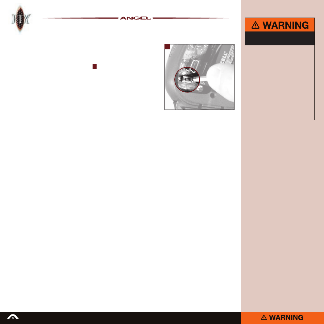
1 Press the internal button located on the
circuit board inside the grip frame.
• The screen will display the internal
options menu.
• Using the navigation button scroll up or
down to highlight the Tournament lock
function.
• Press the navigation button inward to
initiate the Tournament lock features.
• Using the navigation button scroll up or
down to highlight the Lock or Unlock
feature as required.
• Press the navigation button inward to
enable or disable the Tournament lock
function as required.
• You will be asked to conrm that you
wish to continue with this action. Press
the navigation button inwards to confirm
this is correct.
• A padlock icon will be displayed on
the screen indicating the Status of
the tournament lock.
• The following features are affected
by the tournament lock.
Modes
MROF eyes ON
MROF eyes OFF
Dwell
De-Bounce
Shot % filtering
Anti Bolt Stick
In order to adjust any of these features the
tournament lock must be disabled.
ADHERE STRICTLY TO THESE
AND ALL OTHER SAFETY
1
INSTRUCTIONS AND GUIDELINES
Ensure a barrel blocking device is fitted
·
to the ANGEL.
Ensure the hopper is removed from
·
the ANGEL.
Ensure that there are no paintballs
·
in the ANGEL.
Paintball industry standard eye/face/ear
·
and head protection designed specifically
to stop paintballs and meeting ASTM
standard F1776 (USA) or CE standard
(Europe) must be worn by user and any
person within range.
SHOULD YOU BE UNSURE AT ANY STAGE
·
YOU MUST SEEK EXPERT ADVICE.
READ ALL WARNINGS BEFORE ATTEMPTING ANY WORK ON YOUR ANGEL. SHOULD YOU BE UNSURE AT ANY STAGE YOU MUST SEEK EXPERT ADVICE.
Page 15
15
ADHERE STRICTLY TO THESE
AND ALL OTHER SAFETY
INSTRUCTIONS AND GUIDELINES
Ensure a barrel blocking device is fitted
·
to the ANGEL.
Ensure the hopper is removed from
·
the ANGEL.
Ensure that there are no paintballs
·
in the ANGEL.
Paintball industry standard eye/face/ear
·
and head protection designed specifically
to stop paintballs and meeting ASTM
standard F1776 (USA) or CE standard
(Europe) must be worn by user and any
person within range.
SHOULD YOU BE UNSURE AT ANY STAGE
·
YOU MUST SEEK EXPERT ADVICE.
General care
& cleaning
The ANGEL is designed for minimum
maintenance and requires far less lubrication
and greasing of internal parts than other high
performance markers.
For external cleaning of the ANGEL we
recommend the use of a water moistened
cloth. The only oil that is suitable for use in
external cleaning is ANGEL Love Juice or
other synthetic oil, which again should only
be applied sparingly using a cloth. Never
use hydrocarbon based oils, such as WD40,
Vaseline, Duck Oil, Plus Gas, etc to clean or
lubricate the ANGEL as this will damage the
internal seals.
Internal lubrication of the ANGEL can be
achieved without disassembly by removing
your regulator and simply adding a couple of
drops of ANGEL Love Juice oil to your ASA
adapter. Once this has been done re-attach
your regulator as per the instructions on page
6 and shoot the ANGEL 10 times. This will
then disperse the lubricant to all the moving
parts of the ANGEL. This should be done
every 10,000 shots for ANGELs that are used
regularly, or in cases of prolonged spells of
infrequent use, prior to each occasion you
use your ANGEL.
Internal greasing of your ANGEL is required
after disassembly to avoid damage to internal
parts during re-assembly. The only grease
suitable for this purpose is ANGEL Love
Juice Extreme Grease.
For full details on oiling or greasing the
ANGELs internal parts please go to:
http://wdp.tv/e_blast07/140507-news/
may07-news.html#lube
IMPORTANT NOTES:
• No solvents or abrasive cleaning products should be
used. All external and internally accessible moving parts
should be lubricated using light synthetic oil only.
• All threads on the ANGEL, except those for the ANGEL
accessory mountings at the base of the grip frame are metric.
• ANGEL accessory mountings use industry standard
10/32 UNF at centres 0.75” (20mm).
READ ALL WARNINGS BEFORE ATTEMPTING ANY WORK ON YOUR ANGEL. SHOULD YOU BE UNSURE AT ANY STAGE YOU MUST SEEK EXPERT ADVICE.
• When inserting screws into the bottom of the grip frame
the screw thread length must not exceed 0.375” (10mm)
otherwise damage will occur to the electronics.
• We recommend that you remove the righthand cheek cover
and battery when inserting these screws and ensure that the
screws do not project into the circuit board cavity when fitting.
• The ANGEL should never be immersed into water
otherwise damage may occur to the electronics.
Page 16
16
Mini reg removal
& assembly
The mini-regulator is a second stage
regulator that is used to control the velocity
and regulate the gas pressure. It can be
deleted, but only if a suitable first stage
regulator is used that incorporates a high
flow and good regulation properties across
the tank pressure range.
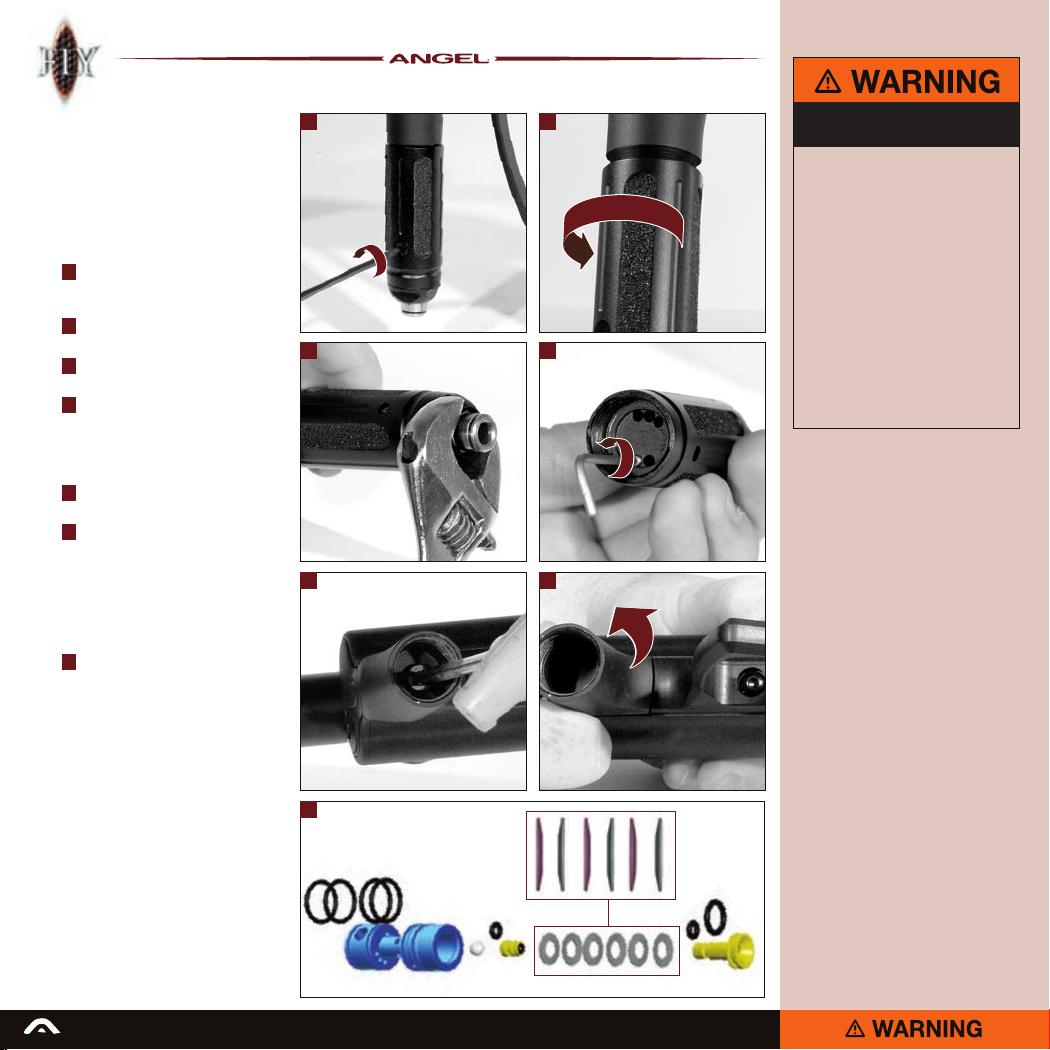
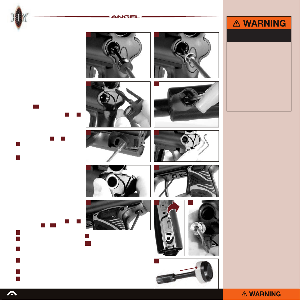
1 Remove the velocity adjuster screw
located on the fore grip using a 3mm
Allen wrench.
2 Unscrew the bottom section of the fore
grip and remove.
3 Remove the fore grip cap using a suitable
wrench.
4 Using the extraction tool provided,
remove the minireg cartridge.
It may be necessary to remove the fore grip
completely in order to facilitate access to the
underside of your ANGEL. To do this:
5 Using a 4mm Allen wrench remove the
fore grip retention screw.
6 Remove the top section of the fore grip.
Note: If replacement of the macro line
hose connector is required - remove the
regulator end cap from the fore grip before
attempting to replace the fitting. Failure to
do so can result in damage to the regulator
end cap or the fore grip.
7 Minireg cartridge assembly.
Note the spring stack order.
1 2
3
5 6
ADHERE STRICTLY TO THESE
AND ALL OTHER SAFETY
INSTRUCTIONS AND GUIDELINES
Ensure a barrel blocking device is fitted
·
to the ANGEL.
Ensure the hopper is removed from
·
the ANGEL.
Ensure that there are no paintballs
·
in the ANGEL.
Always remove the first stage regulator
·
and release all residual gas pressure from
the ANGEL before disassembly.
The ANGEL can hold a small residual
·
gas charge, typically two shots, with the
4
first stage regulator removed. Always
discharge the ANGEL in a safe direction
to relieve this residual gas pressure.
SHOULD YOU BE UNSURE AT ANY STAGE
·
YOU MUST SEEK EXPERT ADVICE.
7
SPRING
STACK
ORDER
READ ALL WARNINGS BEFORE ATTEMPTING ANY WORK ON YOUR ANGEL. SHOULD YOU BE UNSURE AT ANY STAGE YOU MUST SEEK EXPERT ADVICE.
Page 17
17
ADHERE STRICTLY TO THESE
AND ALL OTHER SAFETY
INSTRUCTIONS AND GUIDELINES
Ensure a barrel blocking device is fitted
·
to the ANGEL.
Ensure the hopper is removed from
·
the ANGEL.
Ensure that there are no paintballs
·
in the ANGEL.
Paintball industry standard eye/face/ear
·
and head protection designed specifically
to stop paintballs and meeting ASTM
standard F1776 (USA) or CE standard
(Europe) must be worn by user and any
person within range.
SHOULD YOU BE UNSURE AT ANY STAGE
·
YOU MUST SEEK EXPERT ADVICE.
1 2
43
5 5
6 7 8
Rubber finger detent
replacement
The ANGEL FLY incorporates the new 3
piece eye cover strap. This eye cover strap
incorporates the improved ADB fingers and
is designed for ease of replacement of the
ADBs and trouble free cleaning of the ANGEL
eyes, if required.
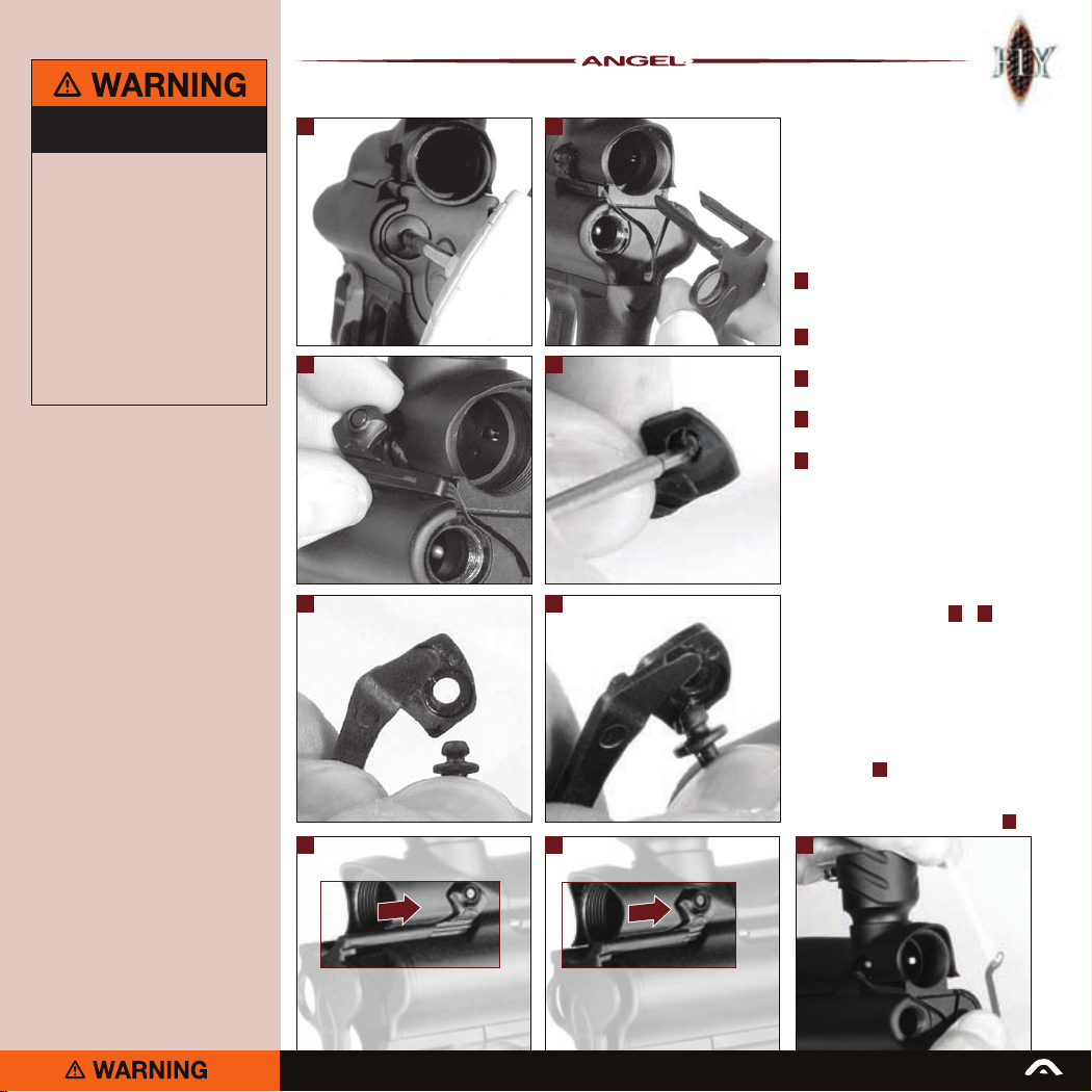
1 Remove the volume chamber
maintenance plug with a 4mm Allen
wrench.
2 Slide the front section of the eye cover
forward and remove.
3 Carefully remove the eye cover arms
from either side of the ANGEL.
4 Using a 2mm Allen wrench (or similar)
push out the ADB finger to be replaced.
5 Take a new ADB finger and insert the
grommet into the retaining hole of the
eye cover arm.
Repeat this process for the other side.
To reassemble, reverse the above
procedure.
Note: It is important that the front section
of the eye cover is located correctly on the
eye cover arms as shown in
Also note that it is important not to splay
the eye cover arms too far apart. This may
result in damage to the eye cover.
6 + 7
.
Angel Eyes sensor
cleaning
Carefully remove the eye cover arms as
shown in point 3 above.
Carefully extract the eye sensor from its
housing and gently remove any grease or
debris build-up using a clean cotton bud 8 .
READ ALL WARNINGS BEFORE ATTEMPTING ANY WORK ON YOUR ANGEL. SHOULD YOU BE UNSURE AT ANY STAGE YOU MUST SEEK EXPERT ADVICE.
Page 18
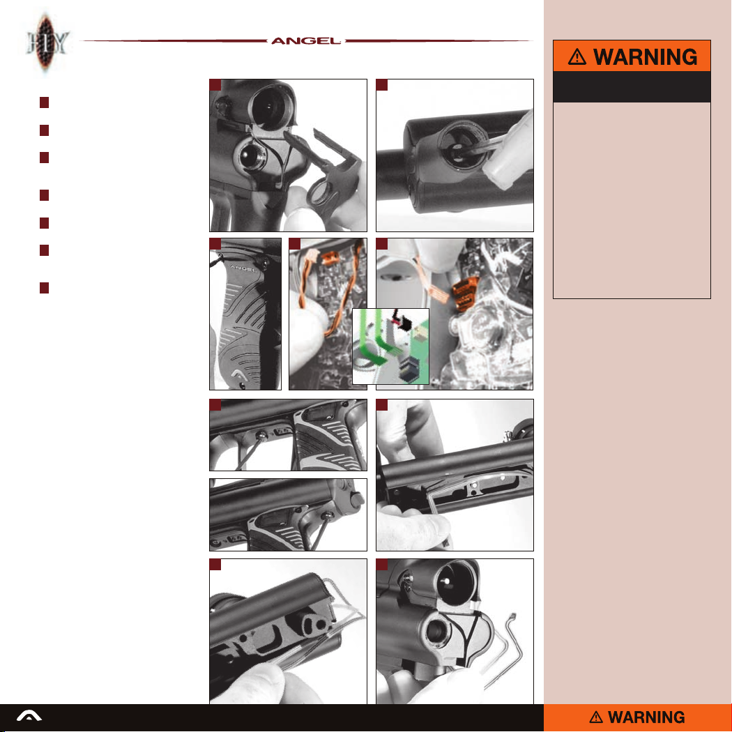
18
Eye ribbon removal
1 Remove the eye cover as shown on
page 17.
2 Remove the fore grip as shown on
page 16.
3 Remove the right hand grip cheek by
removing the 3 screws using a suitable
2mm Allen wrench.
4 Carefully unplug the solenoid from the
board.
5 Carefully unplug the eye ribbons from
the board.
6 Remove the two screws retaining the grip
frame using a 2mm Allen wrench and
remove the grip frame.
7 Carefully remove the eye ribbon from the
ribbon recess.
To rebuild, reverse this procedure.
1 2
4 53
6 7
ADHERE STRICTLY TO THESE
AND ALL OTHER SAFETY
INSTRUCTIONS AND GUIDELINES
Ensure a barrel blocking device is fitted
·
to the ANGEL.
Ensure the hopper is removed from
·
the ANGEL.
Ensure that there are no paintballs
·
in the ANGEL.
Always remove the first stage regulator
·
and release all residual gas pressure from
the ANGEL before disassembly.
The ANGEL can hold a small residual
·
gas charge, typically two shots, with the
first stage regulator removed. Always
discharge the ANGEL in a safe direction
to relieve this residual gas pressure.
SHOULD YOU BE UNSURE AT ANY STAGE
·
YOU MUST SEEK EXPERT ADVICE.
7
READ ALL WARNINGS BEFORE ATTEMPTING ANY WORK ON YOUR ANGEL. SHOULD YOU BE UNSURE AT ANY STAGE YOU MUST SEEK EXPERT ADVICE.
7
Page 19
19
ADHERE STRICTLY TO THESE
AND ALL OTHER SAFETY
INSTRUCTIONS AND GUIDELINES
Ensure a barrel blocking device is fitted
·
to the ANGEL.
Ensure the hopper is removed from
·
the ANGEL.
Ensure that there are no paintballs
·
in the ANGEL.
Always remove the first stage regulator
·
and release all residual gas pressure from
the ANGEL before disassembly.
The ANGEL can hold a small residual
·
gas charge, typically two shots, with the
first stage regulator removed. Always
discharge the ANGEL in a safe direction
to relieve this residual gas pressure.
SHOULD YOU BE UNSURE AT ANY STAGE
·
YOU MUST SEEK EXPERT ADVICE.
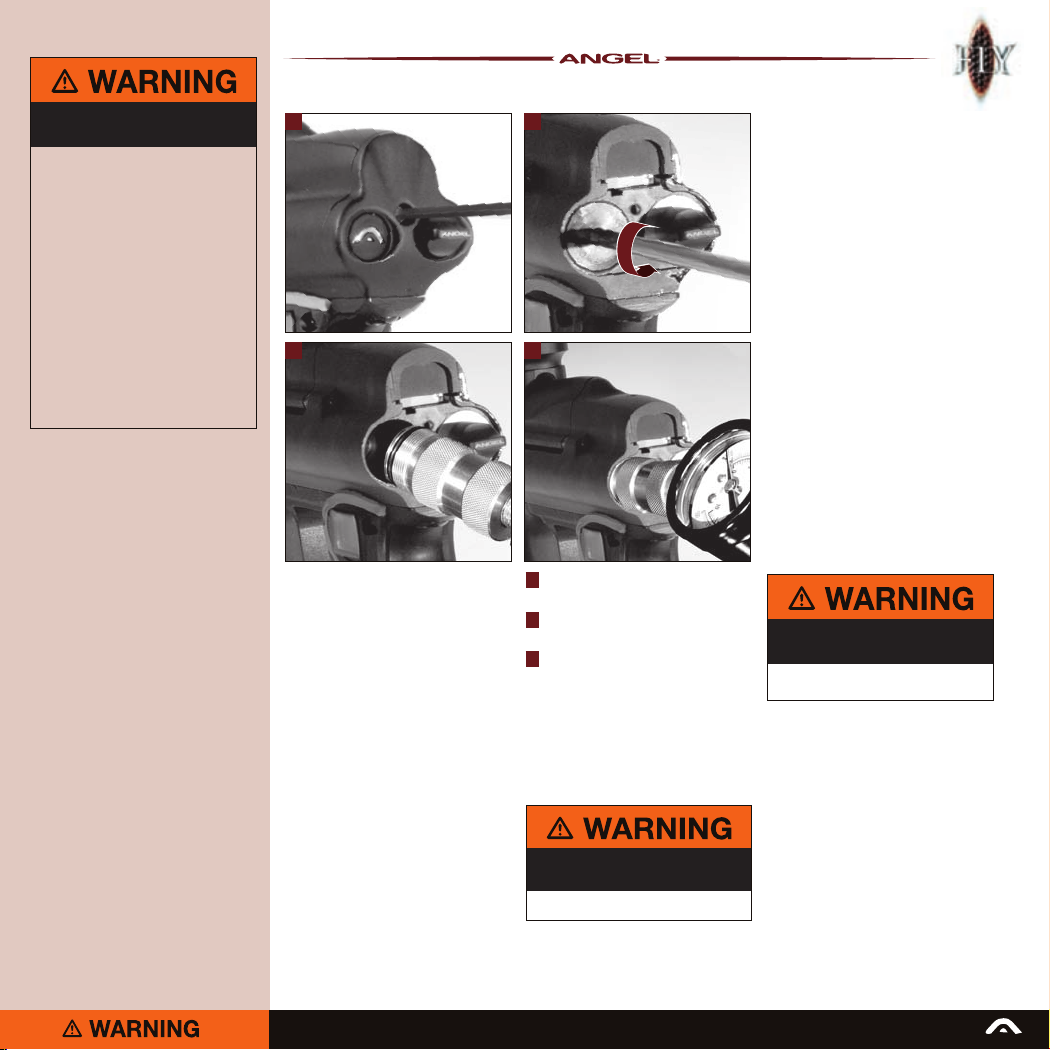
1 2
3 3
1 Remove the back plate retaining screw
using a 2.5mm Allen wrench.
2 Remove the LPR chamber plug using
a 4mm Allen wrench.
3 Screw in the LPR pressure gauge until
it stops turning.
Make a note of the pressure reading.
Should the reading be too high or low
proceed to the next stage -
LPR Adjustment page 20.
Note: Remove the pressure gauge, replace
the LPR chamber plug and back plate and
re-gas your ANGEL.
LPR pressure test
The low pressure regulator controls the
pneumatic cycle of the ANGEL, and is located
in the left hand chamber at the rear of the
ANGEL body.
The pressure needs to be approximately 60psi
(4.14 bar) output from an input pressure of
270psi from the second stage regulator.
Your ANGEL has been tested and tuned
to its optimum operating pressure at the
factory, using a 450psi input. The ANGEL LPR
utilizes shims, as this is the best method of
maintaining its optimum operating pressure.
If you are using a high pressure system you
may need to reset the LPR. You may also
need to adjust the LPR once your ANGEL has
bedded in, but only if you are experiencing
low velocity on your factory settings. Once
this is done you should only need to adjust
the LPR if you change your Air/Nitrogen
system.
LPR adjustment is achieved by the addition
or removal of shims. Each shim equals
approximately 2psi (0.14bar). We recommend
the use of the optional service tools and
lubrication of parts with LOVE JUICE
Extreme Grease only.
ADHERE STRICTLY TO THESE
AND ALL OTHER SAFETY
INSTRUCTIONS AND GUIDELINES
Ensure that the ANGEL is de-gassed and
·
switched off.
ADHERE STRICTLY TO THESE
AND ALL OTHER SAFETY
INSTRUCTIONS AND GUIDELINES
THE ANGEL IS LIVE AND CAPABLE
·
OF DISCHARGING.
• Fire 6 shots with NO paintballs present to
stabilize the LPR pressure.
READ ALL WARNINGS BEFORE ATTEMPTING ANY WORK ON YOUR ANGEL. SHOULD YOU BE UNSURE AT ANY STAGE YOU MUST SEEK EXPERT ADVICE.
Page 20
20
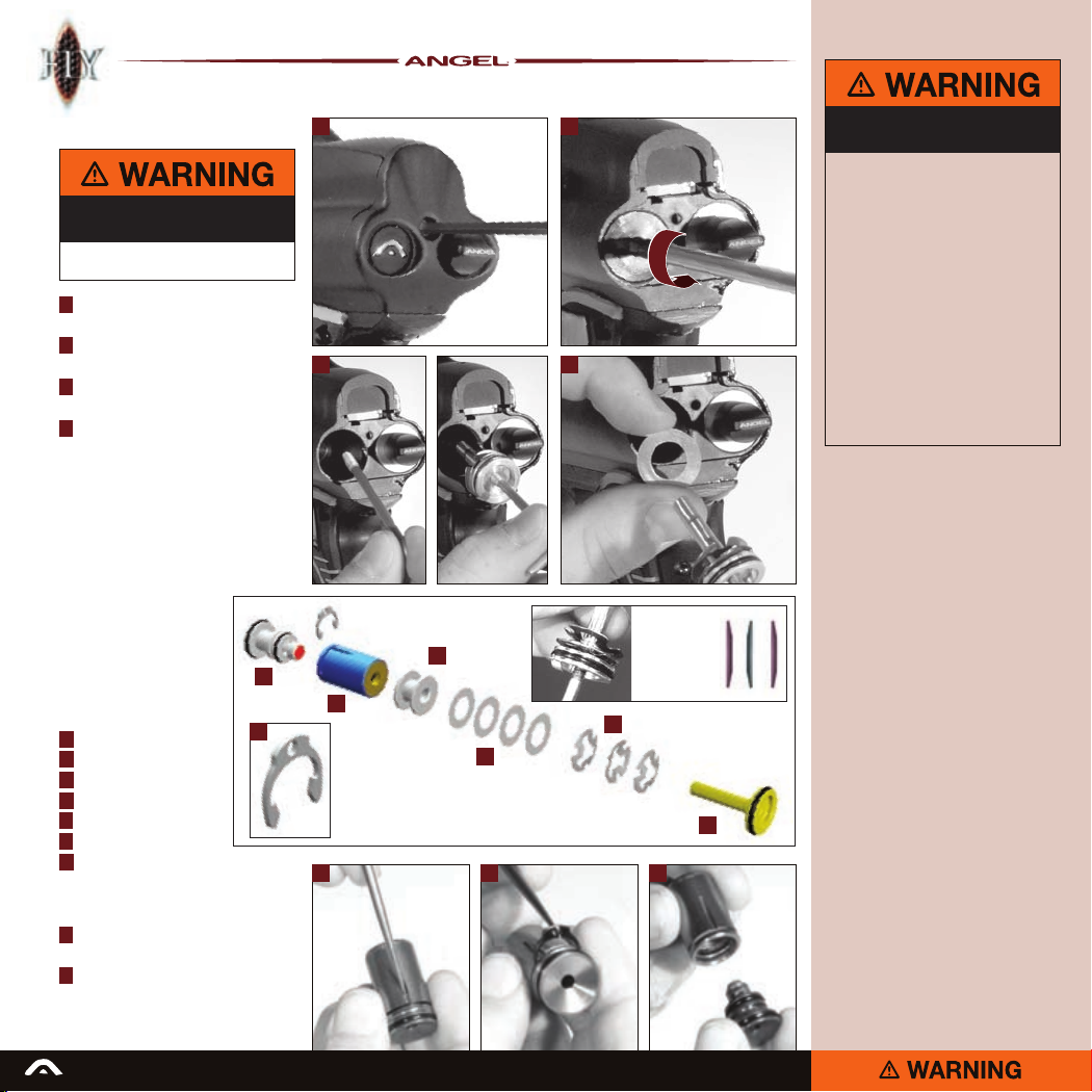
LPR Adjustment
ADHERE STRICTLY TO THESE
AND ALL OTHER SAFETY
INSTRUCTIONS AND GUIDELINES
Ensure that the ANGEL is de-gassed and
·
switched off.
1 Remove the back plate retaining screw
using a 2.5mm Allen wrench.
2 Remove the LPR chamber plug using
a 4mm Allen wrench.
3 Using the extraction tool provided,
withdraw the LPR piston carefully.
4 Add or remove shims to increase
or decrease pressure respectively.
One shim equates to approximately
2 psi change in pressure.
Replace the LPR piston, LPR chamber plug,
back plate and re-gas your ANGEL.
To check the LPR pressure see page 19.
LPR assembly
The LPR may be serviced
once it has been removed by
following the LPR assembly
procedure on page 21. The
serviceable parts are the
external ‘O’ rings and the
LPR spool.
A LPR spool
B LPR body
C Piston spacer
D LPR shims
E LPR spring stack
F LPR piston
G LPR circlip
A
G
LPR spool removal
5 Using a suitable pick remove the LPR circlip
from the LPR body.
6 With the LPR circlip removed separate the
LPR spool from the LPR body.
1 2
3 4
Note:
The order
STACK
ORDER
of the three
tri-active springs
should not be
altered.
E
C
B
D
SPRING
5 5 6
ADHERE STRICTLY TO THESE
AND ALL OTHER SAFETY
INSTRUCTIONS AND GUIDELINES
Ensure a barrel blocking device is fitted
·
to the ANGEL.
Ensure the hopper is removed from
·
the ANGEL.
Ensure that there are no paintballs
·
in the ANGEL.
Always remove the first stage regulator
·
and release all residual gas pressure from
the ANGEL before disassembly.
The ANGEL can hold a small residual
·
gas charge, typically two shots, with the
first stage regulator removed. Always
discharge the ANGEL in a safe direction
to relieve this residual gas pressure.
SHOULD YOU BE UNSURE AT ANY STAGE
·
YOU MUST SEEK EXPERT ADVICE.
F
READ ALL WARNINGS BEFORE ATTEMPTING ANY WORK ON YOUR ANGEL. SHOULD YOU BE UNSURE AT ANY STAGE YOU MUST SEEK EXPERT ADVICE.
Page 21
21
ADHERE STRICTLY TO THESE
AND ALL OTHER SAFETY
INSTRUCTIONS AND GUIDELINES
Ensure a barrel blocking device is fitted
·
to the ANGEL.
Ensure the hopper is removed from
·
the ANGEL.
Ensure that there are no paintballs
·
in the ANGEL.
Always remove the first stage regulator
·
and release all residual gas pressure from
the ANGEL before disassembly.
The ANGEL can hold a small residual
·
gas charge, typically two shots, with the
first stage regulator removed. Always
discharge the ANGEL in a safe direction
to relieve this residual gas pressure.
SHOULD YOU BE UNSURE AT ANY STAGE
·
YOU MUST SEEK EXPERT ADVICE.
2 31
4 5 6
8 9 11
10
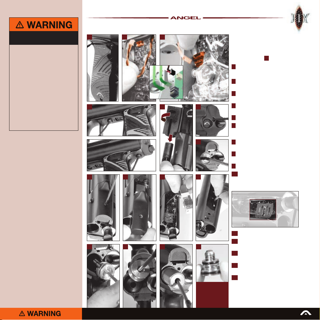
LPR removal
If you are experiencing operating pressure
inconsistency, this may be due to a damaged
spool seal on your LPR. This seal is shown in
red on the LPR Spool A shown on page 20.
1 Remove the right hand grip cheek by
removing the 3 screws using a suitable
2mm Allen wrench.
2 Carefully unplug the solenoid from the
board.
3 Carefully unplug the eye ribbons from
the board.
4 Remove the two screws retaining the grip
frame using a 2mm Allen wrench.
5 Remove the bolt as described on page 7.
6 Remove the back plate retaining screw
(2.5mm Allen wrench) and remove the
back plate.
7
7 Remove the LPR chamber plug using
a 4mm Allen wrench.
8 Loosen the top plate retaining screw using
a 2.5mm Allen wrench...
9 ...and slide the top plate from the body.
10 Carefully lift and remove the solenoid
- carefully extracting the solenoid plugs
from the grip frame housing noting the
orientation of the gasket.
11 Extract the LPR retaining pin.
12 Remove the LPR piston using the
12
READ ALL WARNINGS BEFORE ATTEMPTING ANY WORK ON YOUR ANGEL. SHOULD YOU BE UNSURE AT ANY STAGE YOU MUST SEEK EXPERT ADVICE.
13 14
15
To remove the
LPR spool from
the LPR body see
page 20 -
LPR spool removal
extraction tool supplied.
13 Using a blunt pick remove the solenoid
piston spacer.
14 Using a blunt pick, extract the
LPR body.
15 Check the spool seal for signs of
damage and replace spool assembly if
necessary. The spool assembly is part of
the comprehensive ANGEL spares kit.
To rebuild, reverse this procedure.
Page 22
22
Exhaust valve stem
removal
The magnetic exhaust valve in your ANGEL
FLY reduces its working pressure by over
80psi (30%) on the ANGEL A1. The ANGEL
FLY’s 200 psi working pressure reduces its
kick, making your ANGEL FLY even softer
on paint than the ANGEL A1. If you are
experiencing gas leaking from the breech
area, first ensure your tank is delivering at
least 200 psi to your ANGEL. If you are still
experiencing operating pressure related
problems with your ANGEL, such as gas
leaking from the breech area, inability to
achieve the required velocity or increased
noise when shooting, your ANGEL may have
a damaged exhaust stem face seal. This seal
is shown in 11 and can be easily accessed
by removing the exhaust valve stem assembly
following the instructions in points 1 and 2
below. Once removed, inspect the face seal.
If the face of this seal is scored, or
impregnated with grit or dirt or is excessively
deformed, it is necessary to replace the
exhaust valve stem assembly by reversing
the procedure in points 1 and 2 below.
Remove the volume chamber
1
maintenance plug using
a 4mm Allen wrench.
Insert a suitable Allen wrench into the
2
cavity. The exhaust valve stem (which is
magnetic) will be attracted to the Allen
wrench and can be easily removed.
Exhaust valve guide
removal
Once the valve stem assembly has been
replaced if you are still experiencing the
same problem you will need to inspect the
O-ring on the exhaust valve guide nearest
the face seal for nicks or tears and replace
if necessary. If there are no signs of damage
to this O-ring, inspect the face seal seat for
dents or scratches and replace if necessary,
following the instructions in points 1 and 2
above and points 3 to 10 below.
3 Slide off the eye cover.
4 Remove the fore grip as shown
on page 16.
5 Remove the end plug retention pin using
the extraction tool provided.
6 Carefully move eyes out of the way
to avoid damage.
7 Remove the end plug.
8 Remove the two screws retaining the grip
frame using a 2mm Allen wrench.
1
3 4
5
7
8
9 Remove the LPR retaining pin.
10 Using a blunt pick, carefully extract
the exhaust valve guide as shown.
Important notes for the re-assembly
of components:
• Ensure exhaust valve stem assembly
is located in the exhaust body within
the ANGEL.
• Ensure that the end cap is located
correctly.
2
6
8
9
11
Exhaust valve
guide seal
ADHERE STRICTLY TO THESE
AND ALL OTHER SAFETY
INSTRUCTIONS AND GUIDELINES
Ensure a barrel blocking device is fitted
·
to the ANGEL.
Ensure the hopper is removed from
·
the ANGEL.
Ensure that there are no paintballs
·
in the ANGEL.
Paintball industry standard eye/face/ear
·
and head protection designed specifically
to stop paintballs and meeting ASTM
standard F1776 (USA) or CE standard
(Europe) must be worn by user and any
person within range.
SHOULD YOU BE UNSURE AT ANY STAGE
·
YOU MUST SEEK EXPERT ADVICE.
10
READ ALL WARNINGS BEFORE ATTEMPTING ANY WORK ON YOUR ANGEL. SHOULD YOU BE UNSURE AT ANY STAGE YOU MUST SEEK EXPERT ADVICE.
Page 23
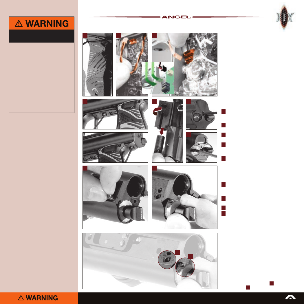
23
ADHERE STRICTLY TO THESE
AND ALL OTHER SAFETY
INSTRUCTIONS AND GUIDELINES
Ensure a barrel blocking device is fitted
·
to the ANGEL.
Ensure the hopper is removed from
·
the ANGEL.
Ensure that there are no paintballs
·
in the ANGEL.
Paintball industry standard eye/face/ear
·
and head protection designed specifically
to stop paintballs and meeting ASTM
standard F1776 (USA) or CE standard
(Europe) must be worn by user and any
person within range.
SHOULD YOU BE UNSURE AT ANY STAGE
·
YOU MUST SEEK EXPERT ADVICE.
2 31
4 5 6
7
8 9
A
B
READ ALL WARNINGS BEFORE ATTEMPTING ANY WORK ON YOUR ANGEL. SHOULD YOU BE UNSURE AT ANY STAGE YOU MUST SEEK EXPERT ADVICE.
RAM removal
You may need to remove your Ram if the
ANGEL’s hammer has come loose or the
Ram is leaking. To establish if a gas leak is
coming from the Ram, rst check your LPR
pressure is above 40psi and if so open the
breech block and listen for gas emitting from
the breech pin slot. If gas is emitting from the
breech port, it is not Ram related and will be
due to your exhaust valve. If gas is emitting
from the slot, remove your Ram following
the instructions below and inspect the three
O-rings for damage and replace if necessary.
If the O-rings are not damaged, inspect the
Ram shaft for scratches or dents and replace
the complete Ram if necessary, following the
instructions below.
Remove the right hand grip cheek by
1
removing the 3 screws using a suitable
2mm Allen wrench.
2 Carefully unplug the solenoid from the
board.
3 Carefully unplug the eye ribbons from
the board.
4 Remove the two screws retaining the grip
frame using a 2mm Allen wrench and
remove the grip frame.
5 Turn the breech release knob clockwise
and remove the bolt from the breech.
NOTE: the breech will not open unless
the bolt is in the backward position.
6 Remove the back plate retaining screw
(2.5mm Allen wrench) and remove the
back plate.
7 Remove the LPR chamber plug using
a 4mm Allen wrench.
8 Withdraw the Ram retaining pin.
9 The Ram can now be withdrawn.
To rebuild, reverse this procedure.
IMPORTANT NOTES:
For re-assembly of components
• Ensure the Ram assembly is lubricated
with Love Juice Extreme Grease prior
to refitting.
• Ensure the Ram assembly external
O-rings are not damaged.
• Ensure the Ram assembly is inserted
slowly to prevent damage to the
O-rings.
• Note that, to replace the Ram retaining
pin, the holes in the gun body A and in
the Ram itself B must be aligned.
Page 24
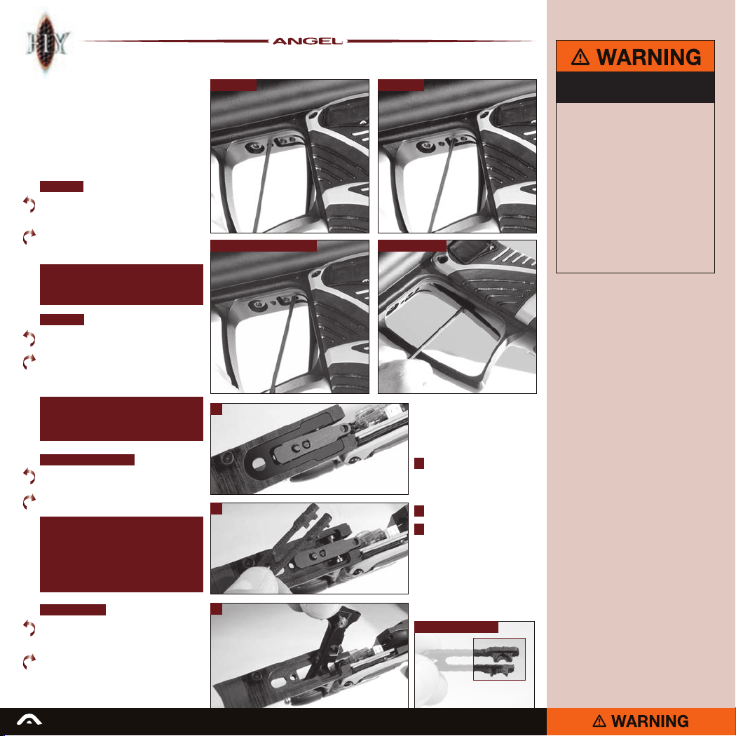
24
Trigger adjustment
The trigger system has four adjustable
points: back stop, front stop, magnetic
return strength control and activation point.
When adjusting the trigger it is advisable
to set both the front and back stop positions
before you proceed to set the return
strength or activation point.
Back stop
Counter-clockwise = moves the point
at which the trigger stops - backwards,
towards the grip cheek
Clockwise = moves the point at which
the trigger stops - forwards, away from
the grip cheek
Note: It is important not to over adjust the
back stop position set screw in this direction
as it will result in not enough travel for
a trigger pull to activate the button.
Front stop
Counter-clockwise = moves the point
from which the trigger-pull starts forwards,
away from the grip cheek
Clockwise = moves the point from which
the trigger-pull starts backwards, towards
the grip cheek
Note: It is important not to over adjust
the front stop position set screw in this
direction as it will result in not enough
return travel for the trigger to reset the
Magnet return strength
Counter-clockwise = makes magnet
return strength weaker.
Clockwise = makes magnet return
strength stronger
It is important not to over adjust this portion
of the trigger as it will negate the position
of the front stop set screw. For this reason
it is advisable that during the setup of the
trigger you should wind the magnetic return
strength adjuster screw counter-clockwise
several turns so that it does not interfere with
the adjustment of the front stop set screw.
Activation point
Counter-clockwise = moves the point
at which the trigger will activate closer
to the end of the trigger pull
Clockwise = moves the point at which
the trigger will activate closer to the start
of the trigger pull.
READ ALL WARNINGS BEFORE ATTEMPTING ANY WORK ON YOUR ANGEL. SHOULD YOU BE UNSURE AT ANY STAGE YOU MUST SEEK EXPERT ADVICE.
Back stop Front stop
Magnetic return strength Activation point
1
2
3
Trigger removal
Firstly remove the grip frame.
See page 21 gs 1 - 4.
Then:
1 With the grip frame removed
you now have access to the
trigger clamp plate and the
trigger itself
2 Remove the trigger clamp plate
3 Remove the trigger
Important Note:
When reassembling the trigger
note the orientation of the trigger
clamp plate and ensure that the
clamp plate is located correctly
on the trigger bearings.
Trigger clamp plate
Locate onto
trigger bearings
ADHERE STRICTLY TO THESE
AND ALL OTHER SAFETY
INSTRUCTIONS AND GUIDELINES
Ensure a barrel blocking device is fitted
·
to the ANGEL.
Ensure the hopper is removed from
·
the ANGEL.
Ensure that there are no paintballs
·
in the ANGEL.
Paintball industry standard eye/face/ear
·
and head protection designed specifically
to stop paintballs and meeting ASTM
standard F1776 (USA) or CE standard
(Europe) must be worn by user and any
person within range.
SHOULD YOU BE UNSURE AT ANY STAGE
·
YOU MUST SEEK EXPERT ADVICE.
Page 25
USEFUL CONVERSIONS
Listed are some useful conversions
relating to pressure, velocity, mass
and distance.
PRESSURE
1 atm = 1.01325 bar
1 atm = 14.6959 psi
1 bar = 14.5038 psi
1 psi = 0.0689476 bar
VELOCITY
1 Ft/s = 0.3048 m/s
1 Ft/s = 0.6818180 Mph
1 m/s = 3.28084 Ft/s
1 m/s = 2.23694 Mph
1 m/s = 3.6 Kph
MASS
1 g = 0.05274 oz
1 Kg = 2.20462 Ib
1 oz = 0.0283495 Kg
DISTANCE
1 mm = 0.0393701 Inch
1 Inch = 25.4mm
1 thou = 25.4 micron
1 micron = 0.0393701 thou
FORMULA TO CONVERT
FEET PER SECOND (Ft/s)
TO FOOT Lbs (Force)
1 foot Ibs (force) = 1.35582 Joules
1 Joule = 0.737562 foot Ibs (force)
1 Gram = 15.4324 Grains
1 Grain = 0.000142857 lb
1 lb = 7000 Grains
Velocity squared x Projectile weight
VELOCITY = Ft/s (feet per second)
PROJECTILE WEIGHT = GRAINS
Therefore a paintball @ 3.2grams
@ 300Ft/s= 9.9 foot lbs (ftlbs)
25
PROBLEM SOLUTION PAGE
ANGEL WILL NOT FIRE
No air or nitrogen present? Propellant Air/Nitrogen Supply. 6
Is the battery operational? Change the battery. 4
Is the ANGEL in ‘SAFE’? Making the ANGEL ‘LIVE’. 3
Is the trigger not closing the button? Trigger Adjustment. 24
Is the trigger not releasing the button? Trigger Adjustment. 24
Is the bolt jammed forward? Clear the blockage from breech. 7
Is the LPR set correctly? LPR Adjustment. 20
Is the OPTO Trigger functioning? Trigger Adjustment. 24
Are the ANGEL Eyes switched on? Ensure paint is present. –
Are the ANGEL Eyes optics blocked? Clean the ANGEL Eyes Optics. –
VELOCITY VARIATIONS
Are good quality paintballs being used? Use good paintballs. –
Is the barrel bore correct for the paint? Use suitable barrel. –
Is the paint swollen, cold or hot? Review your storage of paint. –
Is the barrel bore clean? Clean the barrel. –
Is the tank reg choking on gas supply? Check tank regulator assembly. –
Is the tank reg operating correctly? Check tank regulator assembly. –
Is the minireg operating correctly? Minireg Service. 16
Is the minireg choking on gas supply? Minireg Service. 16
Are unsuitable after market parts tted? Use genuine ANGEL parts. –
Is the bolt worn? Replace Bolt. 7
Is the LPR set correctly? LPR Adjustment. 20
Is the valve dwell set correctly? Dwell Adjustment. 11
Is the rst shot low? Increase Dwell Time. 11
VELOCITY TOO LOW / HIGH
Is the high pressure reg set correctly? Check at gas source. 6
Is the velocity adjuster screw set correctly? Velocity adjustment. 7
Is the bolt sticking? Check rubber nger detents. 17
Is the LPR set correctly? LPR Adjustment. 20
Is the valve dwell set correctly? Dwell Adjustment. 11
GAS LEAKING
From the back cover? Check solenoid valve. 21(gs 6-10)
From the Ram assembly? Check Ram body O-rings. 23
From the gas joints? Check all ttings. -
From the exhaust valve? Exhaust valve stem/guide. 22
READ ALL WARNINGS BEFORE ATTEMPTING ANY WORK ON YOUR ANGEL. SHOULD YOU BE UNSURE AT ANY STAGE YOU MUST SEEK EXPERT ADVICE.
Page 26
26
PROBLEM SOLUTION PAGE
BREAKING PAINTBALLS
Is the paint too fragile? Use less fragile paint. –
Is the barrel bore correct for the paint? Use a suitable barrel. –
Is the paint swollen, cold or hot? Review your storage of paint. –
Are the ANGEL Eyes switched on? Switch ANGEL Eyes on 5
Are the ANGEL Eyes functioning? ANGEL Eyes Test. 5/17
Is the loader battery weak/dead? Replace batteries. –
Is a suitable working loader tted? Check loader specications. –
Is the correct paint type selected? Change Paint Type settings. 12
Is the rate of re set too high? MROF Adjustment. 12
Are the rubber nger detents functioning? Clean or replace. 17
Is the paint too fragile for the loader? Change paint to tougher grade. –
CHOPPING PAINTBALLS
Is the loader battery weak/dead? Replace batteries. –
Is a suitable working loader tted? Replace loader. –
Is the loader dirty? Clean loader. –
Are the paintballs swollen? Replace the paintballs. –
Are the ANGEL Eyes switched on? Switch ANGEL Eyes on 5
Are the ANGEL Eyes functioning? ANGEL Eyes Test. 5/17
Is the correct paint type setting selected? Change Paint Type settings 12
Is the Rate Of Fire set too high? MROF Adjustment. 12
Are the rubber nger detents functioning? Clean or replace. 17
FIRING TOO SLOWLY
Is the rate of re set correctly? MROF Adjustment. 12
Is the loader battery weak/dead? Replace batteries. –
Is a suitable working loader tted? Replace loade. –
Is the loader dirty? Clean loader. –
Are the ANGEL Eyes switched on? Switch ANGEL Eyes on 5
Is the correct paint type selected? Change Loader Type settings 12
Is the Rate Of Fire set too low? MROF Adjustment. 12
EXCESSIVE NOISE / GAS CONSUMPTION
Is the valve Dwell set correctly? Dwell Adjustment. 11
Is the LPR pressure set correctly? LPR Adjustment. 20
Is the exhaust valve worn? Exhaust Valve replacement. 22
Is the barrel bore correct for the paint? Use a suitable barrel. –
READ ALL WARNINGS BEFORE ATTEMPTING ANY WORK ON YOUR ANGEL. SHOULD YOU BE UNSURE AT ANY STAGE YOU MUST SEEK EXPERT ADVICE.
Page 27

Terms of warranty - EEC/R.O.W. (excluding usa/canada).
Subject to the conditions set out below
WDP warrants that the ANGEL will
correspond to its specification at the time
of delivery and will be free from defects in
materials and workmanship for a period of
six months from the date of purchase.
WDP gives this warranty subject to the
following conditions:
• Proof of purchase is required in all
warranty claims.
• Warranty is not transferable.
• The company shall be under no liability
in respect of any defect arising from fair
wear and tear.
• Seals, batteries, wiring, circuit boards,
displays and exhaust valves are not
covered by this warranty. Wilful damage,
negligence, abnormal working conditions,
weather, accident, tampering, failure
to follow manufacturers instructions
(whether oral or in writing), misuse or
alteration or repair of the ANGEL without
the company’s written approval will
invalidate this warranty and the company
shall be under no obligation whatsoever
to the purchaser in respect of any of the
above breaches of this warranty.
• The above warranty does not extend
to parts, materials or equipment not
manufactured by the company, in
respect of which the purchaser shall only
be entitled to the benefit of any such
warranty or guarantee as given by the
manufacturer to the company.
This warranty does not cover the following:
• Repairs, alterations or replacements not
authorised by the manufacturer.
• The gradual reduction in performance
linked to the age of the ANGEL or usage.
• Anything caused directly or indirectly by
vandalism or theft.
• Any damage to parts which are recalled
by the Manufacturer.
• Any loss, damage or failure, which
a qualified engineer appointed by the
manufacturer believes could have been
avoided, or was totally or partly caused
by a lack of maintenance.
Subject as expressly provided in these
conditions and except where the goods are
sold to a person dealing as a consumer
(within the meaning of the Unfair Contract
Terms Act 1977) all warranties, conditions
or other terms implied by statute or
common law are excluded to the fullest
extent permitted by law.
Where the goods are sold under a
consumer transaction (as defined by
the Unfair Terms in Consumer Contracts
Regulations SI 1994/3159) the statutory
rights of the purchaser are not affected
by these conditions. Carriage charges in
relation to warranty claims shall be borne
by the customer.
Where any valid claim in respect of
the ANGEL is based in the quality or
condition of the ANGEL or its failure to
meet specification, and such valid claim is
notified to the company in writing and is in
accordance with the company’s standard
terms and conditions of sale, the company
shall be entitled to repair or replace the
goods or the part in question free of charge
or, at the company’s sole discretion, refund
to the purchaser the price of the goods (or
a proportionate part of the price) but the
company shall have no further liability to
the purchaser.
Except in respect of death or personal
injury caused by the company’s negligence,
the company shall not be liable to the
purchaser by reason of any representation,
or any implied warranty, condition or other
term, or any duty at common law, or under
the express terms of this guarantee, for any
direct or indirect, special or consequential
loss or damage, whether to persons or
property, costs, expenses or other claims
for compensation or damages whatsoever
(whether caused by the negligence of
the company, its employees or agents
or otherwise) which arise out of or in
connection with the supply of the ANGEL,
its use, or misuse, or resale by the
purchaser, or any individual, and the
entire liability of the company under or in
connection with the purchase or use or
misuse of the ANGEL shall not exceed the
purchase price of the ANGEL. Purchaser
agrees to adhere strictly to all warnings and
safety procedures and the contents of the
Operator’s Manual.
The laws of England shall govern this
warranty and the purchaser agrees to
submit to the non-exclusive jurisdiction
of the English courts.
The supply and purchase of the ANGEL
is subject to the company’s standard
terms and conditions of sale, a copy of
which is available on request. ANGEL
patents applied for, design rights and all
rights reserved. The ANGEL is marketed
and distributed by WDP Ltd. Company
registered in England No. 2114341 and
WDP Paintball Inc. registered in USA No.
2479769.
No warranty is given to parts not
manufactured by the manufacture,r and
all liability for loss, damage or injury is
excluded.
This warranty must be construed and read
in conjunction with the product’s terms and
conditions of sale.
To make a warranty claim, the purchaser
must first contact the nearest authorised
ANGEL Service Centre for instructions.
A list of authorised ANGEL Service Centres
may be obtained through the WDP website:
www.wdp.tv, or by contacting WDP by mail
at WDP, Metro Triangle, 221 Mount Street,
Nechells, Birmingham, England B7 5QT,
or by fax at: +(44) (0)121 327 3967,
or by calling: +(44) (0)121 328 2228.
27
Page 28

28
Terms of warranty - USA / Canada
1. General Express Warranties.
WDP warrants to the buyer who is
purchasing to place into use (Buyer) only,
that the ANGEL (Product) shall be free
from material manufacturing defects in
materials and workmanship for six months
from the date of purchase, subject to the
requirements, disclaimers and limitations
of this Warranty. This is not a Warranty of
performance, but a limited Warranty as to
the condition of the Product at the beginning
of the Warranty period, this Warranty is only
against such defects and not against any
other failures such as, but not limited to,
those due to wear and tear, exposure to the
elements, unusual operating environments,
misuse, negligence, accident, alteration
or repair in any respect which, in the
judgement of WDP, adversely affects the
condition or operation of the Product. Normal
maintenance and perishable items such as
seals, batteries, wiring, indicator lamps and
exhaust valves are excluded from this limited
Warranty against defects. This Warranty is
not transferable and it may not be waived or
expanded except in writing signed by WDP.
The terms and limitations of this Warranty
shall also apply to any additional goods or
information, which may be distributed by
WDP, relating to the ANGEL.
2. Disclaimer and Limitation of Express and
Implied Warranties.
There are no express Warranties other than
those contained in this Warranty. Whether
or not the Product is to be used exclusively
by the Buyer, there shall be no third party
beneciaries to this Warranty herein. NO
WARRANTY IS PROVIDED TO DISTRIBUTORS
OR DEALERS EXCEPT AS MAY BE
EXPRESSLY PROVIDED IN A SEPARATE
AGREEMENT OF SALE.
All descriptions, illustrations of the Product
and other information in catalogues,
brochures and price lists or otherwise
provided by WDP or others are intended
for general information only. WDP, is not
responsible for any errors or omissions
therein or for any loss or damage resulting
from reliance on them. WDP, does not
warrant that the Product is in compliance
with any law or industry standards,
guidelines or procedures. WDP standard
terms and conditions of sale also apply if
Buyer is a direct purchaser from WDP - WDP
DISCLAIMS ALL IMPLIED WARRANTIES
INCLUDING, BUT NOT LIMITED TO, THOSE
OF FITNESS FOR A PARTICULAR PURPOSE
AND MERCHANTABILITY.
3. Remedy and Limitation of WDP liability.
Defective or non-conforming Product or
parts thereof discovered and returned to
WDP freight prepaid, with proof of purchase,
during the Warranty period shall be repaired
or replaced by WDP without any additional
charge and shipped to Buyer, FOB WDP.
In lieu of repair or replacement, if WDP
elects, WDP may, upon return of such
product and making a determination of
non- conformity or defect, keep the product
and refund the purchase price paid by
Buyer. Buyer’s remedies shall be limited
(even in the event of WDP default of its
Warranty obligations) exclusively to those
provided in this Warranty. UNDER NO
CIRCUMSTANCES SHALL WDP OR ANY
SUPPLIER, DISTRIBUTOR, DEALER, OR
OTHER PERSON BE LIABLE FOR EXEMPLARY,
PUNITIVE, CONSEQUENTIAL OR INCIDENTAL
DAMAGES, NOR FOR ANY AMOUNT IN
EXCESS OF THE BUYER’S PURCHASE PRICE.
Buyer waives any causes of action or theories
of liability including, but not limited to, those
arising under contract, tort, strict liability,
Product liability, statutes, or otherwise,
except as to those specifically provided by
the Uniform Commercial Code (as adopted in
Michigan) as excluded, modified and limited
in this warranty.
4. Additional Consumer Protection.
The products are offered for sale for end use
in supervised commercial establishments
where professional safety codes are
enforced, and not for personal, family
or household use. Nevertheless, if the
Product is determined in a transaction to be
a customer Product under applicable law, the
following provisions shall become applicable:
(a) THE IMPLIED WARRANTIES OF
MERCHANTABILITY OR FITNESS OF THE
PRODUCT FOR A PARTICULAR PURPOSE
THAT CANNOT BE DISCLAIMED ARE
LIMITED IN DURATION TO THE INITIAL
EXPRESS WARRANTY PERIOD.
(b) Some states do not allow limitations on
how long an implied Warranty lasts, so the
above limitation in (a) may not apply.
(c) Some states do not allow the exclusion or
limitation of incidental or consequential
damages, so such limitations may not
apply.
(d) And this Warranty gives buyer specific
legal rights, and buyer may also have
other rights provided for by law.
5. Parts, Service and Training performed
by WDP.
All Warranty and non-Warranty parts, labour
and service, if any, provided by WDP related
to the product are subject to all limitations
and disclaimers of warranties and remedies
provided in this Warranty. The replacement
or repair of a product by WDP does not give
rise to any new Warranty except the Warranty
period provided for herein shall be extended
by the length of any period in which defective
or non-conforming product is in possession
of WDP - WDP may have access to the
Product after purchase of the Product. WDP
is not under any duty to inspect the product
for any defects or any improper use or
modication of the Product, nor to correct
or advise anyone of any such condition,
use or modification, which is observed.
Any notification, which may be given,
is voluntary and subject to all limitations
and disclaimers in this Warranty.
6. User’s Responsibility for Safety and
Indemnification.
It is Buyer’s or other user’s responsibility to
obtain all training and means that may be
necessary to effectively protect all individuals
and property from damage and bodily injury,
which otherwise may result from the use
or maintenance of the Product, and to use
the Product in accordance with operating
instructions and due care.
If operating instructions are not provided
with the Product or have been lost, a copy
will be provided by WDP without cost on
request. The buyer shall use and shall
require all others to use all safety devices
and guards furnished with or intended to be
used with the Product, and to follow proper
safe operating procedures in accordance
with general industry standards and as set
forth in manuals and instruction information
furnished by WDP. If the Buyer fails to
comply with the obligations set forth in this
section, the Buyer shall defend and indemnify
WDP harmless from any claim, liability or
obligation incurred by WDP or its suppliers,
distributors, or dealers to persons injured
directly or indirectly in connection with the
use of the product contrary to this Warranty
or any warning or instruction from WDP
7. Law and Jurisdiction.
This Warranty shall be governed by the laws
of Michigan, and Buyer irrevocably submits
to the non-exclusive jurisdiction of courts
sitting in Michigan to resolve all disputes
arising from or related to this warranty or use
of the Product.
8. Claims and information procedure.
To make a warranty claim, the Buyer must
rst contact the nearest authorised ANGEL
Service Centre for instructions. A list of
authorised ANGEL Service Centres may be
obtained through the WDP website: www.
wdp.tv, or by contacting WDP by mail at:
WDP, Metro Triangle, 221 Mount Street,
Nechells, Birmingham, England, B7 5QT,
or by fax at +44 (0)121 327 3967.
or by calling +44 (0)121 328 2228.
Page 29

 Loading...