

Page 1
IMPORTANT FOR FUTURE REFERENCE
Please complete this information and retain this manual
for the life of the equipment:
Model #: __________________________
Serial #: __________________________
Date Purchased: ___________________
Service & Parts Manual
Covering
SLG Series
AUSTRALIA
UK, MT
L22-348 Rev 1, 5/13
Page 2
FOR YOUR SAFETY
DO NOT store or use gasoline or other flammable vapors or liquids in the
vicinity of this or any other appliance. Do not spray aerosols in the vicinity of
this appliance while it is in operation.
WARNING
Improper installation, alteration, service or maintenance can cause property
damage, injury or death. Read the installation, operating and maintenance
instructions thoroughly before installing or servicing this equipment.
TO THE PURCHASER
Post, in a prominent location, the
instructions to be followed in the event that
an operator smells gas. Obtain this
information from your local gas supplier.
WARNING
There is an open flame inside this appliance.
The unit may get hot enough to set nearby
materials on fire. Keep the area around the
appliance free from combustibles.
WARNING
DO NOT supply the appliance with a gas
that is not indicated on the data plate. If you
need to convert the appliance to another
type of fuel, contact your dealer.
WARNING
DO NOT use an open flame to check for
gas leaks!
WARNING
If gas flow to appliance is interrupted, or pilots
extinguish, wait 5 minutes before attempting to
relight the pilot to allow any residual gas in
appliance to dissipate.
WARNING
Ensure that the appliance can get enough air to
keep the flame burning correctly. If the flame is
starved for air, it can give off a dangerous carbon
monoxide gas. Carbon monoxide is a clear
odorless gas that can cause suffocation.
WARNING
Adequate means must be provided to limit the
movement of this appliance without depending on
the gas line connection. Single appliances
equipped with legs must be stabilized by installing
anchor straps. All appliances equipped with
casters must be stabilized by installing restraining
chains. If a flexible gas line is used, an additional
restraining cable must be connected at all times
when the appliance is in use.
An appliance equipped with casters and a flexible
gas line must be connected to the gas supply with
a quick disconnect device. This quick disconnect
must comply with AS4631 (Australia only). To limit
the movement of the appliance without depending
on the connector or quick disconnect, a
restraining cable must also be installed.
Installation of this appliance must be done by a
qualified professional. This appliance should be
inspected by a qualified professional on an annual
basis to insure safe and proper operation.
In Australia, this appliance must be installed in
accordance with AS 5601 (current revision) or local
codes, or National Codes as applicable.
This appliance must be installed by a competent
installer. Install only in a well-ventilated area.
Read the instructions before operating this
appliance.
If the appliance has a power supply, it must be
disconnected before servicing or cleaning this
appliance.
Do not attempt to move this appliance when the
unit is at operating temperature. Serious personal
injury could result if skin comes in contact with the
hot surfaces.
DO NOT sit or stand on this appliance. Serious
injury could result from falling or contact with hot
shortening/oil.
WARNING
WARNING
WARNING
WARNING
WARNING
WARNING
WARNING
L22-348 Rev 1, 5/13
Page 3

TABLE OF CONTENTS
1 Leg Installation and Leveling ........................................................................................................................... 2
1.1 Installation Clearances ............................................................................................................................ 2
1.2 Gas Connection ....................................................................................................................................... 2
1.3 Gas Connection and Sealing Compound ................................................................................................ 3
1.4 Fuel Supply Line Leak and Pressure Testing ......................................................................................... 3
2 INITIAL ADJUSTMENTS ................................................................................................................................. 3
2.1 Pilot Flame Adjustment after gas valve replacement .............................................................................. 3
2.2 Main Burner System Adjustment ............................................................................................................. 4
3 Thermostat Calibration ..................................................................................................................................... 4
3.1 Thermostat Calibration Check (Standard) ............................................................................................... 4
3.2 For Gas Operated and Electric Thermostats refer to the following procedure. ...................................... 5
4 Trouble Shooting .............................................................................................................................................. 6
4.1 Testing the Thermocouple: ...................................................................................................................... 7
4.2 Testing the Radix wire: ............................................................................................................................ 7
4.3 Testing the Hi Limit: ................................................................................................................................. 7
4.4 Testing the Gas Valve: ............................................................................................................................ 7
5 SLG40 Exploded Parts Diagram ...................................................................................................................... 8
5.1 SLG40 Exploded Parts List ..................................................................................................................... 9
6 SLG100 Exploded Parts Diagram .................................................................................................................. 10
6.1 SLG100 Exploded Parts List ................................................................................................................. 11
7 SLG40 Gas Assembly Exploded AU & CE Diagram .................................................................................... 12
7.1 SLG40 Gas Assembly Exploded AU & CE Parts .................................................................................. 13
8 SLG100 Gas Supply Exploded AU & CE Diagram ........................................................................................ 14
8.1 SLG100 Gas Supply Exploded AU & CE Parts ..................................................................................... 15
9 TSTAT Assembly Exploded AU Diagram ...................................................................................................... 16
9.1 TSTAT Assembly Exploded AU Parts ................................................................................................... 17
1
L22-348 R1 5/13
Page 4
Combustible
Construction
Non-
Combustible
Construction
Back
6 in. (15 cm)
6 in. (15 cm)
Sides
6 in. (15 cm)
6 in. (15 cm)
Floor
N/A*
4 ¾ (11.5 cm)
1 Leg Installation and Leveling
This appliance must be installed with legs; it cannot be curb mounted. Curb
mounting will seriously inhibit this appliances ability to effect proper
combustion.
WARNING
This appliance must be installed with the legs provided by the
manufacturer.
WARNING
Do not install legs or perform leveling procedure when unit is in operation or full of cooking medium.
Serious injury could result.
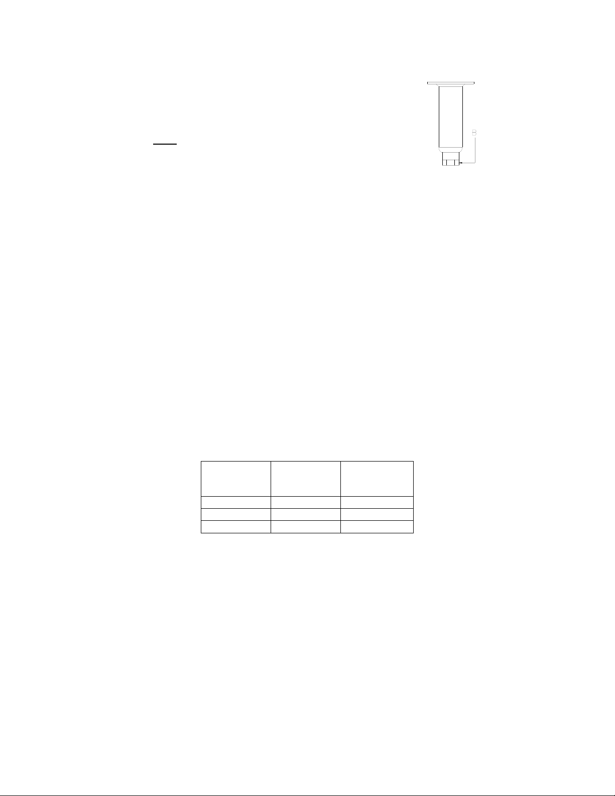
Required tools: 7/16 “ wrench and socket and a large pair of water pump pliers. The legs must be installed
before connecting the appliance to the gas supply. The legs provide the necessary height to meet sanitation
requirements and assure adequate air supply to the combustion system. Use the following procedure.
a. Lay the appliance on its back, being careful not to damage the flue area by pulling on it. Protect
the outside of the appliance with cardboard or a drop cloth when laying it down.
b. Attach each leg with the hex head screws and nuts supplied. Each leg requires four ¼-20 x 5/8”
hex head screws and nuts. Insure that all screws are tight.
c. Mount the screws from the inside of the appliance with the nut on the outside (bottom) of the
appliance. The nuts have lock washers attached to them, therefore it is not necessary to use
lock washers
d. When all four legs are securely mounted, stand the unit up, being careful not to put too much
weight on any one leg. Adjust the height and level the appliance by adjusting the leveling
devices (B) with water pump pliers.
1.1 Installation Clearances
The clearances shown below are for combustible and non-combustible installations and will allow for safe and
proper operation of your appliance.
*For use only on Non Combustible Floors. This appliance must be installed on a fireproof base.
In addition to the above clearances there must also be at least 28 inches (71 cm) of aisle space in front of the
appliance.
1.2 Gas Connection
Your appliance will give you peak performance when the gas supply line is of sufficient size to provide the
correct gas flow. The gas inlet of the appliance is located in the back of the appliance on the lower right hand
side about 21 cm from the floor. The gas line must be installed in accordance with the requirements of AS 5601
or local codes, by a qualified professional. Gas line sizing requirements can be determined by a qualified
installation professional, your local gas company or by the Technical Regulator. The gas line needs to be large
enough to supply the necessary amount of fuel to all appliances without losing pressure to any appliance. A
properly sized and installed gas line will deliver a minimum supply pressure of 7.0 ± 2.0 inches w.c. (1.75 ± 0.5
kPa/17.5± 5 mbar)) for natural gas and 12.0 ± 2.0 inches (3.0 ± 0.5 kPa/30± 5 mbar) for propane to all
appliances connected to the supply line, operating simultaneously at full demand. Each appliance is equipped to
operate on one certain fuel type. The type of fuel with which the appliance is intended to operate is stamped on
the data plate, which is attached to the inside of the door.
2
L22-348 R1 5/13
Page 5
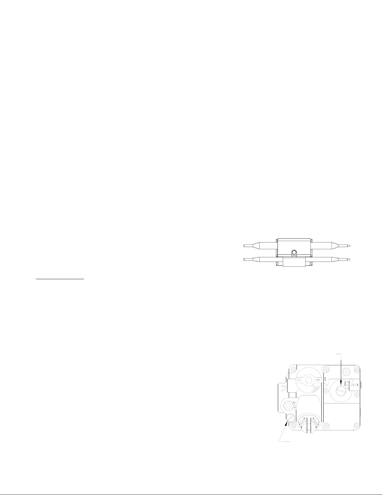
REGULATOR ADJUSTOR
(UNDER CAP SCREW)
PILOT ADJUSTOR
(UNDER CAP SCREW)
1.3 Gas Connection and Sealing Compound
As with any gas appliance, be sure to use a suitable gas joint sealant whenever gas connections are loosened
and retightened. Also remember to check for leaks before allowing the appliance to be put into service.
1.4 Fuel Supply Line Leak and Pressure Testing
The fuel supply system must be tested before the appliance is used. If the fuel line is going to be tested at a
pressure greater than ½ PISG (3.45 kPa/34.5 mbar), insure that that appliance is disconnected from the fuel
line. If the fuel line is to be tested at a pressure equal to or less than ½ PSIG (3.45 kPa/34.5 mbar), the
appliance can be connected during the test, but the unit’s gas valve must be shut. Test all gas line connections
for leaks with a solution of soap and water when pressure is applied.
2 INITIAL ADJUSTMENTS
After the appliance has been properly installed as described in the installation section of this manual, it will need
to be adjusted to ensure that it will perform as designed. These adjustments must be performed by a qualified
person. To perform these adjustments the following tools will be needed:
• Manometer • Digital Thermometer (Temperature Probe)
• DC Millivolt Meter • DC Milliameter
Before you begin filling and adjusting the appliance, perform the following visual checks:
a. After the appliance is in its permanent location, check the levelness. Any additional leveling that
is necessary can be performed as previously described.
b. Check the temperature probe and high limit bulb (in the tank) to ensure that the mounting
screws are tight.
c. Review the installation portion of this manual and ensure
that all steps have been followed and executed properly.
2.1 Pilot Flame Adjustment after gas valve replacement
For manual pilots, refer to the following instructions. Perform this procedure once the pilot is lit.
NOTE: This procedure requires a DC millivolt meter set to a scale of 0-1000 mV.
Using test leads with sharp probes will help in taking the required readings.
a. Locate the thermocouple wires coming from the thermostat/limit box going to the gas
valve. The wire size decreases near the gas valve connections.
b. Using the positive (+) test probe, connect the probe to the high limit wire terminal. On
UFM systems, pierce the high limit wire insulation, with the tip of the test lead probe, at
the gas valve safety magnet connection.
c. Connect the negative (-) test probe to the pilot tubing.
d. Remove the cap screw located below the pilot tubing on the gas
valve. The pilot flame adjustment screw is recessed behind this.
Turning the pilot flame adjustment screw clockwise
lowers the pilot flame and millivolt output. Turning the pilot flame
adjustment screw counter- clockwise increases the pilot flame size
and millivolt output.
e. While monitoring the DC millivolt meter, rotate the pilot flame
adjustment screw in the direction necessary to achieve a reading of
400 ± 50mV.
f. Replace the cap screw.
Note: Allow 3 to 5 minutes between flame adjustments to allow
the reading to stabilize.
3
L22-348 R1 5/13
Page 6
MAIN BURNER
MAIN BURNER ORIFICE
2.2 Main Burner System Adjustment
For the main burners to operate the gas supply valve must be open and the thermostat must be turned on. For
models with electric controls, the main power switch must be on. The main burners receive gas from the main
gas supply through the thermostatically controlled valve. When the thermostat is turned up to a setting higher
than the temperature of the oil in the tank, the gas control valve opens.
The main burner pressure must be adjusted to deliver optimum flame. Refer to the following procedure to adjust
the main burners.
CAUTION
Before proceeding any further, fill the tank with WATER. Water is used for the installation
adjustments because the temperature will never exceed 212°F (100°C), thereby allowing plenty of
adjustment time. Never let the water level go below the MIN LEVEL mark stamped on the tank.
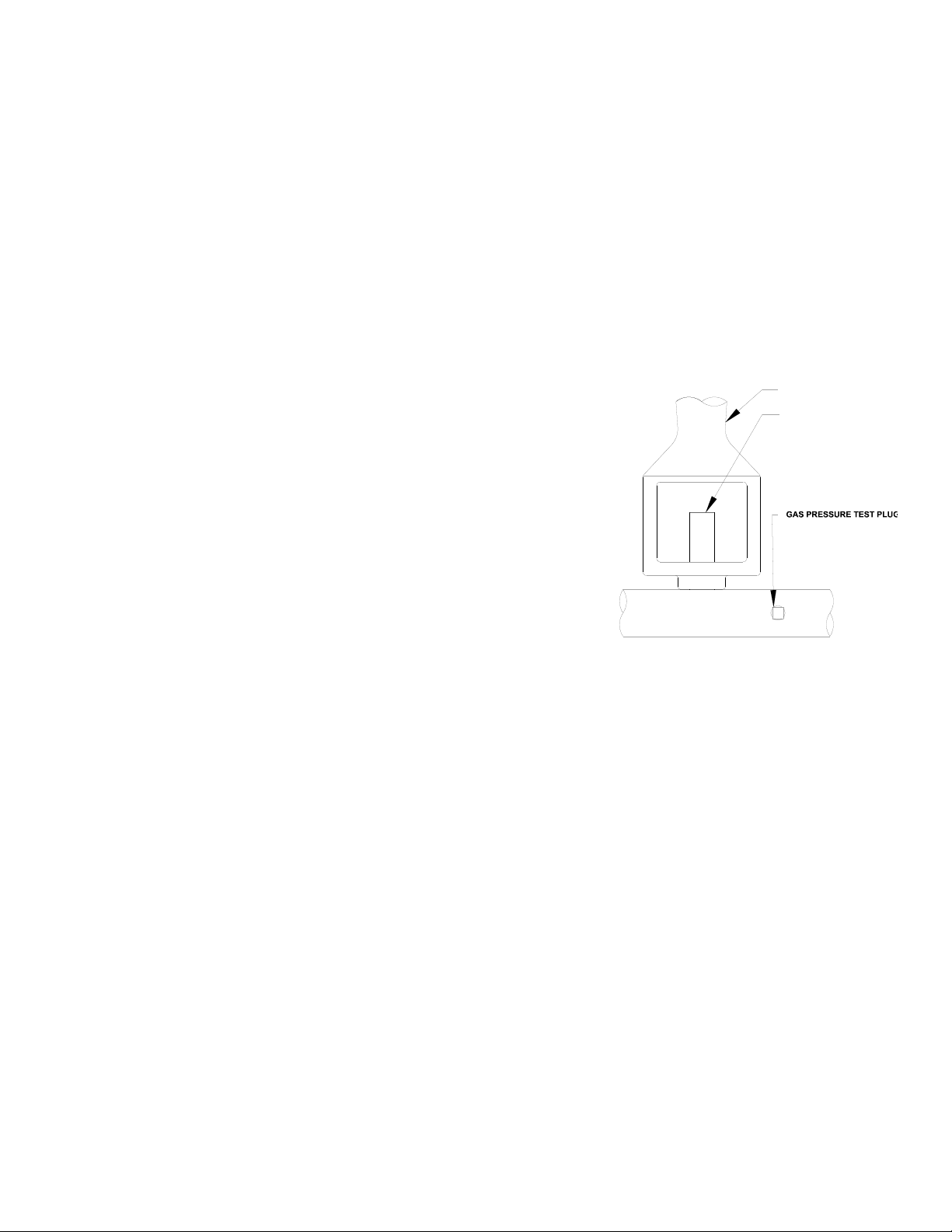
a. Ensure that the main gas valve is shut off; remove the manifold pressure tap plug and connect
an accurate pressure gauge having a range from 0 to 16 “ w.c. in 0.1” increments (0 to 4 kPa in
.025 kPa/0-40 in 0.25 mbar increments) or manometer with similar resolution.
b. Turn on this and all appliances connected to the gas supply
line and light their main burners. The pressure reading of
the installed pressure gauge should not drop from the
required installation pressure. Any loss of pressure
indicates inadequate supply line installation, which will
cause poor performance of all appliances during peak
usage.
c. The installed pressure gauge should be the same, ±0.1”
w.c. (.025 kPa/.250 mbar), as that marked on the data plate
on the inside door of the appliance. If the pressure is
correct, go to step e, if it is not, adjust the pressure as
outlined in step d.
d. To adjust the pressure, remove the regulator adjustment
screw cap on the gas valve and, with a flat head
screwdriver, adjust the regulator screw until the proper burner pressure is reached. Turning the
screw clockwise will increase the burner pressure. Turning the screw counterclockwise will
decrease the burner pressure.
e. When the pressure is correct, replace the regulator adjustment screw cover.
f. Turn off the ALL appliances, shut the main gas valve to your appliance and remove the
pressure gauge. Apply pipe joint compound to the manifold pressure tap plug and reinstall it.
3 Thermostat Calibration
NOTICE
Thermostat calibration requires that the temperature of the appliance be raised above 212°F
(100°C). If you have water in the tank you will need to drain it, dry it and fill it with shortening/oil.
Follow the filling instructions in this manual.
3.1 Thermostat Calibration Check (Standard)
To check the calibration of your appliance, refer to the following procedure.
a. Remove the tube screen from the tank.
b. Place the tip of a digital thermometer probe in the shortening/oil approximately one inch above
the temperature sensor.
c. Light the pilot as described in this manual, set the thermostat to 325°F (163 °C) and allow the
shortening/oil to come up to temperature. Watch the thermometer closely as the temperature
rises.
d. If the shortening/oil temperature reaches 350°F (177 °C) and the burners do not turn off, turn
the thermostat down. Keep lowering the thermostat setting until the burners go out.Let the
appliance cycle 4 to 6 times before checking the temperature. Compare the thermometer
temperature against the thermostat setting. If the values are more than 5°F (3 °C) apart,
calibrate the thermostat using procedure in this manual.
4
L22-348 R1 5/13
Page 7

CAUTION
If the burners do not shut off at the LOWEST thermostat setting, the thermostat may be
defective. Contact your local service company.
3.2 For Gas Operated and Electric Thermostats refer to the following procedure.
a. Remove the tube screen from the tank and place the tip of a digital thermometer in the
shortening/oil approximately one inch above the temperature sensor.
b. Light the pilot as described in this manual, set the thermostat to 325°F (163 °C) and allow the
shortening/oil to come up to temperature; let the appliance cycle 4-6 times to insure that the
shortening/oil temperature has stabilized. Compare the thermostat setting of 325°F (163 °C) to
the digital thermometer reading.
c. Remove the thermostat dial by pulling the knob straight out. DO NOT rotate the dial.
d. Holding the outside of the shaft so that it DOES NOT MOVE, scrape away the sealing
compound in the center of the shaft with a small flat blade screwdriver.
e. Turn the adjustment screw clockwise to lower the thermostat’s temperature setting or counter-
clockwise to raise it.
NOTE
One-quarter turn of the adjustment screw changes the temperature setting
approximately 24°F (13 °C).
f. Turn the adjustment screw until the burners come on at 325°F (163 °C).
g. Replace the knob and allow the appliance to cycle 4 to 6 times. Check the temperature of the
digital thermometer against the thermostat dial setting; if there is greater than a 5°F
(3 °C) difference, repeat the calibration procedure.
5
L22-348 R1 5/13
Page 8

NO
YES
YES
Appliance does not
work.
Will the
pilot
light?
NO
Is the gas
supply
valve
open?
NO
Open the gas
valve and light
pilot
Purge air from
gas line
Does pilot
stay lit after
pilot knob is
released?
YES
YES
NO
Is all the
air purged
from the
pilot gas
YES
NO
Is high
limit
switch
open?
Will high
limit switch
reset?
YES
Reset switch
and light pilot.
Contact a
qualified service
technician
NO
NO
Does pilot go
out when the
temperature
increases?
YES
Do the main
burners
light?
NO
Purge air from pilot line by
turning pilot knob to the
"PILOT" position and
holding it in for approx. 1
minute.
Is the gas
valve knob in
the "ON"
position?
Is the
thermostat
knob in the
OFF position?
NO
YES
If the main burners are
lighting, but not performing
properly refer to the
INSTALLATION section of
this manual to verify proper
installation.
Turn the gas
valve knob to
the "ON"
position.
NO
Turn the
thermostat knob
to a
temperature
4 Trouble Shooting
Refer to this section to correct common problems that may be encountered during the course of normal
operation. If applicable, a schematic is provided behind the panel containing the electrical components.
6
L22-348 R1 5/13
Page 9

IGNITOR
THERMOCOUPLE
& PILOT
GAS
VALVE
PILOT
W
W
IN
VENT
THERMOSTAT
IN
OUT
THERMOSTAT
PROBE
HIGH
LIMIT
IN
OUT
4.1 Testing the Thermocouple:
You will need a multimeter that can measure millivolts. Make sure that after holding a flame to the
thermocouple it produces 30 mv. You can test for this by heating the thermocouple for about a minute and then
place one lead on the copper casing of the thermocouple and the other lead on one of terminals of the hi limit
wire connection. This is the easiest way to check the thermocouple but you are also going on the faith that the
Radix wire and hi limit are good. If you do not get between 25 and 30 millivolts you need to replace this part,
part number is P5047540.
Stay away from any hard or sharp bends in the thermocouple. It tends to separate the wire inside the
copper casing. Another good tip is when screwing in the thermocouple always start by hand. You should get
several turns out of it before needing a wrench. Cross threading will damage the aluminum threads for the
magnet. After the thermocouple is finger tight give it a quarter turn with a wrench, no more. If all these parts
check out and the pilot still wont stay lit you need to recheck everything something there is missing.
4.2 Testing the Radix wire:
Make sure that your Radix (gas valve to hi limit) wire isn't damaged or broken. The easiest is to remove
the thermocouple from the valve, remove the Radix wire and inspect both sides of that butterfly connector. Make
sure the wires aren't broken and then check for continuity through it. If it is bad the part number is B6779850.
4.3 Testing the Hi Limit:
Press the red reset button and make sure it doesn't click. If it does, push it until it doesn't. This means
the unit overheated or the hi limit tripped early. To check the trip temp of the switch the fryer will need to be ran
at a set temp of 400°F (204°C). The limit should trip at 450°F (232°C) plus or minus 25°F (14°C) degrees.
Check for continuity through the posts to ensure that the switch is making contact. If it won't reset or it reads an
open signal you have a bad hi limit, the part number is PP10084.
One factor to look for that won't show up as a bad part is a crack in the black plastic casing of the hi
limit. This would cause a problem; it happens when the radix wire thermocouple is cross threaded or over
tightened.
4.4 Testing the Gas Valve:
With the thermocouple and Radix wire removed, take one lead of a multimeter and place it into the
center of the magnet of the valve. The magnet is the aluminum insert on the valve you screw the thermocouple
into. There is a concave landing in the center of the insert. It is insulated from the rest of the valve. Place the
other lead on the threaded part of the insert. Make sure the lead on the center landing doesn't tough anything
else or you will get an incorrect reading. You're checking resistance, and you're looking for 8 to 11 ohms. If it's
more or less you have a bad magnet inside the valve and the valve needs to be replaced.
7
L22-348 R1 5/13
Page 10

5 SLG40 Exploded Parts Diagram
8
L22-348 R1 5/13
Page 11

ITEM# PART# PART DESCRIPTION
1 B3332601 TANK,WELDMENT SLG40 (BAFFLES WELDED TO TANK)
2 B1004001 BAFFLE, WELDMENT SLG40 (SERVICE)
A1540001 CABINET SIDE, LEFT HAND SLG40 BEFORE JULY 2013
A1541101 CABINET SIDE, LEFT HAND SLG40 POST JULY 2013
A1540005 CABINET SIDE, LEFT HAND SLG40 BEFORE JULY 2013
A1541103 CABINET SIDE, LEFT HAND SLG40 POST JULY 2013
A1237801 CABINET, FRONT BOTTOM BRACE SLG40 BEFORE JULY 2013
A1861001 CABINET, FRONT BOTTOM BRACE SLG40 POST JULY 2013
A1640301 CABINET BACK, BOTTOM BRACE SLG40 BEFORE JULY 2013
A1641401 CABINET BACK, BOTTOM BRACE SLG40 POST JULY 2013
A1856901 CABINET, SPACER SLG40 BEFORE JULY 2013
A1861201 CABINET, SPACER SLG40 POST JULY 2013
8 A8048001 PIPING, BRACKET MANIFOLD REAR
9 B13811-00 FLUE, DEFLECTOR SLG40
B2306101 DOOR, ASSEMBLY SLG40 BEFORE JULY 2013
B2306301 DOOR, ASSEMBLY SLG40 POST JULY 2013
A2336502 DOOR, OUTER SLG40 BEFORE JULY 2013
A2337302 DOOR, OUTER SLG40 POST JULY 2013
A2336601 DOOR, INNER SLG40 BEFORE JULY 2013
A2337401 DOOR, INNER SLG40 POST JULY 2013
PP10752 SCREW, 10-31 X 1/2 PNH ZN
PP11006 HANDLE, DOOR RECESSED PLASTIC
D6176-00 FRONT PANEL, SLG40 BEFORE JULY 2013
A3684902 FRONT PANEL, SLG40 POST JULY 2013
12 P0091500 TINNERMAN C-12003-017 #6
13 D6180-00 SPLASH BACK, SLG40
C11020-00 FLUE, ASSEMBLY SLG40
B3506401 FLUE, ASSEMBLY SLG50
B13790-00 BURNER HOLD DOWN SLG40
A8048802 BURNER HOLD DOWN SLG50
16 A1847002 CLIP, BRACKET MAGNET CATCH
18 A1408002 BULB COVER STEPPED SLG
18 A3800603 DOOR HINGE PIN
19 E4556-04 BURNER
20 P6071300 DOOR MAGNET
21 P0020600 SCREW, 1/4-20 X 5/8 HEAX HEAD ZINC PLATED
22 B3900701 LEG, SET 6" WITH HARDWARE (SET OF 4)
23 P0093300 NUT, HEX (KEP) 1/4-20 ZINC PLATED
24 60084501 DRAIN VALVE, 1 1/4 NON-LOCKING
25 P9204-75 ANETS NAME PLATE BLACK/YELLOW
26 PP10668 NUT, 1/4-20 ACORN WITH CENTERLOCK STAINLESS
27 P0080650 WASHER, FLAT 1/4 ZINC
28 A2510101 TANK, NIPPLE DRAIN OUT 1 1/4 NPT
29 A4500601 WIRING RACK, TUBE 13.50 X 13.50
30 P9800-08 BASKETS, DOUBLE 2 PER SLG40
31 PP10023 SCREW, 10-24 X 3/8 SELF TAPPER
32 C9054-01 BASKET HANGER SLG40/50
7
14
151011
3
4
5
6
5.1 SLG40 Exploded Parts List
9
L22-348 R1 5/13
Page 12

6 SLG100 Exploded Parts Diagram
10
L22-348 R1 5/13
Page 13

ITEM# PART# PART DESCRIPTION
1 B3336301 TANK,WELDMENT SLG100 (BAFFLES WELDED TO TANK)
2 B1004002 BAFFLE, WELDMENT SLG100 (SERVICE)
A1540003 CABINET SIDE, RIGHT SIDE SLG100 BEFORE JULY 2013
A1541105 CABINET SIDE, RIGHT SIDE SLG100 POST JULY 2013
A1540007 CABINET SIDE, RIGHT SIDE SLG100 BEFORE JULY 2013
A1541107 CABINET SIDE, RIGHT SIDE SLG100 POST JULY 2013
A1237803 CABINET, FRONT BOTTOM BRACE SLG100 BEFORE JULY 2013
A1861003 CABINET, FRONT BOTTOM BRACE SLG100 POST JULY 2013
A1640303 CABINET BACK, BOTTOM BRACE SLG100 BEFORE JULY 2013
A1641403 CABINET BACK, BOTTOM BRACE SLG100 POST JULY 2013
A1857001 CABINET, SPACER SLG100 BEFORE JULY 2013
A1861203 CABINET, SPACER SLG100 POST JULY 2013
8 A8048001 PIPING, BRACKET MANIFOLD REAR
9 B14090-00 FLUE, DEFLECTOR SLG100
B2306102 DOOR, ASSEMBLY SLG100 BEFORE JULY 2013
B2306302 DOOR, ASSEMBLY SLG100 POST JULY 2013
A3636504 DOOR, OUTER SLG100 BEFORE JULY 2013
A2337304 DOOR, OUTER SLG100 POST JULY 2013
A2336603 DOOR, INNER SLG100 BEFORE JULY 2013
A2337403 DOOR, INNER SLG100 POST JULY 2013
PP10752 SCREW, 10-31 X 1/2 PNH ZN
PP11006 HANDLE, DOOR RECESSED PLASTIC
A3681802 FRONT PANEL, SLG100 BEFORE JULY 2013
A3684904 FRONT PANEL, SLG100 POST JULY 2013
12 P0091500 TINNERMAN C-12003-017 #6
13 E5192-00 SPLASH BACK, SLG100
C10880-00 FLUE, ASSEMBLY SLG100
E5190-00 FLUE BACK
D6265-00 FLUE FRONT
C10860-00 FLUE SUPPORT
15 B14052-00 BURNER HOLD DOWN SLG100
16 A1847002 CLIP, BRACKET MAGNET CATCH
18 A1408002 BULB COVER STEPPED SLG
18 A3800603 DOOR HINGE PIN
19 E4556-04 BURNER
20 P6071300 DOOR MAGNET
21 P0020600 SCREW, 1/4-20 X 5/8 HEAX HEAD ZINC PLATED
22 B3900701 LEG, SET 6" WITH HARDWARE (SET OF 4)
23 P0093300 NUT, HEX (KEP) 1/4-20 ZINC PLATED
24 60084501 DRAIN VALVE, 1 1/4 NON-LOCKING
25 P9204-75 ANETS NAME PLATE BLACK/YELLOW
26 PP10668 NUT, 1/4-20 ACORN WITH CENTERLOCK STAINLESS
27 P0080650 WASHER, FLAT 1/4 ZINC
28 A2510101 TANK, NIPPLE DRAIN OUT 1 1/4 NPT
29 P6073186 TUBE RACK
P9800-48 BASKET
P9800-56 TRIPLE BASKET
31 PP10023 SCREW, 10-24 X 3/8 SELF TAPPER
32 C9183-00 BASKET HANGER SLG100
30
1134
5
6
10
14
6.1 SLG100 Exploded Parts List
11
L22-348 R1 5/13
Page 14

7 SLG40 Gas Assembly Exploded AU & CE Diagram
12
L22-348 R1 5/13
Page 15

ITEM# PART# PART DESCRIPTION
1 A8049901 PIPING, MANIFOLD BRACKET FRONT SLG40
PP11001 GAS VALVE G20 U7000 SLG40
PP11002 GAS VALVE G31 U7000 SLG40
PP11110 GAS VALVE G20 BGOL/S UNREGULATED
3 60179801 INTERRUPTOR,MV 11/32 THREAD
4 P7037090
NIPPLE, BLACK 1/2 NPT X CLOSE
5 P7037750
ELBOW, STREET 1/2 NPT 90 DEGREE
6 P8820-91
NIPPLE, BLACK 1/2 NPT X 17"
7 P7036902
UNION BLACK 1/2 NPT
B8058801
PIPING, WELDMENT GAS MANIFOLD AU
P8841-38
PIPING, WELDMENT GAS MANIFOLD CE
9 60132801
PRESSURE TEST FITTING 1/8 NPT
10 PP10023
SCREW, 10-24 X 3/8 SELF TAPPER
P8905-04
ORIFICE, BURNER #31 NAT/G20 SLG40
A8047103
ORIFICE, BURNER 1.9mm PROPANE SLG40
P8905-16
ORIFICE, BLANK
ELEVATION CHANGE
P8905-83
ORIFICE, BURNER #34 NATURAL
A8047101
ORIFICE, BURNER 3.4mm NATURAL G25
A8047104
ORIFICE, BURNER #35 NATURAL
A8047105
ORIFICE, BURNER #36 NATURAL
A8047106
ORIFICE, BURNER #37 NATURAL
A8047107
ORIFICE, BURNER #38 NATURAL
A8047108
ORIFICE, BURNER #39 NATURAL
A8047110
ORIFICE, BURNER #33 NATURAL
P8905-84
ORIFICE, BURNER #50 PROPANE
A8047102
ORIFICE, BURNER #51 PROPANE
A8047103
ORIFICE, BURNER 1.9mm PROPANE G31
A8047109
ORIFICE, BURNER #52 PROPANE
12 60094101
BRASS STREET ELBOW 1/8 NPT
13 PP10067
METRIC GAS SUPPLY ADAPTER FITTING
60128801 PILOT REVERSE STANDING NAT
60128802 PILOT REVERSE STANDING LP
15
P0075200 SELF DRILLING SCREW 8-18 X 1/2
16 P9131-55 GAS VALVE VENT TUBE (DOMESTIC ONLY)
17 60088014
NIPPLE, BLACK 1/2 NPT X 2"
18 60119001
ELBOW, STREET 1/2 NPT 90 DEGREE
19 60125501
NIPPLE, BLACK 1/2 NPT X 17"
2
11A
11B
14
8
7.1 SLG40 Gas Assembly Exploded AU & CE Parts
13
L22-348 R1 5/13
Page 16

8 SLG100 Gas Supply Exploded AU & CE Diagram
14
L22-348 R1 5/13
Page 17

PLOT PART# PART DESCRIPTION
1 P9315-61 PIPING, WELDMENT GAS MANIFOLD SLG100
PP10955 GAS VALVE G20/G25 U7000
PP10956 GAS VALVE G31 U7000
PP11110 GAS VALVE G20 BGOL/S UNREGULATED
3 PP10067 GAS SUPPLY METRIC ADAPTER
4 P7037093
NIPPLE, BLACK 1/2 NPT X 2"
5 P7037750
ELBOW, STREET 1/2 NPT 90 DEGREE
6 P8820-91
NIPPLE, BLACK 1/2 NPT X 17"
7 P7036902
UNION BLACK 1/2 NPT
8
A8048001
GAS SUPPLY WELDMENT SUPPORT BRACKET SLG100
9 60132801
GAS MANIFOLD TEST FITTING 1/8 NPT
10 PP10023
SCREW, 10-24 X 3/8 SELF TAPPER
P8905-04
ORIFICE, BURNER #31 NATURAL SLG100
P8905-05
ORIFICE, BURNER #49 PROPANE SLG100
11A P8905-16
ORIFICE, BLANK
ELEVATION CHANGE OR CE ORIFICE TIPS
P8905-83
ORIFICE, BURNER #34 NATURAL
A8047101
ORIFICE, BURNER 3.4mm NATURAL
A8047104
ORIFICE, BURNER #35 NATURAL
A8047105
ORIFICE, BURNER #36 NATURAL
A8047106
ORIFICE, BURNER #37 NATURAL
A8047107
ORIFICE, BURNER #38 NATURAL
A8047108
ORIFICE, BURNER #39 NATURAL
A8047110
ORIFICE, BURNER #33 NATURAL
P8905-84
ORIFICE, BURNER #50 PROPANE
A8047102
ORIFICE, BURNER #51 PROPANE
A8047103
ORIFICE, BURNER 1.9mm PROPANE
A8047109
ORIFICE, BURNER #52 PROPANE
12
60125501
THERMOPILE MILLIVOLT
13
B12326-00
THERMOPILE SUPPORT WELDMENT
14
P9131-62
SPARK IGNITOR
15
P0075300
SELF DRILLER 10/16 X 5/8
C9163-00
PILOT RUNNER TUBE WELDMENT NAT SLG100
C9163-01
PILOT RUNNER TUBE WELDMENT LP SLG100
17
B12821-00
PILOT STANDOFF SPACER
P8904-98
RUNNER TUBE ORIFICE NAT #55 SLGOO
P9804-99
RUNNER TUBE ORIFICE LP #72 SLGOO
19
P8805-11
COUPLING 1/8 NPT
20
P7037797
ELBOW 1/4 COMPRESSION X 1/8 NPT
21
P8840-92
COMPRESSION TEE 1/4 TUBE
22
P7037092
NIPPLE, BLACK 1/2 NPT X 1 1/2
23
P7037096
NIPPLE, BLACK 1/2 NPT X 3 1/2
24
PP11260
FLEXIBLE TUBE 1/4 X 10
25
P9315-61
FLEXIBLE TUBE 1/4 X 12
26
60119001
FLEXIBLE TUBE 1/4 X 18
27
60094101
BRASS STREET ELBOW 1/8 NPT
28
PP10067
METRIC GAS SUPPLY ADAPTER FITTING
161811
11B
2
8.1 SLG100 Gas Supply Exploded AU & CE Parts
15
L22-348 R1 5/13
Page 18

9 TSTAT Assembly Exploded AU Diagram
16
L22-348 R1 5/13
Page 19

ITEM# PART# PART DESCRIPTION
1 PP10084 SWITCH, HI-LIMIT
2 P5047590 THERMOSTAT, GS 190C
3 B14503-00 PIPING, BRACKET THERMOSTAT WITH IGNITOR
4 PP10687 SCREW, 6-32 X 5/16 TH PHILLIPS
5
PP10539 KNOB, THERMOSTAT
6
P0007300 SCREW, 8-32 X 1/4 HEX HEAD ZINC
7
B6744402 WIRING, MILLIVOLT HI-LIMIT/THERMOSTAT
8
P9132-34 CONTROL, SPARK IGNITOR
9 60172101 BATTERY, TRIPLE A 1.5V
10 60167801 CONTROL, WIRE SPARK IGNITOR 24"
11
P9132-37 CONTROL, SPARK IGNITOR GROUND WIRE
12
P9204-18 LABEL, IGNITOR
60119001
FLEX TUBING 18" CE
A8049701 PIPING, THERMOSTAT IN-GAS VALVE-OUT SLG40 AU
A8049703 PIPING, THERMOSTAT IN-GAS VALVE-OUT SLG100 AU
A8049702 PIPING, THERMOSTAT OUT-GAS VALVE-IN SLG40 AU
A8049704 PIPING, THERMOSTAT OUT-GAS VALVE-IN SLG100 AU
13
14
9.1 TSTAT Assembly Exploded AU Parts
17
L22-348 R1 5/13
Page 20

MAILING ADDRESS – P.O. BOX 501, CONCORD, NH 03302-0501
SHIPPING ADDRESS – 10 FERRY ST., CONCORD, NH 03301
In the event of problems with or questions about
your order, please contact the Anetsberger
Factory at:
+001 (603) 225-6684 (World Wide)
In the event of problems with or questions about
your equipment, please contact the Anetsberger
Authorized Service and Parts representative
(ASAP) covering your area, or contact
Anetsberger at the number listed to the left.
18
L22-348 R1 5/13
 Loading...