

Anets GPC-20 Installation Manual
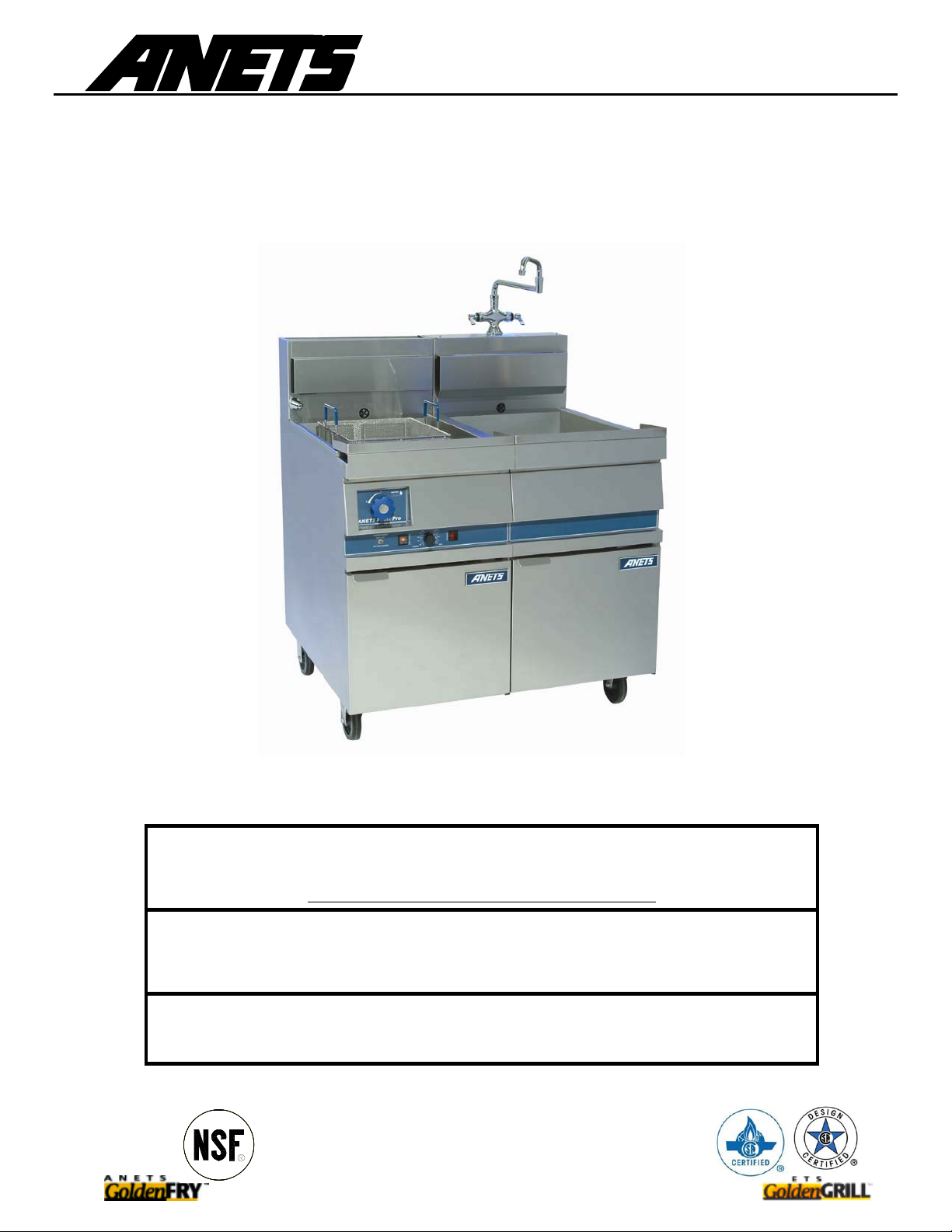
GPC-14/18/20
PASTA COOKER
GPC PASTA PRO
INSTALLATION & USER OPERATION MANUAL
GPC-18 shown with optional rinse station.
KEEP THIS MANUAL IN A CONVENIENT LOCATION FOR FUTURE REFERENCE.
Improper installation, adjustment, alteration, service or maintenance can cause property damage,
After installation of your equipment, immediately contact your local gas supplier to
obtain information as to what action to take in the event that the user smells gas.
This information must be posted in a prominent location.
injury or death.
Read the installation, operating and maint enance instructions thoroug hly
before installing or servicing this equipment
FOR YOUR SAFETY!
DO NOT store or use gasoline or other fl ammable vap ors or liquids
in the vicinity of this or any other appliance.
NOTICE!
WARNING!
Anets, Inc PO Box 501, Concord, NH 03302-0501
Tel: 603-225-6684 Fax: 603-225-5231
L20-345 Rev 3

GPC-14/18/20
PASTA COOKER
SHIPPING CONTAINER INSPECTION
1. Carefully examine the shipping container for external damage. If damage is noted, notify the delivery carrier immediately. Save all packaging
materials for claim examination.
2. If no external damage is noted, remove the unit from the shipping container and carefully examine it for damage. If damage is noted, place the
unit in a safe location so that it can be inspected.
SPECIFICATIONS
MODEL INPUT BTU/H NATURAL PROPANE NATURAL PROPANE ELECTRICAL REQUIREMENTS
GPC-14
GPC-18
GPC-20
111,000
160,000 / 80,000
MANIFOLD PRESSURE* SUPPLY PRESSURE
3-1/2
IN. W.C.
‡
10
IN. W.C.
MINIMUM
6 IN. W.C.
†
MINIMUM
11 IN. W.C.
120V, 50/60Hz SINGLE PHASE
* Measured at pressure tap on burner manifold.
† Measured at appliance input when all other gas powered equipment is operating.
.
W.C. = Inches, Water Column
‡ IN
A 115 Volt 3-pronged grounded plug is supplied with all gas units.
Refer to the inside door of the unit for the appliance wiring diagram.
LEG / CASTER INSTALLATION
1. Carefully lay cooker on its back and install legs or casters as shown in diagram A below.
2. After placing unit in installation area, adjust individual leg inserts to level cooker (so unit does not rock), by turning only the individual inserts.
Note: Appliances with casters must be secured with a restraining device to limit movement; refer to diagram B below.
Diagram A Diagram B Diagram C
Set the length of the restraining cable so
that the gas connector is not kinked when
the restraining device is fully extended.
A minimum 6-inch clearance is
required between the unit and the
site wall(s.)
GPC-14/18/20
PASTA COOKER
INSTALLATION INSTRUCTIONS
Read all Installation Instructions carefully before starting the installation.
Failure to follow instructions may result in property damage, bodily injury or death.
When this cooker is not properly installed, a fire may result.
To reduce the risk of fire, follow all installation instructions.
1
.
The installation must conform with local codes, or in the absence of local codes, with the National Fuel Gas Code ANSI Z223.1 latest edition,
CAN/CGA -B149.1 & B149.2, Natural Gas Installation Code as applicable including:
a
.
The appliance and its individual shut off valve must be disconnected from the gas supply piping system during any pressure testing of
the system at test pressures in excess of ½ psig (3.45 kPa).
b
.
The appliance must be isolated from the gas supply piping system by closing its individual manual shut-off valve during any pressure
testing of the gas supply piping system at test pressures equal to or less than ½ psig (3.45 kPa).
c
.
For units utilizing optional floor casters, the installation shall comprise of a connector that complies with the Standard for Connectors for
Moveable Gas Appliances, ANSI Z21.69, or CAN/CGA 6.16-latest edition, and a quick-disconnect device that complies with the
Standard for Quick-Disconnect Devices for Use with Gas Fuel, ANSI Z21.41 or CAN1-6.9 “latest edition.”
d
.
Adequate means must be provided to limit the movement of the unit without depending on the connector and the quick-disconnect
device or its associated piping to limit the appliance movement (when appliance is equipped with optional casters). The limiting cabl e is
supplied by the installation contractor. It is connected to the rear of the unit through the 5/16 dia. hole . The other end is attached to
the wall near the supply fitting. Refer to diagram B.
2
.
For use only in non-combustible locations. Keep the appliance area free and clear from combustibles. Suitable for installation on noncombustible floors only.
3
.
The area that the unit is installed into should have provisions for an adequate air supply for proper burner operation and the flow of
combustion and ventilation air must not be obstructed. The bottom and back of the unit must be kept open so that the burners will be able to
draw enough air for proper operation. The area directly in front of the unit must be kept open so that the unit can be serviced.
4
.
The appliance must be installed under a vent or exhaust hood to exhaust the cooking smoke and fumes and the products of combustion in
accordance with the Standard for Ventilation Control and Fire Protection of Commercial Cooking Operations, NFPA 96.
5
.
The unit must be installed with the proper clearances to combustible materials; refer to diagram C.
IMPORTANT!
DANGER!
6
.
Make sure the unit’s pilot safety valve(s) are in the “OFF” position and turn on the main gas supply. Check for gas leaks using a soap
solution.
7
.
Restrain the unit to prevent tipping when installed in order to avoid the splashing of hot liquid. The means of restraint may be the manner of
installation, such as connection to a battery of appliances, or installed in an alcove, or by separate means, such as adequate ties.
8
.
This appliance is equipped with a 3-prong (grounding) plug and must be plugged into a properly grounded three-prong receptacle.
grounding must comply with local codes, or in the absence of local codes, with the National Electrical Code ANSI/NFPA No. 70, or the
Canadian Electrical Code, CSA C22.2, as applicable.
9
.
Cooker drain termin ates at drain valve. Connect plumbing per local and national codes.
10
.
After completion of proper hook-up and installation according to code, the unit may be operated.
NOTE:
The installer should contact local building or fire officials concerning any installation restrictions or the need for inspection of the cooke r
installation.
DO NOT pack required air spaces with insulation or other material.
NOTICE!
Electrical
 Loading...