

Anets 14GS-CS Installation Manual
IMPORTANT FOR FUTURE REFERENCE
Please complete this information and retain this manual
for the life of the equipment:
Model #: __________________________
Serial #: __________________________
Date Purchased: ___________________
Installation and Operation Manual
Covering Model Series
14GS-CS
AUSTRALIA
L20-405 Rev 4

THIS MANUAL MUST BE RETAINED FOR FUTURE REFERENCE
FOR YOUR SAFETY
DO NOT store or use gasoline or other flammable vapors or liquids in the vicinity of
this or any other appliance. Do not spray aerosols in the vicinity of this appliance while
it is in operation.
WARNING
Improper installation, alteration, service or maintenance can cause property damage,
injury or death. Read the installation, operating and maintenance instructions
thoroughly before installing or servicing this equipment.
TO THE PURCHASER
Post, in a prominent location, the
instructions to be followed in the event that
an operator smells gas. Obtain this
information from your local gas supplier.
WARNING
There is an open flame inside this appliance.
The unit may get hot enough to set nearby
materials on fire. Keep the area around the
appliance free from combustibles.
WARNING
DO NOT supply the appliance with a gas
that is not indicated on the data plate. If you
need to convert the appliance to another
type of fuel, contact your dealer.
WARNING
DO NOT use an open flame to check for
gas leaks!
WARNING
If gas flow to appliance is interrupted, or pilots
extinguish, wait 5 minutes before attempting to
relight the pilot to allow any residual gas in
appliance to dissipate.
WARNING
Ensure that the appliance can get enough air to
keep the flame burning correctly. If the flame is
starved for air, it can give off a dangerous carbon
monoxide gas. Carbon monoxide is a clear
odorless gas that can cause suffocation.
WARNING
Adequate means must be provided to limit the
movement of this appliance without depending on
the gas line connection. Single appliances
equipped with legs must be stabilized by installing
anchor straps. All appliances equipped with
casters must be stabilized by installing restraining
chains. If a flexible gas line is used, an additional
restraining cable must be connected at all times
when the appliance is in use.
WARNING
An appliance equipped with casters and a flexible
gas line must be connected to the gas supply with
a quick disconnect device. This quick disconnect
must comply with AS4631. To limit the movement
of the appliance without depending on the
connector or quick disconnect, a restraining cable
must also be installed.
WARNING
Installation of this appliance must be done by a
qualified professional. This appliance should be
inspected by a qualified professional on an annual
basis to insure safe and proper operation.
WARNING
This appliance must be installed in compliance
with AS 5601 (current revision) or local codes, as
applicable.
WARNING
If the appliance has a power supply, it must be
disconnected before servicing or cleaning this
appliance.
WARNING
Do not attempt to move this appliance when the
unit is at operating temperature. Serious personal
injury could result if skin comes in contact with the
hot surfaces.
WARNING
DO NOT sit or stand on this appliance. Serious
injury could result from falling or contact with hot
shortening/oil.
L20-405 Rev 4

Table of Contents
Section Page
Installation
Assembly and Leveling
Leg Installation and Adjustment . . . . . . . . . . . . . . . . . . . . . . . . . . . . . . . . 1
Heat Deflector Installation . . . . . . . . . . . . . . . . . . . . . . . . . . . . . . . . . 2
Installation Clearances . . . . . . . . . . . . . . . . . . . . . . . . . . . . . . . . . . . 2
Gas Connection . . . . . . . . . . . . . . . . . . . . . . . . . . . . . . . . . . . . . . . . . 2
Quick Disconnect Gas Connection . . . . . . . . . . . . . . . . . . . . . . . . . . . 3
Fuel Supply Line Leak and Pressure Testing . . . . . . . . . . . . . . . . . . . 3
Ventilation and Fire Safety Systems . . . . . . . . . . . . . . . . . . . . . . . . . . 3
Initial Adjustments
Burner Ignition Systems . . . . . . . . . . . . . . . . . . . . . . . . . . . . . . . . . . . . 4
Lighting Instructions . . . . . . . . . . . . . . . . . . . . . . . . . . . . . . . . . . . . . . . 4
Pilot Flame Adjustment . . . . . . . . . . . . . . . . . . . . . . . . . . . . . . . . . . . . . 5
Main Burner System Adjustment . . . . . . . . . . . . . . . . . . . . . . . . . . . . . . 5
Initial Cleaning . . . . . . . . . . . . . . . . . . . . . . . . . . . . . . . . . . . . . . . . . . . . 6
Operation
Filling the Tank
Filling the Tank with Liquid Shortening/oil . . . . . . . . . . . . . . . . . . . . . . . . . . 7
Filling the Tank with Solid Shortening/oil . . . . . . . . . . . . . . . . . . . . . . . . . . . 7
Operating Instructions
Appliance Start-Up . . . . . . . . . . . . . . . . . . . . . . . . . . . . . . . . . . . . . . . . . . 8
Appliance Shut-Down . . . . . . . . . . . . . . . . . . . . . . . . . . . . . . . . . . . . . . . . 8
Power Failure . . . . . . . . . . . . . . . . . . . . . . . . . . . . . . . . . . . . . . . . . . . . . . 8
Maintenance and Adjustments
Thermostat Calibration
Thermostat Calibration Check (Standard) . . . . . . . . . . . . . . . . . . . . . . . . 9
Thermostat Calibration (Gas and Electric Thermostat Models) . . . . . . . . 9
Weekly Cleaning
General Cleaning . . . . . . . . . . . . . . . . . . . . . . . . . . . . . . . . . . . . . . . . . . . 10
Weekly Boil Out Procedure . . . . . . . . . . . . . . . . . . . . . . . . . . . . . . . . . . . . 10
Ventilation Hood Maintenance . . . . . . . . . . . . . . . . . . . . . . . . . . . . . . . . . 11
Oil Temperature Notice . . . . . . . . . . . . . . . . . . . . . . . . . . . . . . . . . . . . . . . 11
Troubleshooting
Basic Troubleshooting Flow Chart . . . . . . . . . . . . . . . . . . . . . . . . . . . . . . . . . . . . 12
Conversion Procedure . . . . . . . . . . . . . . . . . . . . . . . . . . . . . . . . . . . . . . . . . . . . 13
Checking your new Appliance . . . . . . . . . . . . . . . . . . . . . . . . . . . . . . . . . . . 1
Daily Cleaning . . . . . . . . . . . . . . . . . . . . . . . . . . . . . . . . . . . . . . . . . . . . . . . . . . . . 9
Additional Maintenance and Notices
Gas Sealant Notice . . . . . . . . . . . . . . . . . . . . . . . . . . . . . . . . . . . . . . . . . . 11
L20-405 Rev 4

INSTALLATION
CHECKING YOUR NEW APPLIANCE
Your new appliance has been carefully packed into one crate. Every effort has been made to ensure that you it
is delivered to you in perfect condition. As you unpack your new appliance, inspect each of the pieces for
damage. If something is damaged, DO NOT sign the bill of lading. Contact the shipper immediately; the shipper
is only responsible for 15 days after delivery. Check the packing list enclosed with your appliance to ensure that
you have received all the parts to the appliance. If you are missing any parts, contact the dealer from whom the
appliance was purchased. As you unpack the appliance and its accessories be careful to keep the weight of the
appliance evenly distributed.
CAUTION
To prevent equipment damage and/or personal injury, do not tilt the appliance onto any
two of its legs, or pull the appliance by the flue vent.
ASSEMBLY
When you receive your appliance it is completely assembled with the possible exception of the legs and heat
deflector.
Leg Installation and Leveling
This appliance must be installed with legs; it cannot be curb mounted. Curb mounting
will seriously inhibit this appliances ability to effect proper combustion.
WARNING
This appliance must be installed with the legs provided
by the manufacturer.
WARNING
Do not install legs or perform leveling procedure when unit is in operation or full of
cooking medium. Serious injury could result.
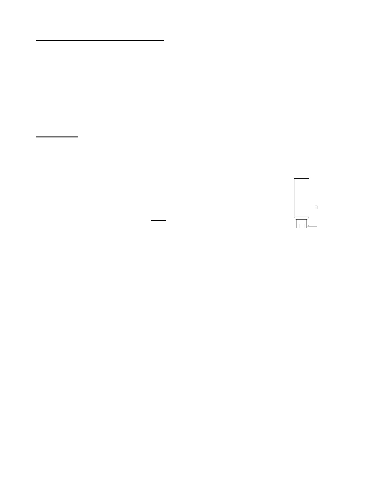
Required tools: 7/16 “ wrench and socket and a large pair of water pump pliers. The legs must be installed
before connecting the appliance to the gas supply. The legs provide the necessary height to meet sanitation
requirements and assure adequate air supply to the combustion system. Use the following procedure.
a. Lay the appliance on its back, being careful not to damage the flue area by pulling on it. Protect
b. Attach each leg with the hex head screws and nuts supplied. Each leg requires four ¼-20 x 5/8”
c. Mount the screws from the inside of the appliance with the nut on the outside (bottom) of the
d. When all four legs are securely mounted, stand the unit up, being careful not to put too much
the outside of the appliance with cardboard or a drop cloth when laying it down.
hex head screws and nuts. Insure that all screws are tight.
appliance. The nuts have lock washers attached to them, therefore it is not necessary to use
lock washers
weight on any one leg. Adjust the height and level the appliance by adjusting the leveling
devices (B) with water pump pliers.
1 L20-405 Rev 4

INSTALLATION
Heat Deflector Installation
If the appliance requires a heat deflector, you will find a removable label at the rear top edge of the unit. This
label has instructions for positioning and installation of the heat deflector. Refer to the label and the instructions
below to install the deflector.
a. Remove the two self-drilling screws from the top, back area of the appliance.
b. Position the heat deflector so that the deflector is positioned above the top surface of the flue.
Secure the heat deflector to the back of the unit using the two previously removed fasteners.
c. When properly installed the heat deflector it will extend over the flue opening to redirect the heat. It
SHOULD NOT cover the flue opening. Never allow anything to block the flue opening; this will cause
the appliance to over heat and inhibit proper combustion, which could produce dangerous gases
INSTALLATION
If you have completed the above steps that are applicable to the appliance you purchased, the appliance is now
ready to be installed. The appliance must be installed by a qualified professional. A qualified professional will
ensure that the installation is safe and meets local building and fire codes and the installation code in force.
WARNING
DO NOT obstruct the flow of combustion, ventilation or air openings around the appliance.
Adequate clearance around the appliance is necessary for servicing and proper burner
operation. Ensure that you meet the minimum clearance requirements specified in this
manual.
Overall dimension: Length: 31.75” (80.7 cm), Width: 15.63” (39.7 cm), Height: 45.5” (115.6 cm)
Weight: 178 lbs (81 kg)
Installation Clearances
The clearances shown below are for combustible and non-combustible installations and will allow for safe and
proper operation of your appliance.
Combustible
Construction
Back 6 in. (15 cm) 6 in. (15 cm)
Sides 6 in. (15 cm) 6 in. (15 cm)
Floor N/A* 4 ¾ (11.5 cm)
*For use only on Non Combustible Floors. This appliance
must be installed on a fireproof base.
In addition to the above clearances there must also be at least 28 inches (71 cm) of aisle space in front of the
appliance.
Gas Connection
Your appliance will give you peak performance when the gas supply line is of sufficient size to provide the
correct gas flow. The gas inlet of the appliance is located in the back of the appliance on the lower right about
18 cm from the floor. The gas line must be installed in accordance with the requirements of AS 5601 or local
codes, by a qualified professional. Gas line sizing requirements can be determined by a qualified installation
professional, your local gas company or by the Technical Regulator. The gas line needs to be large enough to
supply the necessary amount of fuel to all appliances without losing pressure to any appliance. A properly sized
and installed gas line will deliver a minimum supply pressure of 7.0 ± 2.0 inches w.c. (1.75 ± 0.5 kPa) for natural
gas and 12.0 ± 2.0 inches (3.0 ± 0.5 kPa) for propane to all appliances connected to the supply line, operating
simultaneously at full demand. If the delivery pressure of the gas exceeds ½ PSIG it will be necessary to install
a pressure regulator on the inlet of the appliance. If this is the case, contact the appliance supplier or authorized
service company to provide and install the proper regulator. Each appliance is equipped to operate on one
certain fuel type. The type of fuel with which the appliance is intended to operate is stamped on the data plate,
which is attached to the inside of the door.
NonCombustible
Construction
L20-405 Rev 4 2
 Loading...