

Anets 14G Installation Manual
Anets Inc.
!
!
Mailing Address: P.O. Box 501, Concord,NH 03302-0501 USA Telephone: 603-225-6684
Shipping Address: 10 Ferry Street, Concord, NH 03301 USA
www.anets.com
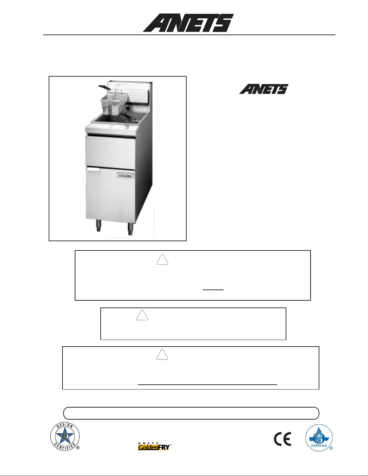
FRYER
Models
14G, 14GS
14GS shown on standard 6” legs
Improper installation, adjustment, alteration, service, or maintenance can
cause property damage, injury or death. Read the installation, operating
and maintenance instructions thoroughly before installing or servicing this
equipment.
DO NOT store or use gasoline or other flammable vapors
or liquids in the vicinity of this or any other appliance.
DANGER
FOR YOUR SAFETY
!
14GU, 14GSU,
MX-14EG, MX-14EGU
Installation,
User Operation,
&
Maintenance
Manual
WARNING
After installation of this equipment, immediately contact your local gas
supplier to obtain information about what action to take whenever any
person smells gas. Post this information in a prominent location.
Keep this Manual in a Convenient Location for Reference
The Anets Golden Line
Quality Equipment For The Restaurant, Supermarket, and Bakery Industries
L20-362 rev 3
1

DANGER
!
Read these specifications, Code Requirements, Installation Requirements, Installation
Instructions, and Operating Instructions very carefully. Failure to follow the
could cause the fryer to malfunction. A fryer malfunction can result in
serious bodily injury, or death.
CONTENTS
property damage,
Instructions
Shipping Container Inspection
Fryer Gas Supply Specifications
Fry er E lect ric al S peci fic atio ns .......................................................
Figure 1 - Fry er Mode l 14GS W i ring Dia gram .......................
Cod e Req uire ment s ......................................................................
Figure 2 - Fr yer Si te Inst allat ion Req uirem ents .......................
In sta lla tio n Re qu ire men ts ...............................................................
In sta lla tio n Ins tru cti ons ..................................................................
Le g Ins tal lat ion I nst ruc tio ns .....................................................
Le g Le vel ing Ins tr uct ion s .........................................................
Figure 3 - Typica l Leg In stalla tion .........................................
Cas ter Inst alla tio n Ins tru ctio ns .................................................
Figure 4 - T ypica l Caste r Insta llatio n .....................................
Cas ter Leve lin g In stru ctio ns ....................................................
Fryer Restraining Device Installation Instructions
Gas Connection Instructions
Fry er Op erati ng In stru ctio ns ........................................................ 11
........................................................ 3
..................................................... 4
....................... 9
........................................................
10
4
4
5
6
6
7
7
7
7
8
8
8
Frye r Prep arati on For Use (“ Boil O ut” In struc tions) ..............
Figure 5 - Draining The Kettle .............................................
Lighting Procedure
Figure 6 - Gas Saf ety Valve & Cont rol Knob Posi tions ........
Shut down P roced ure ............................................................
Food Product Frying Time Chart
Dai ly Cle anin g Pr oce dure ....................................................... 16
Monthly Maintenance Instructions
Fryer Troubleshooting Guide
Fryer W arranty
2
............................................................................ 23
................................................................
................................... ......... 15
.............................. ............ 17
.................................................
12
12
13
13
14
18 - 22
SHlPPlNG CONTAlNER lNSPECTlON
1
. Carefully examine the shipping carton for
external damage. When damage is noted, notify
the delivery carrier imm ediately . Save all packing
materials for damage claim examination.
2
. If no external damage is noted, remove the
shipping carton from the fryer and examine the
Models Covered By This Manual
Model Features Model Features
14G
14GU
14GS
14GSU
Plain Steel Fryer Kettle
Plain Steel Fryer Kettle, CE version
Stainless Steel Fryer Kettle
Stainless Steel Fryer Kettle, CE version
fryer carefully for damage. Place the fryer in a
safe location, if damage is noted, so that the freight
damage claims adjuster can examine the fryer.
3
. Save the shipping container for use during leg/
caster installation. Refer to the Installation Instructions for that procedure.
MX-14EG
MX-14EGU
High Efficiency Fryer
High Efficie ncy Fryer, CE vers ion
Standard Accessories
furnished in the shipping carton for this fryer include:
2 Fryer Baskets 1 Drain V alve Extension 1 Screen
4 Adjustable L egs 1 Cleanout Rod 1 Basket Hanger
Other optional equip ment includes a sediment tray; single or triple baskets; a built-in Filtronic™ II or Filter
Mate under-fryer filter system; a fryer cover; a drain table; a front drain tray; or four casters.
Note: A Parts List for each Anets fryer is among th eitems shipped with each fryer. If an
additional copy of this list is needed please contact the factory as directed on the back
cover.
3
FRYER GAS SUPPLY SPEClFlCATlONS
-
Please make sure that Vour desired frVer location has gas
are suitable for this product:
INPUT REQUIRED:
111,000 BTU *
MANIFOLD PRESSURE
Natural Gas Propane
3½“ W.C.
**
10“ W.C.
SUPPLY PRESSURE***
6“ W.C., minimum 11“ W.C., minimum
* -
BTU/Hr Rating is based on sea level operation. For sites above 2000 feet, reduce this
rating 4% for each 1000 feet above sea level.
** -
“W.C. = Inches, Water Column.
***
Measure Supply Pressure when all other gas-powered equipment is operating.
Gas Supply Inlet Pipe size must be ¾“ NPT
(National Pipe Thread) standard gas line. The gas
supply inlet line should be as straight as possible
(fewest bends or elbows) to obtain the highest
available gas pressure at the fryer . Locate this
inlet line horizontally at the center of the desired
fryer location, 8¼“ above the floor.
NOTE: Using a flexible inlet line permits variation
in the gas supply line location, both horizontally and
vertically .
Anets fryers are only for use with the type of gas
specified on the spec plate. if a fryer requires
modification to use a gas other than th at which is
identified on the fryer spec plate, contact you Anets
representative or call 1-603-225-6684.
supplV factors that
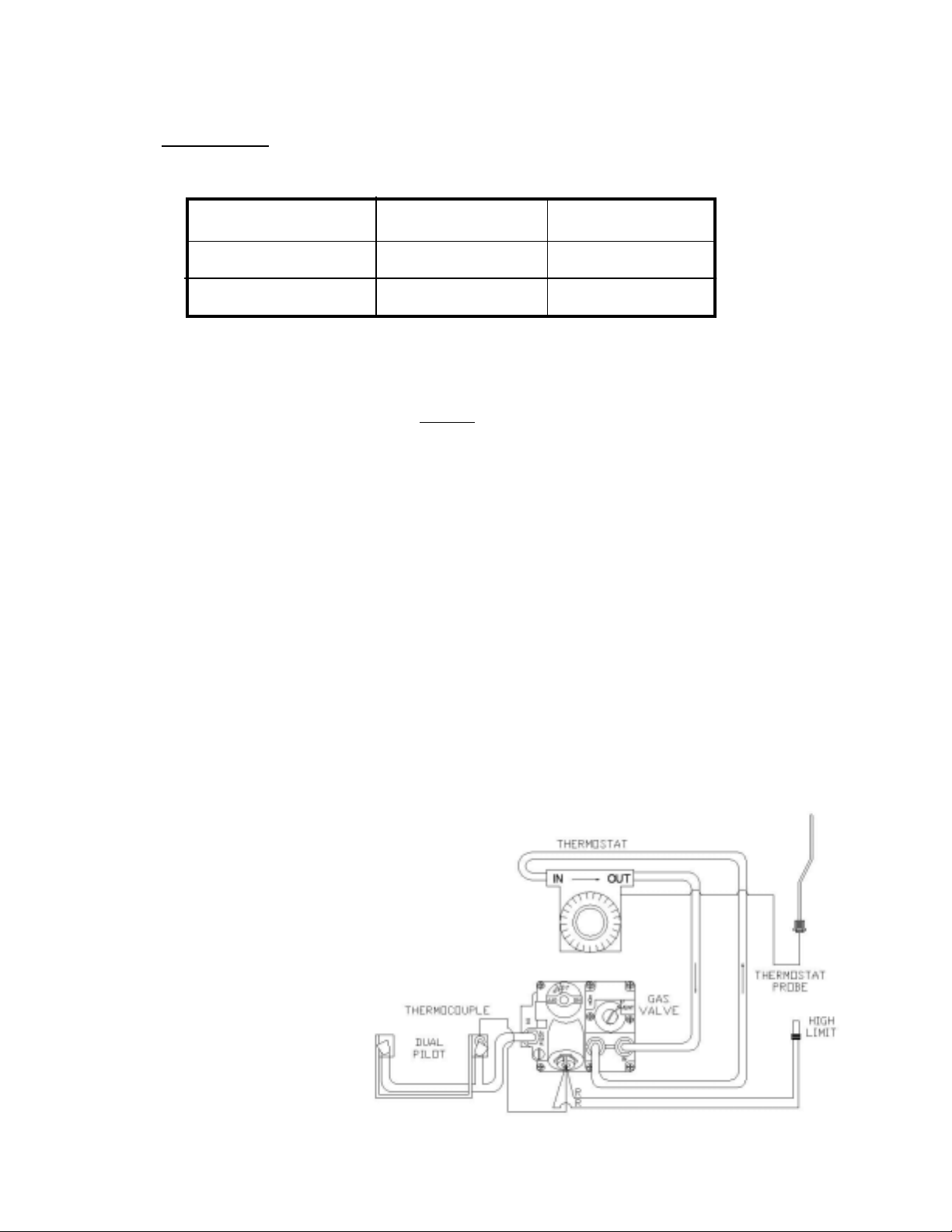
FRYER ELECTRlCAL
The
ANETS
electric power source.
Figure 1 is a wiring diagram of an
ANETS
may have other options that do not
appear in this basic wiring diagram. A
model-specific wiring diagram included
with each fryer shows all the actual parts
and their associated wiring connections.
In addition, a fryer equipped with a builtin filter sys- tem (Filtronic II or Filter
Mate) has a supplementary manual
included for that option.
Fryer Models 14GS, 14GSU, MX-14EG, and MX-14EGU require no exter-
14GS Fryer. Some fryers
SPEClFlCATlONS
nal
Figure 1. Fryer Model 14GS Wiring Diagram
4
CODE REQUlREMENTS
lMPORTANT:
and ALL installation instructions carefully ,
before starting the installation. Contact the
factory if any problems or questions arise.
The fryer installation must conform with local
codes, or in the absence of local codes, with the
National Fuel Gas Code, ANSI Z223.1 (latest
edition); the Natural Gas Installation Code, CAN/
CGA-B149.1 (latest edition); or the Propane Gas
Installation Code, CAN/CGA-B149.2 (latest
edition), as applicable, including:
a
. Disconnect the fryer and its individual shutoff
valve from the gas supply piping system during
any pressure testing of the gas supply system at
test pressures in excess of ½ psig (3.45 kPa).
b.
Isolate the fryer from the gas supply piping
system during any pressure testing of the gas
supply system at test pressures equal to or
less than ½ psig (3.45 kPa).
c
. For fryers utilizing floor casters, the fryer instal-
lation shall comprise a connec tor that complies
with the Standard for Connectors for Movable Gas Appliances, ANSI Z21.69 (latest
edition) or CAN/CGA 6.16 (latest edition),
and a quick-disconnect device that complies
with the Standard for Qui ck-Disconnect
Devices for Use with Gas Fuel, ANSI Z21.41
or CAN/CGA 1-6.9 (latest edition).
Read the Code Requirements
d.
Restrict the movement of a caster-equipped
fryer by using a limiting device (for example, a
cable attached both to the fryer and to a fixture
attached to the site structure) to avoid depending on the connector and the quick-disconnect
device or its associated piping to limit fryer
movement.
e
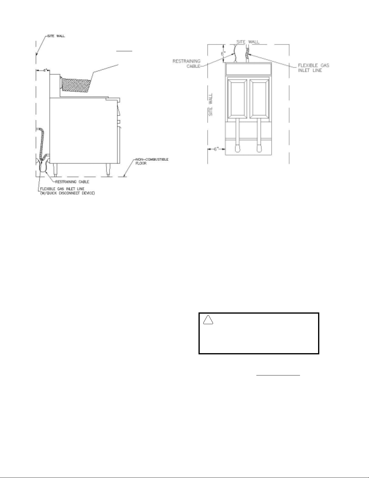
. Install this fryer on a non-combustible floor
with its back and sides at least 6” away from
any combustible wall, as shown in Figure 2.
Install this fryer under a ventilation
hood that conducts combustion products outside the building. Venting
must comply with ANSI/NFPA 96
(latest edition).
f . Install this fryer in a location where adequate
combustion and ventilation air is available.
Keep the area directly in front of the fryer open
for adequate air flow to the burners. DO
NOT obstruct the flow of combustion and
ventilation air .
g . Keep the fryer area free and clear from
combustibles and debris.
h. Attach a restraining device to each fryer, to
prevent the unit from tipping, which could
cause splashing of hot liquid.
WARNlNG
!
From the top of the flue on
r
m
e
n
d l
l
ing in
!
r
t
w
ntroldama
g
the fryer, allow a minimum
of at least 10 inches vertical clearance beneath a
Figure 2. Fryer Site Installation R equirements
ventilating hood.
lNSTALLATlON
Install the fryer in accordance with the preceding
Code Requirements, as well as the following
Installation Requirements.
1.
DO NOT install this fryer in a mobile home,
trailer, or recreational vehicle.
Install this fryer in a location that allows it to be
2.
moved away from other adjacent appliances
for cleaning and maintenance.
NOTE: If the fryer is installed among
a row of appliances (“banked”) where
its only convenient movem ent is forward, sufficient room must be available in front to permit its separation
from adjacent appliances for cleaning
and maintenance.
REQUlREMENTS
tom of the fryer using the supplied hardware, to
prevent the fryer from tipping, wobbling or
rocking when it is in its d esired location. Refer
to the following Installation Instructions for leg
casterattach
o
CAUTlON:
MUST NOT flow in a manner tha
restricts or impedes the natura l flo
of combustion or ventilation air .
4. Confirm that the air from the ventilation hood
flowing near the fryer after installation is NOT
blowing on the rear of the fryer, to prevent
affecting the burner flames and possibly causing
co
nta
eve
Hood make-up ai
e.
formation.
3. Tightly fasten the legs (or casters) to the bot-
6
lNSTALLATlON
lNSTRUCTlONS
LEG INSTALLATION
INSTRUCTIONS
1.
Flatten the shipping carton (after unpacking the
fryer and its parts and accessories) for surface
protection during leg installation.
2. Position the side of the fryer flat on the carton,
exposing the fryer bottom mounting brackets
for leg installation, as shown in Figure 3.
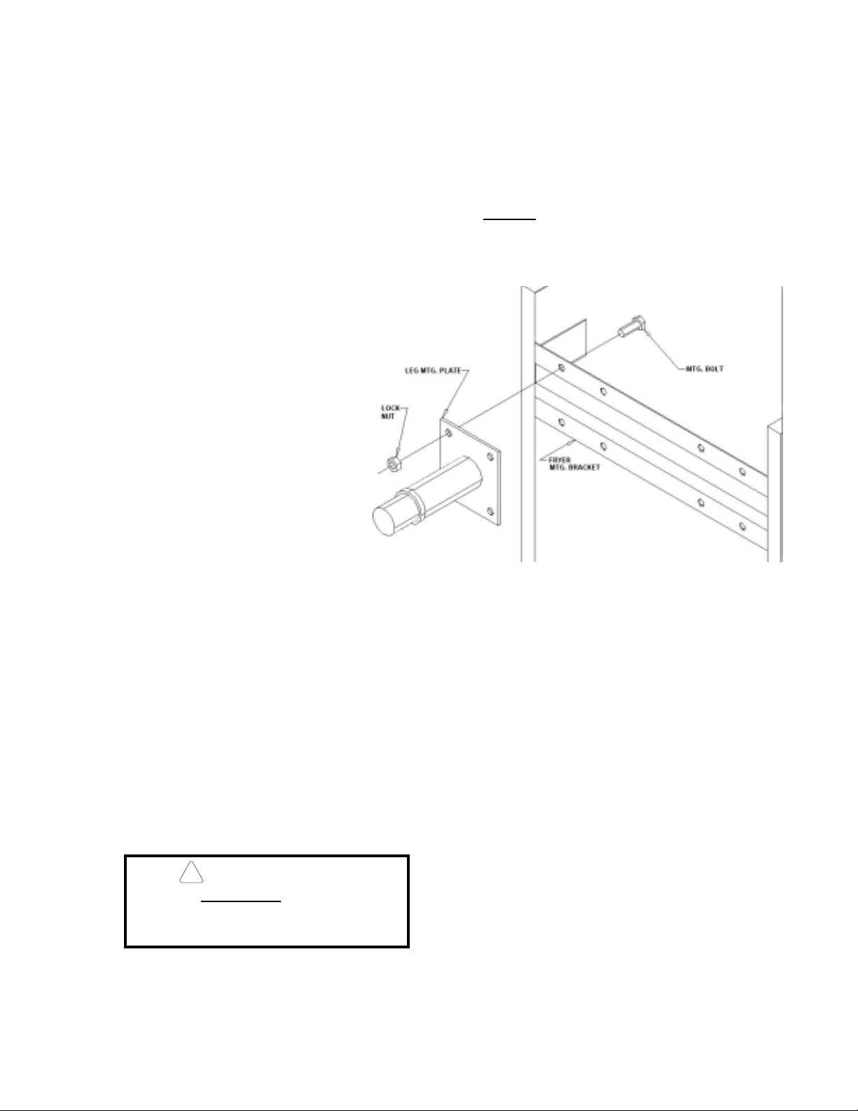
3.
Place the leg mounting plate flush against the
mounting bracket on the fryer bottom.
4.
Insert one mounting bol t through a flat
washer and then through the proper
hole in the fryer m ounting bracket
and through the leg mounting plate.
5.
Screw a locking nut several tur ns
onto the mounting bolt.
6. Repeat steps 4 and 5 until all four
mounting bolts for a leg are in place
with locking nuts.
LEG LEVELING INSTRUCTIONS
1.
Move the fryer to its desired location.
WARNlNG
!
The fryer MUST NOT tip, rock or wobble, to avoid splashing or spilling its HOT
frying fat contents during operation.
LEG INSTALLATION
INSTRUCTIONS
7. Tighten the four locking nuts evenly and
securely to hold the leg mounting plate against
the fryer mounting bracket.
Figure 3. Typical Leg Installation
2.
Turn the screw-type leg adjustment ends as
necessary to level the fryer , until no tipping,
rocking, or wobbling is evident.
3.
Perform the “Fryer Restraining Device
Installation Instructions.”
(Continued)
7
lNSTALLATlON lNSTRUCTlONS
p
!
CASTER INSTALLATION
INSTRUCTIONS
1. Flatten the shipping carton
(after unpacking the fryer and
its parts and accessories) for
surface protection during leg
installation.
2.
Position the side of the fryer flat
on the carton, exposing the
fryer bottom mounting brackets
for caster installation, as shown
in Figure 4.
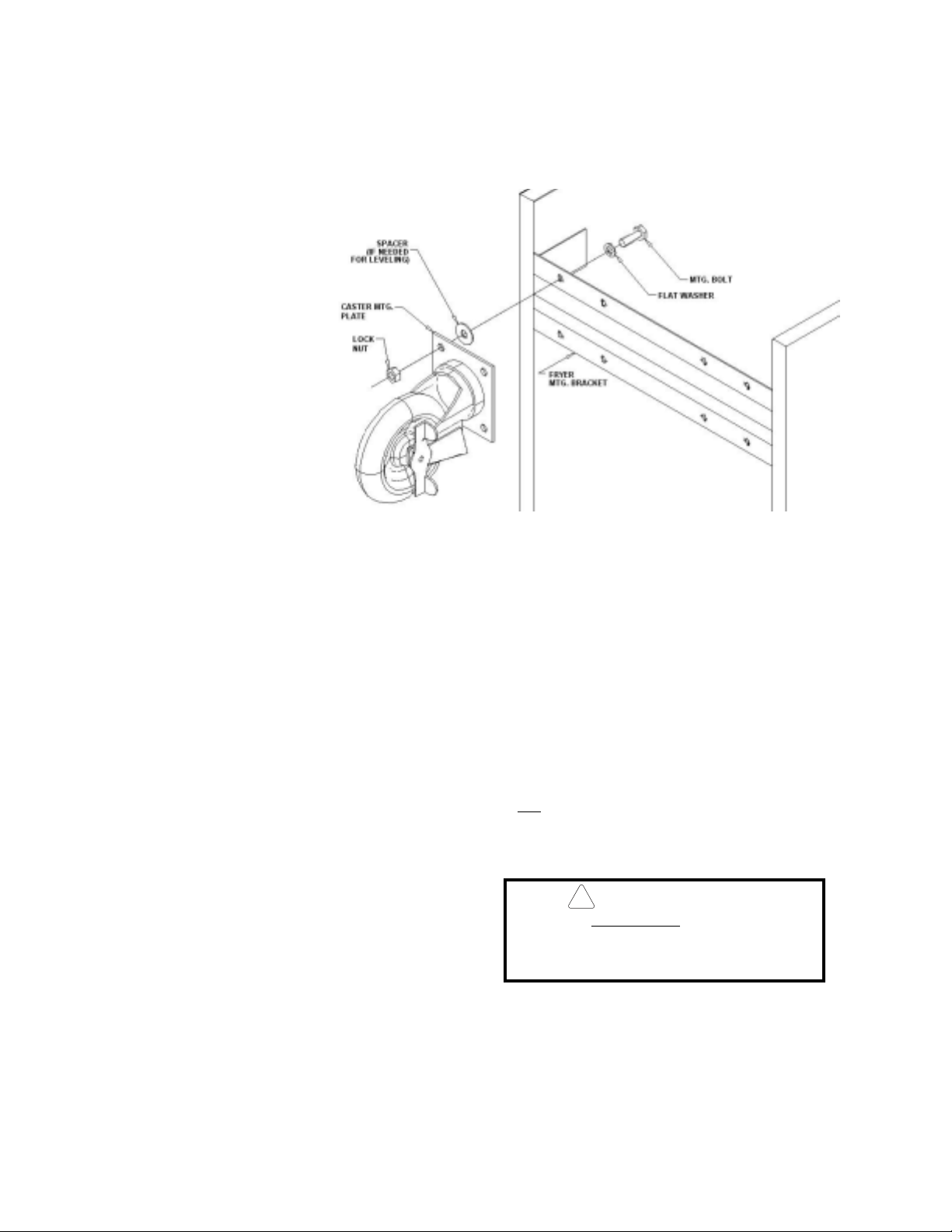
3. Place the caster mounting plate
flush against the mounting bracket on the fryer bottom.
4. Insert one mounting bolt
through a flatwasher (supplied) and the caster mounting
plate, then through the proper
hole in the fryer bottom mounting bracket.
5.
Screw a locking nut several turns onto the
mounting bolt.
(Continued)
Figure 4. Typical Caster Installation
CASTER LEVELING INSTRUCTIONS
6.
Repeat steps 4 and 5 until all four mounting
bolts for a caster are in place with locking nuts.
7. Tighten the four bolts evenly and securely to
hold the caster mounting p late against the fryer
mounting bracket.
8
1
. Move the fryer to its desired location.
2
. Determine whether the fryer t ends to wobble
or rock when in its desired location. If it does
not, perform step 10, then proceed to the
Fryer Operating Instructio ns. If it does,
erformsteps3through 9.
WARNlNG
The fryer MUST NOT tip, rock or wobble, to avoid splashing or spilling its HOT
shortening contents during operation.
3
. Determine which cas ter requires adjustment
and the approximate amount of change
required to level the fryer.
4
. Position the rear side of the fryer on the ship-
ping carton, exposing the bottom of the fryer
with the caster mounting plates (Figure 4).
 Loading...