

Anets 14ESFF User Manual
Anetsberger Br others, Inc.
180 North Anets Drive • Northbrook, Illinois 60062 • 847-272-0770 • Fax 847-272-1943
For ANETS Factory Warranty Service • 800-837-2638
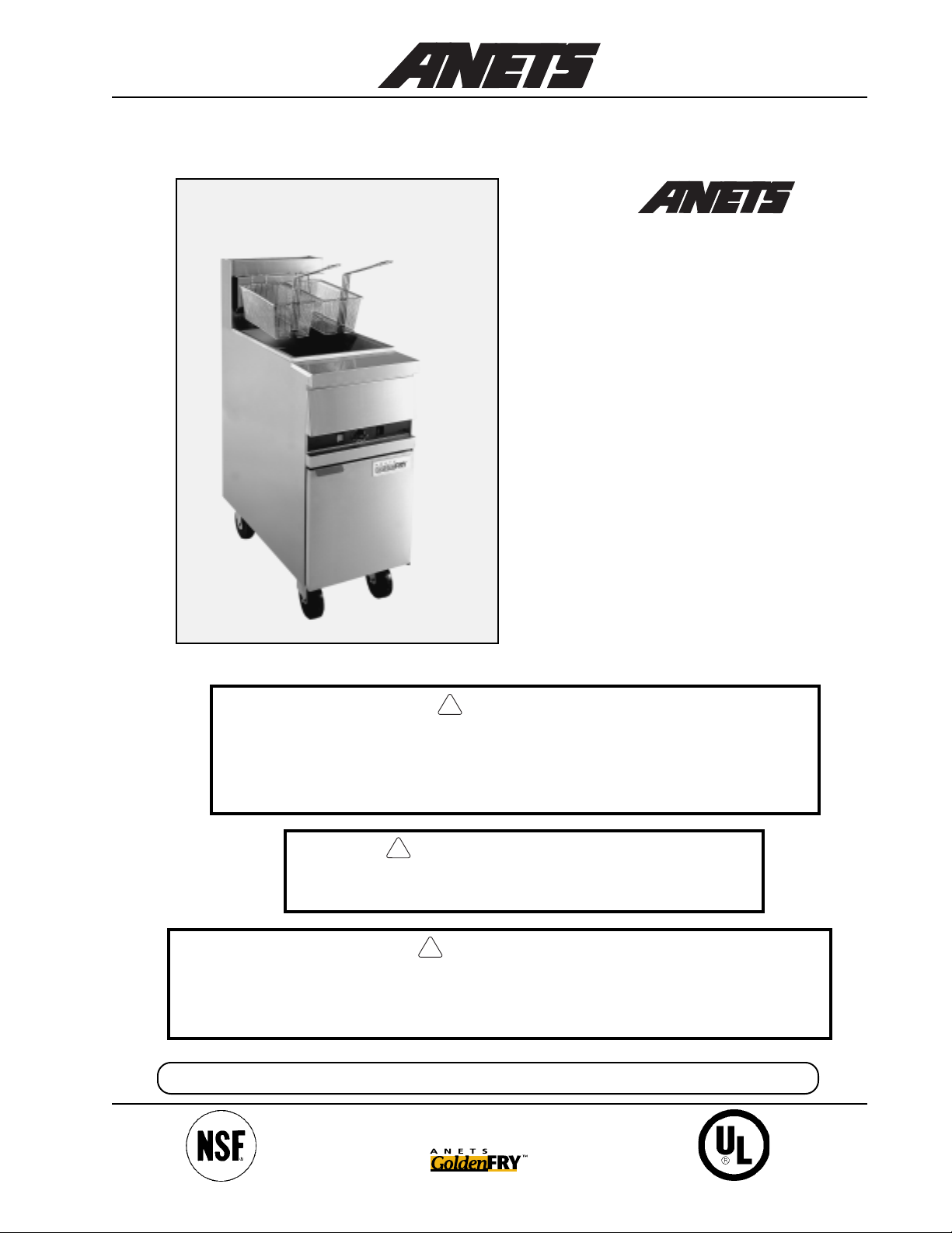
MX-14E shown with optional casters
FRFR
FR
FRFR
YERYER
YER
YERYER
Models
MX-14E, MX-14-2E,
MX-7E,
MX-14AA, MX-14-2AA,
MX-7A
Installation,
User Operation,
&
Maintenance
Manual
DANGER
!
Improper installation, adjustment, alteration, service, or maintenance can
cause property damage, injury or death. Read the installation, operating
and maintenance instructions thoroughly before installing or servicing this
equipment.
!
FOR YOUR SAFETY
DO NOT store or use gasoline or other flammable vapors
or liquids in the vicinity of this or any other appliance.
!
WARNING
After installation of this equipment, immediately contact your local gas
supplier to obtain information about what action to take whenever any
person smells gas. Post this information in a prominent location.
Keep this Manual in a Convenient Location for Reference
The Anets GoldenLine
Quality Equipment For The Restaurant, Supermarket, and Bakery Industries
Form I-105;
Rev. 10/01
Price $20.00 US
1

CONTENTS
Shipping Container Inspection ....................................................... 3
Fryer Gas Supply Specifications.................................................... 4
Fryer Electrical Specifications ....................................................... 5
Figure 1 - Fryer MX-14E Wiring Diagram ............................ 5
Code Requirements ...................................................................... 6
Figure 2 - Fryer Site Installation Requirements ....................... 6
Installation Requirements............................................................... 7
Installation Instructions .................................................................. 7
Leg Installation Instructions ..................................................... 7
Figure 3 - T ypical Leg Installation ......................................... 8
Leg Leveling Instructions......................................................... 8
Caster Installation Instructions ................................................. 8
Figure 4 - T ypical Caster Installation ..................................... 9
Caster Leveling Instructions .................................................... 9
Fryer Restraining Device Installation Instructions..................... 10
Gas & Electric Connection Instructions ....................................... 10
Fryer Operating Instructions........................................................ 11
Fryer Preparation For Use (“Boil Out” Instructions) .............. 12
Figure 5 - Draining the Kettle............................................... 12
Lighting Procedure................................................................ 13
Figure 6 - Gas Control V alve & Knob Positions................... 13
Shutdown Procedure ............................................................ 14
Food Product Frying Time Charts .................................... 15, 16
Daily Cleaning Procedure....................................................... 17
Monthly Maintenance Instructions .......................................... 18
Fryer Troubleshooting Guide .................................................19 - 26
Fryer W arranty ............................................................................ 27
2
!
DANGER
Read these specifications, Code Requirements, Installation Requirements, Installation Instructions, and Operating Instructions very carefully. Failure to follow the
Instructions could cause the fryer to malfunction. A fryer malfunction can result in
property damage, serious bodily injury, or death.
SHIPPING CONTSHIPPING CONT
SHIPPING CONT
SHIPPING CONTSHIPPING CONT
1. Carefully examine the shipping container for external damage. When damage is noted, notify the
delivery carrier immediately . Save all packing materials for damage claim examination.
2. If no external damage is noted, remove the shipping container from the fryer and examine the fryer
carefully for damage. Place the fryer in a safe location, if damage is noted, so that the freight damage
claims adjuster can examine the fryer .
3. Save the shipping container for use during leg/ caster installation. Refer to the Installation Instructions
for that procedure.
AINER INSPECTIONAINER INSPECTION
AINER INSPECTION
AINER INSPECTIONAINER INSPECTION
Models Covered By This Manual
MX-14E High Efficiency Stainless Steel Fryer
MX-14-2E High Efficiency Stainless Steel Split Pot Fryer
MX-14-7E High Efficiency Stainless Steel Half Size Fryer
MX-14AA High Efficiency Stainless Steel Fryer With Automatic Lifts
MX-14-2AA High Efficiency Stainless Steel Split Pot Fryer W ith Automatic Lifts
MX-7A High Efficiency Stainless Steel Half Size Fryer With Automatic Lifts
Standard Accessories furnished in the shipping carton with this fryer include:
Models MX-14AA, -14-2AA, MX-14E, and MX-14-2E Models MX-7A and MX-7E
2 Fryer Baskets 1 Screen 1 Fryer Basket 1 Screen
4 Adjustable Legs 1 Basket Hanger* 4 Adjustable Legs 1 Basket Hanger*
1 Drain Valve Extension 2 Basket Lift Frames ** 1 Drain Valve Extension 1 Basket Lift Frame **
1 Cleanout Rod 1 Cleanout Rod
*- Basket Hanger for MX-14E, MX-14-2E, or MX-7E only.
** - Basket Lift Frame for MX-14AA, MX-14-2AA, or MX-7A only.
NOTE:
computer with shortening melter, boil-out mode, and digital timers (Fri-tronic
(Filtronic™ II or Filter Mate™); a fryer cover; a drain table; a front drain tray; or four casters.
NOTE: A Parts List for each Anets Fryer is among the items shipped with each fryer. If an additional copy of this list is needed, please contact the factory as directed on the back cover.
Other available optional equipment may include a sediment tray; a microprocessor-based cooking
®
); a built-in filter system
3
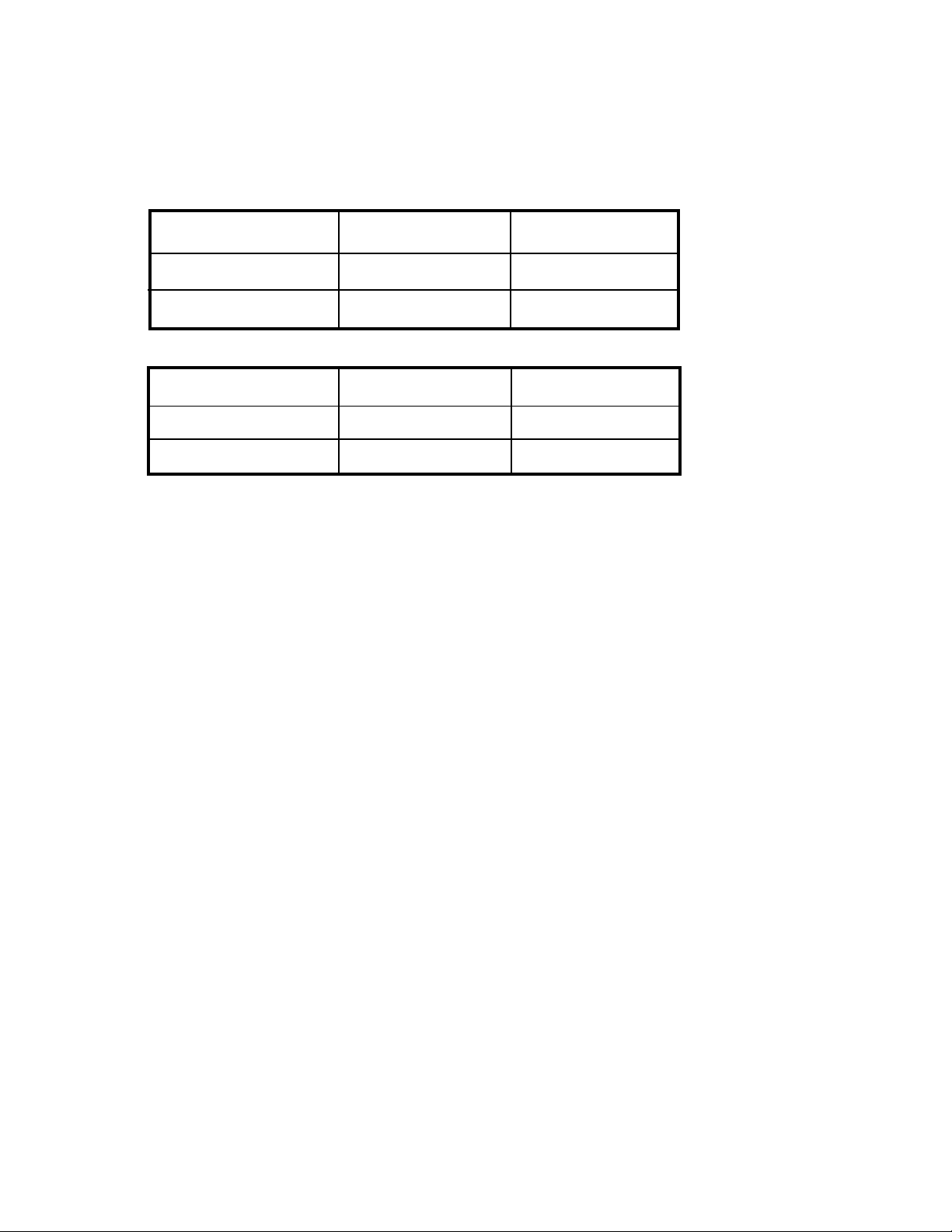
FRYER GAS SUPPLY SPECIFICATIONS
Please make sure that your desired fr yer location has gas
supply factors that are suitable for this product:
Models MX-14E, MX-14-2E, MX-14AA, &MX-14-2AA
INPUT REQUIRED:
11 1,000 BTU/Hr *
MANIFOLD PRESSURE
SUPPL Y PRESSURE***
Models MX-7E & MX-7A
INPUT REQUIRED:
55,000 BTU/Hr *
MANIFOLD PRESSURE
SUPPL Y PRESSURE***
Natural Gas Propane Gas
3½“ W.C.
6“ W.C., minimum 1 1“ W.C., minimum
Natural Gas
3½“ W.C.
6“ W.C., minimum 11“ W.C., mini-
**
**
10“ W .C.
Propane Gas
10“ W.C.
* - BTU/Hr Rating is based on sea level operation. For sites above 2000 feet, reduce this rating 4% for
each 1000 feet above sea level.
** - “ W .C. = Inches, W ater Column.
*** - Measure Supply Pressure when all other gas-powered equipment is operating.
Gas Supply Inlet Pipe must be ¾” NPT (National Pipe Thread) standard gas line. The gas supply inlet
line should be as straight as possible (fewest bends or elbows) to obtain the highest available gas pressure at
the appliance. Locate this inlet line horizontally at the center of the desired fryer location, approximately
8¼” above the floor .
NOTE: Using a flexible inlet line permits variation in the gas supply line location, both horizontally and
vertically .
Anets fryers are only for use with the type of gas specified on the spec plate. If a fryer requires modification
to use a gas other than that which is identified on the fryer spec plate, contact your Anets representative or
call (800) 837-2638.
4
FRYER ELECTRICAL SPECIFICATIONS
Please make sure that your desired fryer location has electrical
supply factors that are suitable for this product:
120 Volts, 60 Hz, (Refer to T able 1 for amperage requirements), 1-phase, three-wire connection, including
an electrical ground,
mounted inside the front door of each fryer.
via a dedicated circuit breaker. A model-specific electrical circuit diagram is
Table 1. Fryer Amperage
Model Amperage
MX-14E
MX-14-2E
MX-7E
MX-14AA
MX-14-2AA
MX-7A
Requirements
2 A.
4 A.
2 A.
7 A.
9 A.
5 A.
Install a dedicated, three-prong, outlet/ receptacle
within 5 feet of the desired fryer location to allow
the fryer’s power cable to be connected. Ensure
that the green (ground) wire of the fryer’s power
cable is attached to the fryer’s structure, providing
an electrical ground in accordance with applicable
local codes, or in the absence of local codes, with
the National Electrical Code, ANSI/NFP A 70
(latest edition) or the Canadian Electrical Code,
CSA C22.1 (latest edition) and CSA C22.2 (latest
edition).
WARNING
!
Electrical Grounding Instructions
(See inside of door for wiring diagram.)
This appliance is equipped with a threeprong (grounding) plug for your protection against shock hazard, and should
be plugged directly into a properly
grounded, three-prong receptacle. DO
NOT cut or remove the grounding prong
from this plug.
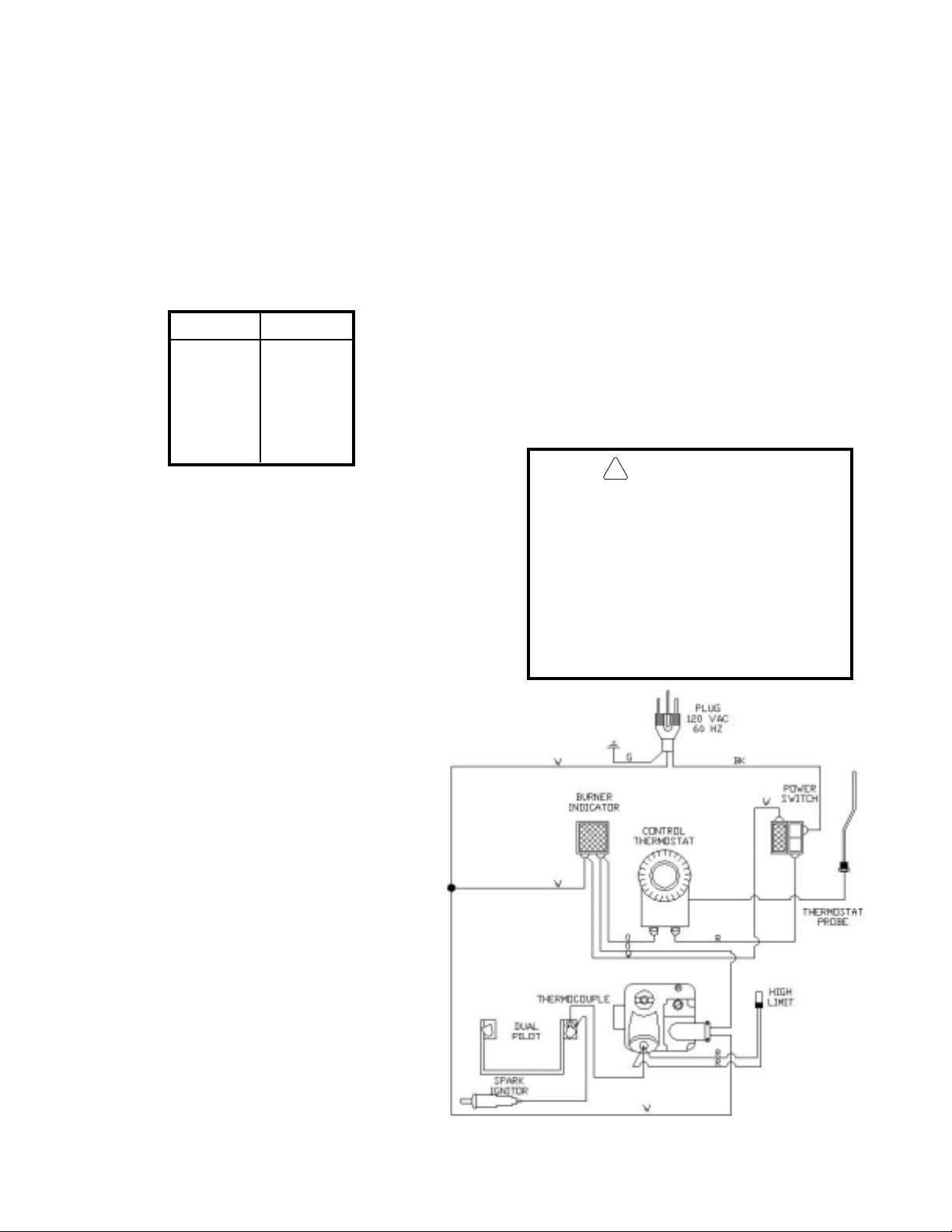
Figure 1 is the basic wiring diagram of an
MX-series fryer showing a typical circuit.
Some fryers may have other options that do
not appear in this basic wiring diagram. A
model-specific wiring diagram included with
each fryer shows all the actual parts and
their associated wiring connections. In
addition, fryers equipped with a built-in filter
system (Filtronic II or Filter Mate) and/or
built-in computer controls (Fri-tronic) have
a supplementary manual included for each
option.
Figure 1. Fryer Model MX-14E Wiring Diagram
5
CODE REQUIREMENTSCODE REQUIREMENTS
!
CODE REQUIREMENTS
CODE REQUIREMENTSCODE REQUIREMENTS
IMPORTANT: Read the Code Requirements
and the Installation Requirements and Iinstructions carefully, before starting the installation.
Contact the factory (800/ 837-2638) if any
problems or questions arise.
The fryer installation must conform with local
codes, or in the absence of local codes, with the
National Fuel Gas Code, ANSI Z223.1 (latest
edition); the Natural Gas Installation Code, CAN/
CGA-B149.1 (latest edition); or the Propane Gas
Installation Code, CAN/CGA-B149.2 (latest
edition), as applicable, including:
a. Disconnect the fryer and its individual shutoff
valve from the gas supply piping system during
any pressure testing of the gas supply system at
test pressures in excess of ½ psig (3.45 kPa).
b. Isolate the fryer from the gas supply piping
system during any pressure testing of the gas
supply system at test pressures equal to or less
than ½ psig (3.45 kPa).
c. For fryers utilizing floor casters, the fryer instal-
lation shall be made with a connector that
complies with the Standard for Connectors for
Movable Gas Appliances, ANSI Z21.69
(latest edition) or CAN/CGA 6.16 (latest
edition), and a quick-disconnect device that
complies with the Standard for Quick-Disconnect Devices for Use with Gas Fuel, ANSI
Z21.41 or CAN/CGA 1-6.9 (latest edition).
d. Restrict the movement of a caster-equipped
fryer by using a limiting device (for example, a
cable attached
both to the fryer and to a fix-
ture attached to the site structure) to avoid
depending on the connector and the quickdisconnect device or its associated piping to
limit fryer movement.
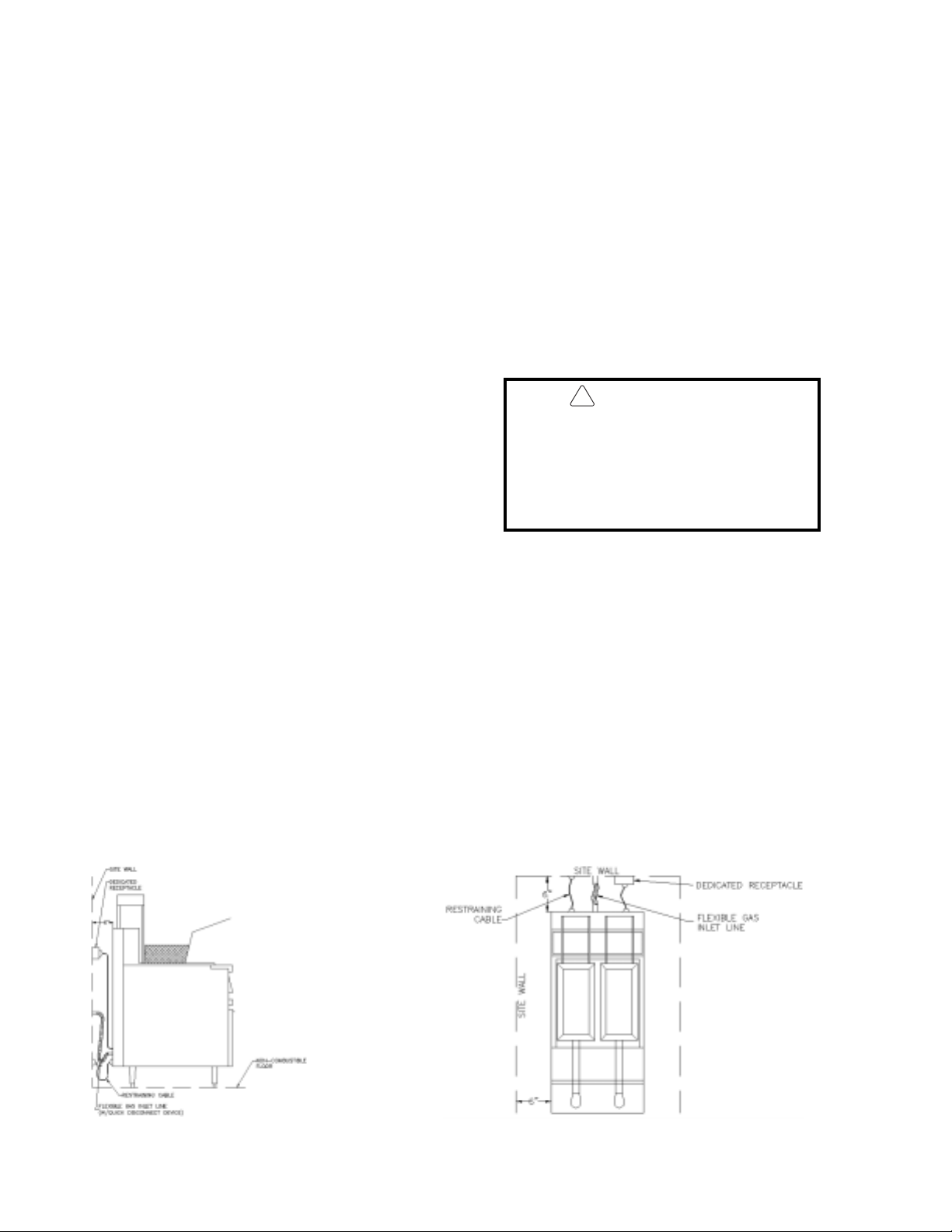
e. Install this fryer on a non-combustible floor
with its back and sides at least 6” away from
any combustible wall, as shown in Figure 2.
WARNING
Install this fryer under a ventilation
hood that conducts combustion pro ducts outside the building. Venting
must comply with ANSI/NFP A 96
(latest edition).
f . Install this fryer in a location where adequate
combustion and ventilation air is available.
Keep the area directly in front of the fryer open
for adequate air flow to the burners. DO
NOT obstruct the flow of combustion and
ventilation air.
g. Keep the fryer area free and clear from
combustibles and debris.
h. Attach a restraining device to each fryer, to
prevent the unit from tipping, which could
cause splashing of hot liquid .
From the top of the flue on
the fryer, allow a minimum
of at least 10 inches vertical clearance beneath a
ventilating hood.
Figure 2. Fryer Site Installation Requirements
6
INSTINST
INST
INSTINST
ALLAALLA
ALLA
ALLAALLA
TION REQTION REQ
TION REQ
TION REQTION REQ
UIREMENTSUIREMENTS
UIREMENTS
UIREMENTSUIREMENTS
Install the fryer in accordance with the preceding
Code Requirements, as well as the following
Installation Requirements.
1. DO NOT install this fryer in a mobile home,
trailer, or recreational vehicle.
2. Install this fryer in a location that has the fryer’s
electrical receptacle
away) to avoid straining the fryer’s power
cord. (See Figure 2.)
3. Install this fryer in a location that allows it to be
moved away from other adjacent appliances
for cleaning and maintenance.
NOTE: If the fryer is installed among
a row of appliances (“banked”), with
its only convenient movement forward,
sufficient room must be available in
front of the fryer to permit its separation from adjacent appliances for
cleaning and maintenance.
nearby (5 feet or less
4. Tightly fasten the legs (or casters) to the bottom of the fryer using the supplied hardware, to
prevent the fryer from tipping, wobbling or
rocking when it is in its desired location. Refer
to the following Leg Installation Instructions
or Caster Installation Instructions for leg
or caster attachment and leveling information.
CACA
UTION:UTION:
CA
UTION: Hood make-up air
CACA
!
5. Confirm that the air from the ventilation hood
flowing near the fryer
blowing on the rear of the unit, to prevent
affecting the burner flames and possibly causing
damage to plastic parts.
UTION:UTION:
MUST NOT flow in a manner that
restricts or impedes the natural flow
of combustion or ventilation air.
after installation is NOT
INSTINST
INST
INSTINST
ALLAALLA
ALLA
ALLAALLA
TION INSTRTION INSTR
TION INSTR
TION INSTRTION INSTR
LEG INSTALLATION
INSTRUCTIONS
1. Flatten the shipping carton (after unpacking the
fryer and its parts and accessories) for fryer
surface protection during leg installation.
2. Position the side of the fryer flat on the carton,
exposing the fryer bottom mounting brackets
for leg installation, as shown in Figure 3.
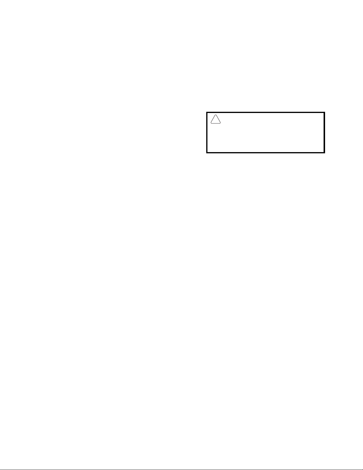
3. Place the leg mounting plate flush against the
mounting bracket on the fryer bottom, while
aligning the mounting holes.
4. Insert one mounting bolt through a flat washer
and then through the proper hole in the fryer
mounting bracket and through the leg mounting
plate.
UCTIONSUCTIONS
UCTIONS
UCTIONSUCTIONS
5. Screw a locking nut several turns onto the
mounting bolt.
6. Repeat steps 4 and 5 until all four mounting
bolts for a leg are in place with locking nuts.
7. Tighten the four locking nuts evenly and securely to hold the leg mounting plate against the
fryer bottom mounting bracket.
7
INSTINST
INST
INSTINST
Figure 3. Typical Leg Installation
ALLAALLA
ALLA
ALLAALLA
TION INSTRTION INSTR
TION INSTR
TION INSTRTION INSTR
UCTIONS UCTIONS
UCTIONS
UCTIONS UCTIONS
(Continued)
LEG LEVELING INSTRUCTIONS
1. Move the fryer to its desired location.
WARNING
!
The fryer MUST NOT tip, rock or wobble, to avoid splashing or spilling its HOT
shortening contents during operation.
CASTER INSTALLATION
INSTRUCTIONS
1. Flatten the shipping carton (after unpacking the
fryer and its parts and accessories) for surface
protection during caster installation.
2. Position the side of the fryer flat on the carton,
exposing the fryer bottom mounting brackets
for caster installation, as shown in Figure 4.
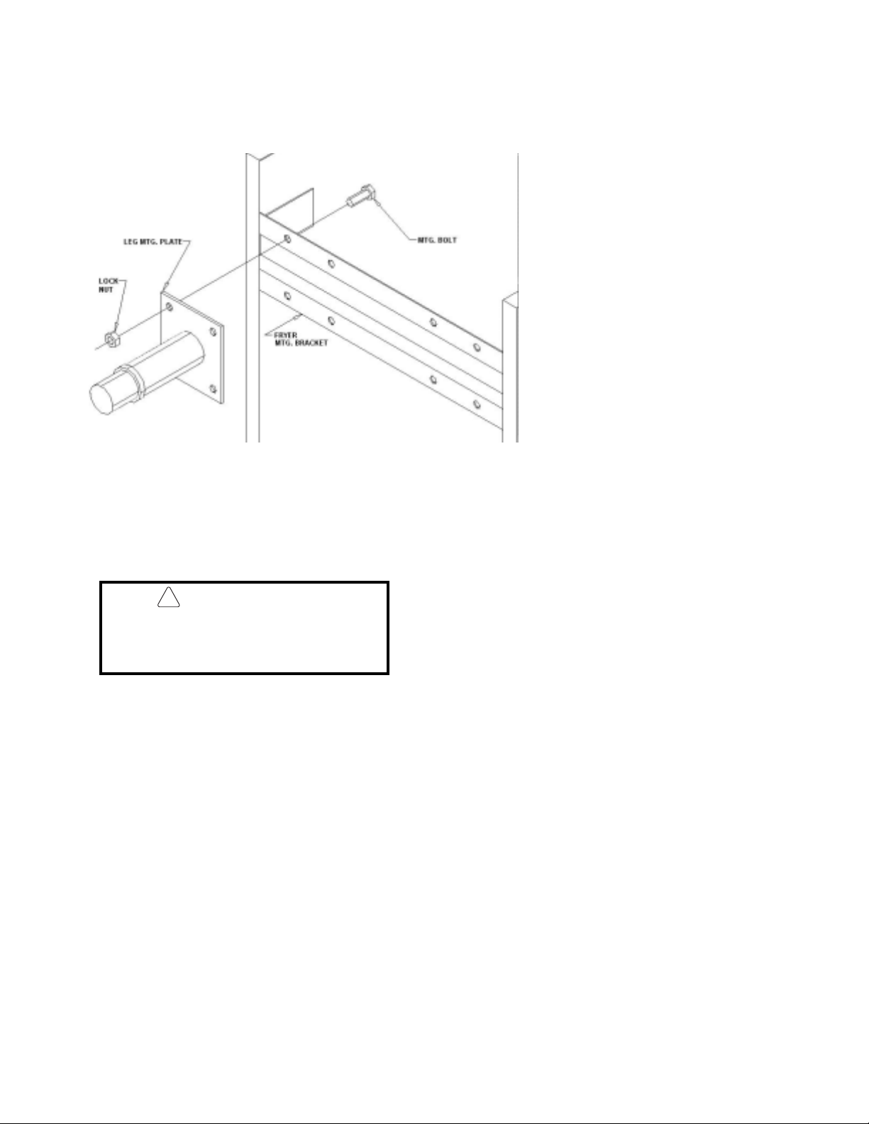
3. Mount locking casters on the front of the fryer
and fixed casters on the rear, by placing each
caster mounting plate flush against the mounting
bracket on the fryer bottom.
2. Turn the screw-type leg adjustment ends as
necessary to level the fryer, until NO tipping,
rocking, or wobbling is evident.
3. Perform the Fryer Restraining Device
Installation Instructions, referring to
Figure 2.
(supplied) and the mounting bracket, then
through the caster mounting plate.
5. Screw a locking nut several turns onto the
mounting bolt.
6. Repeat steps 4 and 5 until all four mounting
bolts for a caster are in place with locking nuts.
7. Tighten the four bolts evenly and securely to
hold the caster mounting plate against the fryer
mounting bracket.
4. Insert one mounting bolt through a flatwasher
8
INSTINST
INST
INSTINST
ALLAALLA
ALLA
ALLAALLA
TION INSTRTION INSTR
TION INSTR
TION INSTRTION INSTR
UCTIONSUCTIONS
UCTIONS (Continued)
UCTIONSUCTIONS
Figure 4. Typical Caster Installation
CASTER LEVELING INSTRUCTIONS
1. Move the fryer to its desired location.
2. Determine whether the fryer tends to wobble
or rock when in its desired location. If it
does, perform steps 3 through 9. If it does
not, skip to step 10, then proceed to the
Installation Instructions.
!
WARNING
The fryer MUST NOT tip, rock or wobble, to avoid splashing or spilling its HOT
shortening contents during operation.
3. Determine which caster requires adjustment
and the approximate amount of change
required to level the fryer .
4. Position the side of the fryer on the shipping carton, exposing the bottom of the fryer
with the caster mounting plates (Figure 4).
5. Completely unscrew the bolts holding the
caster mounting plate that requires the leveling
adjustment. Retain the locking nuts for later
reassembly .
CASTER LEVELING
INSTRUCTIONS (Continued)
6. Reinsert each bolt through its flatwasher and
the fryer mounting bracket; next, place a
spacer of the required size on the bolt before
inserting the bolt through its mounting hole on
the caster mounting plate and screwing a
locking nut onto the bolt.
7. Repeat step 6 for all remaining bolts.
8. Tighten all four locking nuts evenly and securely against the caster mounting plate and
the fryer bottom mounting bracket.
9. Return the fryer to its desired location. Lock
the front casters to prevent fryer movement
and check again for wobbling or rocking.
Repeat steps 3 through 9 until no wobbling or rocking occurs. When the fryer no
longer wobbles or rocks, perform step 10.
10. Perform the Fryer Restraining Device
Installation Instructions, referring to
Figure 2.
9
 Loading...