

Page 1
If you have any problems with the product, you can obtain the relevant services through the
following channels :
Facebook after - sales group: www.facebook.com/groups/anet3dprintersupport
Anet official website: www.anet3d.com
After – sales service email: anet@anet3d.com
User Manual
Page 2

Preface
1. Use Instruction
2. Installation Instruction
3. Spare Parts List
4. Parameter
5. Name of Parts
6. Installation
7. Machine Function Introduction
CONTENTS
7.1 Operation Interface
7.2 First Printing
7.2.2 Machine leveling
7.2.3 Load Filament
7.2.4 Remove Model
7.2.5 Unload Filament
Page 3

Preface
Dear customer:
Thanks for choosing and using Anet 3D printer. For your convenience, please read the instructions carefully before using and
follow the instructions strictly.
Special Version:
1. All the contents in this manual have been checked carefully. If there is any misprint or misunderstanding of them, Anet reserves the
right to interpret it.
2. This user manual is for reference only and does not constitute any form of commitment.
3. It is recommended to use Anet original filament.
Page 4

1. Use Instruction
In order to prevent damage to you and others in the process of using, Please be aware of the following:
● Please do not attempt to use the machine in any way undescribed in the instructions to avoid accidental personal injury and property
damage.
● Please do not place this machine near inflammable and explosive materials or high heat sources. Please place this machine in a
ventilated, cool and dust free environment.
● Please do not place the printer on a larger vibrating or other unstable platform. The shaking of the machine will affect the printing
quality.
● Please do not replace the power line of other products during installation. Please use the original power line supplied with the
machine. The working power supply uses 115V/230V AC. The power plug must be plugged into the three holes socket with ground wire
to avoid damage to components or accidents such as fire and electric shock.
● Please do not touch the nozzle and heating bed during the printer working to prevent high temperature burns and personal injury.
● Please do not wear gloves or wrappers when operating the machine in case the movable parts cause entanglement and cutting damage
on the human body parts.
● After printing, please use the remaining temperature of the nozzle to clean up the filament on the it with the help of tools.
Do not touch the nozzle directly with your hands during cleaning to prevent scalding.
● Please often do product maintenance. In the circumstance of power off, please regularly clean the printer body with dry cloth
to wipe away dust and bonded printing materials, foreign objects on guide rails, and lubricating oil is recommended for sliding
parts, screw rods and bearing parts.
● Children under 14 years old or people above 60 years old, please use this machine under the adult people to avoid personal injury.
● Some filaments will produce slight odor but it won't make people feel uncomfortable
Page 5

● Self-disassembly or modification may cause damage or abnormal performance, and your machine will no longer enjoy warranty service.
● It is recommended to use in a well-ventilated environment. Please cut off the power supply after using.
2 Installation Instruction
●Please make sure the packing is intact before receiving the goods.
●After unpacking, please check carefully whether the parts list is consistent with the physical parts.
●If you have any problems, please contact your supplier or Anet in time.
3 Spare Parts List
Page 6
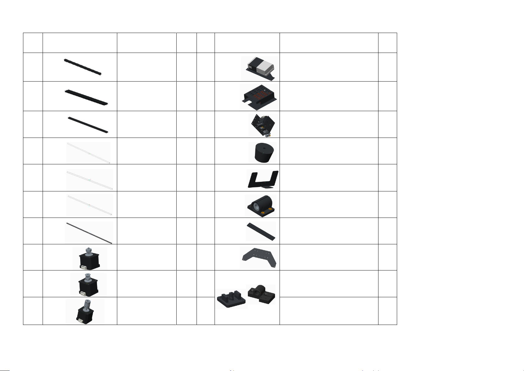
A8 Plus Parts List 1
No.
Picture
Name
Qty.
No.
Picture
Name
Qty.
1
X axis aluminum
profile 472mm
3
11
Power supply kit
1
2
Y axis aluminum
profile 422mm
2
12
Mainboard kit
1
3
Z axis aluminum
profile 500mm
2
13
Extruder kit(Black)
1
4
X axis guiding rod
496mm
2
14
Environmentally friendly rubber
pillar washer
4
5
Y axis guiding rod
442mm
2
15
Display screen
base
1
6
Z axis guiding rod
486mm
2
16
Linear bearing kit
7
7
Z axis screw rod
462mm
2
17
Heating bed shelf
1
8
X axis motor
1
18
Heating bed support
2
9
Y axis motor
1
19
Leading rod –limit switch
mounting block with pulley
1
10
Z axis motor
2
20
End cap
6
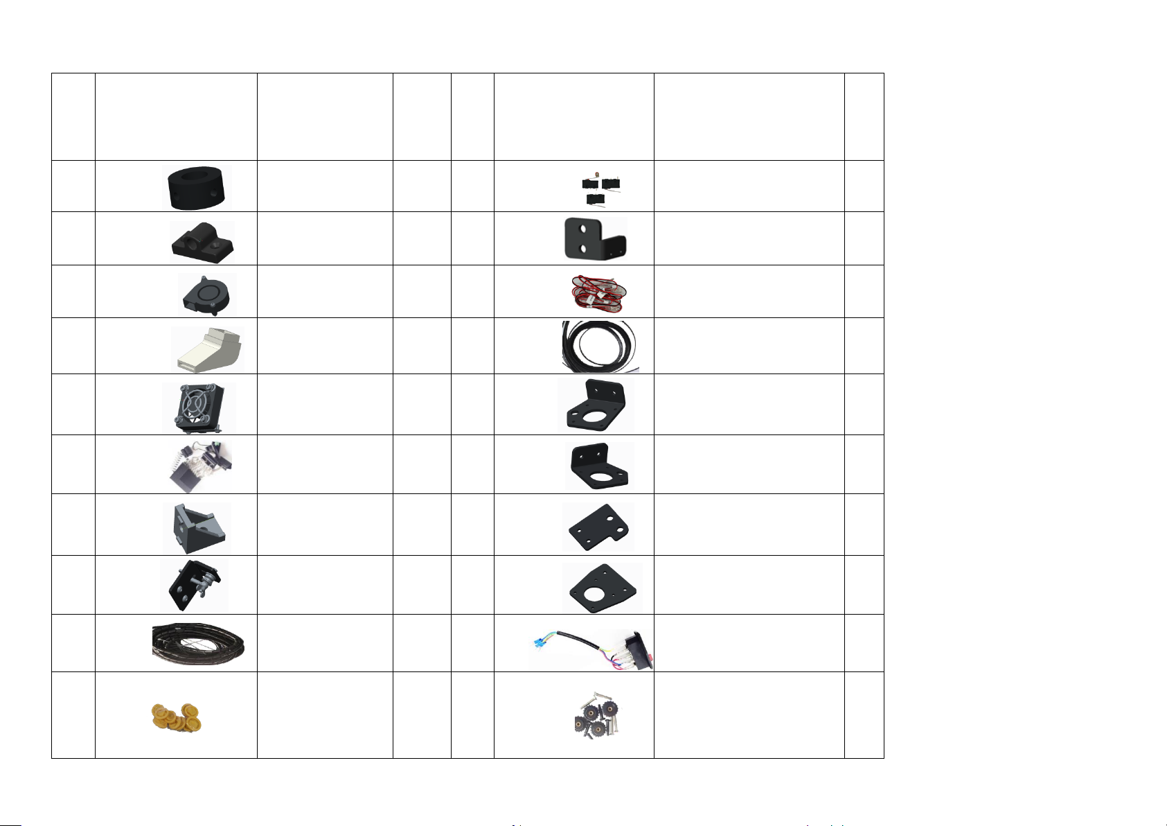
A8 Plus Parts List 2
Page 7
No.
Picture
Name
Qty.
No.
Picture
Name
Qty
.
21
Guiding rod shaft
sleeve
2
31 Limit switch
3
22
Leading rod fixed
block
3
32 Z axis limit switch holder
1
23 5015 air blower bag
1
33
Limit switch line
3
24 Wind mouth
1
34 GT2 belt bag 2m
1
25 Fan bag
1
35 Z1 axis motor fixed plate
1
26
Spare parts
1
36 Z2 axis motor fixed plate
1
27
Corner bracket
2
37 Z axis guiding rod fixed plate
2
28
Y axis belt bearing fixed
kit
1
38 Y axis motor fixed plate
1
29
Black winding pipe
bag
1
39
Power outlet
1
30
Rubber finger cot
10
40
M4*25 cross recessed
countersunk screw
M4*14 cylindrical head screw
M4 hand screw
10
Page 8
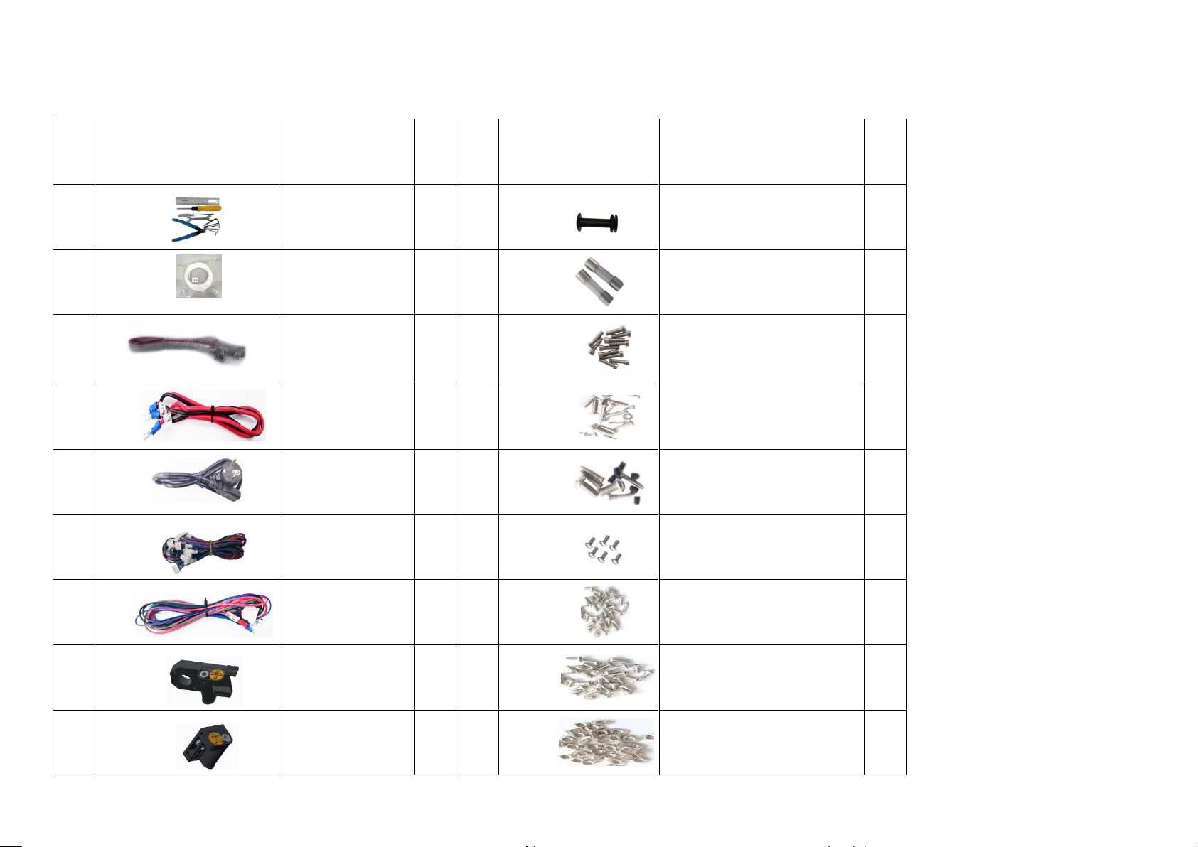
A8 Plus Parts List 3
No.
Picture
Name
Qty.
No.
Picture
Name
Qty.
41
Tool bag
1
52 Filament holder kit 2
1
42 PLA filament*10m
1
53 Protective tube bag(10A/15A)
2
43
FPC grey ribbon line
bag 1000mm
1
54
Screw bag 2
(M3*20/M3*25 、M5*20/M5*30)
25
44
Red and black belt
U-shaped cross line
(Double head)
1
55
Screw bag 3
(KM3*10/KM4*14/KM2*10/KM3*6)
19
45
Power line
1
56
Screw bag 4
(M4*10/ KB2.3*12/ M3*4)
14
46
A8 plus motor line
bag
1
57
Screw bag 5
(M3*6、M3)
20
47
Heating bed line
1
58
Screw bag 6
(M4*6)
26
48
Left Z axis screw
rod nut support
1
59
Screw bag 7
(M4*8)
34
49
Right Z axis screw
rod nut support
1
60
Screw bag 8
(M4 T nut)
33
Page 9
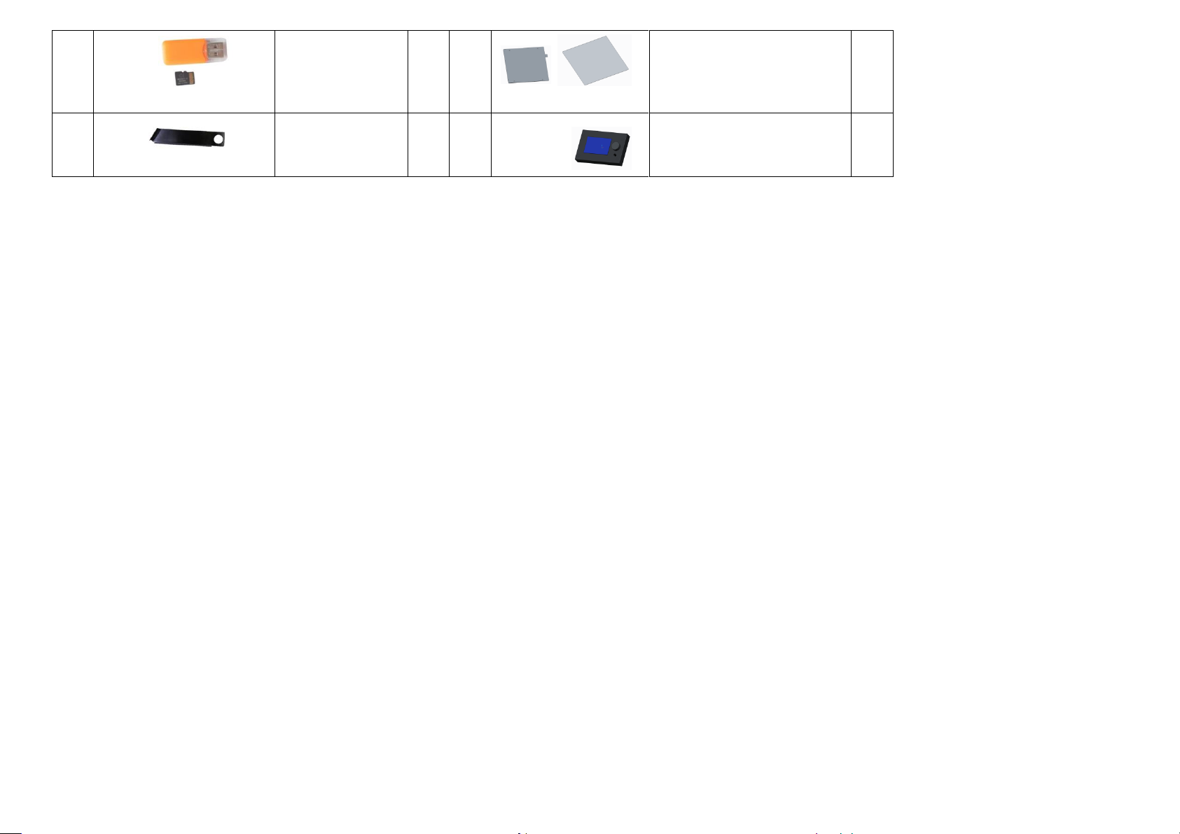
50
A8 Plus electronic data
(TF card, reader)
1
61
Heating bed 300*300*3mm
Tempered glass
2
51
Filament holder kit 1
1
62 Display screen
1
Page 10

Model:A8 PLUS
Nozzle diameter: 0.4mm
Layer precision:0.1-0.4mm
Product dimension:612*462*573mm
Printing speed: 40-120mm/s
Product weight:10±0.1kg
XY axis position precision:0.015mm
Packing dimension:580*375*175mm
Z axis position precision:0.004mm
Packing weight:12.1±0.1kg
Printing material: PLA, ABS, HIPS etc.
Build volume:300*300*350mm
Filament tendentiousness:PLA
LCD:12864 LCD
Filament diameter:1.75mm
Offline printing: Yes
Software language: English
Support file format:G-Code、Gco
Moulding support automatically: Yes
Operating systems:Windows, MAC
Slice software:Cura
Environmental requirements:
Temperature 0-40℃ Humidity 5-80%
4 Product Parameter
Page 11
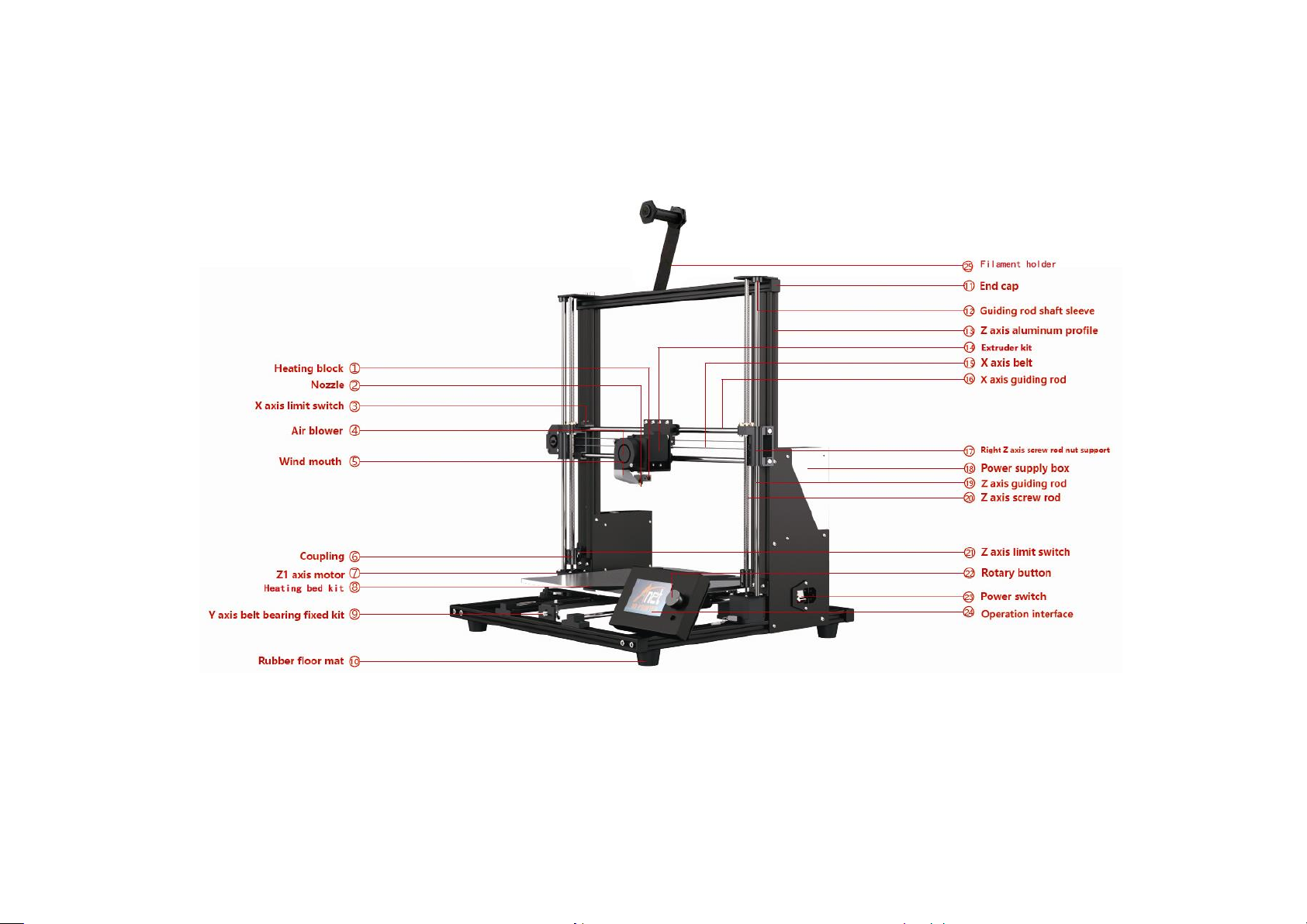
5. Name of Parts
Page 12
No.
Name
Qty.
1
X axis aluminum profile 472mm
2
2
Y axis aluminum profile 422mm
2
3
End cap
4
4
Environmentally friendly rubber pillar washer
4
5
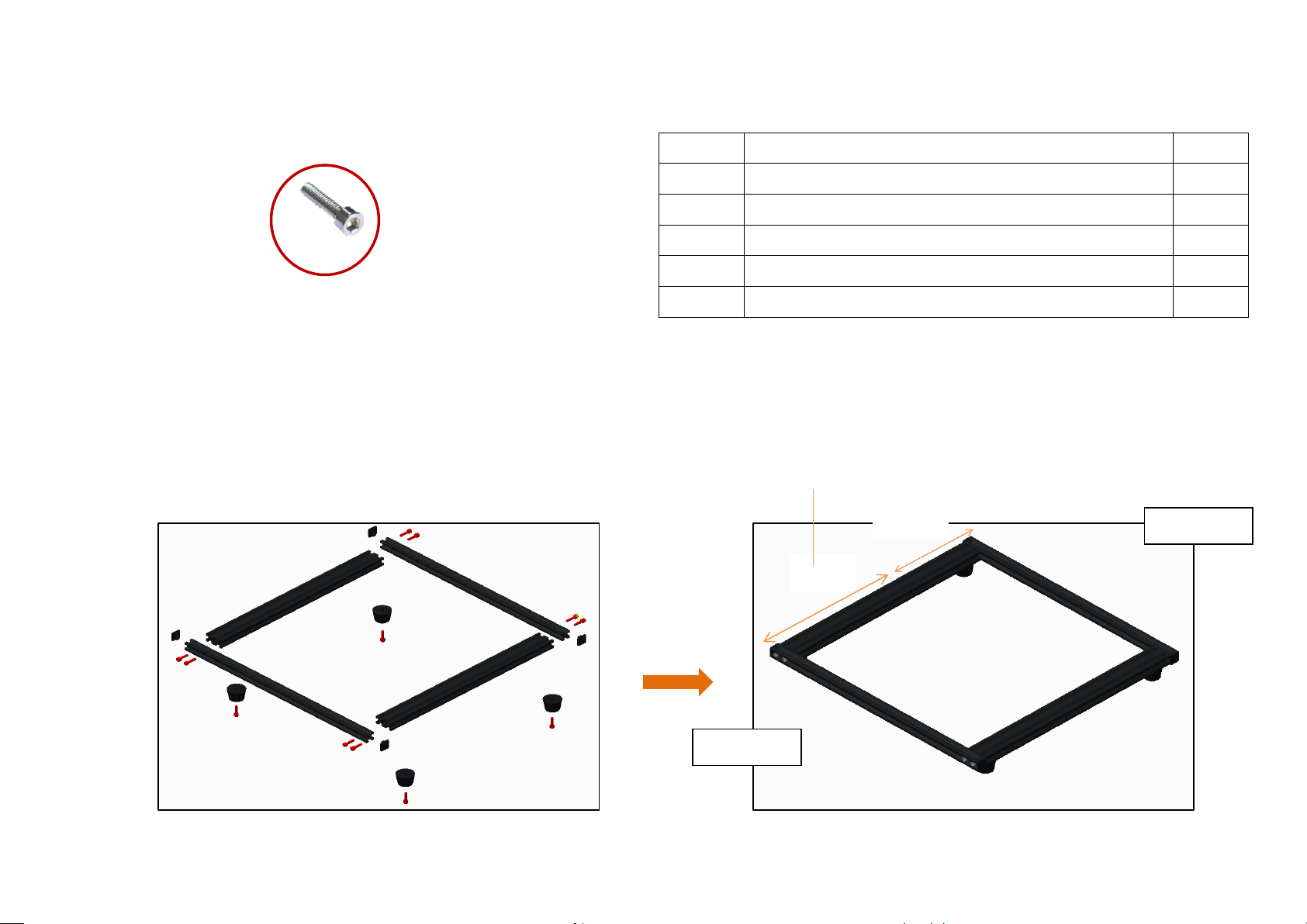
M5*20 socket hexagon screw
12
M5*20
Before assembly
After assembly
Front X axis
Rear X axis
The Y axis is separated from the hole position, the
front section is long, and the rear section is short.
Long
Short
Step 1
Page 13

No.
Name
Qty.
1
Y axis guiding rod 442mm
2
2
Linear bearing kit
4
3
Leading rod fixed block
3
4
Leading rod –limit switch mounting block with pulley
1
5
Limit switch without pulley
1
6
2
Before assembly
After assembly
Step 2
Page 14
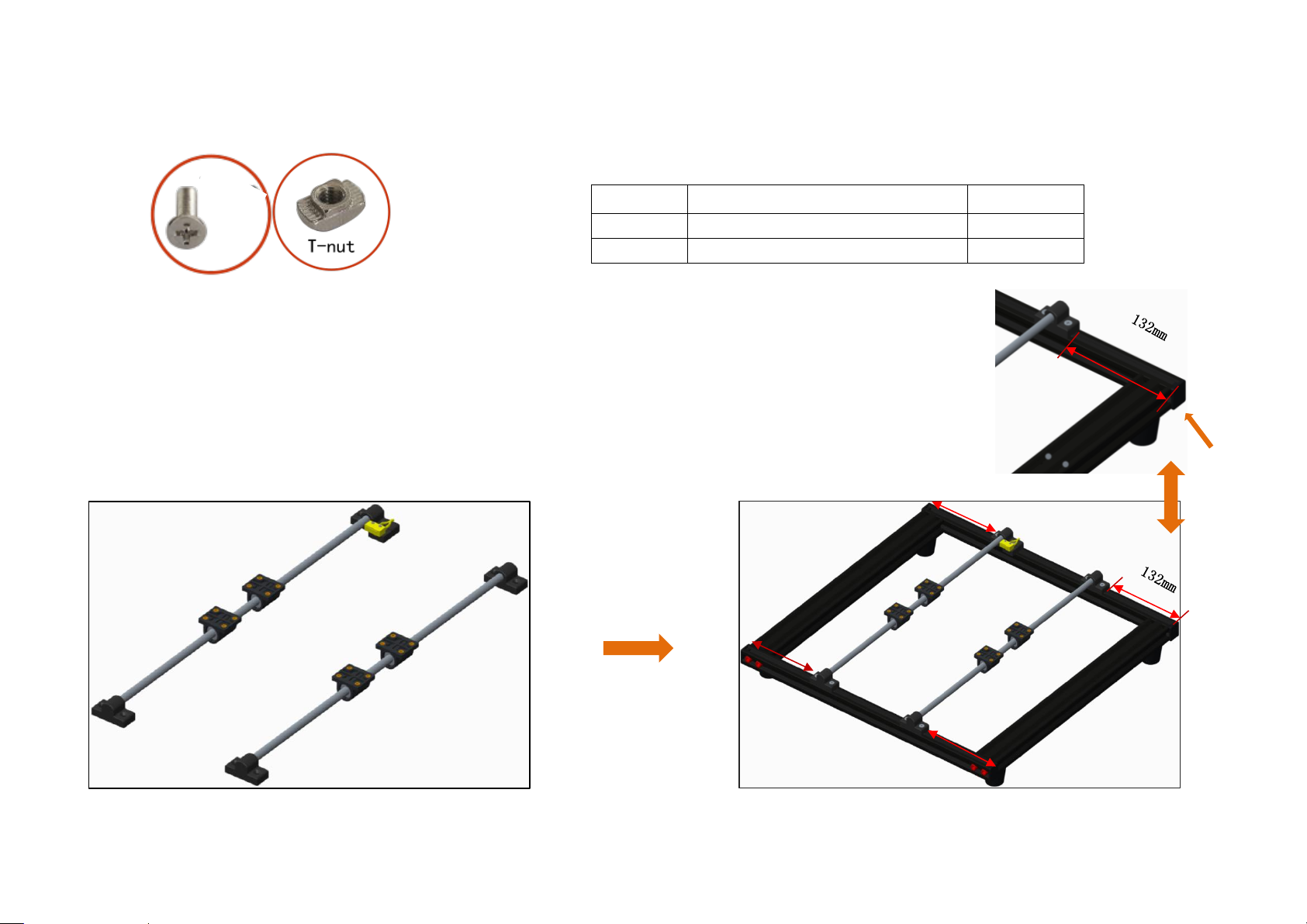
No.
Name
Qty.
1
M4*14
8
2
T – nut
8
Attention: The size of the double arrow in the drawing is
132 mm ( the distance from the center of the leading rod fixed
block to the edge of the profile ), which is controlled
during assembly.
M4*14
Before assembly
After assembly
End cap
Step 3
Page 15
No.
Name
Qty. 1 Y axis motor fixed plate
1
2
Y axis motor kit
1 3 socket hexagon screw M3*6
4
4
socket hexagon screw M4*8
2
5
M4 T – nut M4
2
M3*6
M4*8
Note: 1. Please fix it in the center of rear X axis aluminum
profile
2. M4 * 8 screws pass through the Y axis motor fixed plate,
screw on the T - nut ( entering 2 - 3 thread teeth ), put
it into the X - axis profile slot, tighten the screw ( the
nut will rotate 90 degrees during this process ), and corner
bracket will be fixed.
Note: Fix the Y axis motor fixed plate to the Y axis motor
kit with 4 M3*6 screw
Before assembly
After assembly
Step 4
Page 16

No.
Name
Qty. 1 Y axis belt bearing fixed kit
1
2
M4*8 Socket hexagon screw
2
3
T-nut M4
2
1.ease fix it in the center of front X axis aluminum profile.
( entering 2 - 3 thread teeth ), put it into the X - axis profile slot, tighten
the screw ( the nut will rotate 90 degrees during this process ), and corner bracket
will be fixed.
Before assembly
After assembly
Step 5
Page 17

No.
Name
Qty.
1
Hotbed support
2
2
Hotbed shelf
1
3
M4*8 Socket hexagon screw
22
4
Cylindrical head screw M4*14 Black
2
Fix M4*14 screw in the left hole
Before assembly
After assembly
Step 6
Page 18

No.
Name
Qty. 1 Belt
1 2 Belting
2
Note: The belt is cut to a proper length and fixed on the two M4 * 14 crews in step 6,
Please tighten the belt and press it to see if it is loose.
Before assembly
After assembly
Step 7
Page 19

No.
Name
Qty.
1
M4*25
4
2
Spring
4
3
Plastic hand screw
4
4
Heating bed300*300*3mm
1
5
Toughened glass
1
6
Clips
4
M4*25
Attention: Fix the hot bed on the heating bed support in sequence as shown in the picture.
M4*25
Heating bed
Spring
Hotbed support
Plastic hand screw
Before assembly
After assembly
Step 8
Page 20

No.
Name
Qty. 1 Right Z axis screw rod nut support
1
2
X axis motor kit
1
3
Limit switch with pulley
1 4 Socket hexagon cylindrical head screw M3*20
4
5
Cross recessed countersunk screw
KB2.3*12
2
The motor connection port is facing
down, as shown in the figure
Before assembly
After assembly
Step 9
Page 21

No.
Name
Qty.
1
Linear bearing
3
2
496mm X axis guiding rod
2 3 Right Z axis screw rod nut support
1
Before assembly
After assembly
Step 10
Attention: Please install in the direction shown in the picture.
Page 22

No.
Name
Qty. 1 Extruder kit
1
Loosen the nut and exit
the extruder
1. Loosen the nut and separate the extruder from the L-shaped black aluminum .
2..Remove the 2 M3*6 screw and use them later.
Before disassembly
After disassembly
L-shaped black aluminum
Extruder
M3*6
Step 11
Page 23

Step 12
No.
Name
Qty.
1
L-shaped aluminum holder
1
2
Socket hexagon screw M4*6
12
Fix the L-shaped aluminum holder in the linear bearing
Before assembly
After assembly
Page 24

Step 13
No.
Name
Qty.
1
Extruder
1
安装后
Put the extruder into the L-shaped
aluminum holder and tighten the nut
Before assembly
After assembly
Page 25

Step 14
No.
Name
Qty.
1
Fan fixed plate
1
2
Fan
1
3
Air blower
1
4
Wind mouth
1
5
M3*15 Socket hexagon screw M3*15
4
6
Ø3 Gasket
4 7 Socket hexagon screw M3*6
2 8 Socket hexagon screw M3*18
2
M3*6
M3*15+ φ3
M3*18
Fix the fan fixed plate in the L-shaped aluminum holder with 2 M3*6 screw
Before assembly
After assembly
Page 26

Step 15
No.
Name
Qty.
1
Belt
1 2 Belt adjusting fixing block
1 3 Belt adjusting sliding block
1 4 M3*25 Socket hexagon screw
1
5
M3 nut
1
6
M3*10 Countersunk screw
2
Flanged Bearing
Gear
Connect the gear and flanged bearing with a belt ,and sleeve the
belt adjusting fixing block and sliding block, after fixing ,press
the belt to see if it is loose.
M3 nut
M3*25
The fixing block is fixed with M3*10 countersunk
screw
Before assembly
After assembly
Page 27

Step 16
No.
Name
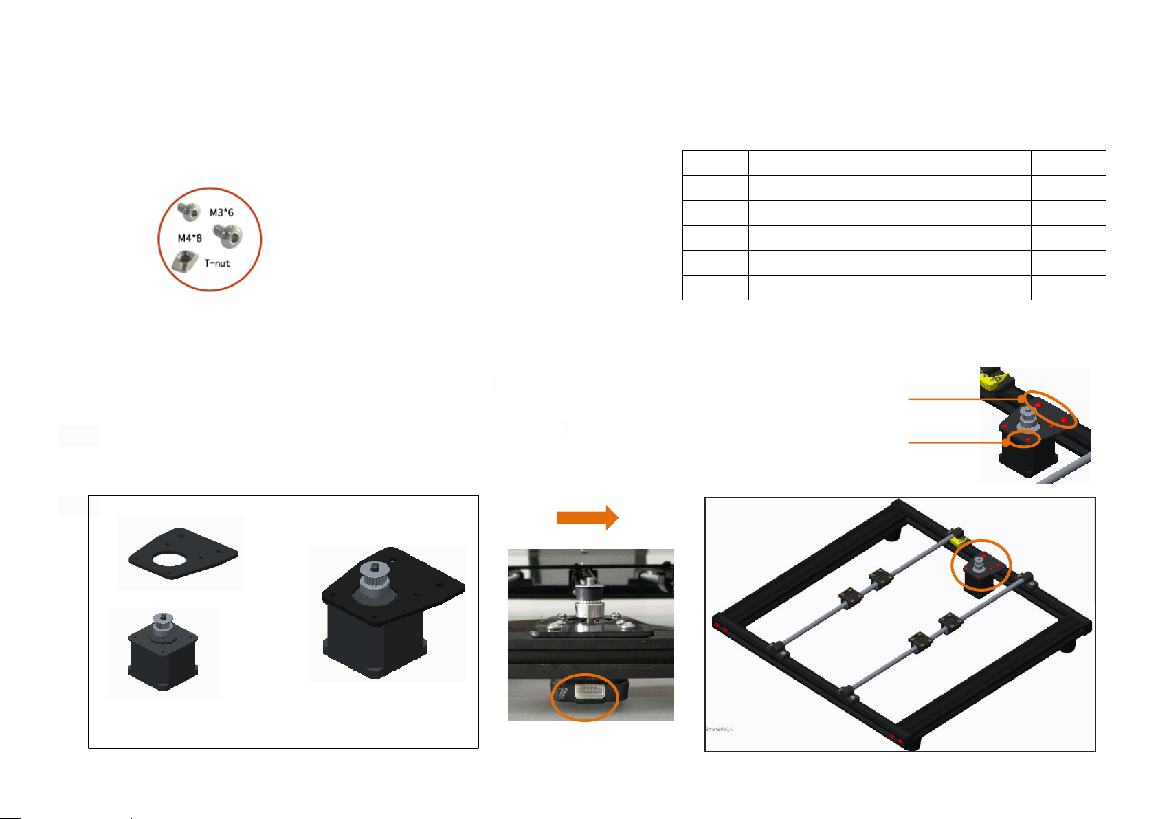
Qty. 1 Z1 axis motor fixed plate
1 2 Z2 axis motor fixed plate
1
3
Z axis motor kit
2
4
Socket hexagon flat round head screw M3*6
8
5
Socket hexagon flat round head screw M4*8
4
6
M4 T-nut
4
M3*6
Please install as shown in the figure, pay attention to the
direction relationship between the circular hole and the motor.
Before assembly
After assembly
Page 28

Step 17
No.
Name
Qty.
1
Z axis aluminum profile 500mm
2
The T-nut is inside the profile clamping groove
Z1 in the left ,Z2 in the right.
Z1
Z2
Before assembly
After assembly
Page 29

Step 18
No.
Name
Qty.
1
486mm
Z axis guiding rod 486mm
2
2
462mm
Z axis screw rod 462mm
2
.
Note: Rotate the screw rod clockwise down to the bottom, and
then lock the self-contained top tightening screw
462mm*2
486mm*2
Lock the self-contained top tightening screw
Before assembly
After assembly
Page 30

Step 19
No.
Name
Qty.
1
Guiding rod shaft sleeve
2
2
M3*4 Black jackscrew M3*4
4
3
Z axis guiding rod fixed plate
2
4
M5*30 Socket hexagon cylindrical head
screw
4
5
End cap
2 6 X axis aluminum profile 472mm
1
M5*30
Guidi
ng rod
shaft
sleev
e
Z axis
guiding
rod
fixed
plate
End
cap
Note: Fix the guiding rod shaft sleeve with M3*4 black jackscrew
M3*4
Before assembly
After assembly
Page 31

Step 20
No.
Name
Qty. 1 M4*8 socket hexagon screw
4
2
M4 T-nut
4
3
M5*20
Socket hexagon cylindrical head screw
4
Vertical Frame
Chassis
Attention: Put the vertical frame on the chassis, align it with the
holes on the aluminum profile of the chassis
, and fix to on the chassis with 4 M5 * 20 screws.
Corner bracket installation: Make the screws
through the corner bracket, screw on the T - nut
( 2 - 3 thread tooth ), put it into the profile
slot ( inside ), tighten the screws with a wrench,
and the T - nut will rotate 90 degrees and the
corner bracket will be fixed.
Corner bracket installation diagram
Before assembly
After assembly
Page 32

Step 21
No.
Name
Qty. 1 Power supply kit
1 2 Mainboard kit
1
Remove the M3 * 6 socket hexagon screw
for fixing the power supply, split the
power supply and power supply fixing
frame, and retain the 3 inner hexangular
set screws.
Split the motherboard kit, retain the 4 m3 * 6 socket hexagon screws, and then install the M4 *
8 socket hexagon screws and T- nuts in the 3 holes on the mainboard.
The circle is an enlarged view
( side ) of the T - nut
installation
Before assembly
After assembly
Page 33

Step 22
No.
Name
Qty. 1 Power outlet
1
2
Red and black with U-shaped line
(Double head)
1
3
M4*6 socket hexagon screw
4
3
T-nut M4
4 4 M3*6 socket hexagon screw
5
Note: The wiring diagram of the switch power supply, 1.2.3, are respectively the
input wire L ( brown ), the zero line N ( blue ) and the ground wire ( yellow green ),
which are connected to the AC socket wire. 4.5.6 are the output negative COM ( black
- ), 7.8.9 are the output positive V + ( red + ), please make sure the wiring correct
to prevent danger!
1
2
3
4 5 6
7
8
9
M3*6
The circle is an
enlarged view
( side ) of the T -
nut installation
Before assembly
After assembly
Page 34

Step 23
No.
Name
Qty.
1
KM2*10
2
2
M4*8 cross recessed countersunk screw
2
3
T-nut M4
2 4 Limit switch (without pulley)/Limit switch support
1
5
A8 plus motor line bag
1
6
Heating tube6*20mm( with line 1.5m)
1
7
Hotbed line
1
8
FPC grey ribbon line bag
2
Limit switch support
M4*6
Limit switch
Z1 axis
Z2 axis
Installation diagram of
limit switch support
70mm
The installation position of the Z - axis limit
switch is 80 mm away from the Y - axis profile
Page 35

Step 24
No.
Name
Qty.
1
Motor line bag
5 2 FPC grey ribbon line bag
1
3
Limit switch line bag
3
Fix mainboard on the groove
Please pass the lines(with -A word) of extruder, X
axis limit switch and X axis motor through the
square hole on the mainboard.
Pass all other wires through the holes
under the mainboard (The cable with the
word "-A" is connected to one end of the
mainboard.)
The cable with the word "-A" is connected to one end of the
mainboard.
Page 36

Step 25
Name
Cable label
Mainboard
port
Name
Cable label
Mainboard port
X axis motor
X-Motor-A
X
X axis limit switch
X axis limit switch line-A
S-X
Y axis motor
Y-Motor-A
Y
Y axis limit switch
Y axis limit switch line-A
S-Y
Z1 axis motor
Z1-Motor-A
Z1
Z axis limit switch
Z axis limit switch line-A
S-Z
Z2 axis motor
Z2-Motor-A
Z2
Heating bed
Heating bed-A
BED
E axis motor
E-Motor-A
E
Thermistor-A
B-T
Extruder
Extruder thermistor-A
E-T
TF card
TF card port
Extruder
Extruder heating tube-A
END
power supply
Power supply line-A
+ -
Display screen
LCD grey ribbon cable
-A
LCD
Fan
Fan with line-A
FAN2
Display screen
J3 grey ribbon cable-A
J3
Air blower
Air blower with line-A
FAN1
According to the schematic diagram of the line port and the label of the wiring, find the corresponding wiring and
plug in all the wiring, the cable with the word "-A" is connected to one end of the mainboard.
Wiring sheet:
1. Except that the electronic wire shown in step 6 passes through the jack at the upper end of the mainboard, the remaining
electronic wires are all pulled out from the holes under the mainboard, and the machine is connected from below the machine
to avoid affecting the operation of the machine.
Page 37

2. When all wiring is plugged in, please remove the zip ties on the black belt, plug in the power line, turn on the machine for
There is no need to separate
positive and negative electrodes
(+ red line , - black line )
Heating bed thermistor
Heating bed
TF card port
trial operation(please refer 7.2 First Printing ), and then install the mainboard shell after everything is normal.
Page 38

Step 26
No.
Name
Qty.
1
Display screen
base
1
2
Display screen
1
3
T-nut M4
4
4
M4*6
4
5
Magnet
3
magnet
Display bas
M4*6
LCD
J3
Note: 1. The LCD / J3 wiring of the display screen corresponds to the socket screen printing ( LCD / J3 ) on the control panel.
Please do not connect the wrong wiring.
2. Put the display screen directly on the magnet after installation to complete the installation of the display screen and
components.
Before assembly
After assembly
Page 39

Step 27
No.
Name
Qty. 1 Filament holder
1
2
M4*8
2
3
T-nut
2
Before assembly
After assembly
Page 40

Step 28
Front
Back
Final Schematic diagram
Page 41

7 Machine Function Introduction
Printing
Printing time
Status bar
Rotary button
(left and right for selection,
press for confirmation)
Reset button
Speed adjustment ratio
Target temperature
Actual temperature
Actual temperature of heating bed
Target temperature
XYZ axis coordinates
7.1 Operation Interface
Page 42

7.2 First Printing
TF card
TF card installation completed
7.2.1 Install TF Card
Insert TF as shown in picture 2
7.2.2 Machine leveling
1. Auto home operation: Adjust the spring around the heating bed to the tightest ( counterclockwise ), press the rotary button
to enter the main menu, select“Prepare”→“Auto home”, the machine begins to move toward the position of the limit switch until
it stops moving after touching the limit switch.
2.Disable steppers operation: Press the rotary button to enter the main menu, select“Prepare”→“Disable steppers”.
3.Manual leveling:Move the nozzle to the heating bed, and observe the distance between the nozzle and the heating bed from the
front of the machine. If the distance between the nozzle and the four corners of the heating bed is 0.1mm (the thickness of a piece
of A4 paper, A4 paper can pass through the gap and feel slight resistance), leveling is not required. If the distance between the
Page 43

nozzle and the four corners of the heating bed is greater than or less than 0.1mm, adjust according to step 4.
The distance between the nozzle
and heating bed
Attention: turning the nut counterclockwise is tight
and turning the nut clockwise is loose.
spring
Nut
A4 paper can pass through the distance between the
four corners of the heating bed and nozzle, and feel
slight resistance.
4. Adjust the distance: Fine - tuning the "distance" to make its size about 0.1mm meet the printing requirement. Move the nozzle
to the other three corners of the heating bed, and sequentially adjusting the spring compression of the four corners of the heating
bed in one direction (clockwise or counterclockwise), so that an A4 paper (about 0.1mm) can pass through this distance and feel a
slight resistance, and there is no scratch on the platform when moving the extruder.
Page 44

The heating bed and extruder reach
7.2.3 Load Filament
1. Perheat Machine
Before loading filament, the machine needs to be preheated. The following pictures illustrates PLA filament as an example, and
the operation is as follows.
Operating method: Press the knob→“ Prepare”→“ Preheat PLA”→“Preheat PLA”, the machine starts to perheat ( the main interface
shows that the machine is perheat ).
。
Note: If you want to print with ABS filament, you must select " Preheat ABS" for preheating.
Page 45

2 Load Filament
Load filament automatically:
1. A roll of PLA filament: Filament specifications: Diameter :1.75mm; Material: PLA ;Printing temperature: 200-230℃;
2.Please press rotary button →“ Prepare”→“ Change filament”, the main interface will display “Heating nozzle Please wait……”,the
interface will display “Wait for start of the filament change” after the nozzle temperature rises to the target temperature →
“Wait for filament unload ” →“Insert filament and press button to continue…” → then please press rotary button;
3. Straighten up the filament (or cut the filament into bevels with plier),then pass the filament through the extruder;
4.Meanwhile the main interface will display “Wait for filament load” →“Wait for filament extrude”,please click “Resume print”
to start printing;
5. If the nozzle has filament outflow, the installation of filament is successful. If the installation of filament is not successful,
please select“Extrude more”to re-load.
Attention: The function of automatic material advance and retreat is carried out according to the steps of material return first and material feed later, when the
first printing has not started installing filament yet, please wait for 1 - 3 minutes. After the interface displays “Insert filament and press button to continue”,
insert filament into the extruder for automatic feeding.
Page 46

Heating nozzle
Please wait…
Wait for start of the filament change
Wait for filament unload
Insert filament and press button to continue…
Wait for filament load
Wait for filament extrude
Resume print
Extrude more
Page 47

3 Printing
1. After leveling is completed and the filament is installed successfully, press the rotary button to enter the main menu, press
" Print from SD" → " Main" and select the file under " Main" to start first printing.
2. In the process of printing, if you want to pause printing, press the rotary button to enter the main menu, press " Prepare"
→ " Pause print" to pause printing, and press " Resume print" to resume printing.
3. If you want to stop printing during printing, press the rotary button to enter the main menu, press " Prepare" → " Stop print"
to stop printing, press the reset button to resume normal operation of the machine and select to reprint the model.
Page 48

7.2.4 Remove Model
Wait for start of the filament change
Wait for filament unload
Heating Nozzle
Please wait…
Please remove the model by hand after printing .
7.2.5 Unload Filament
Automatic unload filament (taking PLA as an example)
Please press rotary button →“ Prepare”→“ Change filament”, the main interface will display “Heating nozzle Please wait……”,wait
for 1-2 mins ,the interface will display“Wait for start of the filament change”after the nozzle temperature rises to the target
temperature →“Wait for filament unload ” ,the machine automatically unload filament ,then pulls out the filament in the vertical
direction and unload the filament.
Page 49

 Loading...