

A
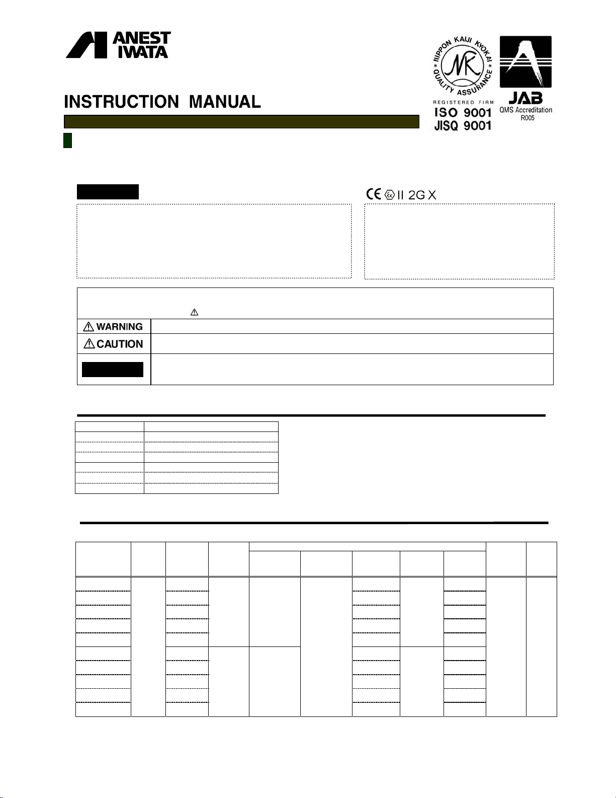
HVLP Compliant Spray gun
LPH-80
Low V olume Low Pressure
Important
This manual contai ns I MP OR TA NT WA RNI NG S and INSTRUCTIONS.
Equipment in this manual is exc lus iv ely f or pai nting purpos es.
Do not use for other purposes .
The operator shall be fully conversant with the requirements stated in this
instruction manual including important warnings, cautions and operation and
correct handling.
Read and understand the instruction manual, before use and retain for
reference.
Be sure to observe wa rnings and c auti ons in t his ins truc tion manual.
If not, it can c aus e pain t ejec ti on an d ser ious bodil y inj ury by d rawing organ ic s olv ent .
Be sure to observe following marked items which are especially important.
Indicates a potentially hazardous situation which, if not avoided, may result in serious injury or loss of life.
Indicates a potentially hazardous situation which, if not avoided, may result in minor or moderate injury or property
damage.
Indicates notes which we ask you to observe. The safety precautions in this instruction manual are the minimum
Important
necessary conditions. Follow national and local regulations regarding fire prevention, electricity and safety as well as
your own company regulation s.
■
Important specifications
Max. Pressure
Noise level
Spray condition Recommended
Measuring point
Max. Temperature
Atmosphere
Air・Fluid
0.68 MPa
60.3 d B (A)
1m backwards from gun,
5℃~40℃
5℃~43℃
/
6.8 bar
/ 98
1.6
PSI
m height
This Anest-iwata spray gun kit complies to ATEX
regulations 94/9/ EC ,
Protection lev el :
Ⅱ2 G X,Suitable for use i n Zones 1 and 2.
X marking :
Any static elec tric ity disc harge fr om the spra y gun
is to be diverted to the gro unded t he c onduct ive
air hose as stipulated
.
■
Main specifications
Model
Type of
feed
LPH-80-042G
-062G
-082G
-102G
-122G
-044G
Gravity
-064G
-084G
-104G
-124G
※1. Atomizing air pre ss ure mean s air pre ss ure at gu n inl et when tri gge r is pul led and air fl ows .
※2.Tested with 16sec / Ford cup #4 automotive repair paint.
Nozzle
orifice
φmm (in)
0.4(0.016) 8 40(1.6)
0.6(0.024) 25 60(2.4)
0.8(0.032) 45 80(3.2)
1.0(0.039) 55 100(3.9)
1.2(0.047)
0.4(0.016) 10 55(2.1)
0.6(0.024) 30 80(3.1)
0.8(0.032) 45 100(3.9)
1.0(0.039) 60 130(5.1)
1.2(0.047)
Air cap
Set
Mark
E2
E4
※1 Atomizing
air pressure
MPa (bar /PSI)
0.09
(0.9/ 13)
0.10
(1.0/ 14)
ir pressure inside
MPa (bar /PSI)
- 1 -
Recommended condit io
air cap
0.07
(0.7 /10)
※2
Fluid output
ml/min
80
75
consumption
l/min (cfm)
50 (1.8)
60 (2.2)
Air
Pattern width
※2
mm (in)
120(4.7)
140(5.5)
Air & fluid
connection
Air
G
1/4
(NPS1/4)
Fluid
G1/8
Mass
g (lbs)
205
(0.45)
■
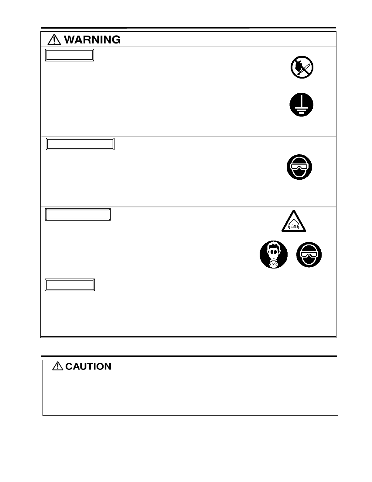
Safety precautions
Fire and explosion
1. Spark and open flames are strictly prohibited.
Paints can be highly flammable and can cause fire.
Avoid any ignition sources such as smoking, open flames, electrical goods, etc.
2. Never use the following HALGOGENATED HYDROCARBON SOLVENTS
which can cause cracks or dissolution on gun body (aluminum) by chemical reaction.
・unsuitable solvents:methyl chloride, dichloromethane, 1.2-dichloroethane,carbon tetrachloride,
(Be sure that all fluids and solvents are compatible with gun parts.
We are ready to supply a material list used in the product)
3. Securely ground spray gun by using air hose with built-in ground wire.
Ground wire : Less than 1MΩ. Check the earth stability periodically.
If not, insufficient grounding can cause fire and explosion due to static electric sparking.
Improper use of equipment
1. Never point gun toward people or animal.
If done, it can cause inflammation of eyes and skin or bodily injury.
2. Never exceed maximum operating pressure and
3. Be sure to release air and fluid pressures before cleaning, disassembling or servicing.
If not, remaining pressure can cause bodily injury due to improper operation or scattering cleaning liquid.
In order to release pressure, first stop supply of compressed air, fluid and thinner to spray gun.
Then remove fluid adj. knob and pull fluid needle set toward you.
4. Tip of fluid needle set has a sharp point. .
Do not touch the tip of fluid needle during maintenance for the protection of the human body.
Protection of human body
1.Use in a well-ventilated site by using spray booth.
If not, poor ventilation can cause organic solvent poisoning and catch fire.
2.Always wear protective gear (safety glasses, mask, gloves).
If not, cleaning liquid, etc., can cause inflammation of eyes and skin.
If you feel something wrong with eyes or skin, immediately see a doctor.
3.Wear earplugs if necessary.
Noise level can exceed
4.If operators pull the trigger many times during operation, it may cause carpal tunnel syndrome.
Be sure to take a rest if you feel tired.
Other precautions
1.Never alter this spray gun.
If done, it can cause insufficient performance and failure.
2.Enter working areas of other equipment (robots, reciprocators, etc.) after machines are turned off.
If not, contact with them can cause injury.
3.Never spray foods or chemicals through this gun.
If done, it can cause accident by corrosion of fluid passages or adversely affect health by mixed foreign matter.
4.If something goes wrong, immediately stop operation and find the cause. Do not use again until you have solved the problem.
trichloroethylene, 1.1.1-trichloroethane
maximum operating T emperature.
85dB
(A), depending on operating conditions and painting site
■
How to connect
-Use clean air filtered through air dryer and air filter. ・・・If not, dirty air can cause painting failure.
-When you use this gun for the first time after purchasing, adjust fluid needle packing set.
Slowly tighten fluid packing seat and loosen a bit when fluid needle set does not return smoothly, and adjust so that fluid needle set smoothly
moves.
-If you use this gun for the first time after purchasing, clean fluid passages spraying thinner and remove rust preventive oil.
If not, remaining preventive oil can cause painting failure such as fish eyes.
-Firmly fix hose or container to spray gun.
Job1. Connect an air hose to air nipple tightly.
Job2. Connect an applicable cup to fluid nipple tightly.
Job3. Flush the gun fluid passage with a compatible solvent.
Job4. Pour paint into container, test spray and adjust fluid output as well as pattern width
・・・
If not, disconnection of hose and drop of container can cause bodily injury.
- 2 -

■
How to operate
Recommended paint vis cos ity di ffers acco rdin g to pai nt proper ty and
painting conditions. 12 to 20 sec ./Ford cu p#4 is rec om menda ble.
Keep fluid output as small as possible to the extent that the job will
not be hindered. It will lead to better finishing with fine atomization.
Set the spray distance from the gun to the work piece as near as
possible within the range of 50- 150m m( 2~5.9 in) As this gun is
operated at low air pressur e, high tra nsfer effici ency wil l not be obtai ned
if the spray distanc e is too far .
■
Maintenance
Pulling the trigger of the gun wi th the patter n adj. S et and ful ly ope ned adj ust th e air regul ator in the spr ay
booth to obtain 0.5~1.0 bar ( 7~14 PSI) at the gun inl et as i ss ued on sp ecif ica tions table ah ead.
In this way the gun will atomi ze withi n 0.7 bar (10 P SI) insi de air cap.
NOTE
Using air hose 12m(39.4ft) long , the inne r diam eter mus t be a m inim um 8 mm (0.31 5 in) s o the gun can
have the correct air volume to atomize at 0.7 bar (10 PSI) inside air cap.
and inspection
The gun should be held so that it i s pe rpendi cul ar to the sur face of the wo rk piece at all ti m es. Th en, the
gun should move i n a s tr ai gh t an d hor iz on tal lin e. A r c i ng the g un c a us e s u ne v en p ain ti ng.
-First release air and pressure fully according to item No. 3 of “Improper use of equipment” of WARNING on page 2.
-Tip of fluid needle set has a sharp point. Do not touch the tip of needle valve at the maintenance for protection of the human body.
-Be careful not to damage the tip of fluid nozzle or must not put your hand on it.
-Only an experienced person who is fully conversant with the equipment can do maintenance and inspection.
-Never use commercial or other parts instead of ANEST IWATA original spare parts.
-
Never immerse the whole gun into liquid such as thinner.
-Never damage holes of air cap a fluid nozzle and fluid needle.
Step-by-step procedure
1.Pour remaining paint to an other contain er. Clean fluid passages and air cap set..
Spray a small amount of thinner to clean fl uid pass age s.
2.Clean each section with brus h soak ed wi th thinne r and wi pe out with waste c loth.
3. Before disassembly, fully clean fluid passages. 3. During disassembly, do not scratch seat section.
(1)Disassemble flui d noz zle.
(2)Disassemble flui d needl e set.
You do not need to remove fluid adj. guide set from gun body. Remove fluid adj. knob
and fluid needle spring, and then pull out fluid needle spring, and then pull out fluid
needle set from back of fluid adj. gui de se t..
4.To adjust fluid needle packing set, while keeping fluid needle set inserted, tighten fluid
needle packing seat by ha nd and then ti ghten fu rther by s panner .
5.In order to assemble air valve, first assemble air valve & air valve spring & fluid adj.
guide set together. Next, insert fluid needle set into fluid adj. guide set , then fit it to
gun body set and screw fluid ad j. guid e set.
6.Turn pattern adj. knob or air adj. knob counterclockwise to fully open. And then
tighten pattern adj. set or air adj. s et..
Where to inspect Parts replacem ent s tandar d
1. Each hole passage of air cap and fl uid no zz le
2. Packing and O ring
3.Leakage from seat section between fluid nozzle and fluid needle set Replace them if leakage does not s top after ful ly cle aning fluid nozzle and fluid needle set.
■
Parts list
When ordering parts, spec ify gun’ s m odel , part nam e with r ef. No. and mar ke d No. of air c ap
set, fluid nozzle and fluid needle.
When replacing fluid noz zle or /and fl uid ne edle fo r pres su re fe ed
application, please order noz zle ne edle s et.
1. Incomplete cleaning can fail patter n sha pe and uni form par ticl es.
Especially cl ean full y an d prom ptly two- com pone nt paint a fter use .
2. Do not immerse the whole gun in thinner. If done, it can damage parts.
When cleaning, never sc ratch eac h hole of air c ap set an d fluid nozzl e, and fl uid need le set.
(1)Remove fluid nozzle after removing fluid needle set or while keeping fluid needle pulled, in
order to protect seat section.
(2) Be careful when handing tip of fluid nee dle s et sinc e it is sha rp.
Disassemble fluid adj. guide s et as littl e as pos si ble.
4.Too much tightening of fluid needle packing set can cause bad mo ve me n t of flu i d n e ed l e se t
and fluid leakage from the ti p of flui d need le s et..
5. If you try to fit air valve spring and air valve to gun body set without fluid needle set, air
valve will not be fitted correctly and lop packing inside fluid adj. guide set will be
damaged.
6. If pattern adj. Knob or air adj. Knob is not fully opened, tip of it can contact and damage
fluid nozzle and cause s eizu re of th read.
Replace if it is crushed or deformed.
Replace if it is deform ed o r worn out.
If you replace fluid nozzle or fluid needle set only, fully match them and confirm that there is
no leakage.
- 3 -
Important
Fluid nozzle-fluid needle set combination
Fluid nozzle Fluid needle set
OrificeΦmm(in)
φ0.4(0.016)
φ
0.6(0.024)
φ
0.8(0.032)
φ
1.0(0.039)
φ1.2(0.047)
Mark Mark
04
06
08
10
12
Ⅰ
Ⅱ
Ⅲ

Parts list
No.
◆
◆
◆
8-1 Fluid nipple 1
8-2 Air nipple 1
10 Air valve seat set 1
10-1 O ring 1
11 Air valve seat screw 1
◆
12 Air valve 1
Description Q’ty
1 Air cap
2 Packing 1
3 Cover 1
4 Fluid nozzle 1
5 Fluid needle set 1
6 needle packing set 1
7 Needle packing seat 1
8 Gun body set 1
9
Pattern adj. set
1
1
No. Description Q’ty
13 Air valve spring 1
14 Fluid adj. guide 1
15 Fluid needle sp ring 1
16 Fluid adj. knob 1
17 Air valve shaft 1
◆
18 Air adj. set 1
19 Trigger stud 1
20 Trigger 1
21 E stopper 2
22 Brush 1
23 Instruction manual 1
◆
Marked parts are wearable parts.
■
Troubleshooting
Spray Pattern Problems Remedies
1. Air enters betw een fl uid nozz le an d tape red s eat of gu n body.
Fluttering
Crescent
Inclined
Split
Heavy Center
Spit
Problem
Air leaks
(from tip of air cup)
Paint leaks
Paint does not flow Tip of gun
2. Air is drawn from flui d needl e pac ki ng se t..
3.Air enters at fluid conta iner fitting nut or fl uid hos e joi nt.
1. Paint buildup on air cap par tiall y clogs hor n holes .
Air pressure from both horns differs.
1. Paint buildup or damage on fluid nozzle circumference and air cap
center.
2. Fluid nozzle is not pro perl y fitted .
1. Paint viscosity too low.
2. Fluid output too high.
1. Paint viscosity is too high.
2. Fluid output is too low.
1. Fluid nozzle and fluid needle set are not seated properly.
2.The first-stage travel of trigger (when only air dischar ges ) dec reas es.
3. Paint buildup insid e air cap s et.
Where it
occurred
Air valve * Dirt or damage on seat
Air valve set
Fluid nozzle
Fluid needle
Air valve seat set
O ring * Damage or deteriorate d
Fluid nozzle~
Fluid nozzle~gun body
Fluid needle~packing set
Needle packing set ~ needle set
Packing seat * Insufficient tightening
Fluid adj. knob * Insufficient opening ○
Tip hole of nozzle * Clogged ○
Paint filter * Clogged ○ ○
1. Remove fluid nozzle to clea n sea t. If it is damaged, replace nozzle.
2. Tighten fluid needle packing.
3. Fully tighten joint section.
1. Remove obstructions from horn holes with attached brush.
1. Remove obstructions.
2. Remove fluid nozzle and c lean s eat s ecti on.
1. Add paint to increase viscosity.
2. Tighten fluid adj. knob to reduce fluid output.
1. Add thinner to reduce viscosity.
2.Turn fluid adj.valve kn ob co unter-c l ockw is e to incr ease fluid ou tput.
1. Clean or replace fluid nozzle and fluid needle set.
2. Replace fluid nozzle and fluid needle set.
3. Clean air cap set.
Parts to be checked Cause
* Dirt or damage on seat ○ ○
* Wear on air valve spri ng
* Dirt, damage, wear on seat
fluid needle set
* Loose fluid needle adj. knob ○
* Wear on needle spring ○
* Insufficient tightening ○
* Dirt or damage on seat ○
* Needle does not return due to pac ki ng set to o ti ght ○ ○
* Needle does not return due to pai nt bu ild up on fl uid needle
* Wear ○ ○
But do not use metal objects to c lean ho rn ho les.
Replace if damaged.
Or turn pattern adj. valve set clockwise.
R1:retighten R2:adjust R3 : clean R4 : replace parts
Remedy
R1 R2 R3 R4
○ ○
○
○
○ ○
○
○ ○
○
- 4 -
Code No.03757530
No.T067-01
 Loading...