

Anest Iwata DDP 120 B WB.TE, DDP 90 E, DPS 120 C.TE, DPS 120 CN.TE, DPS 120 C WB.TE Instruction, Use And Maintenance Manual
...
Instruction Use and Maintenance Manual
GB
DIAPHRAGM PUMP SET
DDP 120 B Series
DDP 120 B.TE (Aluminium)
DDP 120 BN.TE (Stainless Steel)
DDP 120 B WB.TE (Anodized Aluminium)
DPS 120 C Series
DPS 120 C.TE (Aluminium)
DPS 120 CN.TE (Stainless Steel)
DPS 120 C WB.TE (Anodized Aluminium)
DDP 90 E Series
DDP 90 E.TE (Aluminium)
DDP 90 EN.TE (Stainless Steel)
DDP 90 E WB.TE (Anodized Aluminium)
DPS 90 G Series
DPS 90 G.TE (Aluminium)
DPS 90 GN.TE (Stainless Steel)
DPS 90 G WB.TE (Anodized Aluminium)
This ANEST-IWATA diaphragm paint pump complies to ATEX regulations 94/9/EC.
Protection level: II 2 GX Suitable for use in Zones 1 and 2.
X marking:
Any static electricity discharge from the pump is to be diverted to the ground through
the grounding wire which is included in this product.

CONTENTS
USE OF THE MANUAL ………………………………………………………………………………………3
WARRANTY ……………………………………………………………………………………………………3
1. SAFETY WARNING …………………………………………………………………………………………4
2. TRANSPORT AND HANDLING ……………………………………………………………………………6
2.1 TRANSPORT …………………………………………………………………………………………………6
2.2 TRANSPORT WITH CARDBOARD PACKAGING ………………………………………………………6
2.3 HANDLING ……………………………………………………………………………………………………6
2.4 TEMPORARY STORAGE ……………………………………………………………………………………7
2.5 CHECK ON THE PURCHASED PRODUCT ………………………………………………………………7
3. PRODUCT IDENTIFICATION ………………………………………………………………………………8
3.1 PLATE DATA …………………………………………………………………………………………………8
4. THECNICAL SPECIFICATIONS ……………………………………………………………………………9
4.1 DPS MODELS DIMENSIONS & WEIGHTS ………………………………………………………………9
4.2 DPS_MODELS ……………………………………………………………………………………………… 10
4.3 SAFETY SYSTEMS ……………………………………………………………………………………… 12
4.4 SAFETY PICTOGRAMS ………………………………………………………………………………… 12
4.5 WORKABLE PRODUCTS ………………………………………………………………………………… 13
5. PUMP OPERATION ……………………………………………………………………………………… 14
5.1 OPERATION DESCRIPTION …………………………………………………………………………… 15
6. INSTALLATION AND STARTING ……………………………………………………………………… 15
6.1 CONDITIONS FOR INSTALLATION …………………………………………………………………… 15
6.2 INSTALLATION …………………………………………………………………………………………… 15
6.3 INSTALLATIONS OF DPS MODELS …………………………………………………………………… 16
7. USE …………………………………………………………………………………………………… 19
7.1 USE …………………………………………………………………………………………………… 19
7.2 SAFETY RULES DURING USE ………………………………………………………………………… 19
7.3 CLOTHES …………………………………………………………………………………………………… 19
7.4 PREWASH ………………………………………………………………………………………………… 19
7.5 STARTING ………………………………………………………………………………………………… 20
7.6 DAILY INTERRUPTIONS ………………………………………………………………………………… 20
7.7 WRONG AND DANGEROUS USES …………………………………………………………………… 21
7.8 PRESSURE RELEASE PROCESS ……………………………………………………………………… 22
8. MAINTENANCE AND INSPECTIONS …………………………………………………………………… 23
8.1 GENERAL NOTES ………………………………………………………………………………………… 23
8.2 SAFETY RULES DURING MAINTENANCE …………………………………………………………… 23
8.3 RECOMMENDED SCHEDULED OPERATIONS ……………………………………………………… 23
8.4 DIAPHRAGM PUMP DISASSEMBLY FROM IT BASE SUPPORT ………………………………… 23
8.5 LID, CONNECTOR &AIR OPERATING VALVE DISASSEMBLY …………………………………… 24
8.6 DIAPHRAGM SET DISASSEMBLY ……………………………………………………………………… 24
8.7 DIAPHRAGM SET REASSEMBLY ……………………………………………………………………… 24
8.8 INTAKE AND EXHAUST VALVE DISASSEMBLY …………………………………………………… 25
8.9 INTAKE AND EXHAUST VALVE REASSEMBLY …………………………………………………… 25
8.10
PAINT REGULATOR MAINTENANCE, DISASSEMBLY & ASSEMBLY
8.11
PAINT REGULATOR SPARE PARTS
8.12 PAINT FILTER MAINTENANCE ………………………………………………………………………… 27
9. TROUBLE SHOOTING …………………………………………………………………………………… 28
10. SPARE PARTS LIST ……………………………………………………………………………………… 31
10.1 DPS DIAPHRAGM PUMP SET ASSEMBLY …………………………………………………………… 31
10.2 DDP DIAPHRAGM SPARE PARTS LIST ……………………………………………………………… 32
10.3 AIR OPERATING VALVE SPARE PARTS LIST ……………………………………………………… 33
10.4 PAINT FILTER SET ……………………………………………………………………………………… 34
10.5 AIR REGULATOR SET …………………………………………………………………………………… 34
10.6 ACCESSORIES …………………………………………………………………………………………… 34
10.7 SUCTION HOSE, SUCTION PIPE & DRAIN HOSE ………………………………………………… 35
10.8 2-WAY REGULATOR SET ……………………………………………………………………………… 35
11 DISMALTING ……………………………………………………………………………………………… 36
11.1 EQUIPMENT STORAGE ………………………………………………………………………………… 36
11.2 DISMALTING ……………………………………………………………………………………………… 36
2
……………………………………………………………………… 27
…………………………………… 26

Use of the This use and maintenance manual is an integral part of the equipment and must be easily available
Manual to the staff in charge of its use and maintenance. The user and the personnel in charge of mainte-
nance must be aware of the contents of this manual.
Read the manual carefully before starting ANY ACTIVITY involving the equipment, including its
handling. For easier references the instruction manual has been divided into the following sections:
WARNING
THE ORIGINAL CONFIGURATION OF THE EQUIPMENT MUST NOT BE CHANGED.
Upon receiving the equipment make sure that:
- The supply corresponds to the order specications.
- In case of non-compliance, inform our Technical Service immediately.
WARNING
ALL RIGHTS ARE RESERVED. THE REPRODUCTION OF ANY PART OF THIS MANUAL, IN ANY
FORM, IS STRICTLY FORBIDDEN WITHOUT PRIOR WRITTEN AUTHORIZATION OF THE
MANUFACTURING COMPANY.
Warranty All the products of ANEST IWATA Srl have a one-year warranty from invoice date, unless otherwise
stated in writing. The warranty covers all manufacturing faults and material defects. Any spare part
replacement or repair operation is covered only if it is carried out by our technicians at our servicing
shops.
The warranty covers no intervention of our technicians during installation or dismantling operations.
If for practical purposes one of our technicians is sent to the premises, the time plus extra for tra
velling and expenses will be invoiced at current prices. Our warranty does not cover direct or indirect
damage to people or property caused by our equipment. It covers no repair operations carried out by
the customer or by a third party, either.
THE WARRANTY DOES NOT COVER:
- Damage or breakdown caused by improper use or assembly.
- Damage or breakdown caused by the use of spare parts different from the original or recommen ded ones.
- Damage or breakdown caused by bad preservation.
- Components subject to wear (described in the spare parts list).
WARRANTY FORFEITURE:
- In case of delayed payment or other breaches of contract.
- Whenever changes or repairs are carried out on our equipment without our prior authorisation.
- Whenever the serial number is damaged or removed.
- When the damage is caused by improper use or functioning, or if the equipment falls, is bumped or
by other causes not due to normal working conditions.
- Whenever the unit is disassembled, tampered with or repaired without the authorisation of
ANEST IWATA S.r.l.
All repair interventions carried out under warranty do not interrupt its duration.
All disputes will be settled in the court of justice of Turin.
3
1. SAFETY WARNING
• Be sure to read and understand this instruction manual. The operator shall be fully conversant
with the requirements stated within this instruction manual including important warnings, cau tions and operations.
• Wrong operation (mishandling) can cause serious bodily injury, death, re or explosion.
SAFETY FACTOR
• Pay special attention to items which are shown by the below marks and symbols.
WEAR PROTECTIVE GEAR
During painting, be sure to wear protective gear such as glasses, mask or gloves
to avoid serious injury caused by paints or solvents which might enter your eyes
or you might inhale.
BE CAREFUL ABOUT VENTILATION
Use it in a well-ventilated area. Painting or cleaning in a narrow area with insufficient ventilation
can cause organic solvent intoxication or explosion due to sprayed mist of paint or solvent which
catches re.
If you feel any abnormality during operation, consult a medical doctor immediately.
CONTACT IS FORBIDDEN
If paint leaks, never try to stop it by hand. In that case please proceede as follows:
1. Follow the instructions about relaese pressure procedure, provided in section 7.8.
2. Check the leackage causes.
3. Replace or repair the faulty component.
BE CAREFUL ABOUT BODILY INJURY
Paint can enter human body directly through eyes, mouth or skin. It is very dangerous. If you feel
any abnormality or receive any injury, consult a medical doctor immediately.
LIMIT OF FLUID TO BE USED
Do not use it for food products.
KEEP AWAY FROM ORIGINS OF EXPLOSIONS OR FIRES
Never use near sparks or open re. Especially the following will cause re
• Open ames such as cigarettes, pipes.
• Electric goods such as stoves, lamps or heates.
4
CONNECT GROUNDING
Securely ground pump, spray gun, workpieces and containers containing paint or solvent.
Be sure to use ground wire set supplied with pump set.
Connect it to ground to have continuous grounding.
Insufficient grounding will cause explosion or re if exposed to a spark of electricity.
BE CAREFUL ABOUT EXPLOSION
Be sure to use paint pump at less than max. uid working pressure (section 4.).
Use at more than max. uid operating pressure can cause explosion of pump resulting in great
danger.
Never bend hose with a radius of less than 50mm. Never put heavy things on it (in order not to
damage the hose). If done, hose can explode causing great danger.
Securely connect hose to avoid leak and looseness. If hose is disconnected during operation,
hazardous hose movement and paint ejection will cause severe bodily injury.
Never use cracked, damaged, bent, crushed or distorted hose. Leakages from such a hose can
cause great danger during operation.
WARNING!
Never alter the equipment
When you replace parts, be sure to use our genuine parts. If not done, it can cause insufficient
performance or failure.
Install or keep pump free from rain or splashes. If not done, it can cause pump failure
Install pump on a horizontal surface
Install pump free of paint mist. Attached paint mist etc., can cause pump failure
Use clean air ltered through dryer and lter (ner than 50 microns).If not done, it can cause pump
failure.
* We shall not be responsible for any injury or damage caused by disregard of warnings, cau-
tions or instructions.
IMPORTANT
5
2. TRANSPORT AND HANDLING
2.1 TRANSPORT
To transport the equipment only the systems described below can be used. In any case make sure that
the transport and lifting device can bear the weight of the equipment with its packaging.
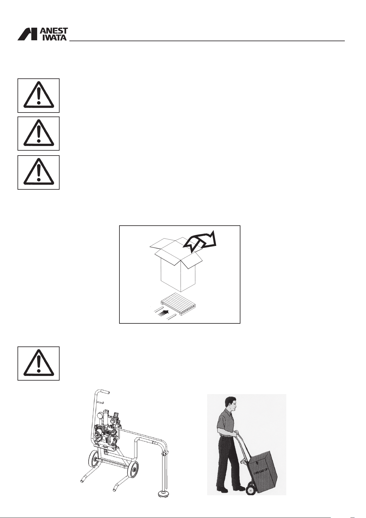
WARNING
ALWAYS KEEP THE PACKAGING IN VERTICAL POSITION.
WARNING
IT IS ADVISABLE THAT THE STAFF IN CHARGE OF HANDLING THE EQUIPMENT WEAR
PROTECTIVE GLOVES AND SAFETY SHOES.
WARNING
WHILE LIFTING OR HANDLING THE EQUIPMENT OR ANY OF ITS COMPONENTS CLEAR THE
WORKING AREA. LEAVE ALSO A SUFFICIENT SAFETY AREA AROUND THE EQUIPMENT TO
AVOID DAMAGING PEOPLE OR OBJECTS WHICH COULD BE THERE.
2.2 TRANSPORT WITH CARDBOARD PACKAGING
The equipment is put inside a cardboard packaging and wrapped with some shockproof material.
2.3 HANDLING
WARNING
FOLLOW THE INSTRUCTIONS ON THE PACKAGING BEFORE HANDLING AND OPENING IT.
HANDLING BY MEANS OF HANDLE HANDLING BY MEANS OF TROLLEY
6
To handle the cardboard packaging use a trolley.
2.4 TEMPORARY STORAGE
In case of storage, make sure the equipment is not put in places with an excessive humidity.
During transport and storage make sure the temperatures between 0 and 40° C are not exceeded.
2.5 CHECK ON THE PURCHASED PRODUCT
or storage. Also check that all standard components are inside the packaging.
When you receive and before using the pump, make sure it has not been damaged during transport
Stand Cart
All Models
Tank Wall
PR-5BL 1
Drain hose set 1
*Cart set - 1 - -
Supply lid - - 1 -
Hose band 3 3 - 3
Suction hose set with lter 1 1 - 1
Dip tube with lter - - 1 -
**Gravity hopper set - 1 - -
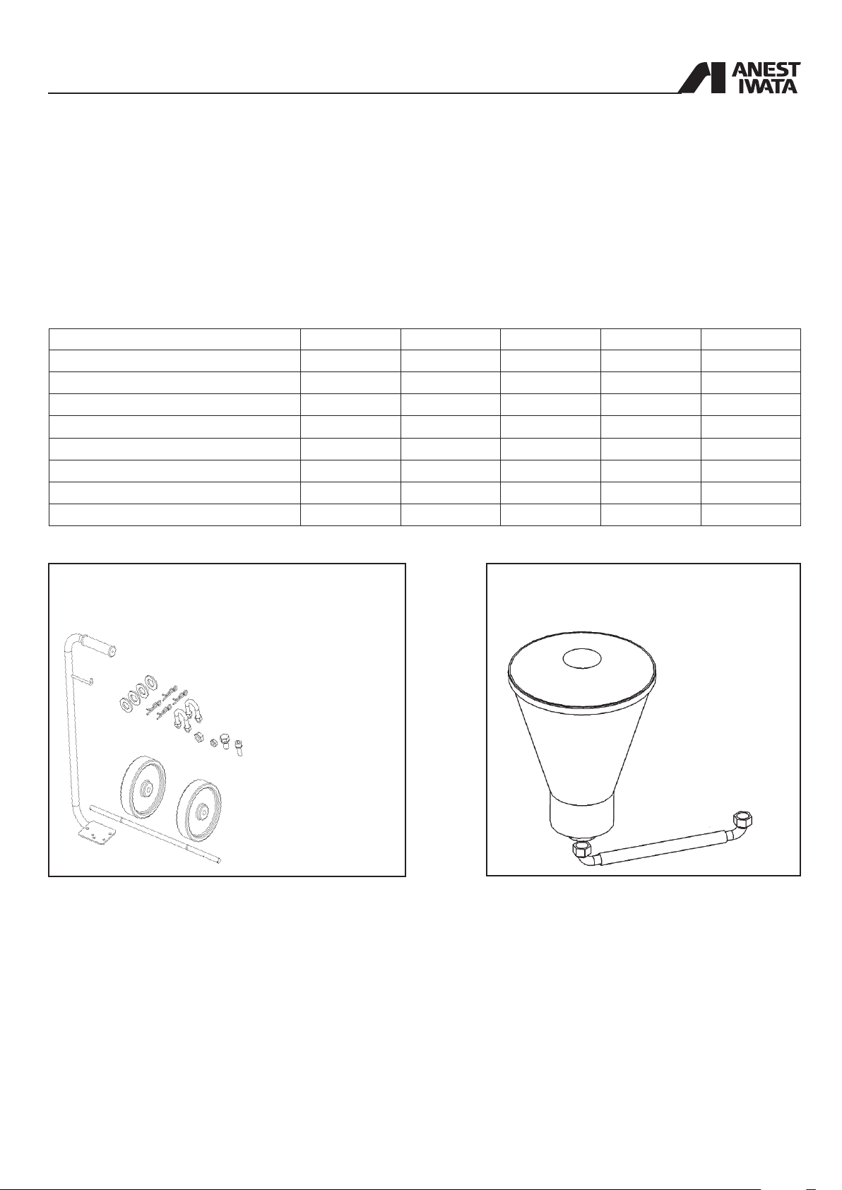
* Cart set 1 Handle
4 Washer
4 Snap pin
2 + 4 “U” Bolt _ Hex. nut
1 Bolt with Hex. hole (M6)
1 Bolt with Hex. hole (M8)
1 Axle
2 Solid tire
1 Hex. nut (M6)
1 Hex. nut (M8)
** Hopper set 1 Gravity hopper
1 Suction hose
7
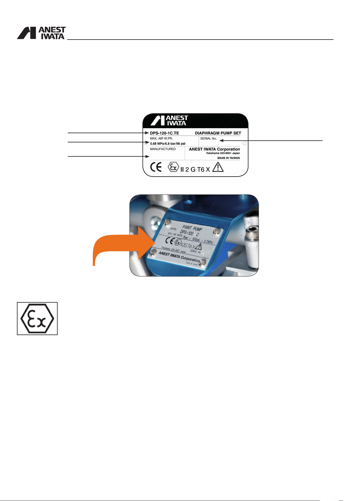
3. PRODUCT IDENTIFICATION
3.1 PLATE DATA
The manufacturer’s identication plate is applied on the diaphragm pump (see picture below).
It must not be removed at all, even if the equipment is resold. For any communication with the manu facturer always mention the serial number written on the plate itself.
Model
Max air working pressure
Construction year
The case of DPS 120-1C.TE
Serial number
• Equipment group : II
• Category: Gas 2G (Suitable for use in zones 1 and 2)
• Max. surface temperature: temperature class T6
• X marking : Any static electricity discharge from the pump is to be diverted to the ground through
the grounding wire which is included in this product.
8

4. TECHNICAL SPECIFICATIONS
Pump Version DPS-120C.TE DPS-90G.TE
PUMP Type DDP-120B DDP-120BN DDP-120B-WB DDP-90E DDP-90EN DDP-90E-WB
Paint Passages Aluminum
Air Working
Pressure Range
Stainless
Steel
Anodized
Aluminum
22~100 psi
Aluminum
1.5~7 bar
Stainless
Steel
Anodized
Aluminum
Max. Fluid
Working Pressure
Air Inlet G 1/4”
Fluid Outlet G 3/8”
Fluid Inlet G 1/2”
Paint Delivery
at 30 cyc/min
Paint Delivery
at 200 cyc/min
4.5 lt./min 1.5 lt./min
30lt./min 10lt./min
Paint viscosity
Working
Temperature
Compressor
(required power)
Noise Level 70 dB(A) 68 dB(A)
0.4~1.5 kW 0.4~0.75 kW
7 bar (100 psi)
85sec/Ford#4
5~40°C
4.1 DPS MODELS DIMENSIONS and WEIGHT
STAND TYPE TANK MOUNT TYPE
Dimensions (L_W_H) [mm]
DPS-120-1C.TE
DPS-120-1CN.TE
DPS-120-1C-WB.TE
DPS-90-1G.TE
DPS-90-1GN.TE
DPS-90-1G-WB.TE
409x358x806
409x358x764
Weight [kg]
10.5
13.9
10.5
9.6
11.7
9.6
DPS-120-2C.TE
DPS-120-2CN.TE 12.1
DPS-120-2C-WB.TE 9.6
DPS-90-2G.TE
DPS-90-2GN.TE 10.8
DPS-90-2G-WB.TE 8.7
Dimensions (L_W_H) [mm]
357x312x798
357x312x756
Weight [kg]
9.6
8.7
CART TYPE WALL MOUNT TYPE
Dimensions (L_W_H) [mm]
DPS-120-3C.TE
DPS-120-3CN.TE
DPS-120-3C-WB.TE
DPS-90-3G.TE
DPS-90-3GN.TE
DPS-90-3G-WB.TE 12.1 DPS-90-4G-WB.TE 8.6
437x452x868
437x452x868
Weight [kg]
13.0
15.5
13.0
12.1
14.2
DPS-120-4C.TE
DPS-120-4CN.TE 12.0
DPS-120-4C-WB.TE 9.5
DPS-90-4G.TE
DPS-90-4GN.TE 10.7
Dimensions (L_W_H) [mm]
363x214x534
363x214x492
Weight [kg]
9.5
8.6
CART TYPE (with Hopper)
Dimensions (L_W_H) [mm]
DPS-120-36C.TE
DPS-120-36CN.TE 15.5
DPS-120-36C-WB.TE 13.0
DPS-90-36G.TE
DPS-90-36GN.TE 14.2
DPS-90-36G-WB.TE 12.1
526x528x868
526x528x868
Weight [kg]
13.0
12.1
9
4.2 DPS_MODELS
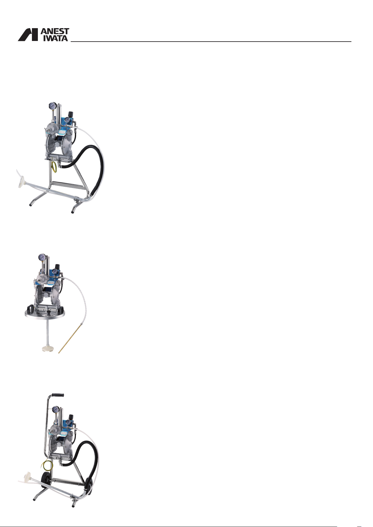
STAND TYPE
DPS 120-1C.TE/CN.TE/C-WB.TE
DPS 90-1G.TE/GN.TE/G-WB.TE
valve with exhaust hole.
• PR-5BL paint regulator for DPS 120-1C.TE and DPS 90-1G.TE
• PR-5BLN paint regulator for DPS 120-1CN.TE and DPS 90-1GN.TE
• PR-5BL WB paint regulator for DPS 120-1C-WB.TE and DPS 90-1G-WB.TE
DDP version mounted on stand, with paint regulator, 2 air regulators (for pump and
gun), paint lter unit, dip tube with lter, uid recirculation, 1 overpressure valve, ball
TANK TYPE
DPS 120-2C.TE/CN.TE/C-WB.TE
DPS 90-2G.TE/GN.TE/G-WB.TE
recirculation, overpressure valve, ball valve with exhaust hole.
DDP version mounted on Tank mount lid (without tank) with paint regulator, 2 air
regulators (for pump and gun), paint lter unit, dip pipe with lter (for 20L tank), uid
• PR-5BL paint regulator for DPS 120-2C.TE and DPS 90-2G.TE
• PR-5BLN paint regulator for DPS 120-2CN.TE and DPS 90-2GN.TE
• PR-5BL WB paint regulator for DPS 120-2C-WB.TE and DPS 90-2G-WB.TE
CART TYPE
DPS 120-3C.TE/CN.TE/C-WB.TE
DPS 90-3G.TE/GN.TE/G-WB.TE
ball valve with exhaust hole.
• PR-5BL paint regulator for DPS 120-3C.TE and DPS 90-3G.TE
• PR-5BLN paint regulator for DPS 120-3CN.TE and DPS 90-3GN.TE
• PR-5BL WB paint regulator for DPS 120-3C-WB.TE and DPS 90-3G-WB.TE
DDP version mounted on wheel cart with paint regulator, 2 air regulators (for pump
and gun), paint lter unit, dip tube with lter, uid recirculation, 1 overpressure valve,
10
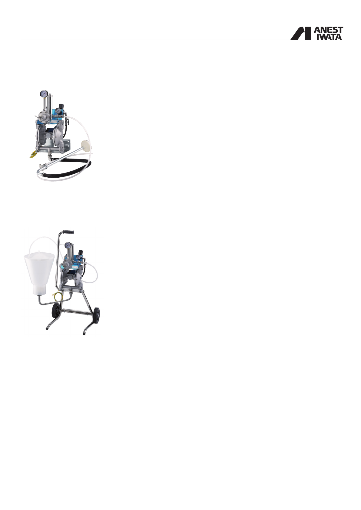
WALL MOUNT TYPE
DPS 120-4C.TE/CN.TE/C-WB.TE
DPS 90-4G.TE/GN.TE/G-WB.TE
sure valve, ball valve with exhaust hole.
• PR-5BL paint regulator for DPS 120-4C.TE and DPS 90-4G.TE
• PR-5BLN paint regulator for DPS 120-4CN.TE and DPS 90-4GN.TE
DDP version mounted on wall mounting bracket with paint regulator, 2 air regulators
(for pump and gun), paint lter unit, dip tube with lter, uid recirculation, 1 overpres-
• PR-5BL WB paint regulator for DPS 120-4C-WB.TE and DPS 90-4G-WB.TE
CART TYPE (with Hopper)
DPS 120-36C.TE/CN.TE/C-WB.TE
DPS 90-36G.TE/GN.TE/G-WB.TE
1 overpressure valve, ball valve with exhaust hole.
• PR-5BL paint regulator for DPS 120-36C.TE and DPS 90-36G.TE
• PR-5BLN paint regulator for DPS 120-36CN.TE and DPS 90-36GN.TE
• PR-5BL WB paint regulator for DPS 120-36C-WB.TE and DPS 90-36G-WB.TE
DDP version mounted on wheel cart with paint regulators, 2 air regulators (for pump
and gun), paint lter unit, plastic hopper (6 lt. with 50 mesh lter), uid recirculation,
11
 Loading...