

Anest Iwata DDP 120 B WB.TE, DDP 90 E, DPS 120 C.TE, DPS 120 CN.TE, DPS 120 C WB.TE Instruction, Use And Maintenance Manual
...
Instruction Use and Maintenance Manual
GB
DIAPHRAGM PUMP SET
DDP 120 B Series
DDP 120 B.TE (Aluminium)
DDP 120 BN.TE (Stainless Steel)
DDP 120 B WB.TE (Anodized Aluminium)
DPS 120 C Series
DPS 120 C.TE (Aluminium)
DPS 120 CN.TE (Stainless Steel)
DPS 120 C WB.TE (Anodized Aluminium)
DDP 90 E Series
DDP 90 E.TE (Aluminium)
DDP 90 EN.TE (Stainless Steel)
DDP 90 E WB.TE (Anodized Aluminium)
DPS 90 G Series
DPS 90 G.TE (Aluminium)
DPS 90 GN.TE (Stainless Steel)
DPS 90 G WB.TE (Anodized Aluminium)
This ANEST-IWATA diaphragm paint pump complies to ATEX regulations 94/9/EC.
Protection level: II 2 GX Suitable for use in Zones 1 and 2.
X marking:
Any static electricity discharge from the pump is to be diverted to the ground through
the grounding wire which is included in this product.

CONTENTS
USE OF THE MANUAL ………………………………………………………………………………………3
WARRANTY ……………………………………………………………………………………………………3
1. SAFETY WARNING …………………………………………………………………………………………4
2. TRANSPORT AND HANDLING ……………………………………………………………………………6
2.1 TRANSPORT …………………………………………………………………………………………………6
2.2 TRANSPORT WITH CARDBOARD PACKAGING ………………………………………………………6
2.3 HANDLING ……………………………………………………………………………………………………6
2.4 TEMPORARY STORAGE ……………………………………………………………………………………7
2.5 CHECK ON THE PURCHASED PRODUCT ………………………………………………………………7
3. PRODUCT IDENTIFICATION ………………………………………………………………………………8
3.1 PLATE DATA …………………………………………………………………………………………………8
4. THECNICAL SPECIFICATIONS ……………………………………………………………………………9
4.1 DPS MODELS DIMENSIONS & WEIGHTS ………………………………………………………………9
4.2 DPS_MODELS ……………………………………………………………………………………………… 10
4.3 SAFETY SYSTEMS ……………………………………………………………………………………… 12
4.4 SAFETY PICTOGRAMS ………………………………………………………………………………… 12
4.5 WORKABLE PRODUCTS ………………………………………………………………………………… 13
5. PUMP OPERATION ……………………………………………………………………………………… 14
5.1 OPERATION DESCRIPTION …………………………………………………………………………… 15
6. INSTALLATION AND STARTING ……………………………………………………………………… 15
6.1 CONDITIONS FOR INSTALLATION …………………………………………………………………… 15
6.2 INSTALLATION …………………………………………………………………………………………… 15
6.3 INSTALLATIONS OF DPS MODELS …………………………………………………………………… 16
7. USE …………………………………………………………………………………………………… 19
7.1 USE …………………………………………………………………………………………………… 19
7.2 SAFETY RULES DURING USE ………………………………………………………………………… 19
7.3 CLOTHES …………………………………………………………………………………………………… 19
7.4 PREWASH ………………………………………………………………………………………………… 19
7.5 STARTING ………………………………………………………………………………………………… 20
7.6 DAILY INTERRUPTIONS ………………………………………………………………………………… 20
7.7 WRONG AND DANGEROUS USES …………………………………………………………………… 21
7.8 PRESSURE RELEASE PROCESS ……………………………………………………………………… 22
8. MAINTENANCE AND INSPECTIONS …………………………………………………………………… 23
8.1 GENERAL NOTES ………………………………………………………………………………………… 23
8.2 SAFETY RULES DURING MAINTENANCE …………………………………………………………… 23
8.3 RECOMMENDED SCHEDULED OPERATIONS ……………………………………………………… 23
8.4 DIAPHRAGM PUMP DISASSEMBLY FROM IT BASE SUPPORT ………………………………… 23
8.5 LID, CONNECTOR &AIR OPERATING VALVE DISASSEMBLY …………………………………… 24
8.6 DIAPHRAGM SET DISASSEMBLY ……………………………………………………………………… 24
8.7 DIAPHRAGM SET REASSEMBLY ……………………………………………………………………… 24
8.8 INTAKE AND EXHAUST VALVE DISASSEMBLY …………………………………………………… 25
8.9 INTAKE AND EXHAUST VALVE REASSEMBLY …………………………………………………… 25
8.10
PAINT REGULATOR MAINTENANCE, DISASSEMBLY & ASSEMBLY
8.11
PAINT REGULATOR SPARE PARTS
8.12 PAINT FILTER MAINTENANCE ………………………………………………………………………… 27
9. TROUBLE SHOOTING …………………………………………………………………………………… 28
10. SPARE PARTS LIST ……………………………………………………………………………………… 31
10.1 DPS DIAPHRAGM PUMP SET ASSEMBLY …………………………………………………………… 31
10.2 DDP DIAPHRAGM SPARE PARTS LIST ……………………………………………………………… 32
10.3 AIR OPERATING VALVE SPARE PARTS LIST ……………………………………………………… 33
10.4 PAINT FILTER SET ……………………………………………………………………………………… 34
10.5 AIR REGULATOR SET …………………………………………………………………………………… 34
10.6 ACCESSORIES …………………………………………………………………………………………… 34
10.7 SUCTION HOSE, SUCTION PIPE & DRAIN HOSE ………………………………………………… 35
10.8 2-WAY REGULATOR SET ……………………………………………………………………………… 35
11 DISMALTING ……………………………………………………………………………………………… 36
11.1 EQUIPMENT STORAGE ………………………………………………………………………………… 36
11.2 DISMALTING ……………………………………………………………………………………………… 36
2
……………………………………………………………………… 27
…………………………………… 26

Use of the This use and maintenance manual is an integral part of the equipment and must be easily available
Manual to the staff in charge of its use and maintenance. The user and the personnel in charge of mainte-
nance must be aware of the contents of this manual.
Read the manual carefully before starting ANY ACTIVITY involving the equipment, including its
handling. For easier references the instruction manual has been divided into the following sections:
WARNING
THE ORIGINAL CONFIGURATION OF THE EQUIPMENT MUST NOT BE CHANGED.
Upon receiving the equipment make sure that:
- The supply corresponds to the order specications.
- In case of non-compliance, inform our Technical Service immediately.
WARNING
ALL RIGHTS ARE RESERVED. THE REPRODUCTION OF ANY PART OF THIS MANUAL, IN ANY
FORM, IS STRICTLY FORBIDDEN WITHOUT PRIOR WRITTEN AUTHORIZATION OF THE
MANUFACTURING COMPANY.
Warranty All the products of ANEST IWATA Srl have a one-year warranty from invoice date, unless otherwise
stated in writing. The warranty covers all manufacturing faults and material defects. Any spare part
replacement or repair operation is covered only if it is carried out by our technicians at our servicing
shops.
The warranty covers no intervention of our technicians during installation or dismantling operations.
If for practical purposes one of our technicians is sent to the premises, the time plus extra for tra
velling and expenses will be invoiced at current prices. Our warranty does not cover direct or indirect
damage to people or property caused by our equipment. It covers no repair operations carried out by
the customer or by a third party, either.
THE WARRANTY DOES NOT COVER:
- Damage or breakdown caused by improper use or assembly.
- Damage or breakdown caused by the use of spare parts different from the original or recommen ded ones.
- Damage or breakdown caused by bad preservation.
- Components subject to wear (described in the spare parts list).
WARRANTY FORFEITURE:
- In case of delayed payment or other breaches of contract.
- Whenever changes or repairs are carried out on our equipment without our prior authorisation.
- Whenever the serial number is damaged or removed.
- When the damage is caused by improper use or functioning, or if the equipment falls, is bumped or
by other causes not due to normal working conditions.
- Whenever the unit is disassembled, tampered with or repaired without the authorisation of
ANEST IWATA S.r.l.
All repair interventions carried out under warranty do not interrupt its duration.
All disputes will be settled in the court of justice of Turin.
3
1. SAFETY WARNING
• Be sure to read and understand this instruction manual. The operator shall be fully conversant
with the requirements stated within this instruction manual including important warnings, cau tions and operations.
• Wrong operation (mishandling) can cause serious bodily injury, death, re or explosion.
SAFETY FACTOR
• Pay special attention to items which are shown by the below marks and symbols.
WEAR PROTECTIVE GEAR
During painting, be sure to wear protective gear such as glasses, mask or gloves
to avoid serious injury caused by paints or solvents which might enter your eyes
or you might inhale.
BE CAREFUL ABOUT VENTILATION
Use it in a well-ventilated area. Painting or cleaning in a narrow area with insufficient ventilation
can cause organic solvent intoxication or explosion due to sprayed mist of paint or solvent which
catches re.
If you feel any abnormality during operation, consult a medical doctor immediately.
CONTACT IS FORBIDDEN
If paint leaks, never try to stop it by hand. In that case please proceede as follows:
1. Follow the instructions about relaese pressure procedure, provided in section 7.8.
2. Check the leackage causes.
3. Replace or repair the faulty component.
BE CAREFUL ABOUT BODILY INJURY
Paint can enter human body directly through eyes, mouth or skin. It is very dangerous. If you feel
any abnormality or receive any injury, consult a medical doctor immediately.
LIMIT OF FLUID TO BE USED
Do not use it for food products.
KEEP AWAY FROM ORIGINS OF EXPLOSIONS OR FIRES
Never use near sparks or open re. Especially the following will cause re
• Open ames such as cigarettes, pipes.
• Electric goods such as stoves, lamps or heates.
4
CONNECT GROUNDING
Securely ground pump, spray gun, workpieces and containers containing paint or solvent.
Be sure to use ground wire set supplied with pump set.
Connect it to ground to have continuous grounding.
Insufficient grounding will cause explosion or re if exposed to a spark of electricity.
BE CAREFUL ABOUT EXPLOSION
Be sure to use paint pump at less than max. uid working pressure (section 4.).
Use at more than max. uid operating pressure can cause explosion of pump resulting in great
danger.
Never bend hose with a radius of less than 50mm. Never put heavy things on it (in order not to
damage the hose). If done, hose can explode causing great danger.
Securely connect hose to avoid leak and looseness. If hose is disconnected during operation,
hazardous hose movement and paint ejection will cause severe bodily injury.
Never use cracked, damaged, bent, crushed or distorted hose. Leakages from such a hose can
cause great danger during operation.
WARNING!
Never alter the equipment
When you replace parts, be sure to use our genuine parts. If not done, it can cause insufficient
performance or failure.
Install or keep pump free from rain or splashes. If not done, it can cause pump failure
Install pump on a horizontal surface
Install pump free of paint mist. Attached paint mist etc., can cause pump failure
Use clean air ltered through dryer and lter (ner than 50 microns).If not done, it can cause pump
failure.
* We shall not be responsible for any injury or damage caused by disregard of warnings, cau-
tions or instructions.
IMPORTANT
5
2. TRANSPORT AND HANDLING
2.1 TRANSPORT
To transport the equipment only the systems described below can be used. In any case make sure that
the transport and lifting device can bear the weight of the equipment with its packaging.
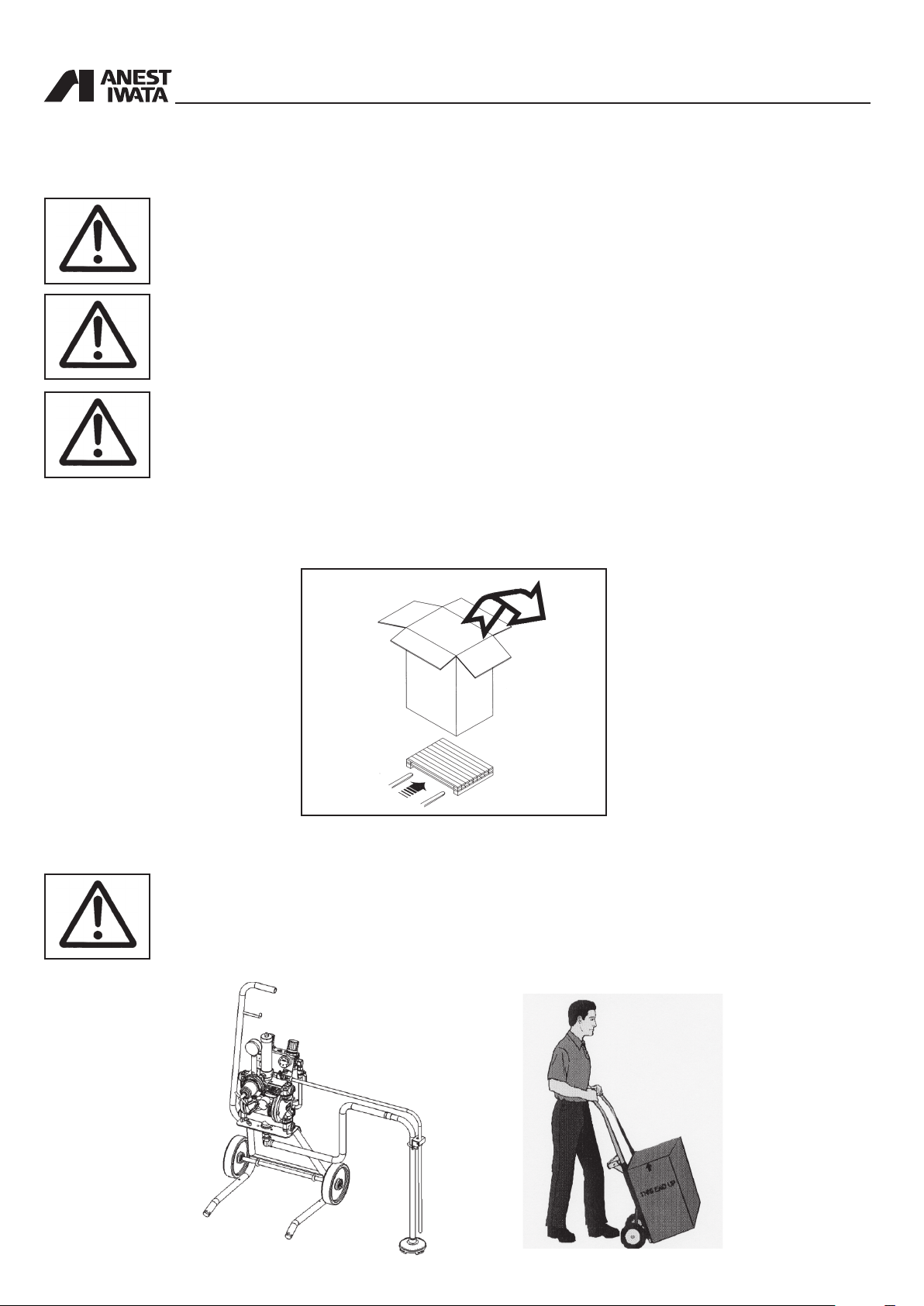
WARNING
ALWAYS KEEP THE PACKAGING IN VERTICAL POSITION.
WARNING
IT IS ADVISABLE THAT THE STAFF IN CHARGE OF HANDLING THE EQUIPMENT WEAR
PROTECTIVE GLOVES AND SAFETY SHOES.
WARNING
WHILE LIFTING OR HANDLING THE EQUIPMENT OR ANY OF ITS COMPONENTS CLEAR THE
WORKING AREA. LEAVE ALSO A SUFFICIENT SAFETY AREA AROUND THE EQUIPMENT TO
AVOID DAMAGING PEOPLE OR OBJECTS WHICH COULD BE THERE.
2.2 TRANSPORT WITH CARDBOARD PACKAGING
The equipment is put inside a cardboard packaging and wrapped with some shockproof material.
2.3 HANDLING
WARNING
FOLLOW THE INSTRUCTIONS ON THE PACKAGING BEFORE HANDLING AND OPENING IT.
HANDLING BY MEANS OF HANDLE HANDLING BY MEANS OF TROLLEY
6
To handle the cardboard packaging use a trolley.
2.4 TEMPORARY STORAGE
In case of storage, make sure the equipment is not put in places with an excessive humidity.
During transport and storage make sure the temperatures between 0 and 40° C are not exceeded.
2.5 CHECK ON THE PURCHASED PRODUCT
or storage. Also check that all standard components are inside the packaging.
When you receive and before using the pump, make sure it has not been damaged during transport
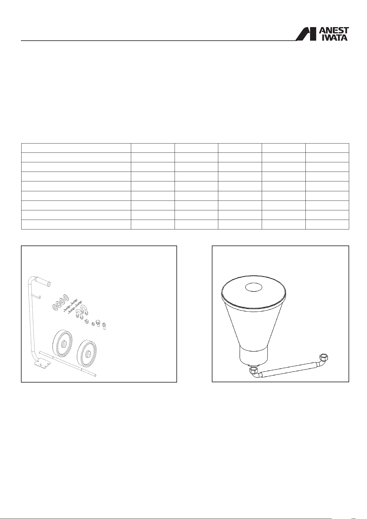
Stand Cart
All Models
Tank Wall
PR-5BL 1
Drain hose set 1
*Cart set - 1 - -
Supply lid - - 1 -
Hose band 3 3 - 3
Suction hose set with lter 1 1 - 1
Dip tube with lter - - 1 -
**Gravity hopper set - 1 - -
* Cart set 1 Handle
4 Washer
4 Snap pin
2 + 4 “U” Bolt _ Hex. nut
1 Bolt with Hex. hole (M6)
1 Bolt with Hex. hole (M8)
1 Axle
2 Solid tire
1 Hex. nut (M6)
1 Hex. nut (M8)
** Hopper set 1 Gravity hopper
1 Suction hose
7
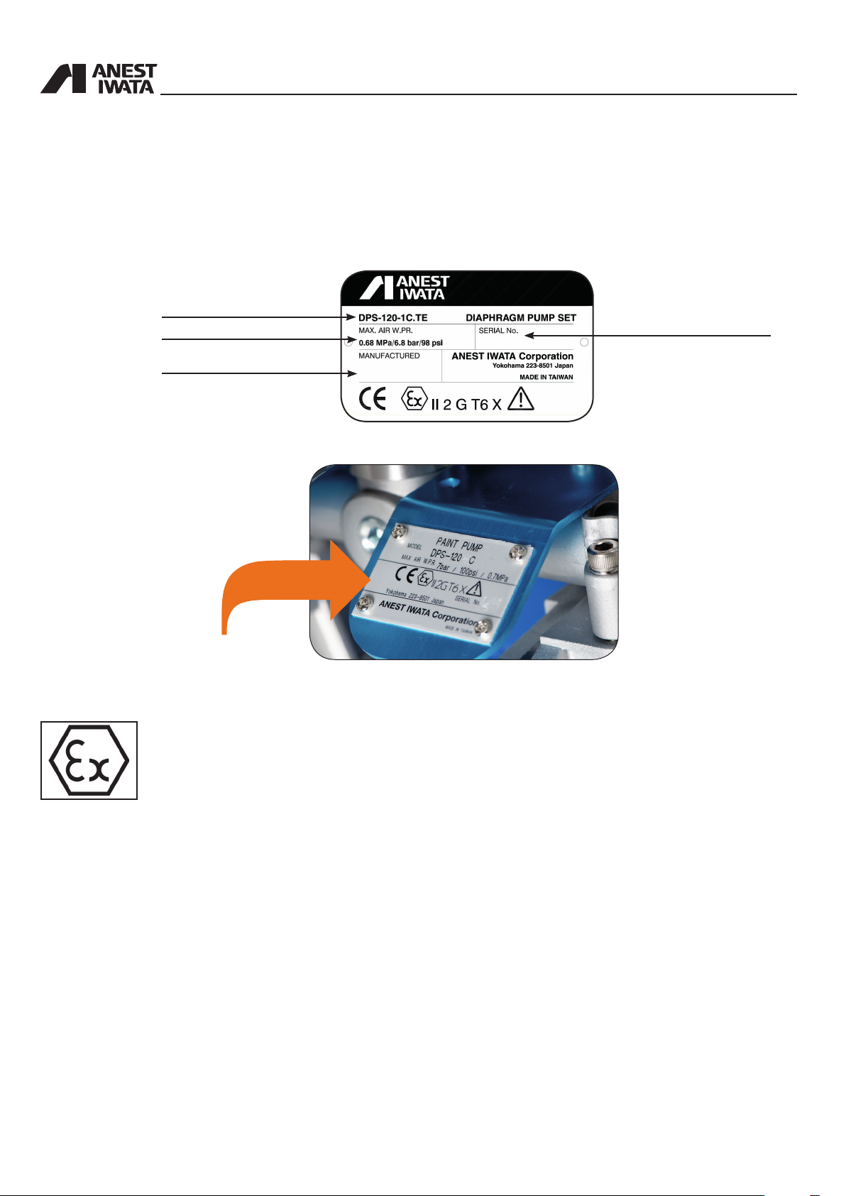
3. PRODUCT IDENTIFICATION
3.1 PLATE DATA
The manufacturer’s identication plate is applied on the diaphragm pump (see picture below).
It must not be removed at all, even if the equipment is resold. For any communication with the manu facturer always mention the serial number written on the plate itself.
Model
Max air working pressure
Construction year
The case of DPS 120-1C.TE
Serial number
• Equipment group : II
• Category: Gas 2G (Suitable for use in zones 1 and 2)
• Max. surface temperature: temperature class T6
• X marking : Any static electricity discharge from the pump is to be diverted to the ground through
the grounding wire which is included in this product.
8

4. TECHNICAL SPECIFICATIONS
Pump Version DPS-120C.TE DPS-90G.TE
PUMP Type DDP-120B DDP-120BN DDP-120B-WB DDP-90E DDP-90EN DDP-90E-WB
Paint Passages Aluminum
Air Working
Pressure Range
Stainless
Steel
Anodized
Aluminum
22~100 psi
Aluminum
1.5~7 bar
Stainless
Steel
Anodized
Aluminum
Max. Fluid
Working Pressure
Air Inlet G 1/4”
Fluid Outlet G 3/8”
Fluid Inlet G 1/2”
Paint Delivery
at 30 cyc/min
Paint Delivery
at 200 cyc/min
4.5 lt./min 1.5 lt./min
30lt./min 10lt./min
Paint viscosity
Working
Temperature
Compressor
(required power)
Noise Level 70 dB(A) 68 dB(A)
0.4~1.5 kW 0.4~0.75 kW
7 bar (100 psi)
85sec/Ford#4
5~40°C
4.1 DPS MODELS DIMENSIONS and WEIGHT
STAND TYPE TANK MOUNT TYPE
Dimensions (L_W_H) [mm]
DPS-120-1C.TE
DPS-120-1CN.TE
DPS-120-1C-WB.TE
DPS-90-1G.TE
DPS-90-1GN.TE
DPS-90-1G-WB.TE
409x358x806
409x358x764
Weight [kg]
10.5
13.9
10.5
9.6
11.7
9.6
DPS-120-2C.TE
DPS-120-2CN.TE 12.1
DPS-120-2C-WB.TE 9.6
DPS-90-2G.TE
DPS-90-2GN.TE 10.8
DPS-90-2G-WB.TE 8.7
Dimensions (L_W_H) [mm]
357x312x798
357x312x756
Weight [kg]
9.6
8.7
CART TYPE WALL MOUNT TYPE
Dimensions (L_W_H) [mm]
DPS-120-3C.TE
DPS-120-3CN.TE
DPS-120-3C-WB.TE
DPS-90-3G.TE
DPS-90-3GN.TE
DPS-90-3G-WB.TE 12.1 DPS-90-4G-WB.TE 8.6
437x452x868
437x452x868
Weight [kg]
13.0
15.5
13.0
12.1
14.2
DPS-120-4C.TE
DPS-120-4CN.TE 12.0
DPS-120-4C-WB.TE 9.5
DPS-90-4G.TE
DPS-90-4GN.TE 10.7
Dimensions (L_W_H) [mm]
363x214x534
363x214x492
Weight [kg]
9.5
8.6
CART TYPE (with Hopper)
Dimensions (L_W_H) [mm]
DPS-120-36C.TE
DPS-120-36CN.TE 15.5
DPS-120-36C-WB.TE 13.0
DPS-90-36G.TE
DPS-90-36GN.TE 14.2
DPS-90-36G-WB.TE 12.1
526x528x868
526x528x868
Weight [kg]
13.0
12.1
9
4.2 DPS_MODELS
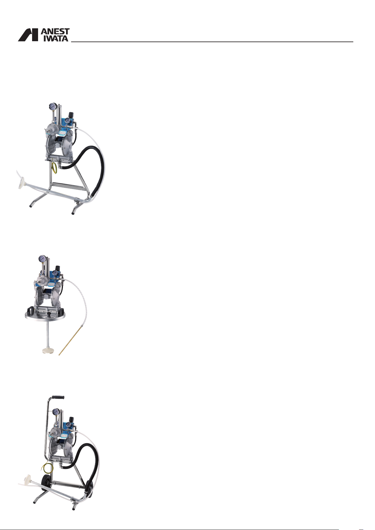
STAND TYPE
DPS 120-1C.TE/CN.TE/C-WB.TE
DPS 90-1G.TE/GN.TE/G-WB.TE
valve with exhaust hole.
• PR-5BL paint regulator for DPS 120-1C.TE and DPS 90-1G.TE
• PR-5BLN paint regulator for DPS 120-1CN.TE and DPS 90-1GN.TE
• PR-5BL WB paint regulator for DPS 120-1C-WB.TE and DPS 90-1G-WB.TE
DDP version mounted on stand, with paint regulator, 2 air regulators (for pump and
gun), paint lter unit, dip tube with lter, uid recirculation, 1 overpressure valve, ball
TANK TYPE
DPS 120-2C.TE/CN.TE/C-WB.TE
DPS 90-2G.TE/GN.TE/G-WB.TE
recirculation, overpressure valve, ball valve with exhaust hole.
DDP version mounted on Tank mount lid (without tank) with paint regulator, 2 air
regulators (for pump and gun), paint lter unit, dip pipe with lter (for 20L tank), uid
• PR-5BL paint regulator for DPS 120-2C.TE and DPS 90-2G.TE
• PR-5BLN paint regulator for DPS 120-2CN.TE and DPS 90-2GN.TE
• PR-5BL WB paint regulator for DPS 120-2C-WB.TE and DPS 90-2G-WB.TE
CART TYPE
DPS 120-3C.TE/CN.TE/C-WB.TE
DPS 90-3G.TE/GN.TE/G-WB.TE
ball valve with exhaust hole.
• PR-5BL paint regulator for DPS 120-3C.TE and DPS 90-3G.TE
• PR-5BLN paint regulator for DPS 120-3CN.TE and DPS 90-3GN.TE
• PR-5BL WB paint regulator for DPS 120-3C-WB.TE and DPS 90-3G-WB.TE
DDP version mounted on wheel cart with paint regulator, 2 air regulators (for pump
and gun), paint lter unit, dip tube with lter, uid recirculation, 1 overpressure valve,
10
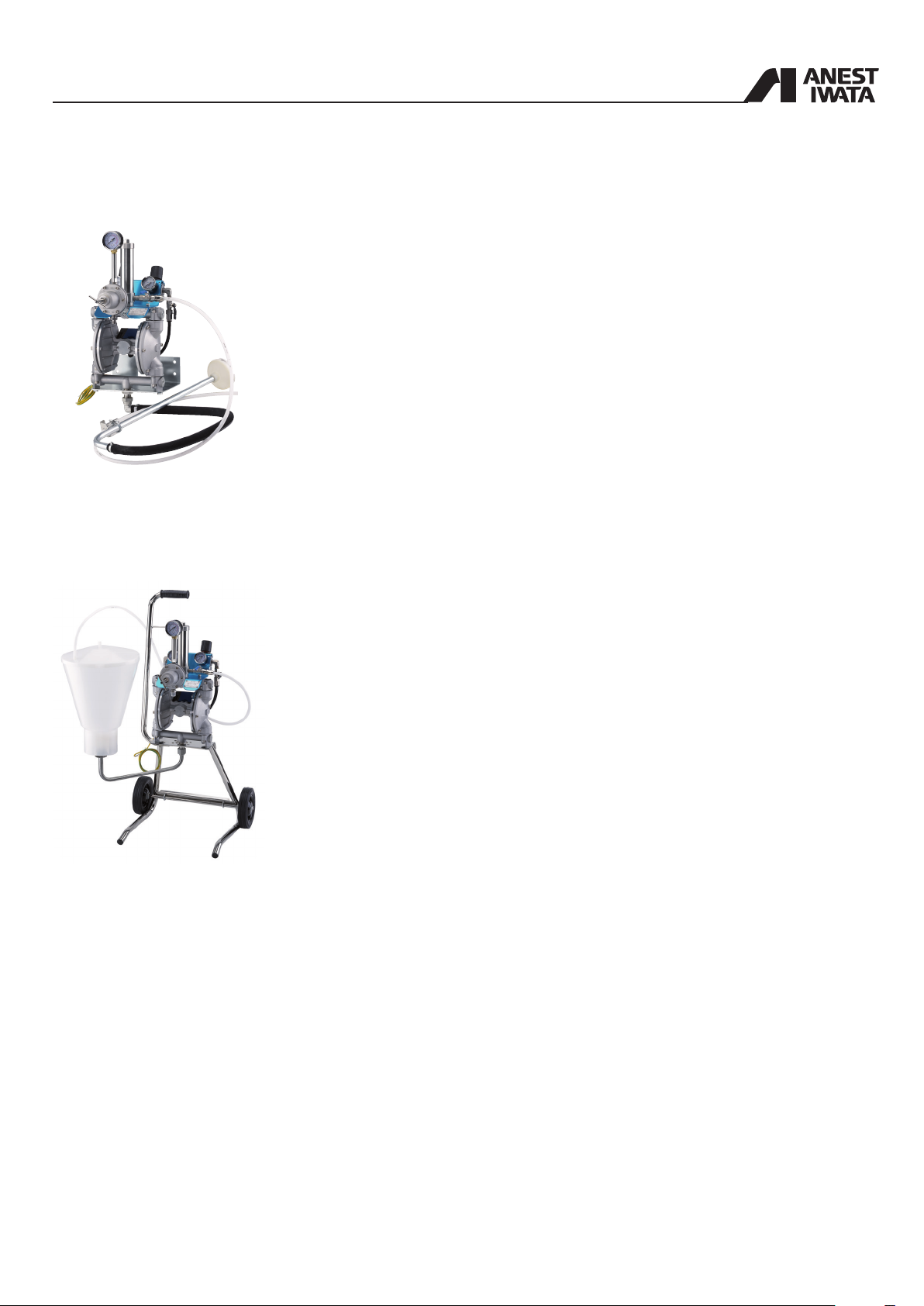
WALL MOUNT TYPE
DPS 120-4C.TE/CN.TE/C-WB.TE
DPS 90-4G.TE/GN.TE/G-WB.TE
sure valve, ball valve with exhaust hole.
• PR-5BL paint regulator for DPS 120-4C.TE and DPS 90-4G.TE
• PR-5BLN paint regulator for DPS 120-4CN.TE and DPS 90-4GN.TE
DDP version mounted on wall mounting bracket with paint regulator, 2 air regulators
(for pump and gun), paint lter unit, dip tube with lter, uid recirculation, 1 overpres-
• PR-5BL WB paint regulator for DPS 120-4C-WB.TE and DPS 90-4G-WB.TE
CART TYPE (with Hopper)
DPS 120-36C.TE/CN.TE/C-WB.TE
DPS 90-36G.TE/GN.TE/G-WB.TE
1 overpressure valve, ball valve with exhaust hole.
• PR-5BL paint regulator for DPS 120-36C.TE and DPS 90-36G.TE
• PR-5BLN paint regulator for DPS 120-36CN.TE and DPS 90-36GN.TE
• PR-5BL WB paint regulator for DPS 120-36C-WB.TE and DPS 90-36G-WB.TE
DDP version mounted on wheel cart with paint regulators, 2 air regulators (for pump
and gun), paint lter unit, plastic hopper (6 lt. with 50 mesh lter), uid recirculation,
11

4.3 SAFETY SYSTEMS
Several safety systems have been conceived during the diaphragm pump design and manufacture to
safeguard the operator, in compliance with pr EN 12621 Directive about paint.
SAFETY VALVE
A 7 bar calibrated safety valve is installed to ensure the pump working pressure does not exceed the
limits inside the feeding circuit.
If the calibration pressure is exceeded, the valve opens by releasing the excess of air.
RELEASING HOLE
WARNING
DO NOT DISASSEMBLE THE SAFETY VALVE. ANY TAMPERING WITH COULD BE DANGE ROUS FOR THE OPERATOR AND COMPROMISE THE EQUIPMENT GOOD WORKING.
EXHAUST VALVE
In case of anomalies during working, turn 90° the exhaust valve lever. In this way the air supply will
be interrupted and the residual pressure inside the pump will be released.
ON
OFF
4.4 SAFETY PICTOGRAMS
Some pictograms can be found on the pump with the safety warnings to follow by anyone who is
going to use it.
WARNING
THE MANUFACTURING COMPANY IS NOT TO BE HELD RESPONSIBLE FOR DAMAGE OR
ACCIDENTS TO PEOPLE OR THINGS COMING FROM THE NON-COMPLIANCE WITH THE
PRESCRIBED RULES.THE RESPONSIBILITY RESTS ENTIRELY WITH THE OPERATOR HIM
SELF.
12

4.5 WORKABLE PRODUCTS
All ANEST IWATA DPS diaphragm pumps are conceived to paint ferrous material in general, wood
and plastic.
The products that can be delivered are: solvent-based paints for all DPS-120C.TE - DPS-90G.TE
models with a maximum viscosity of 85 sec/Ford # 4 (100 sec/NK-2) and water based paint for all
DPS-120CN.TE/C-WB.TE - DPS-90GN.TE/G-WB.TE models.
To use the pump with special products ask for the manufacturer’s approval. Moreover, the pump
technical features will have to be adapted to the special product working.
The Company ANEST IWATA is not to be held responsible for any accident due to the pump use by
an UNAUTHORIZED and non qualied staff using it for purposes that are different from the above
mentioned ones.
WARNING
NEVER USE THE FOLLOWING HALOGENATED HYDROCARBON SOLVENTS :
- METHYL CHLORIDE, DICHLOROMETHANE, 1.2-DICHLOROETHANE, CARBON TETRA CHLORIDE, TRICHLOROETHYLENE,1.1.1-TRICHLOROETHANE WHICH CAN CAUSE
CRACKS OR DISSOLUTION ON GUN BODY (ALUMINUM) BY CHEMICAL REAC-
TIONS.
- ANY INFLAMMABLE OR VERY TOXIC PRODUCTS SUCH AS PETROL, KEROSENE,
INFLAMMABLE SOLVENTS OR COMBUSTIBLE GASES;
- ANY HERBICIDE OR PESTICIDE
- ANY RADIOACTIVE FLUID
(Be sure that all uids and solvents are compatible with gun parts. We are ready to supply a
material list used in the gun on request.)
Do not use with corrosive liquids (except for PH6-8)
13

5. PUMP OPERATION
5.1 OPERATION DESCRIPTION
Based on a simple manufacture, the operation consists in two diaphragm movement, which are both
xed at the end of a rod, pressurizing and sending the paint.
The compressed air enters the air chamber from side A in picture 1. The diaphragm is moved to the
left, by pushing the paint.
At the same time, the diaphragm on the opposite end (side B) moves to the left by sucking the paint.
When the rod is completely on the left, the double pneumatic valve reverses the operations.
The compressed air enters the air chamber from side B in picture 2. The diaphragm is moved to the
right, by pushing the paint.
At the same time, the diaphragm on side A end sucks the paint.
The pump repeats the above-mentioned suction and delivery movements. The result is a steady and
pulsation-free material ow.
The main feature is the action of two pneumatic valves: the rst one is a power valve feeding the
pump, and the other one a control valve always ensuring the movement.
FIG.1
FIG.2
Material outlet
A
Material outlet
A
Air outlet
B
Air inlet
Material suction
Air outlet
B
Air inlet
Material suction
14

6. INSTALLATION AND STARTING
6.1 CONDITIONS FOR INSTALLATION
The installer must know the ATEX classication of the installation area, as well as the risks coming
from a potentially explosive atmosphere, by paying attention to the explosion and re risks so as to
adopt the most suitable protections.
All maintenance, assembly and disassembly operations must be carried out by a qualied staff out
side the area at risk of explosion.
Also check that the accessories comply with the essential safety requirements of the ATEX directi ves. Handle them with great care to avoid changing their features.
Once installed, clean the unit.
The equipment must be installed by a specialized and authorized staff.
In any case, follow the instructions below.
WARNING
IF PAINTING IS CARRIED OUT OUTSIDE THE SPRAY BOOTH, ALWAYS OPERATE IN A PLACE
WITH A RIGHT VENTILATION TO AVOID CONCENTRATING INFLAMMABLE VAPOURS COMING
FROM SOLVENTS OR PAINTS.
6.2 INSTALLATION
- Place the pump on a stable surface, to avoid movements during use.
- The distance between the pump and the paint (height of suction) must be as short as possible.
However, it can vary according to viscosity and required delivery.
- Connect the air supply to the supply connection of the pump.
- The suction pipe must have an inside diameter of at least 1/2” or slightly higher.
- To install the pump use two M8x12 screws by means of the special holes on the lower adaptor.
Do not fasten the pump with any other system.
- Connect the free end of the GROUND WIRE directly.
WARNING
THE FLUIDS USED AND THE REQUIREMENTS MUST BE IN COMPLIANCE WITH SECTION 4.5
(WORKABLE PRODUCTS) AND WITH SECTION 7.0 (USE).
WARNING
- CONSULT THE LOCAL CODE FOR DETAILED INSTRUCTIONS RELATIVE TO GROUND
CONNECTIONS IN THE WORK AREA AND TO THE TYPE OF SYSTEM USED.
- THE GROUND WIRE (INCLUDED) MUST HAVE A MINIMUM SECTION EQUAL TO 1.5 mm2.
- ONE END OF THE CABLE MUST BE EARTHEN WHILE THE OTHER MUST BE CONNEC TED TO THE LATERAL LID OF THE DIAPHRAGM PUMP.
Bolt (M3)
Fasten the pump to the ground by means of the bracket welded on the trailer or on the stand.
15

6.3 INSTALLATION OF DPS_MODELS
A - STAND TYPE / CART TYPE
1. Remove the dust proof caps (B,E,F,H,I on page 21)
2. Detach the pump assembly from the support by removing Hex. Bolts (M8)
3. Flip the stand and assemble the pump assy to the right position.
Stand
Pump assy
Hex. Bolt (M8)
PAINT SUPPLY / Suction hose
1. Connect the suction hose to the paint inlet joint (H page 21).
2. Fix the drain hose to the suction hose with band (3 spots wherever you want).
1
COMMON
1. Connect the drain hose
to the two-way valve for
paint recirculation.
Drain Hose
2
Band 3 spots wherever
you want
Suction hose
B - TANK MOUNTING TYPE
1. Remove the dust proof caps (B,E,F,H,I on page 21)
2. Assemble the supply lid in its seat, connect the drain hose to the two-way valve for paint recirculation.
3. Connect the suction hose to the paint inlet joint. (Make sure the seal tape is taped around the suction hose)
Drain hose
Supply lid
(as COMMON 1)
16
Suction hose
Fix the drain hose
with the wing bolt.

C - CART TYPE
1. Assemble the following parts below in numerical order, and x them to the stand.
4. Washer
5. Snap pin*
3. Tire
2. Washer
Axle
1. Snap pin*
Hex. Nut
U bolt
* Put the end of the pin into axle hole, and
push it inside all the way by using hammer
As is when is tted
2. Unscrew from pump lower adaptor the tting bolt (M8) and assemble the handle on stand by using hex. bolt (M8)
and bolt with hex. hole (M6).
Bolt wit
hex. hole (M6)
CLOSE UP
Handle
Hex. Bolt (M8)
Hex. nut (M6)
Band 3 spots
wherever you want
Suction hose
17

D - WALL MOUNTING TYPE
1. Remove the dust proof caps (B,E,F,H,I on page 21)
2. Detach the pump assembly from bracket by removing hex. Bolts (M8)
3. Flip the bracket and assemble the pump to the right position on bracket by using hex. Bolts (M8).
4. Connect the drain hose to the two-way valve for paint recirculation. (as COMMON 1)
5. Connect the suction hose to the paint inlet joint.
Drain hose
Bracket
Suction hose
Hex. Bolt (M8)
Band 3 spots wherever you want
E - GRAVITY HOPPER TYPE
1. Assemble the hopper set by means the “U” suction tube, to the paint inlet joint of the pump mounted on cart.
2. Connect the drain hose from two-way valve for paint recirculation to hopper lid set directly.
Pump set
Drain hose
18

7. USE
7.1 USE
This section describes the diaphragm pump use in compliance with the safety standards in force.
Read this section carefully.
7.2 SAFETY RULES DURING USE
TO USE the diaphragm pump COMPLY WITH the safety precautions and rules described below.
The manufacturing company declines all responsibility if the operator does not comply with
them. It is not to be held responsible for any carelessness during the pump use, either.
If the system is used improperly, it could be broken by causing serious damage.
Do not change the system; use only Anest Iwata original spare parts.
Check the system daily: repair or replace immediately all worn or damaged parts.
Never exceed the maximum working pressure: 7 bar (100 psi)
IT IS FORBIDDEN to use the equipment for purposes that are different from the ones it is
destined to which are described in the use and maintenance manual. If in doubt, apply to your
Anest Iwata reseller.
Use paints and solvents compatible with the system parts they come in touch with.
Refer to the paint and solvent features mentioned by the manufacturer.
Wear the protective clothes described in section 7.3
Comply with all the local standards on electric safety and re risks.
7.3 Clothes
Wear some protective gloves and goggles, an oxygen mask and some ear protections during
working. Always follow the laws in force (Ex. LAW 626/94).
7.4 PREWASH
1. Make sure the pump is installed correctly (see section 6.3).
2. Soak the suction tube into the washing liquid, or ll the hopper or the tank according to the model
used.
3. Put the ball valve in the right position.
4. Adjust the inlet pressure between 2.0 and 7 bar.
5. Open gradually the two-way valve for paint recirculation (B on page 21). The washing liquid will
have to circulate through the dip tube recirculation pipe.
- If the Tank mount model is used, the washing liquid will circulate through the paint handling
system (JET STREAM).
- In the Hopper model, recirculation pipe is directly connected to the hopper.
6. Close the two-way valve for paint recirculation and adjust the paint pressure by means of Paint
Regulator (Recommended pressure for washing 3.0 bar)
7. Press the gun trigger (or supply the automatic gun opening control with some air), without
spraying air and let the washing uid circulate for some minutes.
8. Make sure the washing has been done and then discharge the pump residual liquid and stop it.
19

WARNING
THE PUMP MUST BE WASHED BEFORE USING IT FOR THE FIRST TIME, IF IT IS NOT
USED FOR A LONG TIME AND AFTER ANY COLOUR CHANGE.
7.5 STARTING
Before beginning working, start the pump by following the instructions below:
1. Connect ground wire set to ground.
2. For all models with suction pipe, dip it into the product tank to be pumped.
For the model with hopper, ll it with the product to be pumped.
For the models on tank, ll the product tank to be pumped.
3. Open the two-way valve for paint recirculation (Ref. B on page 21).
4. Lift and turn gradually the pressure reducer knob (Ref. C on page 21). Adjust it at a pressure sli ghtly higher than 2.0 bar, to enable the pump to release the air.
5. Close the two-way valve for paint recirculation (Ref. B on page 21) and release the air through
the gun, too.
6. Increase the pressure of the reducer connected to the pump (Recommended pressure about 5.0
bar).
7. Adjust the paint pressure regulator as required (from 0 to 3.0 bar).
8. Adjust the spraying air by means of the reducer (Ref. D on page 21) and test the gun on a
panel before using it.
PRECAUTIONS
b) When the paint level inside the tank decreases, the pump can suck some air. Increase
c) Do not drag the pump by pulling it by the pipes.
a) Use the gun under pressure.
the paint level.
PRECAUTIONS: EMERGENCY STOP
a) The material does not stop coming out from the gun.
b) Fluid discharge through the connectors or the damaged pipe. CLOSE THE EXHAUST
BALL VALVE
7.6 DAILY INTERRUPTIONS
1. When the pump is stopped:
- The air supply must not be disconnected if the interruption is short.
- If the interruption is long, turn the exhaust ball valve (A) discharge the air from the circuit and
When the pump must be stopped because of the following reasons:
open the recirculation valve (B), to release the residual uid pressure.
2. When the pump is stopped at the end of the working day:
- Wash the uid passages.
- Remove the dip tube lter and the lter inside the paint lter and clean it.
20

D
B
F
C
G
I
H
A) Exhaust Ball valve
B) Two-way valve for paint recirculation
C) Pump air pressure reducer
D) Gun air pressure reducer
E) Feeder line connection
F) Air connection to gun
G) Safety valve
H) Paint inlet joint
I) Paint pressure regulator
Dust proof cap (female) : B) , E) , F) , H) , I)
Tank mount model : H) is not included (Dust proof cap male)
7.7 WRONG AND DANGEROUS USES
A
E
A wrong earthing, an insufficient ventilation, a naked ame or a spark
can cause a re or an explosion and provoke some serious injuries.
WARNING
IF SOME SPARKS OR AN ELECTRIC DISCHARGE WERE PERCEIVED, INTERRUPT IMMEDIA TELY ALL PAINTING OPERATIONS.
DO NOT USE THE SYSTEM UNTIL THE PROBLEM CAUSE IS IDENTIFIED.
Keep away from the working area all kinds of waste, of solvent container, of solvent or petrol soaked
rags or clothes.
Before starting the system disconnect all the electrical connections inside the working area.
Before using the system switch off all the naked ames and pilot lights inside the working area.
Do not smoke inside the working area.
During painting operations, or if there are some vapours in the air, do not switch on or off the lights
inside the working area.
Do not use any petrol engine inside the working area.
Some organic solvents or discharged toxic vapours can enter the eyes or the skin, be swallowed or
inhaled, by provoking serious injuries.
When the air engine is running, keep the face away from the exhaust.
21

7.8 PRESSURE RELEASE PROCESS
WARNING
1. Close the air to the gun.
2. Close the air to the pump (exhaust ball valve).
3. Make sure the recirculation pipe is not clogged. Then open gradually the recirculation two-way
valve and leave it open.
4. Hold the gun tightly and lean it on the earthed metal container, pull the trigger to release the
PRECAUTIONS
1. To operate the pump, use some ltered air by means of an air lter with ltering section lower
than 50 µm. We recommend using a lter with condensate automatic discharge.
2. Do not make the pump idle.
3. Do not spray any paint or solvent towards the pump.
4. Do not install the pump near heat sources or in the sun. Put it far from sprinklings of water.
5. To avoid any problem after using bi-component paints, wash the pump immediately after using it
otherwise all uid passages could be clogged and the whole installation will have to be disassem bled.
pressure. If an automatic gun is used, supply the rod opening control with some air under pressure.
22

8. MAINTENANCE AND INSPECTION
8.1 GENERAL NOTES
A suitable maintenance is important for a longer duration of the equipment in good working condi tions and efficiency ensuring functional safety as time goes by.
All maintenance operations must be carried out by a qualied staff. The pump design and the mate rials used to manufacture it limit the maintenance interventions to a simple periodic cleaning.
The staff must be provided with the individual protections that are generally used for similar opera tions. They also must follow the safety rules described in section 8.2.
8.2 SAFETY RULES DURING MAINTENANCE
The main rules to follow during maintenance interventions on the unit are:
1. Disconnect the pneumatic supply before replacing any component.
2. Do not wear rings, watches, chains, bracelets, etc. during maintenance operations.
3. Always use the individual protections (gloves, safety shoes, etc.).
4. Do not use naked ames, points or pins for cleaning.
5. Do not smoke.
8.3 RECOMMENDED SCHEDULED OPERATIONS
Every 50 hours Disassemble and clean the delivery and suction lters as well as the uid passage ducts.
working hours Note: If highly pigmented paints or paints with many particles tending to deposit are used,
carry out maintenance operations at shorter intervals.
Every 2.000 Overhaul the whole painting unit and replace the worn components.
working hours Note: The component corrosion speed varies according to the type of paint and the working
conditions. To replace the worn components, follow the given instructions.
8.4 DIAPHRAGM PUMP DISASSEMBLY FROM ITS BASE SUPPORT
PRECAUTIONS
Before disassembling the pump, follow carefully the instructions below:
a) While disassembling the pump, avoid damaging the O’rings.
b) To disassemble and reassemble the adaptors (5-3) and the pump lids (2) use a 5 mm
Allen wrench and a 10 mm spanner.
c) Disassemble, in this order, the lower adaptor (5), the upper adaptor (3), the side lids (2)
by unscrewing the socket head screw by means of the suitable spanners.
1. Refer to the PRECAUTIONS FOR THE OPERATOR about the pressure release process (section 7.8).
2. Disconnect the pump from the compressed air supply.
3. Disassemble the suction lter system from the pump.
4. Remove the recirculation pipe.
5. Disassemble the paint regulator from the pump.
6. Disassemble the pump casing from the support base by removing the four special screws.
7. Remove the lower adaptor, the upper adaptor and the lid by following this order.
PRECAUTIONS
overturning the pressure regulator itself.
Some paint residues could remain inside the regulator: discharge them into the paint tank by
23

8.5 LID AND CONNECTOR AND AIR OPERATING VALVE DISASSEMBLY
Main body
Upper Adaptor
Lower Adaptor
Diaphragm
Lid
Rod
Bolt with hex. hole (M5)
O’rings
8.6 DIAPHRAGM SET DISASSEMBLY
A. Remove the two nuts with a 13mm spanner.
spanner, and loosen the nut with a 13mm span ner on the side where the diaphragm has not
been removed yet and disassemble as described
D. Hold at face of center of the rod with a 12mm
in point b).
B. Remove the following parts from rod:
- Nut
- Spring washer
- Diaphragm holder (out)
- O’ring
- Diaphragm set (outside/inside)
- Diaphragm holder (inside)
E. Remove the O rings and the “Y” packings
Rod
Diaphragm (out)
Diaphragm holder (in)
Y-packings
O’ring
Diaphragm (in)
O rings
Nut
Spring washer
Diaphragm holder (out)
C. Disassemble the rod by pressing on the screw
and by pulling from the opposite side-towards
the outside.
8.7 DIAPHRAGM SET REASSEMBLY
To reassemble reverse the disassembly
procedure.
Push
24
Rod
Main body

PRECAUTIONS
Pay attention to the assembly direction of the “Y” packings (see the picture).
A. Place the “Y” packings to the direction that they open outward.
B. Lubricate the “Y” packing, the O’ring and the slots with some lithium grease.
C. Tightening pressure of nuts : 8.83 Nm
8.8 INTAKE AND EXHAUST VALVE DISASSEMBLY
1. Press down the ball with a screwdriver
by using stopper of the lid to remove
the intake valve and the ball.
2. Remove the O’ring. Do not use any
metal tool to avoid scratching the
pump.
Ball
O’ring
Exhaust valve
3. Remove the ball on the exhaust valve
and pull the exhaust valve up with n-
ger.
4. Remove the O’ring. Do not use any
metal tool to avoid scratching the
pump.
Lid
Ball
O’ring
8.9 INTAKE AND EXHAUST VALVE REASSEMBLY
A. INTAKE VALVE
- Assemble the O ring on the valve.
- Insert the ball
- Insert the valve into its seat.
B. EXHAUST VALVE
- Assemble the O ring on the valve.
- Insert the valve into its seat.
- Insert the ball.
Stopper
Intake valve
PRECAUTIONS
During the reassembly of the lids on main body, do not reverse the delivery side with the suction one.
25

8.10 PR-5BL - PR-5BL WB - PR-5BL N PAINT REGULATOR MAINTENANCE,
DISASSEMBLY AND ASSEMBLY
IMPORTANT
When you disassemble main body, rising pipe and pressure gauge, apply sealing agent to
each threaded section to keep airtightness.
Whenever disassembling ball and seat of tungsten carbide, you have be sure to conrm that
there is no wear or damage. If there is any wear or damage, replace with new one.
DISASSEMBLING
1. Fully loosen handle set (22), and remove bolt with hex. hole (17), diaphragm cap (19),
spring stopper (20), adjusting spring (18) and diaphragm.
2. Loosen jam nut (7), and remove joint (1), valve spring (2), ball (3), seat (5) and packing (6).
3. Fix hex. section of diaphragm bolt (10), and remove hex. nut (16), spring washer (15),
diaphragm stopper (13), O ring (14), diaphragm (12) and diaphragm holder (11).
4. If O ring placed into joint is damaged or deformed, remove O ring from joint.
ASSEMBLING
1. Check on each section if there are damage and foreign matter .
2. Fit diaphragm holder (11), diaphragm (12), O ring (14), diaphragm holder (13) and spring
washer (15) into diaphragm bolt (10) and tighten hex. nut (16).Tightening torque of hex.
nut 9.8N-m
3. Mount diaphragm section, adjusting spring (18), spring stopper (20), and diaphragm cap
(19) on main body (8), and evenly tighten bolts with hex. bolt (17) diagonally.
4. Fit O ring (4) to joint (1).
5. Fit packing (6) and tungsten carbide seat (5) to body (8).
6. Fit valve spring (2) and ball (3) to joint (1), and then t joint (1) to body (8).
Tightening torque of joint 14.7N-m
7. Fix joint (1) with jam nut (7).
Fit tungsten carbide seat to main body so that tungsten carbide ball can be tted on tapered
side. Do not forget to t packing.
Wrong assembling can cause wrong movement of pointer of pressure gauge due to leakage
from seat, failing performance.
Pay attention to tightening torque when tting joint (1).
Too much tightening can damage main body.
Tightening torque of joint 14.7 N-m
When tting joint, pay attention that tungsten carbide ball does not slip out of the seat.
IMPORTANT
26

8.11 PR-5BL, PR-5BL WB, PR-5BLN PAINT REGULATOR SPARE PARTS
Ref. Description Qt.
1 Joint G3/8” 1
2 Valve spring 1
3 Carbide ball 1 #
4 O’ring 1
5 Carbide seat 1 #
6 Packing 1
7 Hex. Nut 1
8 Body 1
9 Joint G1/4”-G3/8” 1
10 Diaphragm bolt 1
11 Diaphragm holder 1
12 Diaphragm 1 #
13 Diaphragm stopper 1
14 O’ring 1 #
15 Spring washer 1
16 Hexagon nut 1
17 Hex. Socket bolt 1
18 Adjusting spring 1
19 Diaphragm cap 1
20 Spring stopper 1
21 Hexagon nut 1
22 Handle set 1
23 Rising pipe 1
24 Pressure gauge 1
Weight
PR-5BL /-5 BL WB PR-5BLN
850 g 1020 g
Max. ow 1.5 l/min
Max. primary pressure 7.0 bar
Pressure range 3.0 bar
Connection IN G 3/8”
Connection OUT G 3/8”
PR-5BL FOR MODELS (Body in Aluminium):
•
- DPS 120-1C/ DPS 90-1G
- DPS 120-2C/ DPS 90-2G
- DPS 120-3C/ DPS 90-3G
- DPS 120-4C/ DPS 90-4G
- DPS 120-36C/ DPS 90-36G
PR-5BL WB FOR MODELS (Body in Anodized Aluminium):
- DPS 120-1C-WB/ DPS 90-1G-WB
- DPS 120-2C-WB/ DPS 90-2G-WB
- DPS 120-3C-WB/ DPS 90-3G-WB
- DPS 120-4C-WB/ DPS 90-4G-WB
- DPS 120-36C-WB/ DPS 90-36G-WB
PR-5BLN (Body in Stainless Steel):
- DPS 120-1CN/ DPS 90-1GN
- DPS 120-2CN/ DPS 90-2GN
- DPS 120-3CN/ DPS 90-3GN
- DPS 120-4CN/ DPS 90-4GN
- DPS 120-36CN/ DPS 90-36GN
Parts subjects to wear: #
•
Marked parts differt amoung Aluminium,
Stainless Steel, Anodized Aluminium.
8.12 PAINT FILTER MAINTENANCE
If the pump is used correctly (that is it is washed carefully each time it is used), the paint lter needs
no special maintenance, with the exception of cleaning and lter replacement.
If there are some solidied paints inside the lter itself or inside the paint passages, disassemble it
completely, clean it carefully and reassemble it.
27

9. TROUBLESHOOTING
IMPORTANT
Spare parts marked by [#] must be ANEST IWATA original items.
If not, it can cause failure.
PROBLEMS CAUSES REMEDIES
a) The compressed air does not reach the a) Connect the compressed air.
pump air inlet
b) The air pressure is too low to start the pump b) Supply a sufficient air pressure restart
(minimum 2.0 bar)
c) The exhaust valve (A page 21) is in dischar- c) Turn the valve in the right position.
ging position
d) The air regulator is closed d) Open the air regulator.
The pump does e) The paint regulator closed e) Open the paint regulator
not work, it stops
or does not
restart. The following parts are clogged because of
solidied paint inside them?
a) Fluid lter inside the paint lter (10 page 34) a) Clean and replace the uid lter.
b) Every pump uid passage b) Remove the clogging material.
c) Every paint regulator uid passage c) Remove the clogging material.
Disassemble the pump and
check the following parts which
will be replaced if damaged:
a) PTFE diaphragm [#]
b) Rubber diaphragm [#]
c) “Y” packings (21) [#]
The pump does not run d) O ring. [#]
burrs). [#]
f) Self-lubricating bushings. [#]
g) Main casing inside diameters (Ø 15) damaged
(scratched or with burrs).
Replace the Air Opreating Valve.
f) The silencer (27 page 32) is clogged f) Replace the silencer.
e) Rod (any strange deformation,scratches or
28

PROBLEMS CAUSES REMEDIES
The following parts are unscrewed or damaged
a) The pump suction connector a) Check if some tightening are loosened
with the suction pipe and tighten them.
b) The suction connector b) Put some adhesive and tighten.
c) The lower adaptor c) Tighten.
d) The dip tube suction pipe d) If the suction pipe is damaged (it sucks air),
replace it.
The pressure regulator, the recirculation two-way Open the pressure regulator and then the
valve and the gun are closed? gun and the recirculation two-way valve
The pump works, The following parts are clogged with some
but the uid solidied paint residues?
does not a) The paint lter uid lter a) Clean and replace the lter.
come out b) The suction lter b) Clean and replace the lter.
c) The suction hose set c) Remove the solidied part.
d) All the pump uid passages d) Remove the solidied part.
e) All the paint regulator uid passages e) Remove the solidied part. [#]
The upper and lower balls are stuck? Clean the surfaces and release them. [#]
The ball inside the paint lter is stuck? Clean the surfaces and release it. [#]
The following parts are damaged or worn
a) The ball seats (exhaust and intake valves) a) Replace them. [#]
b) The balls b) Replace them. [#]
c) The O’rings of each ball seat c) Replace them. [#]
d) The PTFE diaphragms d) Replace them. [#]
The following parts are unscrewed or damaged?
a) The pump suction joint (31 page 32) a) Check the loosened tightening and tighten
with the suction pump them.
b) The suction joint (31 page 32) b) Put some adhesive and tighten.
The outgoing c) The lower adaptor c) Tighten.
paint contains d) The suction pipe of dip tube d) If the dip tube set is damaged (it sucks some
air. air), it must be replaced.
The nuts at the rod ends are loosened? Tighten them. [#]
The following parts are damaged?
a) Diaphragms a) Replace them. [#]
b) The O rings (23 page 32)) between the b) Replace them. [#]
PTFE diaphragm and the diaphragm seat
29

PROBLEMS CAUSES REMEDIES
Check air sources.
a) The air ow is interrupted by the air pipe bending a) Restore the air pipe
b) The air pressure is too low to start the pump b) Supply a sufficient air pressure
(minimum 2,0 bar).
c) The air regulator is closed c) Open the air regulator.
The uid The silencer (27) is clogged Replace it.
discharge The following parts are clogged with some
decreases solidied paint?
a) The lter inside the paint lter a) Clean and replace the lter.
b) The suction lter (of the dip tube) b) Clean and replace the lter.
c) The suction pipe (of the dip tube) c) Remove the solidied part.
d) All the pump material passages d) Remove the solidied part.
e) All the paint regulator material passages e) Remove the solidied part.
The following parts are damaged or worn?
a) The ball seats a) Replace them.
b) The balls (9) b) Replace them.
c) The PTFE diaphragms c) Replace them.
The paint regulator is closed? Open the paint regulator
PR-5BL , PR-5BL WB , PR-5BLN PAINT REGULATOR
PROBLEMS CAUSES REMEDIES
The pointer of a) Not properly seated, or foreign matter a) Clean and assemble again.
pressure gauge b) Wear or damage on seat b) Replace tungsten carbide seat(5) [#]
surpasses c) Wear and damage on ball c) Replace tungsten carbide ball(3) [#]
max. pressure. d) Seat packing (6) damaged d) Replace packing (6) [#]
a) Loose joint (1) a) Tighten
Paint leaks b) Loose bolt with hex. Hole (17) b) Tighten
outside c) Loose hex. nut (16) c) Tighten
d) Diaphragm damaged (12) d) Replace diaphragm [#]
e) O ring damaged (4) e) Replace O ring [#]
Secondary a) Primary pressure is too low a) Raise primary side pressure
pressure b) Failure of pressure gauge (24) b) Replace pressure gauge
does not rise c) Paint hardened in rising pipe (23) c) Clean paint out
Pressure a) Damage to valve spring (2) a) Replace valve spring (2) [#]
is unstable
30

10. SPARE PARTS LIST
10.1 DPS_DIAPHRAGM PUMP SET ASSEMBLY
Ref. Item
A Paint regulator set
B Air regulator set
C Paint lter set
E Swivel joint
F Hex. socket bolt with washer
G Connecting bolt
I Nipple
M Ball valve
N Joint
O Pipe
P Washer bolt
*1: for Stainless Steel
& Anodized Aluminium
*
B
31

10.2 DDP_DIAPHRAGM PUMP SPARE PARTS LIST
32

DDP_DIAPHRAGM PUMP SPARES PART LIST
Rif. Descrizione
1 Main body
2 Lid
3 Upper Adaptor
DDP 90 F DDP 120 B
•
•
•
1 1
2 2
1 1
4 Hexagon socket plug 4 4
5 Lower Adaptor
•
1 1
6 Packing set # 4 4
7 Exhaust valve # 2 2
8 O’ring set 4 4
9 Steel ball set # 4 4
10 Ground wire 1 1
11 Intake valve # 2 2
12 Hex. socket bolt with washer 12 12
13 Hex. socket bolt with washer 8 8
14 Air operating valve set 1 1
15 Hex. nut 2 2
16 Spring Washer 2 2
17 Diaphragm holder(outer) 2 2
18 Diaphragm holder(inner) # 2 2
19 Diaphragm set (2 in+2 out) # 2 2
21 Y packing # 2 2
22 O’ring # 2 2
23 O’ring # 2 2
24 O’ring # 4 4
25 Rod 1 1
27 Muffler 2 2
28 Blanking cover 1 1
29 Tapping screw 2 2
30 Elbow union 1 1
31 Joint
•
1 1
32 Pin - 1
Parts subjects to wear: #
•
Marked parts differt amoung
Aluminium, Stainless Steel,
Anodized Aluminium.
10.3 AIR OPERATING VALVE SPARE PARTS LIST
Service parts of air operating valve are supplied as a set of spare parts shown as below.
Ref.
1 Piston set 4
2 Spool packing 12
3 O’ring 2
4 O’ring 2
5 Bolt with hex. hole 4
Description
Qty
33

10.4 PAINT FILTER SET
Ref. Description
1 Body 1
2 Filter Bolt 1
3 Cylinder 1
4 Cylinder cap 1
5 Packing 1
6 Packing 1
7 Nipple 1
8 Bolt cap 1
9 Spring pin 1
10 Filter (100 mesh) 1
10.5 AIR REGULATOR SET
Description
Ref.
1 Plate 1
2 Air regulator set 1
3 Pressure gauge R1/8” 2
4 Elbow R1/4”x G1/4” 2
5 Elbow R1/4”x R1/4” 1
6 Ball valve Rc1/4”x R1/4” 1
7 Female union ø10 x Rc1/4” 1
8 Safety valve R1/8” 1
Qty
Qty
10.6 ACCESSORIES
Description
Fig.
A Wheel cart set
B
Stand set
C
Lid set
D
Wall mounting bracket
E
Plastic hopper set (6 lt.)
E
D
A
B
C
34

10.7 SUCTION HOSE, DIP TUBE WITH FILTER & DRAIN HOSE
Ref. Description
Pic. 1 SUCTION HOSE SET
For STAND type - CART type - WALL BRACKET type
Ref. Description
Pic. 2 SUCTION PIPE SET
Ref. Description Qt.
Pic. 3 FILTER COVER SET
For TANK type
For All types
1
3
2
1 Cover 1
2 Filter (50 mesh) 1
3
3 Filter stopper 1
Ref. Description
Pic. 4 DRAIN HOSE SET
For STAND type - CART type - WALL BRACKET type
1
2
4
Ref. Description
Pic. 5 DRAIN HOSE SET
For TANK type
Ref. Description
Pic. 6 DRAIN HOSE SET
For HOPPER type
10.8 2-WAY REGULATOR SET
Ref.
Pic. G 2-WAY REGULATOR SET SET
Ref.
1 PAINT REGULATOR
2 JOINT
3 T-JOINT
4 ELBOW UNION
Ref.
1 PAINT REGULATOR
2 JOINT
3 T-JOINT
5 STREET UNION
6 UNION JOINT M-F
Ref.
7 SUB PLATE
8 BOLT with HEX. HOLE
9 PLATE
10 PRESSURE GAUGE
11 ELBOW UNION
12 TUBE
14 AIR REGULATOR
15 ELBOW
16 T-JOINT
17 UNION JOINT M-F
Description
For ALUMINIUM type
For STAINLESS STEEL type
For ALL types
5
6
G
All Types
Aluminium Type
G
Stainless Steel
35

11. DISMANTLING
11.1 Equipment storage
If the diaphragm pump is to be stored for a certain period, the following operations are recommen ded:
Disconnect the equipment from the energy sources.
Remove all residues and deposits from the pump.
Cover the equipment with a waterproof tarpaulin.
11.2 Dismantling
If for any reason the pump is to be dismantled, some important rules have to be followed to safe-
guard the environment.
All sheaths, exible ducts and plastic or non metal components will have to be disposed of separa tely.
EUROPEAN SALES BRANCHES
ANEST IWATA Europe S.r.l.
Corso Vigevano, 46 - 10155, Torino (IT)
Direct Tel. +39 011 - 22 74 402
Fax +39 011 - 22 74 000
info@anest-iwataeu.com
www.anest-iwataeu.com
ANEST IWATA Italia S.r.l.
Tel. diretto +39 011 - 24 80 868 - Fax: +39 011 - 85 19 44
info@anest-iwata.it www.anest-iwata.it
ANEST IWATA Iberica
Tel.:+34 93 32 05 993 - Fax.:+34 93 32 05 965
info@anest-iwata.es www.anest-iwata.es
ANEST IWATA Corporation
Yokohama, 223-8501 JAPAN - MJ351-02_HDM
3176, Shinyoshida-cho, Kohoku-ku
ANEST IWATA Deutschland
Telefon: +49 (0)341 241 44 30 - Fax: +49 (0)341 252 55 95
info@anest-iwata.de www.anest-iwata.de
ANEST IWATA France
Tél. +33 (0)4 - 74 94 59 69 - Fax +33 (0)4 - 74 94 34 39
info@anest-iwata.fr www.anest-iwata.fr
ANEST IWATA U.K.
Tel.: +44 (0) 1480 40 54 19 - Fax: +44 (0) 1480 21 76 10
enquiries@anest-iwata.co.uk www.anest-iwata.co.uk
ANEST IWATA Scandinavia
Tel. +46 (0)31 - 340 28 60 - Fax +46 (0)31 - 340 28 69
info@anest-iwata.se www.anest-iwata.se
ANEST IWATA Polska
Tel: +48 61 657 88 50 - Mobile: +48 883 395 007
info@anestiwata.com.pl www.anest-iwata.pl
 Loading...