

Page 1
andronic XPanel
Operation Instructions
Page 2

2
andronic CNC
XPanel Operating instructions
Version
V 1.1.01
Date
23.08.2012
Author
Na/Vol/Pa
Editing/Illustrations
Pa
Trade mark
All product names or trademarks are properties of their respective owners.
Copyright
© andron GmbH 2012. All rights reserved.
are liable for the payment of damages. All rights are reserved in the event of the
Validity
There could be additional f unctions runni ng in the con trol that are not mentione d in this doc umentation. No le gal
Published by
andron GmbH, Schlätterstr. 2, 88142 Wass erburg/Bodensee, Germany
A member of the LTi group of companies
Copying this do cument, giv ing it to othe rs and the use o r communica tion of the co ntents ther eof without ex press
authority, are forbidden. Offenders
grant of a patent or the registration of a utility model or design.
right exists, however, to these functions when a new system is delivered or the system is serviced.
All rights are reserved with respect to the contents of this documentation and the availability of the product.
Telephone +49 (0) 8382/9855-0, Fax +49 (0) 8382/9855-50
e-Mail: info@andron.de
www.andron.de
Page 3
andronic CNC
XPanel Operating instructions
Table of contents
Version
Date
Additions and changes
Initials
V 0.9
07.05.2009
First edition
Vol/Na/Pa
V 1.0
14.11.2011
Revised edition
Vol/Na/Pa
V 1.1
08.12.2011
Revised edition
Vol/Na/Pa
Table of contents .................................................................. 3
Revisions .............................................................................. 3
Notice .................................................................................. 4
Safety notes ......................................................................... 4
Warning notes and symbols ............................................. 4
Use as directed ............................................................... 5
Introduction ........................................................... 5
Field of applications ................................................ 5
Not used as directed ....................................................... 5
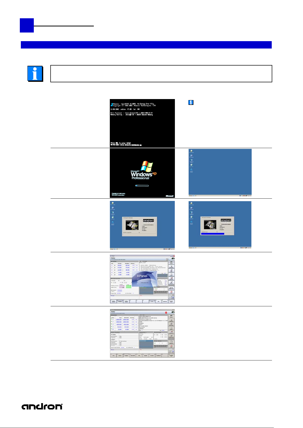
Switch on, start-up phase, turn off ......................................... 6
Switch on ....................................................................... 6
Boot phase ..................................................................... 6
Switch off / Shut down .................................................... 7
Operating system setting, system additions, user profiles, etc. . 8
Operating panel keys ............................................................ 9
The XPanel user interface .................................................... 12
Introduction .................................................................. 12
XPanel structure ............................................................ 12
XPanel pictograms of the status area.............................. 13
Revisions
3
Overview of the eight main groups ....................................... 14
The status display ............................................................... 16
The main menu of the status display .............................. 16
Zero points , Manage Zeropoint offsets ................................. 21
The main menu of the zero points .................................. 21
Tool management ............................................................... 23
Overview of functions .................................................... 23
The main menu of the tool management ........................ 23
Cycles ................................................................................. 30
The main menu of the cycles .......................................... 30
Programs ............................................................................ 33
The main menu "Programs" ........................................... 33
andron NC Editor .......................................................... 35
Service ............................................................................... 39
The Service main menu ................................................. 39
Error and Messages ............................................................. 45
The main menu Error and Messages (E/M) ...................... 45
Page 4
4
andronic CNC
XPanel Operating instructions
In the creation of this manual, w e have made the greates t effort and have taken the greatest care. We reserve the right
part of or the
Before the connection and the start-up of the control, it is imperative that
the documentation is carefully read!
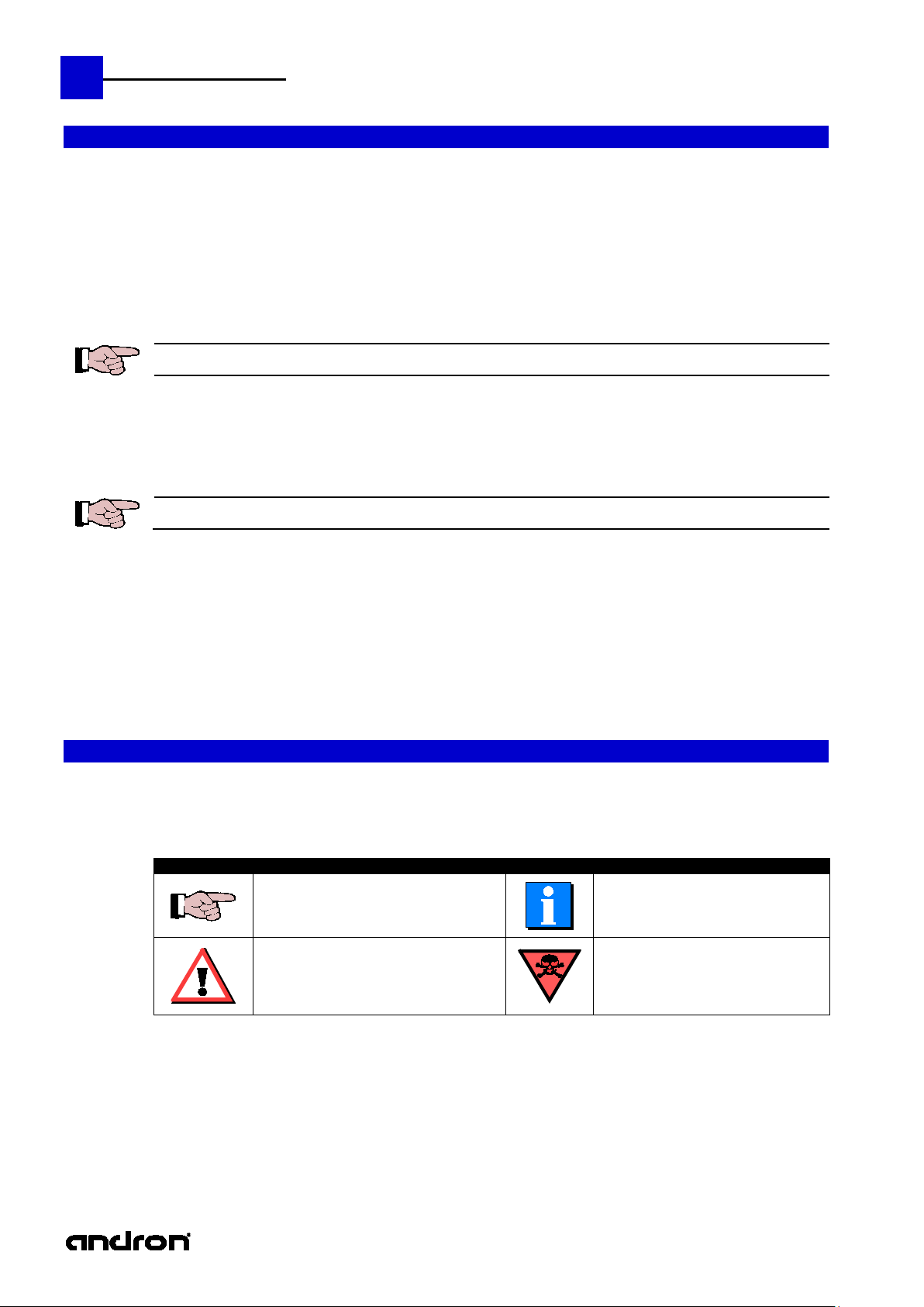
Meaning of the symbols used in this document:
Symbol
Meaning
Symbol
Meaning
Notice
to make changes to this manual a nd to the c ontr oller or the p rogra ms , whic h are made nec ess ary by technic al progre ss,
without previous notice. In later v ers ions, additio nal p ages ma y b e i nserted. We would appreciate your informa tion as to
errors in the manual or how the manual may be improved.
We accept no responsibility for damage resulting from neglect of the instructions contained in this manual.
We are neither liable for nor respo nsible for actual or alleged loss or damage , whether dir ect or indirect, which is caused
by the operated or delivered equipment or the software progra ms, and which are claimed by a customer or another
natural person or a legal entity. This clause includes fault y service, lost busin ess tr ansactions , loss of expec ted profi t or
consequential damages which occur due to the use of the equipment sold by us or software generated by us.
We accept absolutely no responsibility for damage due to faulty installation !
This instruction manual, the program descriptions belonging to it as well as other objects sold or supplied with the
controller, are protected by copyright. All rights ar e reserved. This handbook, the programs, and all other copyrighted
objects may be neither completely or par tially copied or in any other manner duplicated, without the previous written
consent of andron GmbH. Legally created copies, made with the permission of andron GmbH, of a
complete manual, the c omputer programs or other copyrighted objects, must have the same copy right notice as the
original material.
Safety notes
Warning notes and sym bols
This notice contains general and additional
information as well as rules and prohibitions
pertaining to damage prevention.
Danger notices for personnel and machine
damage, i.e. information as well as rules
and prohibitions pertaining to personal
injury and material damage prevention.
Important information or cross-
references to further descriptions.
Danger to life !!!
Page 5
andronic CNC
XPanel Operating instructions
Introduction
andron products are developed and produced according to the latest technologies . They are not delivered unless they
andron assumes no liability for damage due to inappropriate use. andron is not liable for payment of
The following requirements must be met before using andron products to ensure proper use:
Field of
The control is used for con trol panel integration, integration into a housing or the door of the switch c abinet or for
Each control system must be parameterized and programmed by competent service personnel before operation.
The control is "not used as directed" if it is used in a field of application not specified or if it is used under operating
Use as directed
have been tested for service reliability.
The products may only be used as directed. If they are no t used as directed, material damage and pe rs onnel inj ury may
result.
The corresponding safety instructions for use as directed must be read and understood by all who operate one of
our products.
If the products include hardware, the origi nal condition must not be changed . Software products must not be de -
compiled and the source codes must not be changed.
Damaged or faulty products must not be integrated or put into operation.
It must be guaranteed that the products have been installed according to the instructions specified in this manual.
damages. The user is liable at his own risk if the products are not used as directed.
5
applications
machine tool housing integration.
It must be ensured that the required mounting, installation and environmental conditions are fulfilled.
The control can only be used with the configurations described in this manual. Furthermore, the use of an andron
software or firmware is necessary.
Not used as directed
conditions or with technical data not spec ifie d in this manual.
The control must not be used if it is exposed to operating condition s which do not fulfill the determined environmental
conditions, e.g. use with water or with extreme temperature differences or extreme maximum temperatures is not
allowed.
Page 6
6
andronic CNC
XPanel Operating instructions
If the control was started without
Switch on, start-up phase, turn off
Switch on
Boot phase
1.
The switching on of the control as well as the entire system can be realized in different ways,
Switch on the control
Boot phase of the HMI CPU
therefore observe the information of the machine manufacturer!
connecting or switching on a display, it ma y
happen that the display remains dark after
switch-on.
In this case, press the key combination
CRTL + ALT + F1 (for VGA)
CRTL + ALT + F3 (for DVI)
in order to switch to the correct output of the
graphics card.
2.
3.
4.
Loading of the HMI
operating system
Boot phase of the NC CPU
Loading of the NC operating
Initialization of the
operating system
Start-up of the
sercos phases
from 0 to 4
system
5. Control is ready for operation
Page 7
andronic CNC
XPanel Operating instructions
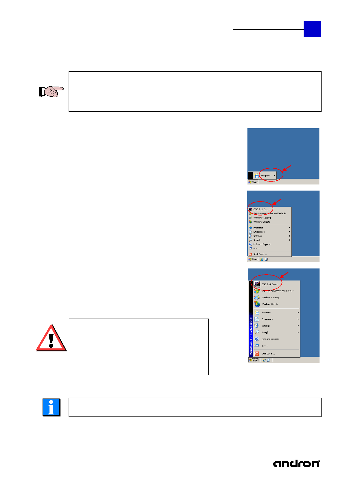
There are different possibilities to shut down the operating
Attention:
system is not monitored as to whether the machine is still
Switch off / Shut down
7
For switching off the control as well as the whole machine pay attention to the following notes:
To avoid data loss or hard disk damage the control must be shut down always in the correct way. That
means the operating system must be completely finished before switching off the control or the whole
system, depending on how you have logged in to the control:
Click in the Windows start menu on
CNC Shut Down
These actions will shut down the operating system, so that you
can surely switch off the power supply of the control..
machine.
cnc user
cnc admin
If you have logged in as User "administrator" or "cnc admin", you
can click on Shut Down in the Windows start menu. However,
your are strongly advised not to do so, because the
in the machining phase or other important functions are
still active!
Observe also the information of the machine manufacturer!
administrator
Page 8
8
andronic CNC
XPanel Operating instructions
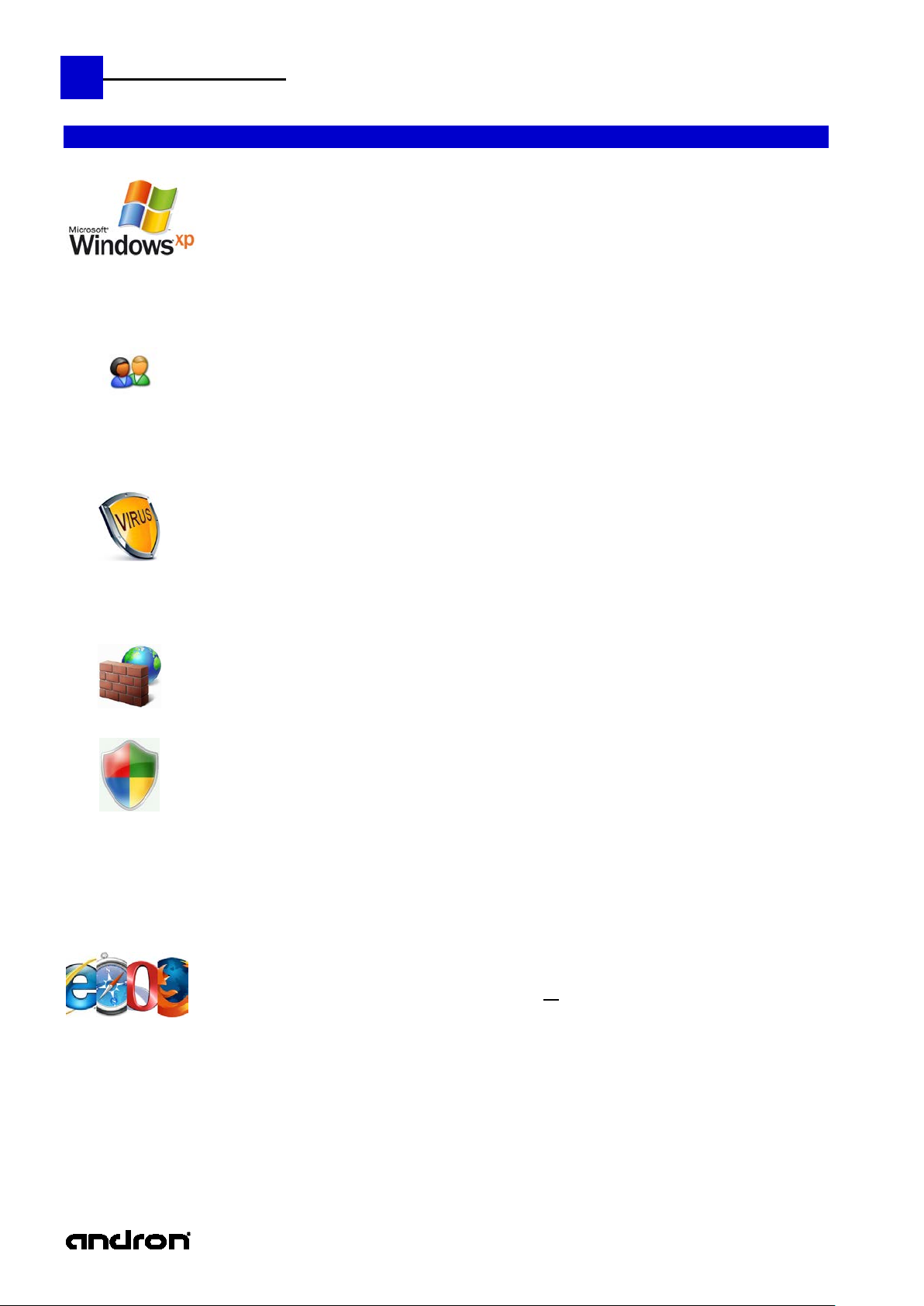
Microsoft Windows XP Professional (SP3) is the installed operating system on the HMI computer of the
additions and other optical gadgets are deactivated. Changes in these settings can slow down the system
User-Profiles
Virus scanner
Firewall
Microsoft Security Patches
security patch or other update without permission of
Internet access
Only with full access and
Operating system setting, system additions, user profiles, etc.
andronic 3060.
In order to guarantee the highes t poss ible sys tem performa nce , all unneces sary animat ion, s uperfluo us s oftware
considerably.
Three users with corresponding user profile were arranged on the control:
administrator (Full access with administrative rights)
cnc-admin (Reduced administrative rights)
cnc-user (Considerably reduced user rights for the machine user on operating system level)
Please use only one of the three predefined users.
We recommend the use of an actual virus scanner.
A complete virus scan is executed before the control is leaving our factory. T he installat ion of a dd itional s oftware
or the use of USB memory stic ks can cause a virus infection of the system. A final virus check mu st be done
before the entire machine is delivered to the end user.
In the default setting the Windows
The installed image contains most of the availa ble Microsoft
security patch in the current version, because after every installation extensive software-tests must occur in
order to guarantee the perfect function of the entire system
It is forbidden to install any Microsoft
ANDRON. It is also not allowed to activate the automatic update function in the Windows security
center.
When using the control with not verified software, the guarantee of the control will be lost.
In the standard configuration the machine user has no internet access.
administrative rights can you connect the control to the Internet
The andronic software offers the poss ibility o f remo te diagnos is via internet with the prog ram N etVie wer. To use
this function it is necessary to make a r estricti on on administrator level s o that the mach ine user has no general
internet access.
XP firewall is activated. The use of other firewalls is dissuaded urgently.
security patc hes. It is not possible to ins tall every
Page 9
andronic CNC
XPanel Operating instructions
below. It is possible that the machine manufacturer delivers his own PLC program with different functions
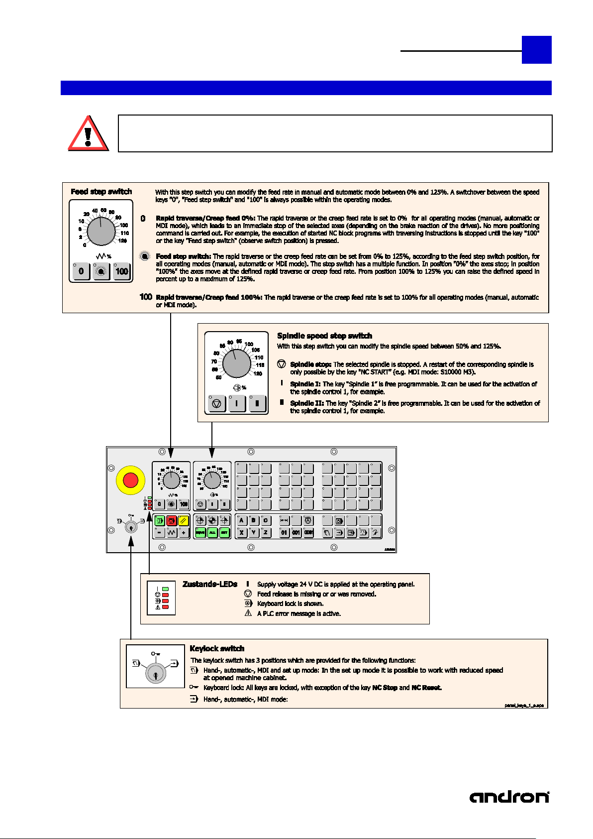
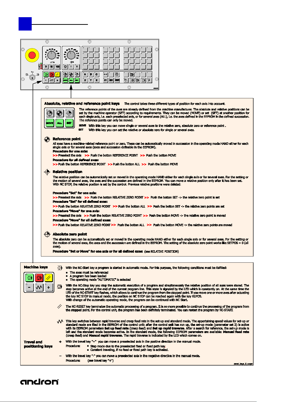
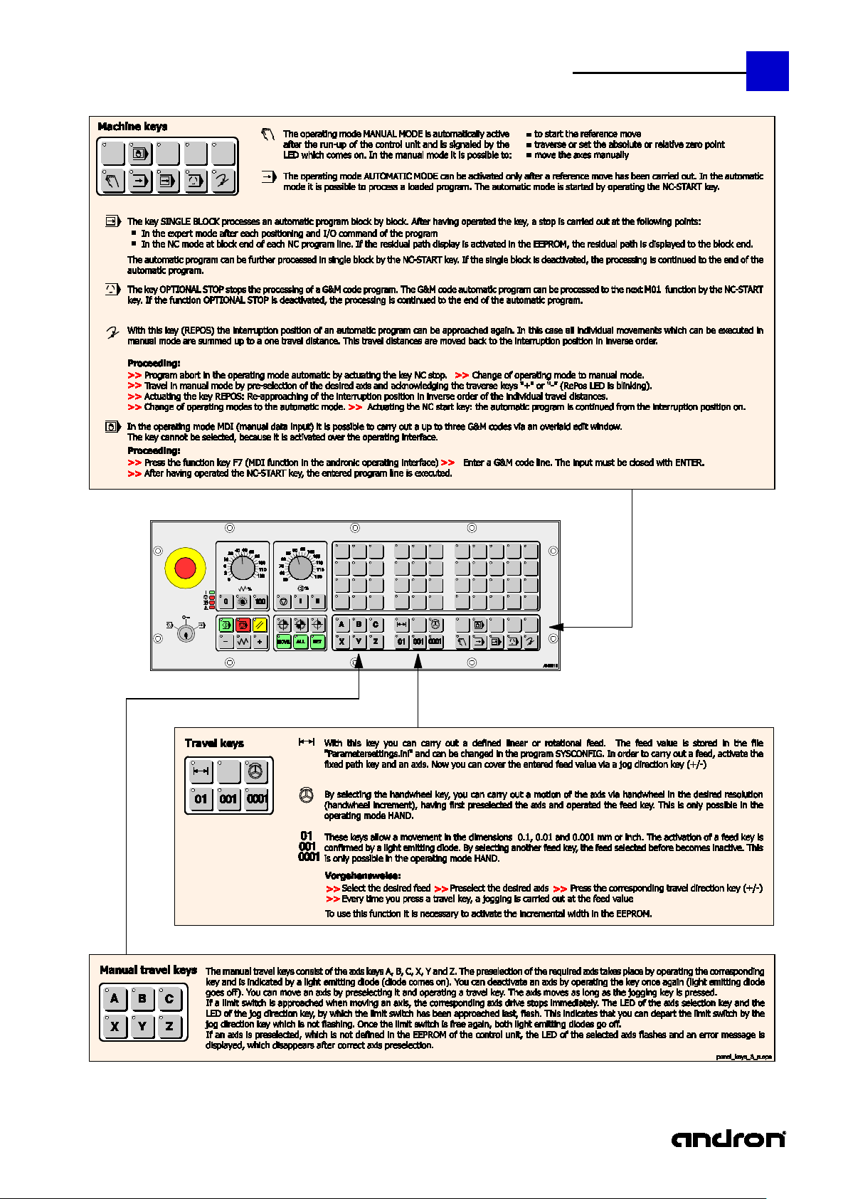
Operating panel keys
andron supports the control with a basic PLC program for the operating and control functions described
and extensions. If there is no further information the following description is valid.
9
Page 10
10
andronic CNC
XPanel Operating instructions
Page 11
andronic CNC
XPanel Operating instructions
11
Page 12
12
andronic CNC
XPanel Operating instructions
Introduction
The pleasantly designed and cle arly structured operating interface can be operated i ntuitively. The Micros oft
XPanel
Despite the extensive configuration options , the different areas of the interface are clearly defin ed. The outer
Status area
At the top, extending from left to right over the en tire screen, is the s tatus area in which on the
Main group
The right-hand side of the screen features eight MG keys.
They can be activated by pointer devices (mouse, touch, etc.) or the key combinations
Underneath are two
Function
At the bottom of the screen are the function keys F1 – F10. They are assigned according to main
To delete the
The attempt was made to place the same functions in all bars on the same function key. Context-dependent,
function keys become enabled or disabled.
The XPanel user interface
.NET based panel has various configuration possibilities and can be ad justed problem-free to the needs of the
end user.
Our andronic CNC controls has a w ide range of applications, ranging from classical machi ne applications like
milling, honing, grinding and eroding to highly dynamic processing. For this reason we put a lot of value during
the design of the new panel in individual adjustment options and optimal usability.
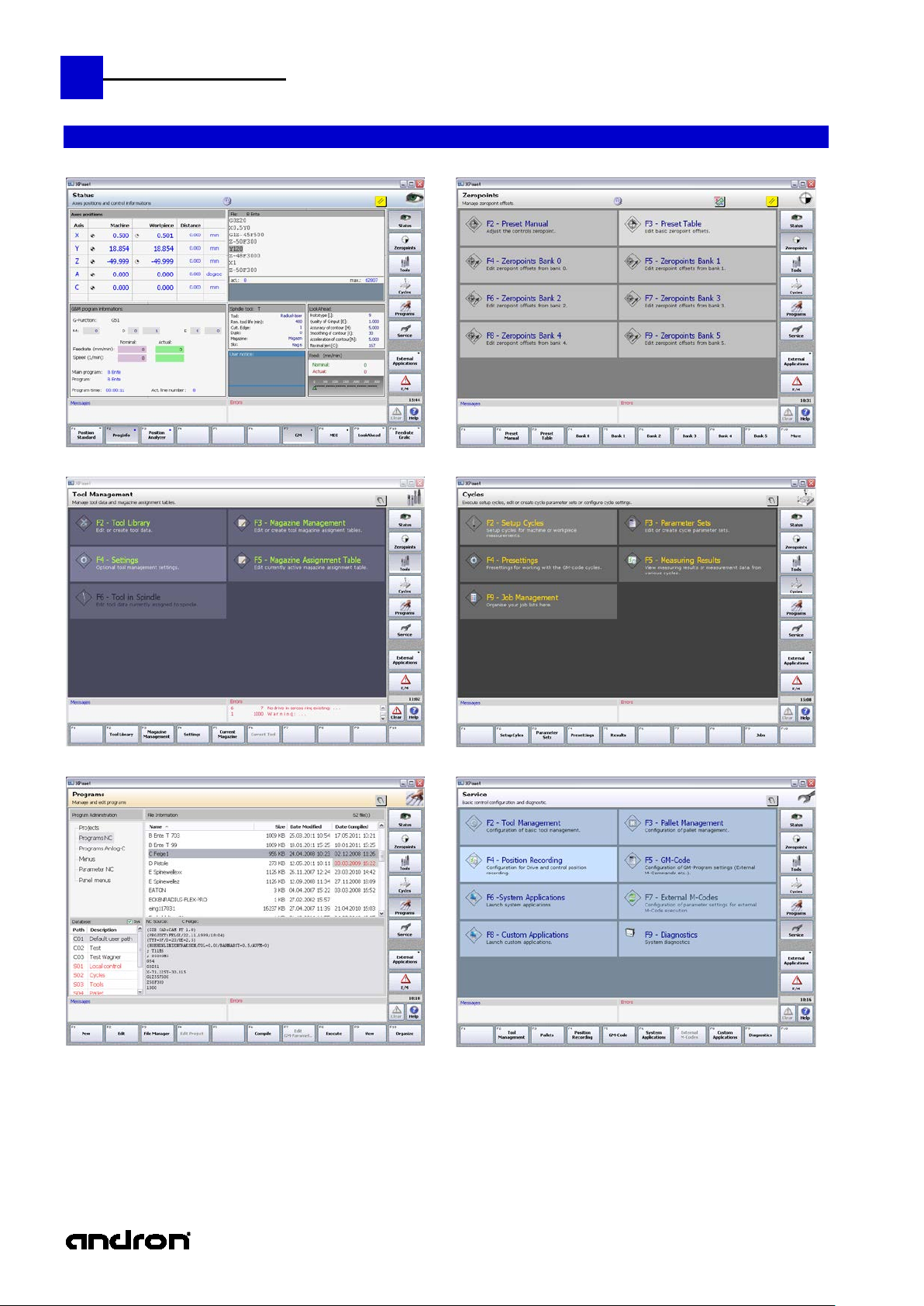
Illustration: Structure and functional areas of the XPanel interface
structure
frame of the XPanel always has the same appearance, allowing the user to become quickly familiar with it. The
basic information always appears at defined locations:
left the name of the active main group and underneath a description of the current action
appear. This is followed by pictograms r eproduc ing the status of th e re mote mode, key-operated
switch, active transformations and of the current CNC operating mode.
On the very right in the status area, the pic togram of the acti ve main g roup (MG) is shown. The
background color of the status area depends on the main group.
area
keys area
Ctrl+Shift+Alt+F1 – Ctrl+Shift+Alt+F8.
Main group 7 cam be configured. This is indicated by t he small inverted black triangle in the right
upper corner. I t is configured by clic king this triangle or by a right mouse click on this button.
From the popup menu that appears, a function can be assigned.
Note: If the function is active, no other function can be assigned.
Remedy: End the active function.
Below MG 8, the local time and the current date are shown as tooltip.
smaller buttons.
"Clear" deletes the accumulated errors within the applic ation. The key is only active if any errors
are active. The next time XPanel is started again, these errors will reappear.
"Help" (Ctrl+Shift+F1) provides context-dependent help.
groups and can be several levels deep.
Above them on the left is the area for disp laying messages (blue) and on the right the area for
error messages. Error messages can be deleted by pressing the "Clear" key.
messages, the message bits must be removed by the PLC or CNC.
Page 13
andronic CNC
XPanel Operating instructions
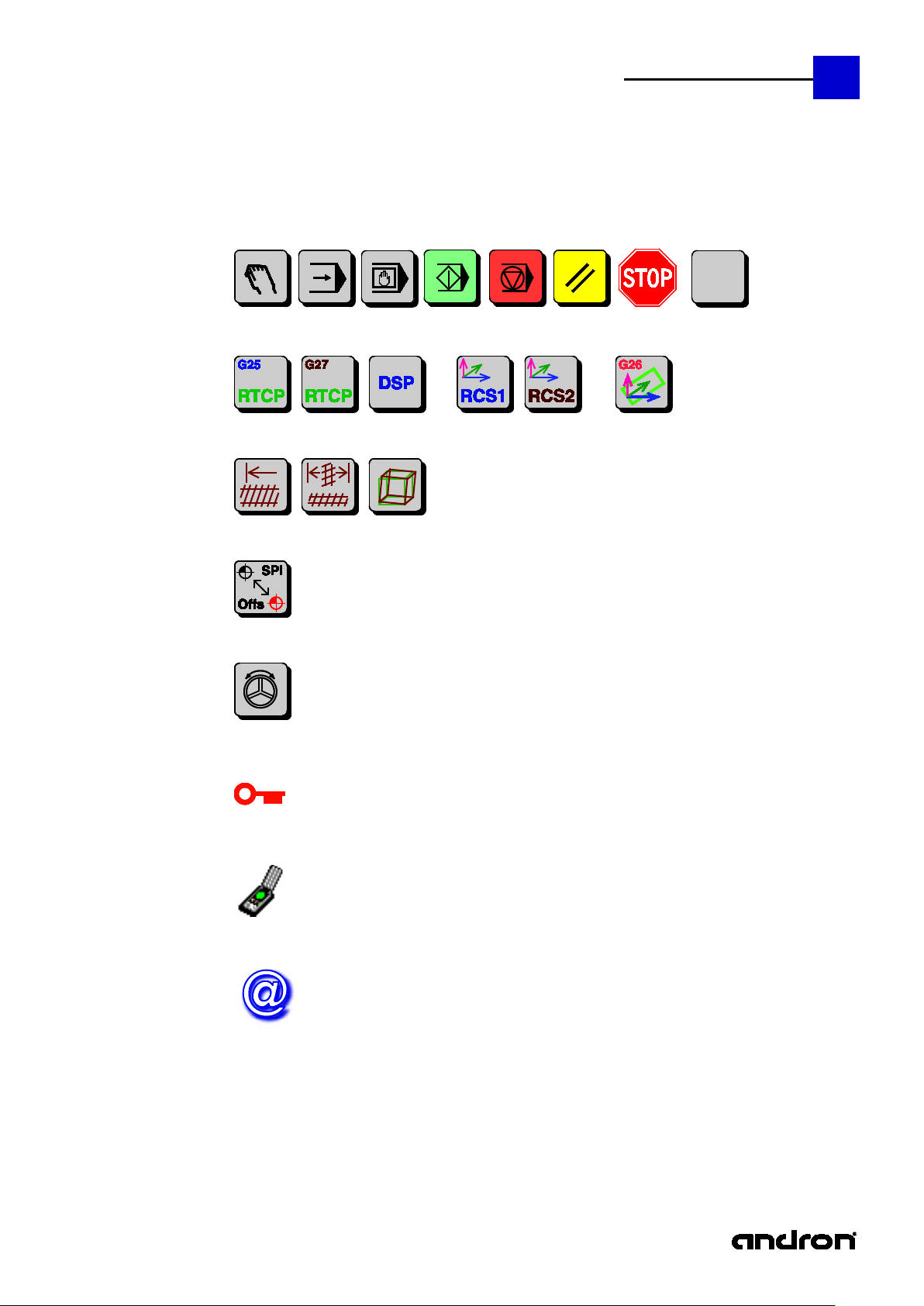
XPanel pictograms of the status area
Operating modes:
n in the event of an Emergency Stop, the empty pictogram is shown when the CNC could not
Transformations:
Compensations: (spindle, cross, grid)
Spindle Offset:
Handwheel Offset:
Control panel key-operated switch:
Remote mode:
Remote access:
13
Stop is show
initialized correctly. For the meaning of the remaining pictograms, see description of the control panel .
controls data input and remote mode
In NC block mode, the control is rem ote-controlled. Remote mode and remote access are mutually exclusive.
The control (programming station) access the data of a remote control. The toolti p provides the computer name.
Page 14
14
andronic CNC
XPanel Operating instructions
Overview of the eight main groups
Status
Tool Management
Zero points
Cycles
Programs
Service
Page 15
andronic CNC
XPanel Operating instructions
15
Configurable main menu
E/M (Error and Messages)
Page 16

16
andronic CNC
XPanel Operating instructions
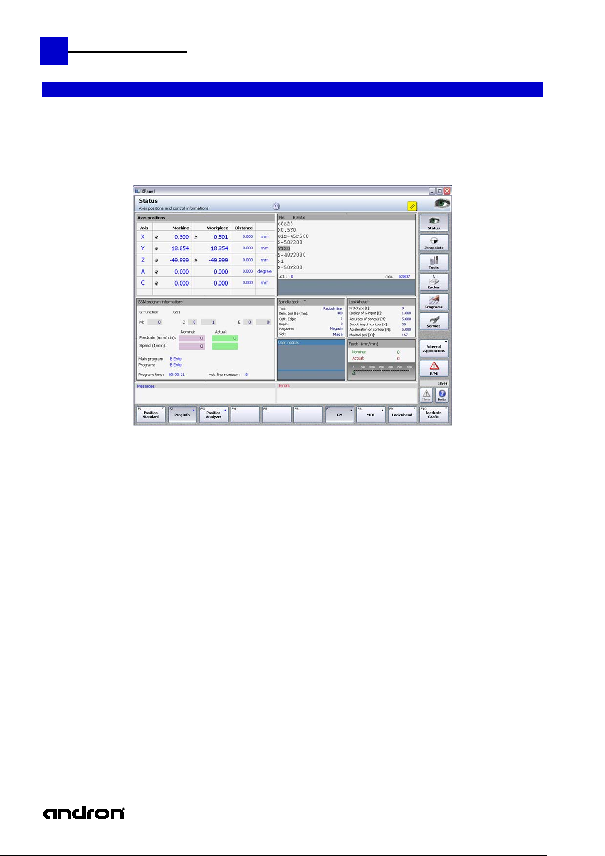
The main
The status display is divided into 16 fields of equal size. These fields can be configured for each language via the
Group affiliation of
To let the user know which function keys have toggle functional ity or which keys belong to the same group,
The status display
menu of the
XML file ...\andron\Panel\Plugins\State.Config.
status display
Illustration: Division of the status display into 4x4 fields of equal size
For these fields, controls (display and input windows) of different size (multiple of the basic field size) are
available. The user can change their arrangement, but not the controls themselves.
For the configuration of the fields, a separate description is available: StateConfig
the function keys
graphic elements are shown on the function keys.
A black triangle with the tip pointing downward is a toggle key. At least two controls are
incorporated in them. You can toggle between these controls by pressing the key repeatedly.
A square means that the key belongs to a group.
The same color means the same group. The controls of a group are always shown in the same area of
the status display.
Page 17

andronic CNC
XPanel Operating instructions
At present, the following controls are available.
StatePosit2x2
(Standard display)
A8Setter
(Setter display)
The reference status was color-
StateProgInfoGM
Visualization of the NC block program information
17
(2x2):
(2x2):
Metric display of a max. of 5 axes. The axis designator,
machine with reference status, workpiece with manual
preset offset, remaining path and dimension are displayed.
Which axes and in which order they are shown, can be
defined via the configuration file XPanel.exe.Config. By
default, the axes XYZAC are shown. The two figures in
parentheses behind the name of the control indicate its
size in field rows and columns for which the control was
designed.
In this illustration, all axes have been referenced, and the
Metric display of a max. of 8 axes. The axis designator with reference status and manual preset offset, Sercos,
drive, machine, work piece, remaining path and dimension are displayed.
For reasons of space, both the manual preset offset and the refe rence status are shown in the axis designator
column.
Z axis has been assigned a manual preset offset.
coded in the axis designator:
green referenced
red not referenced
(2x2):
Modal G functions, M-D-E words, federate, spindle speed (Nominal/Actual), start and current NC program,
previous program time and line number of current program.
Page 18

18
andronic CNC
XPanel Operating instructions
StateMDIAlpha
MDI Control:
MDI is enabled by pressing the f u nction ke y F8 MDI or by cl ic king i nto the tex t inpu t f ield. The background color
The status line above the four keys is used both for user guidance and for displaying compilation error
positioned in the faulty NC block line.
buffer. Execution can start.
(2x2):
Input of multi-line NC block instructions.
The length of the MDI source is limited by the
size of the transfer buffer.
of the text input field changes and becomes focus e d, while the status line and the CNC buffer are deleted.
MDI is disabled by pressing the "Disab le MDI" key or by c licking on a different c ontrol. The text input field turns
gray and loses the focus.
messages.
Key "Delete All" or Ctrl+A: Text input field is deleted, CNC buffer is empty.
Key "Alpha": another window containing predefined strings is displayed and becomes focused if it was
already visible. The strings in this window can be transferred to the text input field and the selected text
position via Drag & Drop, double-click or by press ing the Enter key. Upon transfer, the text input field
becomes focused, allowing you to continue writing immediately behind the inserted string. The text s trings
have been defined in the MDIKeys-config file and are not lang ua ge-specific.
The file is located in the directory: ...\andron\Panel\Plugins
Note: a string can only be transferred by pressing the Enter key if the string was selected and the Alpha
window is focused.
Key "Compile": The contents of the text input field is compiled, transferred to the CNC buffer, and a status
message is output. As the Enter key will also trigger compiling, Ctrl+Enter is used for the line feed.
Key "Disable MDI": MDI is disabled. If MDI is still being executed, it cannot be disabled.
MDI with Alpha keys window
In the event of faulty compilation, an error message is
output in the MDI status line, and the cursor is
The MDI status line signals that the MDI instruction
was compiled correctly and transferred to the CNC
Page 19

andronic CNC
XPanel Operating instructions
StateGMSrcView1
Display of the NC block currently to be
StateTool (1x1):
Display of the data relevant to the spindle
StateUser1 (1x1):
Display of user notes.
StateFeedGaug1
Explicit and graphic display of the
StateFeedSpindle
Display of nominal/actual values for federate
StateFeeds (1x1):
Editing of the fixed feed both for linear and
StatePLCTimer
Display of the first 4 PLC timers. They can be
StateLookAhead
Display of the currently used LookAhead data.
19
(2x2):
(1x1):
executed in the CNC, including the filename,
the current and maximum line number and a
max. of 3 single-line texts.
The texts are defined in the NC block via G2 3.
The NC block can only be displayed if it is not
more recent than the code executed in the
CNC.
tool.
A maximum of 2 multi-line texts are possible.
The display area for the texts can be moved
by means of a pointer device. (SplitWindow)
nominal/actual feedrate The green triangle
represents the nominal value, and the actual
value is shown as a red bar.
(1x1):
(1x1):
(1x1):
and speed.
rotary axes.
started, stopped and reset via the PLC.
Resolution: 1 sec
Page 20

20
andronic CNC
XPanel Operating instructions
StateVersionInfo
Display of the installed versions of the
StateGM (1x1):
Display of the MDE NC block parameters
StateGMSrcView
Display of the NC block currently to be
If this control is used in
StateUser (1x1):
Display of user-specific information, suc h as
StateFeed (1x1):
Display of the nominal/actual feed. The actual
StateFeedGaug
Here the same data as in StateFeed are
StateSercosSpindle
Display of the Sercos spindle "0". In addition
The torque value is
StateSpindle (1x1):
This control is used for displaying an analog
Controls not used at the present time
(2x2):
(1x1):
individual modules. In contrast to the control
version, not the entire information is available
for the demo versions.
and of the active G commands.
executed in the CNC, including filename,
current and maximum line number. The NC
block can only be displayed if it is not more
recent than the code executed in the CNC.
machine runtime, current fixed paths and
user information.
2x2 field or larger, the size
of the font will be
changed.
feed is also shown on a progress bar. The
upper range limit (here 3000) can be
configured jointly for all 3 controls in the XML
file Posit.Views.dll.config.
(1x1):
shown.
Instead of the progress bar, an analog display
instrument is used.
_0 (1x1):
to the nominal speed, the actual speed and
actual torque of the Sercos spindle "0" are
shown both explicitly and graphically by
means of a progress bar. The upper range
limit for the actual speed (here 40,000) can
be configured jointly for all 3 controls in the
XML file Posit.Views.dll.config.
spindle.
Except for the torque, the same da ta as in
StateSercoSpindle are visualized.
displayed in percent.
Negative values are shown
in both displays in the
color lavender blush.
Page 21

andronic CNC
XPanel Operating instructions
The main
F2
Preset Manual:
Zero points , Manage Zeropoint offsets
menu of the
zero points
21
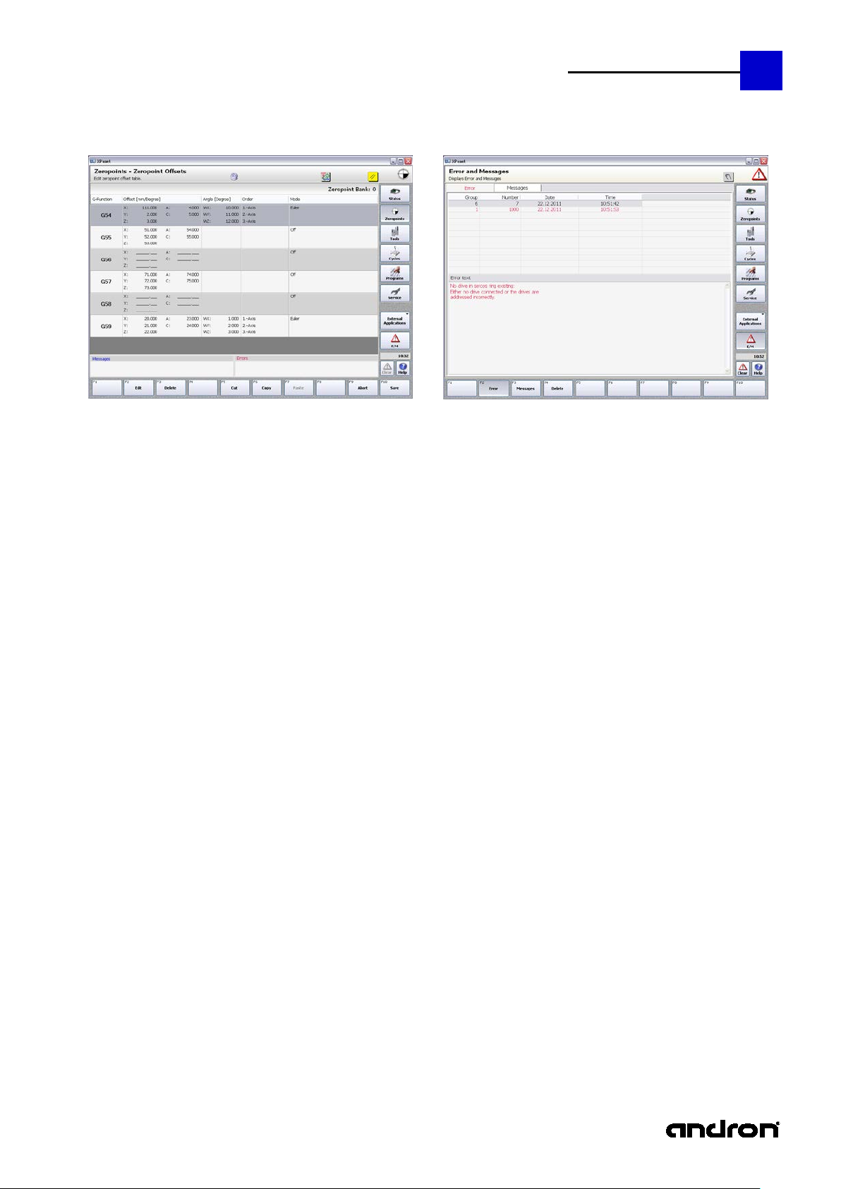
Illustration: The main menu of the zero points
Definition of the workpiece zero
point
This input screen can be used to offset
the workpiece zero point axisspecifically or to delete an offset again.
The correction value of a button can
also be included in the calculation. An
offset is shown axis-specifically in the
status display.
Page 22

22
andronic CNC
XPanel Operating instructions
F3
Preset Table:
F2: Edit selected preset group
F3: Delete a preset group
F4-
Zero point Offsets
Saved preset offset
In the same way as the zero point
offsets, a preset offset (G5 1) can also
be stored. In contrast to the zero
points, the preset table contains all 10
possible groups.
Preset offsets can be stored as the
result of measurement cycles or
entered directly by the user.
F10
F5-F7: Cut & Paste functions for a group
F9: Discard changes
F10: Save changes
Groups 0 to 99
The groups 0 - 5 are directly
addressable. All other groups are
selected by explicitly specifying the
group in an input dialog.
Each group contains the translatory and
rotatory offsets for the G functions
G54-G59. The parameter modification
of a zero point offset group is done in
the same way as that of a preset
group.
Page 23

andronic CNC
XPanel Operating instructions
Overview of
any number of tool maga zines
The main
Tool management
23
functions
menu of the
tool
management
100 tool magazine slots per tool magazine
clear overview of the magazine slots
tool status information in the magazine table
any number of tools per tool type
input forms tai lored to tool types
variable or fixed coding of slots
duplo tools
tool life control / wear control
3 different types of status indication
limitation of maximum speed
speed control
9 pairs of correction values
Tool-dependent measuring data input for the laser tool measurement system
Numerous adaptation possibilities at the machine:
chain or disk mag azine, pick-up, manual change in any combination up to a total of 100 locations,
correction of position for every single magazine location,
programming of the tool change procedures in G&M code format
Different options:
tool can be changed , despite tool life has expired ,
interruption of the NC program during speed reduction of the tool management,
in case of tool magaz ine problems, all tools can be changed manually without intervening within th e tool
management,
worn-out tools can be disabled by the breakage control, but NC program is not aborted when an error
occurs.
Illustration: The main menu of the tool management
Page 24

24
andronic CNC
XPanel Operating instructions
F2
Tool Management / Tool Library
After selecting the tool type, a ll to ols of this type will be s hown in an overview . As concise information,
Tool input form
The forms of the individual tool types all have the same
Geometry:
consideration for compilation.
The radius dimension limit will be checked when loading the tool. If the tool to be loaded is
As a result of the two-level tool type /
tool display, a tool can be quickly
created, edited, deleted, renamed and
duplicated. Moreover, all tool
magazines can be searched for the
selected tool.
Since the spindle tool must be often
modified, it has been placed on a
separate function key (F8).
status, length, radius and modification date a re available. Moreover, the name and T number of the
spindle tool are shown. An hourglass in the tool column identifies the spindle tool.
The Tool and Modification date columns can be sorted. The status display immediately show s whether
the tool can still be used or must be replaced.
The selected tool can be edited by pressing "Edit" function key, the Enter key or by double-click.
For each tool type, an input form tailored specifically to that type is available.
Note: There are situations in which the CNC does not allow a tool file to be edited. Conversely,
Example shank cutter:
Length, offset and correction are
Radius , offset and correction are
the program sequence is stopped when the magazine assignment table is edited by the
user.
structure. One page for the geometry definitions, one pag e
for the technology data and, dep ending on the compl exity o f
the tool, 1-2 measuring data pages.
added by the control and the
result will be set as active tool
length when changing the tool.
added by the control system and
the result will be taken into
outside the range limits (wear), the duplo tool will be loaded, if one has been defined and is valid.
If this tool does not meet the requirements either, mac hining will be aborted and an error
message output.
The tool size in slots defines the size in magazine slots (see magazine assignment)
Fixed slot de fines whether the is always managed on the same slot in the magazine. If the slot
coding is variable, the CNC will search a suitable magazine slot, depending on the tool size.
Page 25

andronic CNC
XPanel Operating instructions
Additional correction values: Apart from the length and the radius of the tool, it is possible to call
assignment table (ST column) will be set to red.
Technology:
Measuring Data 1:
Measuring Data 2:
25
up from the NC program the length and radius data for 8 further p airs of correction values. To
this end, the NC address "D" or "D0=" is used with the number of the desired pair of correction
values. When calling the tool, the first pair of correction values will automatically become active if
no other pair has been activated with D2 (or D0=2) to D9 (or D0=9).
Tool status: To be able to use a tool, all three check boxes must be checked. Tool breakage can
be changed by measurement (load cell or laser), while wear control is influenced by the tool life
and the radius dimension limit. If one check box is not c hecked, the status of the magazine
This page contains stored data on the
tool life, speeds and cooling.
If no speed has been defined in the NC
program, the nominal speed will be
used. If too high a speed has been
defined, the maximum speed will be
used.
Here the input parameters for
measuring the tool are defined.
Depending on the complexity of the
tool, further tool parameters are
defined.
see BLUM operating instructions
Page 26

26
andronic CNC
XPanel Operating instructions
F3
Magazine Management
F1 New: a new empty table is created.
F5
Magazine Assignment Table
If a slot contains faulty entries or if the tool has not been defined sufficiently, an exclamation mark will
1st column as in the current magazine assignment.
Magazine selection:
The control can manage any desired
number of magazine assignment tables.
Since these tables are stored as files,
only characters also allowed in the NT
file system (NTFS) can be used. The
name of magazine currently used in the
CNC is shown on the left-hand side of
the window. The right-hand list box
shows all assignment tables, the
current table being identified by an
hourglass.
F2 Edit: the selected table is opened and can be edited.
Instead of F2, it is also possible to use the Enter key or a double-click on the selected table.
F3 Delete: the selected table is deleted.
F4 Rename: the selected table is renamed.
F5 Duplicate: the selected table is copied
F8 Apply: the selected table becomes the current magazine assignment table
F10 Back: return to the previous level
Note: the current magazine assignment can be neither deleted nor renamed.
Per assignment, up to 100 slots a re
available, depending on the tool sizes.
They can be divided via the
configuration (see Service/Tool
Management) into magazine, pickup
and manual slots.
An entry in the magazine assignment
table consists of the T-number, the tool
type, the tool name, the tool status, the
tool size, the slot assignment and the
duplo T-number.
There are situations in which the CNC does not allow machining. Conversely, the program
sequence can be stopped when the magazine assignment table is edited by the user.
appear in the unnamed column (on the far left). The spindle tool is identified by an hourglass in the
Page 27

andronic CNC
XPanel Operating instructions
F2 Edit: edits the selected slot entry. Instead of F2, it is also possible to use the Enter key or a
27
double-click. The T-number may have a max. of 8 digits and only appear once in the assignment.
The tool type is selected from all available types via a list. The tool is also selected according to
tool type. If the tool, due to its size, does not fit in this slot, a message is output during the
selection. The next 3 columns are set automatically, i.e., the data from the selected tool file ar e
shown. ST is green if all three check boxes of tool status have bee n checked in the tool file. GR
indicates the size of the tool and BE the slot assignment. In the above illustration, slot three
contains the tool T2 of the shank cutter type. The tool name is "Shank cutter L120 R7". The tool
is ready for use has a size of 2 slot unit, which is why it requires half of its adjacent slots. The
duplo tool is T102.
F3 Delete: deletes a slot entry from the table. The spindle tool must not be deleted.
F4 Move: marks a slot entry in the table for moving. Pressing this key produces a red frame
around the selected slot. The entry can be moved using the UP/DOWN cursor. The moving cycle
is finished by pressing the Enter key. Moving by means of the pointer device (mouse, touch) is
also possible. The slot to be moved is selected with left mouse button and moved while holding
down mouse button. While it is being moved, the slot also has a red frame. The cycle is finished
by releasing the left mouse button.
F7 Edit Tool: the tool of the selected slot can be edited directly.
F8 Tool Library: the tool library is opened.
F9 Abort: editing is finished without applying the changes.
F10 Save: editing is finished, applying the changes.
Note: the tool names are unique and type-independent. For example, if there is a drill "abc",
there can be no shank cutter "abc".
There are situations in which the CNC does not allow machining. Conversely, the program
sequence can be stopped when the magazine assignment table is edited by the user.
Page 28

28
andronic CNC
XPanel Operating instructions
F4
Tool Management - Settings
If the tool management does not find a tool with remaining tool life, the execution of the G&M code
Optional tool management settings.
1. Tool with expired tool life is
inserted after inquiry, if no other
tool is available.
This option is intended to facilitate that
a tool is used longer than the entered
tool life.
program is cancelled.
If the tool management does not find a tool with remaining tool life, the G&M code program is only
interrupted. value is set as spindle speed during the tool change. This fact is indicated by a message.
The execution of the G&M code program can be continued with the first released tool without
remaining tool life. The NC program can be canceled with NC-Reset.
2. G&M code program is interrupted by the tool management in case of speed reduction
If a value for the maximum speed of the current tool is entered and the speed programmed in the
G&M code program is higher than the maximum speed the speed of the spindle is reduced
automatically.
The spindle speed is reduced to the maximum speed of the tool without interruption of the G&M
code program.
In case of a speed reduction the G&M code program is interrupted with a message to provide the
possibility to decide whether to cancel the program or to continue at reduced speed. A new NC start
continues the G&M code program at reduced speed.
3. Suppress tool change sequences. All tools are changed manually.
To guarantee the operating function of the machine in case of damage of the mechanics for the tool
change, all tool change sequences can be forced to manual change without need to change the
magazine configuration and the magazine assignment tab le .
Standard operation
All tool changes are executed as "Manual change".
4. Lock worn-out tools, but do not abort GM program with error (G383/G384).
Cycles G383 and G384 can be used to carry out a wear test of the l ength and rad ius. To do so, a wear
tolerance is specified. If the measured wear exceeds this wear limit, the tool will be locked by the
cycle, and an error code will be returned to the CNC.
The NC program will be finished with an error message if a cycle identifies the tool as "worn-out".
The NC pr ogram will be continued with a worn -out tool. The next tool change of this tool will loa d
the duplo tool, if available, or finish the NC program with an error message.
Page 29

andronic CNC
XPanel Operating instructions
RESET
RESET of the error state of the tool change has not been canceled in the defined state !!
Tool change has not been
29
The tool change is monitored internally by the control. If, due to a pow er cut or similar events, an
undefined state should occur during the tool change, the following tool change is blocked. I n this cas e,
a tool change leads to a program abort and the error message „
canceled in defined state !! Check tool management and reset error.“.
The machine operator must check the tool management, compare it with the ACTUAL state in the tool
magazine and in the spindle, and reset this error state. After this, a tool change is possible again.
Standard operation
Reset error.
Attention ! It is absolutely necessary to check the tool in the spindle and the tool in the
position menu!
Page 30

30
andronic CNC
XPanel Operating instructions
The main
Here it is possible to execute setup
F2
Setup Cycles
For all available setup cycles, input
Cycles
menu of the
cycles
Illustration: The main menu of the cycles
All setup cycles can be executed from
here, and the measurement results can
be saved. The setup cycles are divided
into groups:
Drilling operations
Shafts
Ligaments and grooves
Sides
Space points
Workpiece
Workpiece - Machining
cycles, edit the parameter sets cycle,
establish presettings, display
measuring data and organize job lists.
screens containing parameters for
determining the measurement results
are available.
There is one page each for the setup
parameters and for the measurement
results.
Further information on all setup cycles can
be found i n the
"G&M code programming instructions".
Page 31

andronic CNC
XPanel Operating instructions
F3
Cycles – Data S ets
Edit or create cycle parameter
Further information on the
instructions" or in the Help
F4
Cycles - Presettings
31
For all cycles, a max. of 1000 (0-999)
parameter sets can be created, edited
and saved. The cycles are divided into
five groups:
Drilling and milling cycles
Measuring cycles
Set-up cycles
Continuous operation axes
Blum cycles
sets:
Here data set 1 is given as an example
of the G81 drilling cycle.
individual cycles can be found
in the "G&M code programming
For some NC block cycles, special
presettings can be established and
saved.
Here is the main menu for the following
cycle groups:
Measuring plate (G187, G188,
G189)
Measuring probe (G181, G285)
Blum cycles (G381-G389)
General (G288 Look ahead
parameter
Page 32

32
andronic CNC
XPanel Operating instructions
F5
Cycles – Measuring Results
F9
Cycles – Job Management
View measuring results or measuring
data from various cycles.
Here is the main menu for the following
measuring results:
G789 – Timer
G789 – Time Stamp
G789 – Start Delay
G381 – Laser Calibration
G382 – Temp. Compensation
Here it is possible to define job lists
(000-999), which allow the following
functions:
to start more than one NC
program in a row,
to allocate a pallet number to
every program
to restart an NC program by the
PLC after being aborted by, e.g.
ERROR Exit.
The execution of the job list is
continued with the next released
NC program.
Further information on the
job lists can be found
in the Help "Ncsatz_Bedienung.chm".
A parameter description and further information on the
individual cycles can be found in the "G&M code programming instructions"
or in the Help
Page 33

andronic CNC
XPanel Operating instructions
The main
The program-specific screen is divided
Array
Program
Administration
(B1)
Projects
Programs
33
menu
"Programs"
Illustration: The main menu "Programs"
General: the lists in B1 and B2 can be sorted. The column in which
sorting takes place and whether it is done asce nding or descending
order, can be seen from the triangle in the column heading.
Here both NC block and Expert Mode projects can
be created. A new project is created by pressing
the function key F1. The project is edited by
pressing Edit Project (F4). In an Expert Mode
project, first the menu is selected, and then IDN
and the program are selected. Only those files
are displayed that fit the menu in terms of type.
Optionally, as with the NC block project, a
commentary can be included.
The existing NC block or Expert Mode project is
then displayed in the right upper window.
into four areas.
The two left-hand windows are always
the same, while the two right-hand
windows depend on program
management and the current database
path, which can be set in the left lower
section.
In the upper section (B1) Program
Administration, projects, NC block,
expert (anlog-C) programs and menu
filenames are shown.
In the lower section (B2), either ID
files of anlog-C programs or menus are
selected or NC blocks or project files
are displayed.
Sorting can take place both in B1 and
B2 according to column. Since are
designed as split screen, the display
ratio of B1 and B2 can be adjusted.
Page 34

34
andronic CNC
XPanel Operating instructions
An Expert Mode project is advantag eous when starting up a program. Once the project has been selected, the
F1
Creates a new project
F2
Edits the project NC block or the proj ect ID file (depends on the project type)
F3
File Manager: Import/Export of database files
F4
Edits the project
F5
Edits the PRKON file of the project NC block (option in xpanel.exe.config)
F6
Compiles the project NC block
F7
Edits the NC parameters if the project NC block is parameterizable
F8
Compiles the project NC block, if necessary, and transfers it to the CNC or, in the case of an Expert
Mode project, loads IDN and program to the CNC.
F9
Visualization of the NC block by means of 3Division Basic (requires activation in dongle)
F10
Behind organization, a new function bar is hidden. It allows NC block projects and IDN s to be r enamed
Note
When renaming an NC block or an IDN, the project files are not renamed automatically.
ID file can be modified by means of the menu by pressing F2 and then transferred to the CNC togeth er with the
relevant program by pressing F4. In the absence of a projec t, in order to edit the IDN, first the item M enu would
have to be selected in Program A d ministration , t hen the menu and IDN would have to b e selected a n d then IDN
modified. To load the program and IDN , the item anlog-C programs and then the program and IDN w ould have
to be selected.
and also to be deleted. When deleting, a multiple selection is possible as with the Explorer. Upon
pressing F3, the file manager can be started and, upon pressing F9, the database directory can be
changed.
Page 35

andronic CNC
XPanel Operating instructions
Array
Program
Administration
(B1)
NC Programs
F1
New:
F2
Edit:
andron
The andron NC Editor is an optimal tool
F3
File Manager: makes Import/Export of database files easy for the user
F5
Edits the PRKON file of the NC block (option in xpanel. e xe.config)
F6
Compiles an NC block
F7
Edits the NC parameters within a project if the NC block is parameterizable
F8
Compiles an NC block, if necessary, and transfers it to the CNC.
be compiled always or only if it was modified. Default: false.
35
Here new NC blocks can be created, modified,
visualized, compiled and transferred to the CNC.
Creates a new NC block
Edits an existing
NC block using a convenient
NC editor
NC Editor
for editing NC block files of any size. It
contains a configurable NC syntax with
tooltips and integrated help. An NC
wizard and the option of data transfer
from the clipboard complete the software
package.
Note: By entering "CompileAlways" in the X Panel.exe-Config, you can control whether the NC block is to
Page 36

36
andronic CNC
XPanel Operating instructions
F9
Visualization of the NC block by means
F10
Behind organization, a new function bar is hidden. It allows NC blocks to be renamed and also to be
In B1, the existing NC blocks are visualized. If an entry is missing in the "Compiled on" column, the program was
of 3Division Basic
(requires activation in dongle)
deleted. When deleting, a multiple selection is possible as with the Explorer. Upon pressing F3, the file
manager can be started and, upon pressing F9, the database directory can be changed.
not yet compiled. If the entry is shown in red, the NC block source was modified after compiling.
In B2, the first lines of the selected NC block are shown.
If in B1 an NC block was selected that is parameterizable, th is is shown clearly in the Program Administration
area. If a parameter set already exists for this NC block, the item "NC block parameter" is shown in green,
otherwise in red.
Page 37

andronic CNC
XPanel Operating instructions
Array
Program
Administration
(B1)
anlog-C Programs
Array
Program
Administration
(B1)
Menus
F1
Creates a new IDN. The name offered for the IDN is the menu name. If this name already exists, the
F2
Edits an NC block or an ID file (depends on the project type)
F3
File Manager: makes Import/Export of database files easy for the user
F10
Behind organization, a new function bar is hidden. It allows the ID files that match the selected menu to
Note: F2 is only enabled if an IDN was selected and is focused.
37
Here program and IDN are selected and
transferred to the CNC for execution.
F8 Transfers program and IDN to the CNC
F10 Behind organization, a new function bar
is hidden. It allows the ID files that
match the selected program to be
renamed or deleted. Upon pressing F3,
the file manager can be started and,
upon pressing F9, the database
directory can be changed.
Here new ID files can be created or existing ones
edited. Depending on the selected menu, only
those IDNs can be selected that fit this menu.
name is formed from the menu name + index.
be renamed or deleted. Upon pressing F3, the file manager can be started and, upon pr e ssing F9, the
database directory can be changed.
Page 38

38
andronic CNC
XPanel Operating instructions
Array
Database (B2)
In the Database area, the existing valid
Sometimes, the reaction times may be quite long. This is caused by analysis of physical directories that are not
in the
Should the text in the Description
Database paths can be created and changed via the system configuration (in
databases are displayed.
If the user has administrator rights, the system
database paths are also displayed. By default,
they are shown in red. The color can be changed
by making a "SystemPathColor" entry in
XPanel.exe.Config.
If the user has administrator rights, but does not
want the system paths to be listed, he can
show/hide them via the "Sys" check box at the
top right in the database area. This setting
remains valid after switching off the control.
Moreover, all database paths are updated by
pressing the Sys key. This is why the key is also
valid if the user has no administrator rights.
present.
Database
The
Organization
The Path column contains the short name for the database path.
Cxx (custom) stands for a user database path, xx indicating the path number.
Sxx (system) stands for the system database path, xx indicating the path number.
The Path column also shows the respective database directory as tooltip.
column be too long, the complete description can also be shown as a tooltip.
Note:
area can be activated either via a pointer device or by pressing F9
toolbar. The data area cannot be activated by pressing the Tab key, but it can be left.
Service\Systemprogramme).
Change Directory
Page 39

andronic CNC
XPanel Operating instructions
The Service
Here the basic configuration of the
F2
Tool Management
Tool Charger
Service
39
main menu
Illustration: The Service main menu
Configure tool charger and tool
magazine settings.
Magazine and change sequence
control and of the drives is
established.
Changes to the control and drive
configuration may only be made
by trained skilled personnel!
Note: If the user has no administrator
rights, he cannot used the functions
F2 - F6 (possibly F7).
Further i nformation can be found in the Help "Ncsatz_Konfiguration.chm".
Page 40

40
andronic CNC
XPanel Operating instructions
F3
Pallet Management
F4
Position Recording
Configure pallet management
Further information can be found in the Help "Ncsatz_Konfiguration.chm".
Record drive or control positions.
Page 41

andronic CNC
XPanel Operating instructions
F5
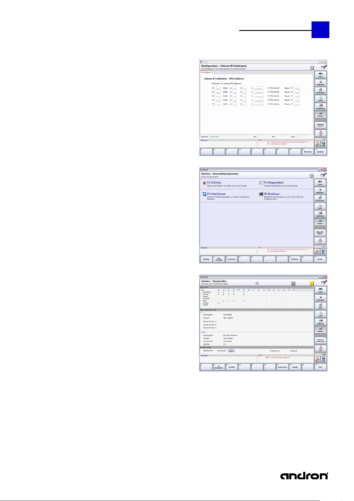
Configuration – GM-Code
The pages External M functions and
41
GM-Program settings (approaching
moves, external M-Commands, Block
Scan, special system events, offsets,
options)
Options describe the functionality of the
HMI in the main groups Cycles and
Service.
Changes will not become effective until
the XPanel is restarted.
Further i nformation can be found in the Help "Ncsatz_Konfiguration.chm".
Page 42

42
andronic CNC
XPanel Operating instructions
F6
System Applications
The system programs are used for
configuring the control and the
machine. The control should always be
shut down by pressing F8 ShutDown,
because this function first checks
whether a program is still being
executed on the machine. If this is the
case, the actual shutdown is prevented.
F1-Control Data:
Editing control parameters (EEPROM)
F2-Drive Data
Editing drive parameters (SERCOS)
F3-andron File Manager
Handling database
F4-System Configuration
Configuring of system components
F5-Position Analyser
Online position analysis
F6-DisLogData
Displays NC-Server logfile
F7-Virtual Machine
Virtual machine view
F8-ShutDown
Control Shutdown, if no program is
running at the CNC.
F9-Autologon
Configuration for automatic user login.
The general rule is:
Changes to the control and drive configuration may only be
made by trained skilled personnel!
Page 43
andronic CNC
XPanel Operating instructions
F7
External M-Functions
F8
Service – User programs
F9
Diagnostics
The start page provides information on
Program time is the time of the NC block to be executed.
43
Note:
If there are no external M functions (no
DLL installed), the function will be
shown in the overview, but it cannot be
selected.
Apart from the page of system
programs, there is also a page on which
user-specific programs can be stored.
By default, 4 programs are installed.
However, additional applications can be
added via a configuration file.
Diagnostics is designed not only to
provide the user with information on
the control and the machine, but also
assist him with problems.
This may include axis status, I/O
assignments, program and version
information and dongle data. Under
System Data, the user can view the
assignment CMOS, manual, PLC and
FastPLC parameters. As it is impossible
to visualize all parameters at the same
time, due to their large number, the
user has the option of displaying the
areas of interest.
Axes status:
Existing axes, axis designator, type and reference status. Red denotes not referenced, green
denotes referenced. The axis type - linear, rotating, modulo - is signaled by a check mark.
Files transfered to CNC:
This lists loaded programs, NC blocks and IDNs. In the execution of cycles, the information of the
Expert Mode can also be of assistance.
Runtime meters:
Machine time is the time during which the control was switched on.
Page 44

44
andronic CNC
XPanel Operating instructions
F2
I/O assignment
F3
VersInfo
F7
System data
F8
Dongle
provides all the information on the
signals of the 37-pin Sub-D socket, on
the InterBus-S, the NCIO card and NCM
X1X port.
provides the version information of
individual control components, but also
on another page an overview of the
previous product versions (History).
provides system data. They include
CMOS-RAM, manual, PLC and FastPLC
data. The areas to be displayed can be
defined by means of start and stop
indices.
View dongle information
Page 45

andronic CNC
XPanel Operating instructions
Errors and messages that have occurred during operation are visible in the compre ssed Error/Message display
The main
F2
Errors
F3
Messages
Error and Messages
45
menu Error
and Messages
(E/M)
under the main window. In contrast, in the E/M main menu, an entire page each is available for displaying error
and message texts.
Illustration: Compressed Error/Message display
The error messages can be reset by using the
CLEAR function.
Here errors and messages of the
control and of the machine are
displayed for the operator.
Errors are always shown in RED and
messages in BLUE.
Illustration: The main menu E/M (Errors and me ssages)
To switch between errors and
messages, press the function keys F2
and F3 or click on the tab at the top of
the window.
In contrast to error messages, message
texts cannot be deleted by the user!
This must be handled by the CNC or
PLC.
Page 46

46
andronic CNC
XPanel Operating instructions
Page 47

andronic CNC
XPanel Operating instructions
47
Page 48

48
andronic CNC
XPanel Operating instructions
 Loading...