

Page 1
2060
Introduction
1
Basics and overviews
2
Connection requirements
3
Operating panels
4
HMI/NC CPU card
5
NC multifunction card
6
TECHNICAL
HANDBOOK
andron GmbH
Schlätterstrasse 2
D-88142 Wasserburg / Bodensee
Phone:
Fax:
info@andron.de www.andron.de
+49 (0) 8382/9855-0
+49 (0) 8382/9855-50
Fieldbus interface card
7
8
9
PLC interface signals
10
Error messages
11
SPE / WPROM
12
Soft PLC / CoDeSys
13
Bootphase / BIOS codes
14
15
Page 2

Introduction
Page 3

Introduction
2
Technical Handbook
Editing/Illustrations Pasternak
Version V 1.1
Date 16.01.2007
Author Pasternak
Tools This documentation was created with Microsoft Word 2000 and Adobe Illustrator.
Trade mark All product names or trademarks are properties of their respective owners.
Copyright © andron GmbH 2007. All rights reserved.
Published by andron GmbH, Schlätterstr. 2, D-88142 Wasserburg/Bodensee
Copying this document, giving it to others and the use or communication of the contents thereof without express
authority, are forbidden. Offenders are liable for the payment of damages. All rights are reserved in the event of the
grant of a patent or the registration of a utility mode l or design.
Validity There could be additional functions running in the control who are not mentioned in this documentation. It insists no
claim for this functions, in case of a new delivery or a service case.
All rights are reserved with respect to the content of this documentation and the availability to the product.
Telephone +49 (0) 8382/9855-0, Fax +49 (0) 8382/9855-50
e-Mail:
info@andron.de
www.andron.de
01_introduction.doc
Page 4

Table of contents
Revisions........................................................................................................................................................ 4
General hints..................................................................................................................................................5
Safety notes...................................................................................................................................................6
Warning notes and symbols .....................................................................................................................6
Use as directed ....................................................................................................................................... 7
Introduction..................................................................................................................................... 7
Field of applications..........................................................................................................................7
Not used as directed................................................................................................................................7
Introduction
Technical Handbook
3
01_introduction.doc
Page 5

Introduction
4
Technical Handbook
Revisions
Version Date Additions and changes Initials
V 1.0 07.07.2003 First edition Pa
V 1.1 16.01.2007 Layout change to DIN A4 Su
01_introduction.doc
Page 6
General hints
In the creation of this handbook, we have made the greatest effort and have taken the
Introduction
Technical Handbook
greatest care. We reserve the right to make changes to this handbook and to the
controller or the programs, which are made necessary by technical progress, without
previous notice. In later versions, additional pages may be inserted. We would appreciate
your information as to errors in the handbook or how the handbook may be improved.
We accept no responsibility for damage resulting from neglect of the instructions
contained in this handbook.
We are neither liable for nor responsible for actual or alleged loss or damage, whether
direct or indirect, which is caused by the operated or delivered equipment or the software
programs, and which are claimed by a customer or another natural person or a legal
entity. This clause includes faulty service, lost business transactions, loss of expected
profit or consequential damages which occur due to the use of the equipment sold by us
or software generated by us.
We accept absolutely no responsibility for damage
This technical handbook, the programme descriptions belonging to it as well as other
objects sold or supplied with the controller, are protected by copyright. All rights are
reserved. This handbook, the programmes, and all other copyrighted objects may be
neither completely nor partially copied or in any other manner duplicated, without the
previous written consent of andron GmbH. Legally created copies, made with the
permission of andron GmbH, of a part of or the complete handbook, the computer
programmes or other copyrighted objects, must have the same copyright notice as the
original material.
Before connecting and starting up the control, the following documentation
due to faulty installation !
must absolutely be read!
5
01_introduction.doc
Page 7
Introduction
6
Technical Handbook
Safety notes
Warning notes and symbols
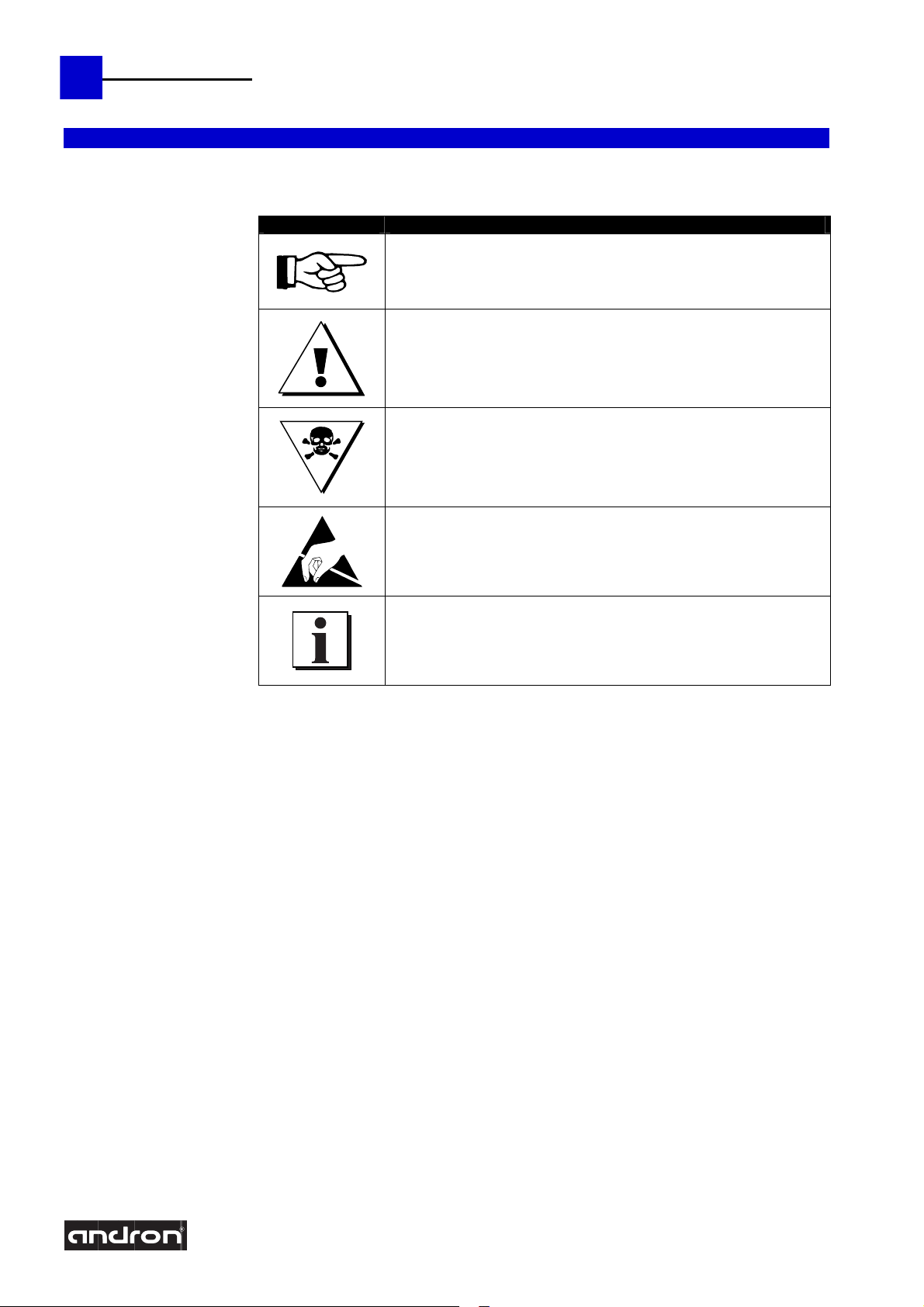
Meaning of the symbols used in this document:
Symbol Meaning
This notice contains general and additional information as well as
rules and prohibitions pertaining to damage prevention.
Danger notices for personnel and machine damage, i.e. information
as well as rules and prohibitions pertaining to personal injury and
material damage prevention.
Danger to life !!!
Danger of electrostatic discharge.
Important information or cross-references to further descriptions.
01_introduction.doc
Page 8
Use as directed
Introduction andron products are developed and produced according to the latest technologies. They
are not delivered unless they have been tested for service reliability.
The products may only be used as directed. If they are not used as directed, material
damage and personnel injury may result.
andron assumes no liability for damages due to inappropriate use. andron is not liable for
The following requirements must be met before using andron products to ensure proper
Field of applications The control is used for control panel integration, integration into housing or the door of
Not used as directed
The control is „not used as directed“ if it is used in a field of application not specified or if
payment of damages. The user is liable at his own risk if the products are not used as
directed.
use.
The corresponding safety instructions for use as directed must be read and
understood by all who operate one of our products.
If the products include hardware, the original condition must not be changed.
Software products must not be de-compiled and the source codes must not be
changed.
Damaged or faulty products must not be integrated or put into operation.
It must be guaranteed that the products have been installed according to the
instructions specified in this manual.
the switch cabinet or for machine tool housing integration.
It must be ensured that required mounting, installation and environment conditions are
fulfilled.
The control can only be used with the configurations described in this manual.
Furthermore, the use of a andron software or firmware is necessary.
Each control system must be parameterized an programmed by competent service
personnel before operation.
it is used under operating conditions or with technical data not specified in this manual.
The control must not be used if it is exposed to operating conditions which do not fulfill
the determined environmental conditions, e.g. use with water or with extreme
temperature differences or extreme maximum temperatures is not allowed.
Introduction
Technical Handbook
7
01_introduction.doc
Page 9
Basics and overviews
Page 10

Basics and overviews
2
Technical Handbook andronic 2060
Version V 1.6
Date 24.02.2010
Author Pa.
Editing/Illustrations Pa.
Tools This documentation was created with Microsoft Word 2000 and Adobe Illustrator.
Trade mark All product names or trademarks are properties of their respective owners.
Copyright © andron GmbH 2010. All rights reserved.
Validity There could be additional functions running in the control who are not mentioned in this documentation. It insists no
Published by andron GmbH, Schlätterstr. 2, D-88142 Wasserburg/Bodensee
Copying this document, giving it to others and the use or communication of the contents thereof without express
authority, are forbidden. Offenders are liable for the payment of damages. All rights are reserved in the event of the
grant of a patent or the registration of a utility mode l or design.
claim for this functions, in case of a new delivery or a service case.
All rights are reserved with respect to the content of this documentation and the availability to the product.
Telephone +49 (0) 8382/9855-0, Fax +49 (0) 8382/9855-50
e-Mail: info@andron.de
www.andron.de
02_basics_and_overviews.doc
Page 11

Table of contents
Table of contents............................................................................................................................................3
Revisions........................................................................................................................................................ 4
Hardware description......................................................................................................................................5
HMI computer.........................................................................................................................................5
NC computer...........................................................................................................................................5
Operating panels.....................................................................................................................................6
Connector and interface summary ................................................................................................................... 7
Survey of hardware components...................................................................................................................... 8
andronic 2060S ....................................................................................................................................... 8
andronic 2060L .......................................................................................................................................9
Survey of the operating panel connections ..................................................................................................... 10
Block diagram............................................................................................................................................... 11
Overview of the units.................................................................................................................................... 12
Front view of the andronic 2060S........................................................................................................... 12
Front view of the andronic 2060L ........................................................................................................... 13
Computer dimensions ................................................................................................................................... 14
Operating panel dimensions .......................................................................................................................... 15
Technical data.............................................................................................................................................. 16
Basics and overviews
Technical Handbook andronic 2060
3
02_basics_and_overviews.doc
Page 12
Basics and overviews
4
Technical Handbook andronic 2060
Revisions
Version Date Additions and changes Initials
V 1.0 03.07.2003 First Edition Pa
V 1.1 24.07.2003
V 1.2 26.08.2003 Additions: Profibus DP version Pa
V 1.3 18.03.2004 Additions: NCIO card with 37-pin I/O connector Pa
V 1.4 09.12.2005 Additions: Connector X80, X81 Pa
V 1.5 17.01.2007
V 1.6 24.02.2010
Change of CPU processor: Celeron CPU now with 1.2 GHz instead of 733 MHz
Change of harddisk: Fujitsu 2.5“ HD now with 40 GB instead of 20 GB
Layout change to DIN A4; New connector assignment X17, X19 and X60;
New HMI-CPU for andronic 2060L
Additions: Connector and interface summary (X2, X13, X19.5, X27, X42)
Update: Technical data (CPUs, HD, ...)
Pa
Su
Pa
02_basics_and_overviews.doc
Page 13

Hardware description
The andronic 2060 is a compact multiprocessor CNC system with HMI and NC computer
Basics and overviews
Technical Handbook andronic 2060
and an integrated Soft-PLC in one housings. Both computer systems communicate
together via fast PCI to PCI Bridge that is integrated on the common bus back plane. The
data transfer compared with previous systems rose up about the factor 50 and allows an
essentially faster communication between both computers.
The control is available in two versions. The extrem compact control andronic 2060S,
which is about 60 % smaller than the predecessor unit without any performance loss. The
bit bigger control andronic 2060L surpasses all previous standards in performance.
5
HMI computer
NC computer The NC computer contains a Celeron® plug-in CPU and a NC multifunction board (NCM) as
The HMI computer contains a Intel
with integrated Ethernet-, VGA- and IDE-Controller. The InterBus-S or Profibus-DP board
enables the connection to the operating panel and further I/O units. Beside the internal
hard disk, several USB interfaces for the connection of external devices like CD/DVD-ROM
or CD writer are available. For special applications further PCI boards can be configured
optionally in the andronic 2060L.
communication processor between the drive units and the control with all necessary
connections.
Besides the fast I/O interface and the four handwheel connectors, the NCM board has up
to four SERCOS interfaces available.
®
Celeron® M, Pentium® M or a Celeron® plug-in CPU
02_basics_and_overviews.doc
Page 14

Basics and overviews
6
Technical Handbook andronic 2060
Operating panels
Display operating panel
ANV03
XGA 15“ TFT display
Connection via standard VGA interface
Touch screen with USB interface
Standard dimensions 19“ x 7HE
Customer designs of inquiry
Machine operating panel
ANM013
Connected with control via InterBus-S or Profibus
Connection for further InterBus-S modules
Override switches for spindle and feedrate
EMERGENCY STOP button
Key switch for automatic and set-up mode with locking function
All keys with light-emitting diode confirmation
44 free assignable machine function keys
Connection of additional 16 input/ 16 output
Standard dimensions 19“ x 4HE
02_basics_and_overviews.doc
Page 15

Basics and overviews
Technical Handbook andronic 2060
7
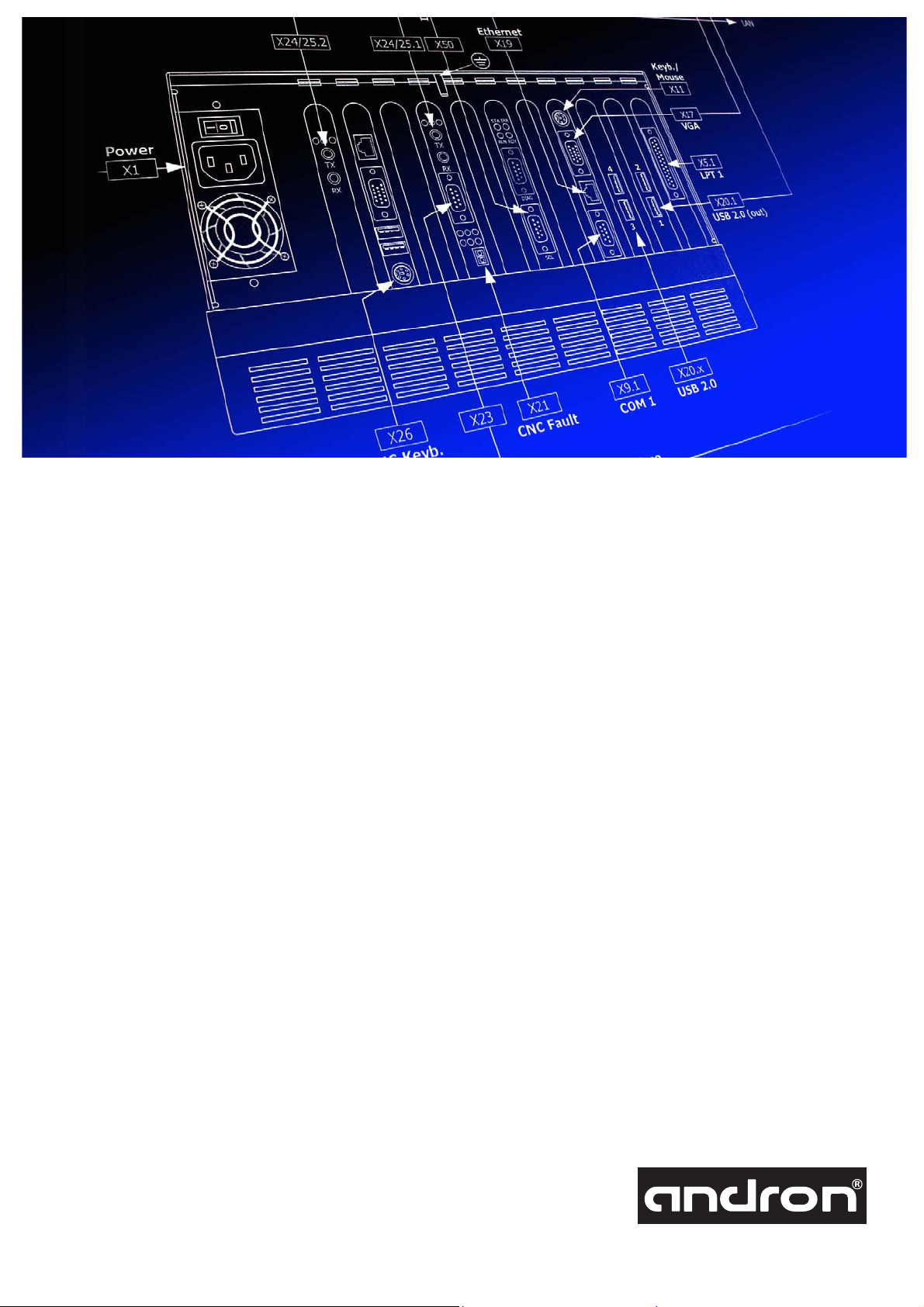
Connector and interface summary
X Interface Module Connector Connection
X1 Mains power supply Power supply 3-pin mains plug 100-240V, 50/60Hz
X2 24V Power Input Power supply 2-pol. connector 24V Input
X5.1 Parallel interface LPT1 HMI CPU 25-pin SUB-D connector (female)
X9.1 Serial interface COM1 HMI CPU 9-pin SUB-D connector (male)
X11 Keyboard/Mouse interface HMI CPU 6-pin PS/2TM connector (female)
X13 RPO Remote-Power-On/Off RPO adapter 4-pin terminal connector
X17.1 VGA interface HMI CPU 15-pin mini SUB-D con. (female) X17.1 ⇔ X60.1
X17.2 DVI interface HMI CPU DVI connector (female) X17.2 ⇔ X60.2
X19.1 Ethernet interface HMI CPU RJ-45 connector
X19.2 Ethernet interface HMI CPU RJ-45 connector
X19.5 EtherCAT interface (andronic 3060) HMI CPU RJ-45 connector
X20.x USB interfaces HMI CPU USB connector (Type A)
X21 CNC fault NCM card 2-pin terminal connector
X22 I/O Interface (option) NCIO card 37-pin SUB-D connector (female)
X23.1 NCM-NCIO Bus NCM card 9-pin SUB-D connector (female)
X23.2 NCM-NCIO Bus (option) NCIO card 9-pin SUB-D connector (male) X23.2 ⇔ X23.1
X24.1 SERCOS transmitter (TX) NCM card Fibre optic connector
X25.1 SERCOS receiver (RX) NCM card Fibre optic connector
X24.2 SERCOS transmitter (TX) OPT card Fibre optic connector
X25.2 SERCOS receiver (RX) OPT card Fibre optic connector
X26 Keyboard interface NC CPU 6-pin PS/2TM connector (female)
X27 I/O interface (only andronic 3060) NCM2 card 10-pin terminal connector
X30 Handwheel interface NCM card 9-pin SUB-D connector (male) to the handwheel
X40.x 4 USB interfaces ^ANV03 USB connector (Typ A) X40.x ⇔ X63
X41 USB interface (input) ^ANV03 USB connector (Typ B) X41 ⇔ X20.x
X42 ANV04 key pad (USB) ^ANV04 USB connector
X50 InterBus-S interface InterBus-S card 9-pin SUB-D connector (female) X50 ⇔ X70
X51 Diagnosis interface InterBus-S card 9-pin SUB-D connector (male)
X52 Profibus-DP interface Profibus card 9-pin SUB-D connector (female) X52 ⇔ X76
X60.1 VGA interface ^ANV03 15-pin mini SUB-D con. (female) X60.1 ⇔ X17.1
X60.2 DVI interface ^ANV03 DVI connector (female) X60.2 ⇔ X17.2
X62 Power supply 24V, DC ^ANV03 2-pin terminal connector 24V, DC (TFT)
X63 USB touch controller ^ANV03 USB connector (Typ B) X63 ⇔ X40.x
X70 InterBus-S interface (in) ^ANM013 9-pin SUB-D connector (male) X70 ⇔ X50
X71 InterBus-S interface (out) ^ANM013 9-pin SUB-D connector (female)
X72 16 Inputs ^ANM013 2 x 8-pin terminal connector
X73 16 Outputs ^ANM013 2 x 8-pin terminal connector
X75.1 Power supply 24V, DC ^ANM013 2-pin terminal connector 24V, DC (BTL)
X75.2 Power supply 24V, DC ^ANV03 2-pin terminal connector 24V, DC (USB)
X76 Profibus-DP interface * ^ANM013 9-pin SUB-D connector (female) X76 ⇔ X52
X80 Handpilot AHP interface LWI card RJ-45 connector X80 ⇔ (AHP)
X81.x Fibre optic generator interface LWI card 4x Fibre optic connector
02_basics_and_overviews.doc
Page 16

Basics and overviews
E
5
0
40
R
8
Technical Handbook andronic 2060
Survey of hardware components
andronic 2060S
24V DC
Power USB
X75.2
24V DC
24V DC
to the
drives
Power TFT
X62
Power BTL
X75.1
SERCOS (1st ring)
SERCOS (2nd ring)
X24/25.2
2
X24/25.1
95
90
100
105
110
115
120
%
III
SET
ALL
MOV
X70 X71
LPT1
USB 1.1
X5.1
X20.2
USB-HUB
(USB 2.0)
but only with USB 1.1
X40.4
X40.3
X40.2
External USB 1.1
devices (HD, floppy
memory stick, ...)
X40.1
X41
USB Touch
X63
VGA
X60
ANV03
I/O
X72
X73
A
B
C
Y
Z
X
.01 .001
.1
?
PLC
ANM012
16 Inputs
16 Outputs
InterBus-S
INTERBUS-S
INTERBUS-S
Power
110-
240 V AC
X1
TX
RX
TX
RX
STA ERR
RUN RDY
DIAG
SCL
X19
Ethernet
X17
VGA
X50
InterBus-S
LAN
X20.1
USB 1.1 (out)
X26
NC Keyb.
X23
CNC Fault
X21
X9.1
COM1
X11
Keyb./
Mouse
16 In / 16 Out
Fast I/O Interface
Illustration: Connection survey of the operating panel and the andronic 2060S control with further external devices
02_basics_and_overviews.doc
INTERBUS-S
Page 17

E
5
0
40
R
andronic 2060L
24V DC
Power USB
X75.2
Basics and overviews
Technical Handbook andronic 2060
9
24V DC
24V DC
to the
drives
Power
110-
240 V AC
USB-HUB
(USB 2.0)
X40.4
X40.3
X40.2
External USB 2.0
devices (HD, floppy
memory stick, ...)
X40.1
X41
USB Touch
X63
Power TFT
X62
ANV03
VGA
X60
I/O
16 Inputs
16 Outputs
INTERBUS-S
Power BTL
X75.1
95
90
2
100
105
110
115
120
%
III
A
B
SET
ALL
MOV
C
Y
Z
X
.01 .001
.1
?
PLC
ANM012
X72
X73
INTERBUS-S
X70 X71
InterBus-S
SERCOS (1st ring)
SERCOS (2nd ring)
InterBus-S
LAN
Ethernet
X24/25.2
X24/25.1
X50
X19
Keyb./
Mouse
X11
STA ERR
X1
TX
RX
TX
RX
RUN RDY
DIAG
1
2
X20.1
USB 2.0 (out)
X17
3
4
VGA
X5.1
LPT 1
SCL
X26
NC Keyb.
X23
X21
CNC Fault
X9.1
COM 1
X20.x
USB 2.0
16 In / 16 Out
INTERBUS-S
Fast I/O Interface
Illustration: Connection survey of the operating panel and the andronic 2060L control with further external devices
02_basics_and_overviews.doc
Page 18

Basics and overviews
10
Technical Handbook andronic 2060
Survey of the operating panel connections
External USB devices
(HD, floppy, memory stick, ...)
Power USB
X75.2
24V DC
USB-HUB
(USB 2.0)
X40.x
X40.1
USB
X63
24V DC
X62
2
1
Power TFT
GND
+24 V
Power BTL
X75.1
24V DC
ANV03
InterBus-S version (BTL09)
X41
InterBus-S cable
X70
VGA
USB Touchcontroller
X60
VGA cable
USB cable (aktive/passive)
X71
X17
X20.1
X50
HMI CPU
HMI CPU
InterBus-S
interface
ANM013
X72X73
16 Outputs
02_basics_and_overviews.doc
16 Inputs
InterBus-S devices
further
Page 19

Block diagram
CNC fault
1 - 2 SERCOS rings
1 - 2 Handwheels
Basics and overviews
Technical Handbook andronic 2060
NC computer HMI computer
Operating panel + 16 I/O´s USB touch controller
NCM board
PCI
16 I/O´s
NCIO board
(optional)
NC CPU board
PCI PCI PCI
External I/O´s TFT display
InterBus-S board
HMI CPU board
11
COM 1, USB 1.1
Ethernet
IDE hard disk drive
Optional (external)
USB hard disk drive
USB memory stick
USB floppy drive
USB CD/DVD-ROM
USB CD writer
2 divided backplane
with PCI to PCI bridge
NC BUS
Illustration: Block diagram of the andronic 2060s
NC computer HMI computer
CNC fault
Fast I/O´s
1 - 4 SERCOS rings
1 - 4 Handwheels
NCM board
PCI
NC CPU board
PCI
PCI
HMI BUS
PCI
Operating panel + 16 I/O´s USB touch controller
External I/O´s TFT display
Reserve
PCI PCI
Reserve
PCI PIGMG
InterBus-S board
HMI CPU board
Schema andronic 2060s-E.eps
COM 1, USB 2.0
Ethernet
IDE hard disk drive
Optional (external)
USB hard disk drive
USB memory stick
USB floppy drive
USB CD/DVD-ROM
USB CD writer
2 divided backplane
with PCI to PCI bridge
NC BUS
PCI
HMI BUS
PCI
Illustration: Block diagram of the andronic 2060L
02_basics_and_overviews.doc
Schema andronic 2060l-E.eps
Page 20

Basics and overviews
12
Technical Handbook andronic 2060
Overview of the units
Front view of the andronic 2060S
Power Supply 300 W
100-240 V, 50/60 Hz
NTGE0060
LED
- 5V
+ 5V
+12V
+ 3.3V
- 5V
OPT
128 MB SDRAM
+PCB0602
NC-CPU
NCM
NCIO (opt.)
HMI-CPU
INTERBUS-S
+LÜF0101
1234
Illustration: Open housing of the andronic 2060S
02_basics_and_overviews.doc
HD 2(Option)
HD 1
Page 21

Front view of the andronic 2060L
Basics and overviews
Technical Handbook andronic 2060
13
Power Supply 300 W
100-240 V, 50/60 Hz
NTGE0060
OPT
NC-CPU
NCM
HMI-CPU
INTERBUS-S
HD 2(Option)
HD 1
- 5V
+ 5V
+12V
+ 3.3V
- 5V
128 MB SDRAM
HD Power
+5V
GND
+5V
GND
256 MB DDR RAM
2x
PW1
LED
+PCB0601
+LÜF0101
1234
Illustration: Open housing of the andronic 2060L
02_basics_and_overviews.doc
Page 22

Basics and overviews
14
Technical Handbook andronic 2060
Computer dimensions
312.0
329.0
214.0
160.0
171.5
Klappdeckel nicht abnehmbar
Hinged lid not removable
428.5
377.5
394.5
293.0
235.0
171.5
494.0
Klappdeckel nicht abnehmbar
Hinged lid not removable
02_basics_and_overviews.doc
Page 23

R
Operating panel dimensions
ANV03
65.0
41.5
482.6 (19")
15" TFT-Display
424.0
Basics and overviews
Technical Handbook andronic 2060
113.0
15
ANV04
65.0
41.5
USB-HUB
USB-HUB
260.0
260.0
(7HE)
273.0
310.5
272.8
155.3
38.0
ANV03
37.8
482.6 (19")
424.0
113.0
7 8 9
456
123
+
0.
α
Esc
Del
15" TFT-Display
273.0
38.0
Ins
Ctrl
Alt
Help
Enter
End
ANV04
(7HE)
310.5
272.8
37.8
ANM013
8.8
10.0
5.5
95
90
80
%
100
100
85
90
100
110
120
+
105
80
110
70
115
60
120
50
%
III
A
B
SET
ALL
MOVE
C
Y
Z
X
.01 .001
.1
?
PLC
ANM012
101.3
241.3
55.0
90.0
139.0
60
40
8.8
20
10
6
2
0
0
!
381.3
02_basics_and_overviews.doc
8.8
37.7
139.3
(4HE)
177.0
Page 24

Basics and overviews
16
Technical Handbook andronic 2060
Technical data
HMI computer andronic 2060L andronic 2060S
CPU card Full-Size slot CP U
Hard disk drive 120 GB / 2.5 inch 120 GB / 2.5 inch
PLC integrated soft PLC (CoDeSys) integrated soft PLC (CoDeSys)
I/O interfaces InterBus-S / Profibus-DP InterB us-S / Profibus-DP
Operating system
NC computer
CPU card Half-Size slot CPU
NCM card NC multifunction card NC multifunction card
Interfaces Handwheel
Celeron M / 1.6 GHz or
Pentium M /1.8 GHz
512/1024 MB DDR RAM
Graphic, Ethernet and
IDE controller onboard
USB 2.0
®
Microsoft Windows
Celeron 1.2 GHz or Celeron M 1.6 GHz
128 MB RAM
Fast inputs for:
Emergency stop, stop, release,
measuring signal
Opener for “Fault“
SERCOS interface (optical) up to 4
rings
2000/XP® Microsoft Windows® 2000/XP®
Half-Size slot CPU
Celeron / 1.2 GHz or Celeron M 1.6 GHz
256/512 MB RAM
Graphic, Ethernet and
IDE controller onboard
USB 1.1/2.0
Half-Size slot CPU
Celeron 1.2 GHz or Celeron M 1.6 GHz
128 MB RAM
Handwheel
Fast inputs for:
Emergency stop, stop, release,
measuring signal
Opener for “Fault“
SERCOS interface (optical) up to 2
rings
Operating system andron realtime op. system andron realtime op. system
General
Internation Protection IP 20 IP 20
Input voltage 100-240 V AC, 50/60 Hz 100-240 V AC, 50/60 Hz
Power consumption max. 300 VA max. 300 VA
Temperature range +5°C … +45°C +5°C … +45°C
Dimensions 293 x 394.5 x 171.5 (WxHxD) 214 x 329 x 171.5 (WxHxD)
Operating panels ANV03/ANV04 ANM013/ANM002
Protection IP 64 (front), IP 20 IP 64 (front), IP 20
Input voltage 24 V DC 24 V DC
Power consumption max. 75 VA max. 225 VA
Temperature range +5°C … +45°C +5°C … +45°C
02_basics_and_overviews.doc
Page 25

Connection Requirements
Page 26

Connection Requirements
2
Technical Handbook
Editing/Illustrations Pa
Version V 5.2
Date 01.02.2007
Author Vo/Pa
Tools This documentation was created with Microsoft Word 2000 and Adobe Illustrator.
Trade mark All product names or trademarks are properties of their respective owners.
Copyright © andron GmbH 2007. All rights reserved.
Validity There could be additional functions running in the control who are not mentioned in this documentation. It insists no
Published by andron GmbH, Schlätterstr. 2, D-88142 Wasserburg/Bodensee
Copying this document, giving it to others and the use or communication of the contents thereof without express
authority, are forbidden. Offenders are liable for the payment of damages. All rights are reserved in the event of the
grant of a patent or the registration of a utility mode l or design.
claim for this functions, in case of a new delivery or a service case.
All rights are reserved with respect to the content of this documentation and the availability to the product.
Telephone +49 (0) 8382/9855-0, Fax +49 (0) 8382/9855-50
e-Mail:
info@andron.de
www.andron.de
03_connection_requirements.doc
Page 27

Connection Requirements
Technical Handbook
Table of contents
Revisions........................................................................................................................................................ 3
General connection requirements..................................................................................................................... 4
Static Electricity..............................................................................................................................................5
Dust and Dirt.................................................................................................................................................. 5
Transport and Mounting.................................................................................................................................. 5
Display....................................................................................................................................................5
Operating panel.......................................................................................................................................5
Electronic Rack / Operating Panel .................................................................................................................... 6
Mounting positions .................................................................................................................................. 6
Location.........................................................................................................................................................6
Mains Connection ........................................................................................................................................... 7
Important information on wiring...................................................................................................................... 8
Shielding and Grounding .................................................................................................................................9
Interference Suppression .............................................................................................................................. 10
Alternating current......................................................................................................................... 10
Direct current ................................................................................................................................ 10
Non-contacting switches (Initiators)........................................................................................................ 11
Mechanical switches .............................................................................................................................. 11
Creeping contacts.................................................................................................................................. 11
Adjustment................................................................................................................................................... 11
Connection values......................................................................................................................................... 12
Operating and ambient conditions.................................................................................................................. 12
Revisions
Version Date Additions and changes Initials
V 5.0 08.07.2003 Revised version Pa
Changes:
V 5.1 16.07.2003
V 5.2 01.02.2007 Layout change to DIN A4 Pa
Operating and ambient conditions
Temperature: Storage/Transport -20°C ... +45°C
Pa
3
03_connection_requirements.doc
Page 28

Connection Requirements
4
Technical Handbook
General connection requirements
The following notes generally must be observed:
Inputs with safety functions (e. g. release feed, emergency stop, ...) must be
All connections are to be made according to the information contained in the
documentation of the control.
Make sure that all soldering points are clean.
Only shielded cables may be used.
The shielding is to be carried out according to the requirements (see "Shielding").
Emergency stop and limit switches must always be designed as break contacts, in
order to cause the control to stop immediately in case of a connecting cable break.
The control is not a mediate Emergency Stop switching element; i. e. an
Emergency Stop must also suspend all movements of a machine immediately
even without a control!
absolutely connected to the control and switches, and the cables must have been
checked as well for their function before the first turn on.
Safety switches must always be connected in series (e. g. emergency stop circuit).
Drives with closed control circuits must have, in addition to limit switches, also
mechanical safety limit switches following those in the path. These must be handled
electrically like an EMERGENCY STOP and must be integrated into the available
emergency stop loop.
Work on the control and the electrical connections may
only be performed with the supply voltage turned off
and by qualified personnel!
03_connection_requirements.doc
Page 29

Connection Requirements
Technical Handbook
5
Static Electricity
When installing or replacing hardware components, you should always discharge the static
electricity on your body as it can cause damage to electronic components or even to entire
assemblies. To discharge the static electricity, touch the metal of the control.
Electronic components such as ICs and memory modules on the pc-boards are very
sensitive to static electrical discharges and are easily damaged by them. Be sure that the
service personnel are suitably grounded before they touch pc-boards and pcb-components.
The drier the surroundings, the more likely it is that static electricity occurs.
When replacing plug-on cards, don't contact the components on the cards or their "golden
fingers". Before components and assemblies are inserted or connected, the control must be
built-in and grounded via the ground stud.
Please handle all electrostatically sensitive pc-boards and assemblies only at
a secured working area.
Use only ESD shielding bags for transporting and handling
pc-boards and components.
Dust and Dirt
Malfunctions in many cases result from dusty, polluted or greasy contacts. Proper
functioning of the control can only be ensured when all components are treated with the
necessary care. When replacing a pc-board pay special attention to the gold-plated contact
surface of the BUS connector as it oxidises rapidly when touched. Use an eraser to clean
the surface when it is dirty.
Transport and Mounting
Instructions for securing it with the available transport safety devices must be observed.
Hard shocks must be prevented under all circumstances, because the display and the builtin hard disk could encounter irreversible damage.
It must be absolutely precluded that electronic components and pc-boards are exposed to
the danger of shorting (wetness, accidental grounding by improper handling and storage
during operation)
Display
Although the electronics and high tension conducting parts of the display are protected
The display must be protected from mechanical loads and shocks.
from being touched by a sheet-steel housing, the following notice is expressly given:
The internal space of the display housing can also be under high tension after
the power has been turned off! The device may only be opened at the factory.
Operating panel
03_connection_requirements.doc
Be careful when mounting the operating panel that the foil is not damaged (e. g. by
pointed or sharp tools, soldering iron, ...).
Page 30

Connection Requirements
T
6
Technical Handbook
Electronic Rack / Operating Panel
An electronic rack sealed according to IP 54/55 with a heat exchanger or an air conditioner
is to be used. The admissible environmental temperature of 45°C for the control in the
electronic rack must not be exceeded. Free circulation of air in the rack must be
guaranteed. In order to guarantee a sufficient ventilation, approx. 100 mm space along the
full width must be left free above and at the front of the control.
High frequency generators, transformers, power generators etc., must not be installed in
the immediate vicinity of the control.
Mounting positions
When mounting the control in the electronic rack or in the operating panel only the
following
mounting positions are allowed.
Location
Illustration: Allowed mounting positions of the con ol modul t
he location of the control is decisive for its proper functioning. The mounting instructions
and the connection instructions therefore must be exactly followed. In case of doubt,
contact our service technicians who will be glad to assist you.
The most important mounting instructions are:
The installation must be performed without heavy shocks. The position of
the control must be such that there are no shock influences, otherwise the
built-in hard disk or the display could be damaged.
The control should not be exposed to external heat sources (e. g. strong
sunshine, heat blowers, etc.); its maximum admissible ambient temperature
= 45°C.
is T
amb
Before turning on the control, ensure that the mains voltage corresponds to
the admissible operating voltage of the control.
Ensure that the mains connection is non-disruptive. If the mains voltage
conditions are critical, a constant voltage controller must absolutely be
used. When checking the mains condition, a full daily routine or a multi-shift
period must be considered.
03_connection_requirements.doc
Page 31

Connection Requirements
Technical Handbook
7
Mains Connection
The mains voltage must correspond with the admissible operating voltage of the control.
This is achieved by connection to the 230 V mains or via a transformer 400/230V
(50/60 Hz).
For installation in the U.S.A., the mains voltage is 115 V.
The mains voltage supplied to the control must not have the same phase as contacts,
relays and other switching elements or devices of the control cabinet.
L1
L2
L3
N
PE
115V/230V
1 2
Trennung.eps
Illustration: Mains power supply of the control connected with a different phase
1 Relays, con actors, magnetic valves, ... t
2 Control
All transformers used must be provided with a protective winding connected to a ground
wire. Thus, the danger of a voltage flashover between windings is decreased and the noise
ratio is also enhanced.
By using U-sections with separate side windings (one side prim., one side sec.), the
protective winding can be omitted.
If the mains voltage conditions are critical, a constant voltage controller must be absolutely
used. When selecting it, the power consumption of the control must be taken into account!
On request, we will deliver suitable transformers or constant voltage controllers.
In general, the regulations of the local electric supply company are to be observed.
03_connection_requirements.doc
Page 32

Connection Requirements
8
Technical Handbook
Important information on wiring
The ground cables must be connected first to divert the static electricity.
For all signal lines, shielded cables are to be used, whereby the shields must only be
connected to the metal connector housing of the connectors on the control side.
For all signal lines, the minimum line cross-section must not be less than 0.25 mm
2
.
All line cross-sections must correspond to the guidelines of the VDE 0113.
Make sure that all solder and squeeze connections are perfectly in order. All
connections are to be established according to our documentation.
All SUB-D connectors must be screwed to the housing.
Mains connection minimum 3 x 1.5 mm
SL connection to the ground stud min. 4 mm
SL busbar to the ground potential minimum 16 mm
2
2
2
The fibre-optic and coaxial cable must not be bent. When laying it, the minimum
bending radius must be not be less than the indicated value.
The bending radius of the SERCOS fibre-optic cable must not be less than 50 mm.
Please note also the information in the respective
chapters of the hardware description
Special care should be taken with reference to the outputs which lead to relays, contactors,
valves, timer switching devices, etc.
The input and output lines should be generally as short as possible and laid at a
distance to high tension lines.
The cable trees for load and control circuits should also be laid separately!
1
Illustration: Separate layout of load and control cables
1 Load circuits (Relays, con actors, valves, ...)
2 Control circuits (Control, ...)
t
03_connection_requirements.doc
2
Last- und Steuerkreis.eps
min. 30 mm
Page 33

Connection Requirements
Technical Handbook
9
Shielding and Grounding
All shields may only be connected on the side of the signal source and must be combined
by means of a ground cable busbar (clamping strip) and connected jointly to the ground
cable potential. The grounding and shielding connections must be established as shown in
the following illustration.
min.
2
O 4mm
Quelle
(Source)
Quelle
(Source)
min. O 16mm
2
PE-Sammelschiene.eps
Illustration: Shielding and grounding of the modules
For all signal cables connected to the control, the shielding is provided on the
control side. For this, only the mating connector and housing made of metal
(conducting) material may be used. The grounding is achieved via the shield on
the connector housing to the PE (SL) busbar.
Illustration: PE ground connection o the control module f
Proper ground connection to the computer and the
operating panel must be ensured.
03_connection_requirements.doc
Observe the VDE regulations!
Page 34

Connection Requirements
10
Technical Handbook
Interference Suppression
When the above mentioned instructions are followed, interference sources can be almost
entirely excluded. However, in spite of care and cabling according to the instructions, the
following section on interference reduction is to be absolutely observed.
Alternating current Switching contactor coils can cause interference in the supply lines. Therefore, especially in
alternating current protective systems via an RC member or varistors parallel to the coils,
interference reduction measures are to be performed.
Guide values for 230 V contactors:
R=100 ohms, C=0.1 µF, U=630 VAC
Direct current • All direct current coils, (relays, solenoids) on the machine must be provided with an
anti-surge diode. This anti-surge diode must be connected in the immediate vicinity
of the coil. The correct polarity must be observed.
-
CR
Varistor
+
Spulen.eps
Illustration: Interference reduction on coils n an alternating and direct current circuit i
We want to emphasise that we assume no liability for proper functioning or any
damage when these instructions have not been followed!
03_connection_requirements.doc
Page 35

T
Non-contacting switches (Initiators)
Mechanical switches
Creeping contacts
The quality of the output signals of the non-contact switches is decisive for the perfect
functioning of the control electronics. In order to prevent oscillation tendencies at the
output of these switches, only stabilized supply voltages may be employed. The neutral
conductor to the initiators must be achieved by connection to the neutral point of the
power supply.
• With mechanical switches, only those with spring contacts should be used. Take
care that the contact pressure and contact material is suitable for the
corresponding switching current.
In general, interference suppression is to be performed for every sink. The
procedures recommended by the manufacturer are to be performed and the
corresponding interference material is to be built in. If these interference
suppression measures are not carried out, malfunctions cannot be excluded.
This is also valid for contactors.
Creeping contacts are often found in pressure and temperature switches. These cause
especially hard to locate disturbances when they take on an instantaneous undefined state
during switching from the "ON" to the "OFF" state and an arc path occurs ("spattering").
hey create electromagnetic waves, as in a spark transmitter, when an inductive load
follows. In such cases, spring switches or non-contacting switches must be installed.
Connection Requirements
Technical Handbook
11
Adjustment
Every machine-specific parameter, except for the adjustment of the drive, is adjusted in the
EEPROM by means of a separate alphanumeric keyboard. No changes must be made on the
individual cards.
Before the first movement of the axes, the following parameters in the EEPROM are
If there is a modification to the cards, not made by one of andron's authorised
service personnel, all guarantees and claims for service under the guarantee are
void.
absolutely to be checked and, as the case may be, to be adapted:
Resolution of the axes
Axes limitations
Speeds
Zero traversing sequence
Ramp curve
Furthermore, it must be ensured that the limit switches are connected to the correct inputs
and are functioning properly. Likewise, this is valid also for the EMERGENCY STOP switch.
In order to prevent damage in the first movement, it must be observed that the override
potentiometer is approx. at the 10% position and that creep traversing mode has been
selected.
We assume no liability for damage, when the connection requirements have not
been fulfilled or have been performed by unauthorised service personnel!
03_connection_requirements.doc
Page 36

Connection Requirements
12
Technical Handbook
Connection values
Computer power supply Input voltage 100-240 V AC, 50/60 Hz
Power consumption max. 300 VA
Display power supply Input voltage 24 V DC, +/- 10%
Power consumption max. 75 VA
USB-Hub power supply Input voltage 24 V DC, +/- 10%
Power consumption max. 75 VA
Input voltage 24 V DC, +/- 10% Operating panel ANM013
Power consumption max. 225 VA
Operating and ambient conditions
In operation Storage/Transport
Ambient temperature +5°C ... +45°C -20°C ... +45°C
03_connection_requirements.doc
Page 37

Operating panel modules
Page 38

Operating panel modules
2
Technical Handbook andronic 2060/3060
Version V 1.2
Date 26.05.2010
Author Pasternak
Editing/Illustrations Pasternak
Tools This documentation was created with Microsoft Word and Adobe Illustrator.
Trade mark All product names or trademarks are properties of their respective owners.
Copyright © andron GmbH 2010. All rights reserved.
Validity There could be additional functions running in the control who are not mentioned in this documentation. It insists no
Published by andron GmbH, Schlätterstr. 2, D-88142 Wasserburg/Bodensee
Copying this document, giving it to others and the use or communication of the contents thereof without express
authority, are forbidden. Offenders are liable for the payment of damages. All rights are reserved in the event of the
grant of a patent or the registration of a utility model or design.
claim for this functions, in case of a new delivery or a service case.
All rights are reserved with respect to the content of this documentation and the availability to the product.
Telephone +49 (0) 8382/9855-0, Fax +49 (0) 8382/9855-50
e-Mail: info@andron.de
www.andr
on.de
04_operating_panel_modules.doc
 Loading...