

Page 1
V 6.05.08.02
G&M Code Programming Manual
Page 2

2
andronic 2060/30 60
G&M Code Programming Manual
Version
V 6.05.08.02
Release Date
26.07.2013
Author(s)
Vol/Scho/Vo
Editing/Illustrations
Pa
Trademark
All product names and trademarks are the exclusive possession of their respective owners.
Protection no te
© andron GmbH 2013. All Rights Reserved.
Liability
There may be fur ther co ntrol funct ions th at are ope rational b ut not des cribed in this doc umentatio n. No leg al right
Published by
andron GmbH, Schlätterstraße 2, 88142 Wasserburg, Germany
A member of the LTi group of companies
Passing on and copy ing t his doc umen t, uti liz atio n and c om munic at ion o f its co nten ts is not allow ed, un less expl icitly
authorized. Violators are liable for damages. All rights, especially if a patent is granted or a utility model is
registered, are reserved.
exists, however, to these functions when a new system is delivered or the system is serviced.
The contents of this documentation and the delivery options of the products are subject to modifications.
Telefon +49 (0) 8382/9855-0, Fax +49 (0) 8382/9855-50
e-Mail: info@andron.de
www.andron.de
gm_code_programming_manual_v6.05.08.02.doc
Page 3

andronic 2060/30 60
3
G&M Code Programming Manual
Content
Content ..................................................................................................................................................................... 3
Revisions................................................................................................................................................................... 6
General information .................................................................................................................................................. 7
Address letters ............................................................................................................................................................. 7
Safety instructions .................................................................................................................................................... 8
Warnings and symbols ................................................................................................................................................. 8
Designated use ............................................................................................................................................................ 9
Use of the unit contrary to its designated use ................................................................................................................ 9
Components of a NC program ................................................................................................................................. 10
Tool management ................................................................................................................................................... 11
Functions of the tool management .............................................................................................................................. 11
Duplo tools ........................................................................................................................................................ 11
Tool data ................................................................................................................................................................... 11
M Functions ............................................................................................................................................................ 14
Extensions of M commands (option) ............................................................................................................................ 15
G Functions ............................................................................................................................................................. 16
Explanations .............................................................................................................................................................. 16
G00 Positioning in rapid traverse ................................................................................................................................. 17
G01 Positioning at the feed rate .................................................................................................................................. 18
G02 Circular interpolation - Clockwise .......................................................................................................................... 19
G03 Circular interpolation - Counterclockwise............................................................................................................... 19
G04 Dwell time .......................................................................................................................................................... 20
G05 Spatial arc interpolation ....................................................................................................................................... 21
G14 Macro call ........................................................................................................................................................... 22
G17 Plane XY ............................................................................................................................................................. 23
G18 Plane ZX ............................................................................................................................................................. 23
G19 Plane YZ ............................................................................................................................................................. 23
G22 Sub program call ................................................................................................................................................. 24
G23 Text - Functions .................................................................................................................................................. 25
G25 RTCP H On/Off .................................................................................................................................................... 26
G26 Free plane .......................................................................................................................................................... 29
G29 Axis transformation ............................................................................................................................................. 32
G30 Spline interface (online spline) ............................................................................................................................. 34
G305 P5-Interpolation (Online Polynomial) .................................................................................................................. 35
G31-G35 Spline interface (offline spline) ...................................................................................................................... 36
G40 Deletion of the milling cutter radius correction ...................................................................................................... 37
G41 Milling cutter radius correction left ....................................................................................................................... 38
G42 Milling cutter radius correction right ..................................................................................................................... 39
G43 Milling cutter radius correction up to..................................................................................................................... 40
G44 Milling cutter radius correction via ........................................................................................................................ 41
Zero offsets and coordinate rotation ............................................................................................................................ 42
G50/G51/G52 P R ESET ................................................................................................................................................ 43
G50 Deactivate PRESET .............................................................................................................................................. 44
G51 activate PRESET .................................................................................................................................................. 45
G52 program PRESET ................................................................................................................................................. 46
G53 Deletion of the zero offset ................................................................................................................................... 47
G54 - G59 Zero offset and coordinate rotation ............................................................................................................. 48
G70 Units of measurement inch .................................................................................................................................. 50
G71 Units of measurement mm ................................................................................................................................... 51
G72 Deletion of mirror image machining and scaling .................................................................................................... 52
G73 Mirror image machining ....................................................................................................................................... 53
G73 Scaling ............................................................................................................................................................... 54
G77 Cycle execution on a circle ................................................................................................................................... 55
G78 Point definition .................................................................................................................................................... 56
G79 Cycle execution ................................................................................................................................................... 57
gm_code_programming_manual_v6.05.08.02.doc
Page 4

4
andronic 2060/30 60
G&M Code Programming Manual
General cycle definition (drilling and milling cycles) ...................................................................................................... 58
G81 Drilling cycle ....................................................................................................................................................... 59
G83 Deep-hole drilling cycle ........................................................................................................................................ 60
G84 Tapping cycle ...................................................................................................................................................... 62
G87 Rectangular pocket milling cycle ........................................................................................................................... 64
G88 Slot milling cycle.................................................................................................................................................. 66
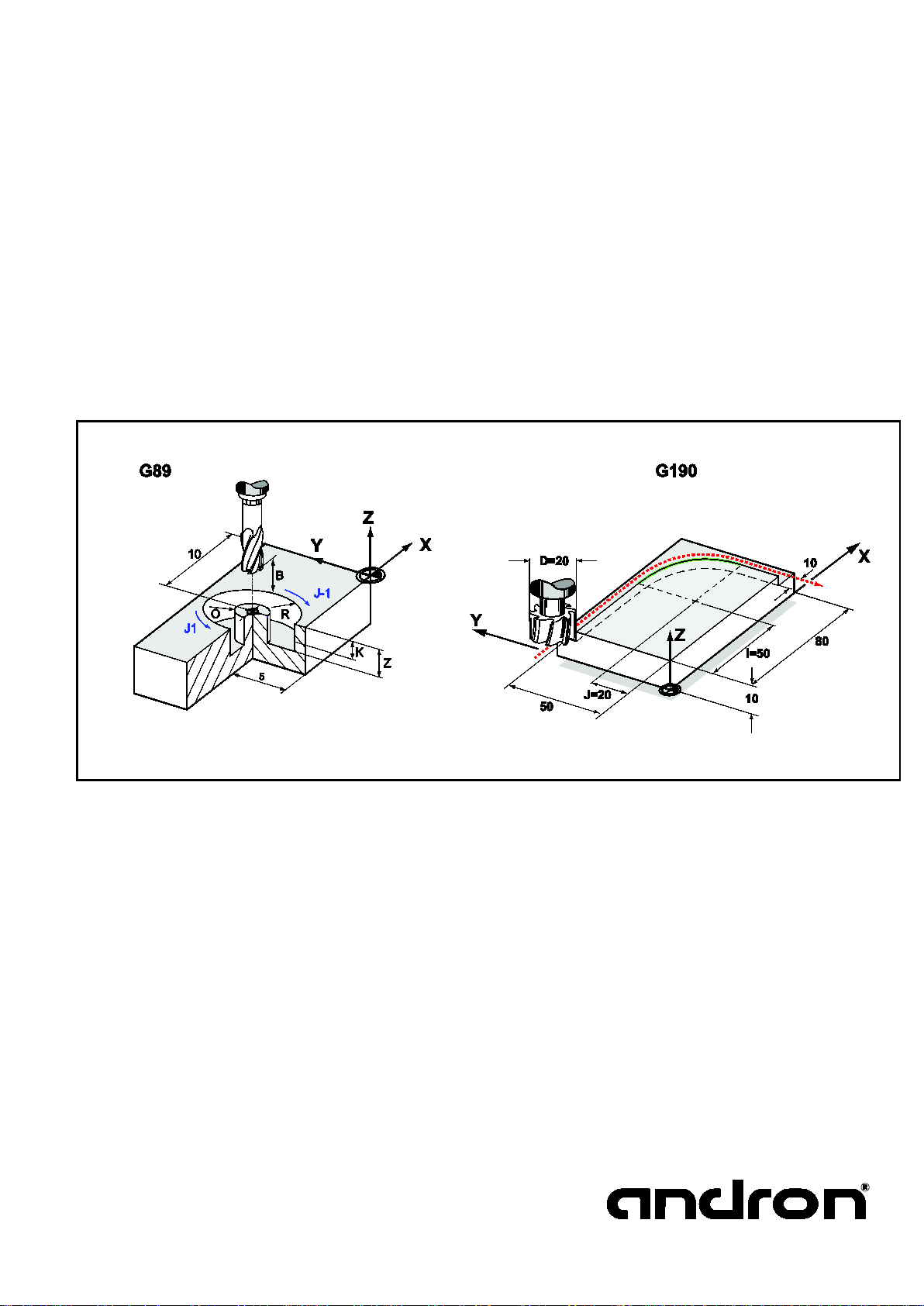
G89 Circular / ring pocket milling cycle ........................................................................................................................ 68
G90 Absolute measure ................................................................................................................................................ 70
G91 Relative measure ................................................................................................................................................. 71
G92 Relative zero point offset coordinate rotation ........................................................................................................ 72
G93 Absolute zero point offset coordinate rotation ....................................................................................................... 73
G94 Speed programming ............................................................................................................................................ 75
G95 Time programming .............................................................................................................................................. 76
G110 PLC Output setting ............................................................................................................................................ 77
G111 PLC Output deleting ........................................................................................................................................... 77
General cycle definition (measuring and setup cycles) .................................................................................................. 80
G181 Probe calibration................................................................................................................................................ 81
G182 Distance measurement ...................................................................................................................................... 87
G183 Straight line probing .......................................................................................................................................... 89
G184 Shaft probing .................................................................................................................................................... 91
G185 Bore probing ..................................................................................................................................................... 93
G186 Point measurement ............................................................................................................................................ 95
G187 Measuring plate calibration ................................................................................................................................. 97
G188 Tool length measuring plate ............................................................................................................................. 101
G189 Tool breakage control measuring plate ............................................................................................................. 103
G190 Absolute circle center ....................................................................................................................................... 105
G191 Relative circle center ........................................................................................................................................ 106
G281 Ramp participation........................................................................................................................................... 107
G282 Coordinates ..................................................................................................................................................... 108
G282,0 Switching workpiece coordinate system WCS / machine coordinates system MCS ............................................. 108
G282,1 Resynchronising axis positions of active NC processes ..................................................................................... 108
G282,2 Modulo on / off ............................................................................................................................................. 109
G283 Multi-axis probing ............................................................................................................................................ 110
G285 Probe SETPOS ................................................................................................................................................. 113
G286 Look Ahead Switch On/Off ............................................................................................................................... 116
G288 Set Look Ahead parameters ............................................................................................................................. 117
G288,0 LookAhead basic parameter .................................................................................................................. 117
G288,1 time-based axes ................................................................................................................................... 118
G288,2 Rounding axis ...................................................................................................................................... 119
G288,3 Contour accuracy of individual axes ....................................................................................................... 120
G288,4 Time base factor is axis-specific ............................................................................................................ 121
G289 Multi-function cycle .......................................................................................................................................... 122
G289 C Disable execution of external cycles ............................................................................................................... 123
G289 E Error Exit from G&M code.............................................................................................................................. 124
G289 L Tool length correction ................................................................................................................................... 125
G289 N Reload PRCON ............................................................................................................................................. 126
G289 R Adopt tool radius .......................................................................................................................................... 127
G289 X Adopt measurement values ........................................................................................................................... 128
G289 Z Enabling of G73 / G93 with cycles .................................................................................................................. 129
G481 Bore setup ...................................................................................................................................................... 130
G481 SE01 setup 2 bores .......................................................................................................................................... 132
G481 SE02 setup 4 bores .......................................................................................................................................... 133
G482 Shaft setup ..................................................................................................................................................... 135
G482 SE03 Setup 2 shafts ......................................................................................................................................... 137
G482 SE04 Setup 4 shafts ......................................................................................................................................... 138
G483 Setup slot/rectangular pocket inside ................................................................................................................. 140
G484 Setup slot/rectangle outside ............................................................................................................................. 143
G485 Setup 2 sides .................................................................................................................................................. 146
G487 Determine space point ..................................................................................................................................... 149
G488 Simple measurement block............................................................................................................................... 152
G581 Continuous operation cycle rotation .................................................................................................................. 156
G582 Continuous operation cycle oscillation ............................................................................................................... 157
G585 Position log ..................................................................................................................................................... 159
G586 Activation of job list processing ........................................................................................................................ 160
G586 Job list processing ........................................................................................................................................... 160
G587 I Variable -> PLC ............................................................................................................................................. 161
G587 O Set feed/spindle potentiometer ..................................................................................................................... 162
G589 Approach reference point ................................................................................................................................. 163
gm_code_programming_manual_v6.05.08.02.doc
Page 5

andronic 2060/30 60
5
G&M Code Programming Manual
G688 Setup command - Workpiece Machining ............................................................................................................ 164
G688,2 Surface plane milling ................................................................................................................................... 165
G688,3 Frame milling .............................................................................................................................................. 166
G688,10 Thread milling ........................................................................................................................................... 167
G781 Calibration OFFSET .......................................................................................................................................... 169
G781,1 Spindle offset ............................................................................................................................................... 173
G782 Read/write data of the CNC ............................................................................................................................. 174
G782,0 / ,1 Data of the tool management ................................................................................................................. 174
G782,0 I/R Read data of the CNC .............................................................................................................................. 175
G782,0 E Adjust error reaction cycles ........................................................................................................................ 176
G782,1 Write data of the CNC ................................................................................................................................... 177
G782,2 Read PLC variables ....................................................................................................................................... 178
G782,3 Write PLC variables ....................................................................................................................................... 179
G782,4 Read axis position ........................................................................................................................................ 180
G782,5 Read definition of the external cycle interface ................................................................................................ 181
G782,6 Reading the execution definition of the external cycle interface ....................................................................... 182
G782,8 Read sercos parameter ................................................................................................................................. 183
G782,9 Checking the assignment of communication variables ..................................................................................... 184
G782,10 Reading the active offsets ........................................................................................................................... 185
G783,0 Read/Write zero points ................................................................................................................................. 186
G784,0 Read in communication variable .................................................................................................................... 187
G784,1 Emit communication variables ....................................................................................................................... 188
G787 Apaptive Control .............................................................................................................................................. 189
G788,1 Probing the surface Z axis ............................................................................................................................ 190
G788,2 Corner and angle against the positive X axis ................................................................................................. 191
G788,3 Rectangle centre point and angle against X – individual measurement ............................................................ 192
G788,5 Rectangle centre point and angle against X – follow-up measurement ............................................................ 193
G788,10 Detecting the surface using 3 points (optional) ............................................................................................ 195
G789 Timer cycles .................................................................................................................................................... 196
Block search .......................................................................................................................................................... 198
Job list .................................................................................................................................................................. 201
Usage options .......................................................................................................................................................... 201
Inputs ..................................................................................................................................................................... 201
Usage notes .................................................................................................................................................... 202
Start of the job list ................................................................................................................................................... 203
Syntax: ........................................................................................................................................................... 203
Parameter programming ...................................................................................................................................... 204
Flexible G&M code Programming (FlexProg) ........................................................................................................ 205
General ................................................................................................................................................................... 205
Restrictions .............................................................................................................................................................. 206
General program structure ........................................................................................................................................ 206
Data types ............................................................................................................................................................... 206
Functions (general) .................................................................................................................................................. 207
Function declaration ................................................................................................................................................. 207
Macros and Q parameters ........................................................................................................................................ 207
Function definition ................................................................................................................................................... 208
Variables ................................................................................................................................................................. 208
Communication variables .......................................................................................................................................... 209
Status of communication variables ............................................................................................................................ 209
Expressions and operators ........................................................................................................................................ 210
Mathematical funktions ............................................................................................................................................. 210
Assignment of NC addresses ..................................................................................................................................... 211
Comment marks....................................................................................................................................................... 211
Point definition ......................................................................................................................................................... 211
Instructions ............................................................................................................................................................. 212
Jump marks ............................................................................................................................................................. 212
GOTO/IF ... GOTO/ IF ELSE ...................................................................................................................................... 212
FOR loops ................................................................................................................................................................ 213
WHILE loops ............................................................................................................................................................ 213
DO ... WHILE loops .................................................................................................................................................. 213
SWITCH ... CASE branching ...................................................................................................................................... 214
Sample programs ..................................................................................................................................................... 215
Index .................................................................................................................................................................... 229
gm_code_programming_manual_v6.05.08.02.doc
Page 6
6
andronic 2060/30 60
G&M Code Programming Manual
Version
Date
Additions and changes
Initials
New chapter: G782,8
•
• new structure G688
• Corrections / extensions:
• New chapter: Tool management, job list, G688,x, G788,x
• Corrections / extensions: G 586
• Corrections / extensions: Zeropoints, G29, G189, G481, G485, G781
• New: G585
• Corrections / extensions: G22, G23, G50, G181, G282,0/G282,2 and G781
• New: G29, G305, G787
• Corrections: G17-G19, G50/G51/G52 PRESET, G92, G289, G488
• New: G23, G282,1, G781
Revisions
V6.05.08.02 23.07.2013
V6.05.08.01 12.02.2013
V6.05.08 22.11.2012
V6.05.07 03.09.2012
V 6.05.04 25.01.2012
V 6.5 16.11.2010
V 6.2 01.07.2010 Corrections and layout modifications Pa
• Corrections / extensions: G4, G29, G54-G59, G487, G488, G688, G7 8 1, 1,
G782,5, G782,6, G 78 4, 1, G7 88,10, FlexProg
• Extensions : G18 3, G28 2, G4 81, G4 82, G2 5 RT CP
Vol
Vol
Vol
Vol
Vol
Vol
gm_code_programming_manual_v6.05.08.02.doc
Page 7
andronic 2060/30 60
G&M Code Programming Manual
This manual was prepared with g reat effort and utmost care. N evertheless, this manua l, the control
in later editions. Any information regarding mistakes or
This manual, the associated program descriptions and other objects sold or distributed together w ith
The following documentation must be read before connecting and starting up the control
General information
unit or the programs are s ubject to modifications in th e interest of technical pr ogress without prior
notice. Additional pages may be included
suggestions for improving this manual are greatly appreciated.
We cannot be held liable for damage res ulting from non-observance of the instructions given in this
manual. We cannot be held liable or resp onsible for losses or damag e actually or supposedly caused
directly or indirectly by the units or software programs distributed or delivered by us and claimed by a
customer or another natural or legal person. This clause also applies to insufficient service,
unsuccessful business transaction s, loss of expected profits or consequential d amage resulting from
the use of the units or software distributed by us.
the control unit are subject to copyright. All rights reserved. This manual, the programs and any other
objects protected by copyrig ht may not be copied in p art or entirely or reproduced in any othe r way
without prior approval by andron GmbH. Copies of part of or the entire manual obtained legally and
with the approval of andron GmbH must contain the copyright information as the original material.
Address letters
Character Function
7
We shall not accept responsibility for damage resulting from faulty installations!
unit.
N Block number
G Path condition
A, B, C Path information A axis, B axis, C axis
X Path information X axis, dwell time
Y, Z Path information Y axis, Z axis
I, J, K Interpolation parameters, circle center
F Feed ra te, time for G95 (inverse time programming)
O Output address
D Additional information (cutting edge correction table)
E Additional information on the PLC
S Spindle speed
T Tool number
M Machine function
Q Parameter programming
W Command extension
gm_code_programming_manual_v6.05.08.02.doc
Page 8
8
andronic 2060/30 60
G&M Code Programming Manual
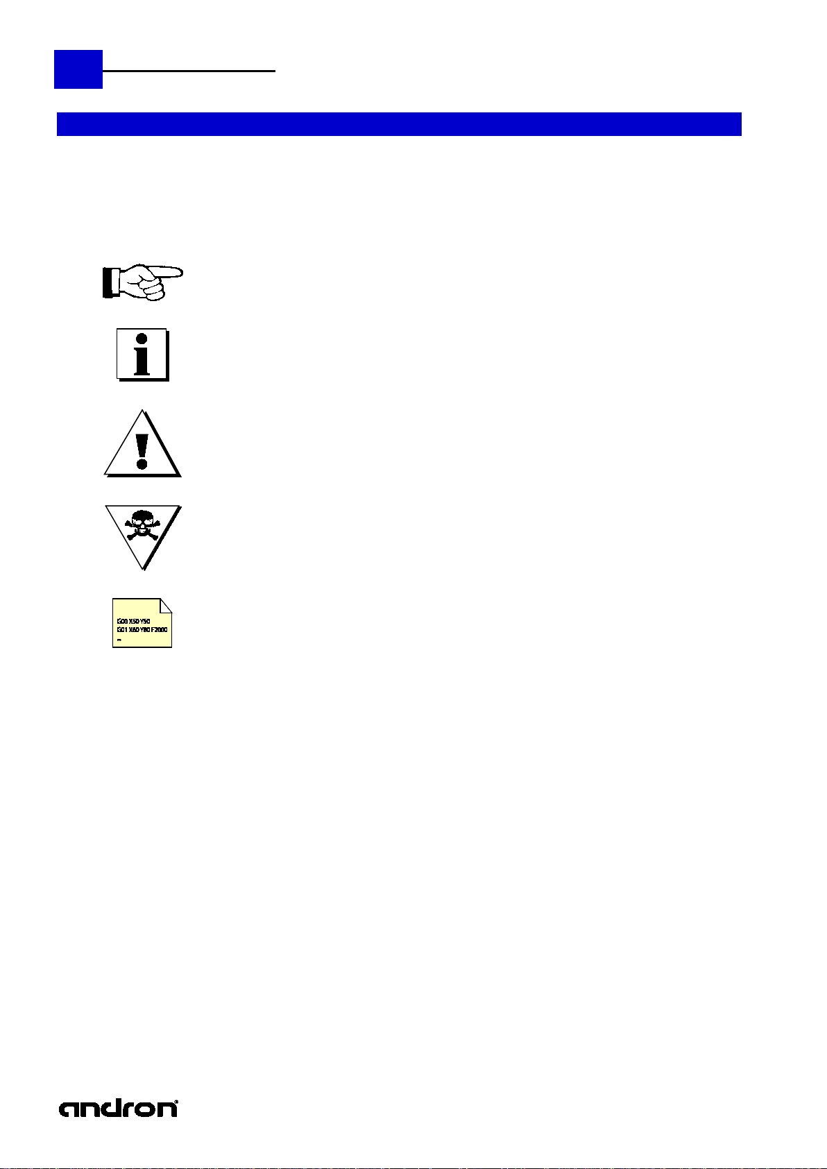
This description uses the following warnings and symbols:
Safety instructions
Warnings and symbols
This sign contains general and additional information or instructions
and prohibitions for avoiding damage.
Important information or cross references to other descriptions.
Warning on personal and machine damage, i.e., information or instructions and
prohibitions for avoiding personal and machine damage.
Caution Extremely Dangerous!!!
This symbol indicates an example.
gm_code_programming_manual_v6.05.08.02.doc
Page 9
andronic 2060/30 60
G&M Code Programming Manual
Introduction
andron products are developed and p roduced in accordance with current state-of-the-art m ethods.
In order to guarantee the designated use of the products, the following r equirements must be met,
Anyone handling one of our products in any way must have read and under stood the safety
Areas of application and use
The control unit is designed for incorporation i n a control panel, in the wall or door o f a switching
by specialized personnel.
Using the CNC control outside of the above-mentioned fields of application or under operational
extreme variations in temperature or extreme minimum temperatures.
Designated use
9
Before delivery, their safe operational status is verified.
The products may only be used in accordance with their designated use. Any use contrary to their
designated use may produce situations that result in personal damage or material damage.
As the manufacturer, andron will not give any warranty, will not be liable nor pay for
damages resulting from the use of the products contrary to their designated use. The
user shall bear all the risks of using the products contrary to their designated use.
before using the andron products:
instructions and the designated use.
If the products are hardware, they must be left in their original state, i.e., no constructional
changes may be made. Software products must not be decompiled, and their source codes must
not be changed.
Damaged or defective products may not be installed or put into operation.
Provisions must be made that the products are installed in accordance with the regulations given
in the documentation.
cabinet or directly in the enclosure of a mac hine tool. Make sure that the mounting, ins tallation and
environmental conditions are observed.
The designated use also requires the use of a soft- or firmwa re offered by andron for the control unit.
Each control system must be submitted prior to startup to suitable parameterization and programming
Use of the unit c o n t rary to its desi g nated use
conditions and technical data other than those described in the documentation is considered "contrary
to the designated use".
Serious injuries - Life-threatening injuries
The control unit may not be used if it is subject to operational conditions that do not meet the
prescribed environmental conditio ns. For example, it is prohibited to operate it underwater, under
gm_code_programming_manual_v6.05.08.02.doc
Page 10
10
andronic 2060/30 60
G&M Code Programming Manual
The sequence of a machining process on the machine is described by the NC program. It c onsists
Example
G02 X50 Y0 I25 J0 F2000 S10000 M3 T7 M6
G02
Path condition circle in clockwise direction
X50
X coordinate
Y0
Y coordinate
I25
Auxiliary parameter circle center X coordinate
J0
Auxiliary parameter circle center Y coordinate
F2000
Feed speed 2000 mm/min
S10000
Spindle speed 10000 1/min
M03
Machine function 'Spindle on'
M06
Machine function 'Change tool'
Special signs
%
The rest of the line is interpreted as a comment
;
The rest of the line is interpreted as a comment
[ ]
Jump mark, index at FlexProg
/*...*/
Encapsulated comment at FlexProg
( )
Comment, function bracket at FlexProg
Components of a NC program
mainly of a sequence of program r ecords. In a all the necessary information for a work step ar e
included. Record numbers can be entered under the address N.
With the andronic control, the programming is also permissible without block numbers.
With program words, as a general principle, a dif ferentiation is made betwe en modal ( latching) and
non-modal words. A word is modal if its value remains effective until it is overwritten by another
value, or the end of the program has been reached. In contrast, non-modal words only have an effect
within the block in which they have been programmed.
The following can be programmed within a block.
Character Function
N Block number (optional)
G Path condition
A Path information A axis
B Path information B axis
C Path information C axis
X Path information X axis, dwell time
Y Path information Y axis
Z Path information Z axis
I, J, K Interpolation parameters, circle center
F Feed speed, dwell time, time display at G95 (Invers Time Programming)
O Output address
D Auxiliary information (correction memory)
E Additional information on the PLC
S Spindle speed
T Tool number
M Machine function
Q Parameter programming
W Command extension
gm_code_programming_manual_v6.05.08.02.doc
Page 11

andronic 2060/30 60
G&M Code Programming Manual
• 100 tool magazine slots per tool magazine,
In the magazine assignment table, a duplo tool can be specified for every tool. This duplo tool is used
A cycle which blocks a tool cannot automatically load a duplo tool and continue the NC program. If
reaction to the problem can be adjusted using FlexProg.
Every tool type has an adjusted input screen. Some parameters are always required, others are
missing, the NC program is cancelled with an error message.
Obligatory parameters:
• Length
• Tool size
Optional parameters:
• Pages 1 and 2:
• Coolant control
Tool management
Functions of the tool management
• any number of tool magazines in the database,
• configurable tool types,
• 1 tool magazin, several pick-up places,
• several magazin assignment table files,
• variable or fixed coding of slots ,
• duplo tools,
• 3 different types of status indication,
• 9 tool dimensions per tool usable,
• tool life control with remaining tool life indication,
• limitation of maximum speed,
• tool dependent speed output,
• rotation direction control,
• coolant control,
• wear control (option),
• Numerous adaptation possibilities at the machine:
• chain or disk magazine, pick-up, manual change in any combination up to a total of 100
locations,
• correction of position for every single magazine location ,
• programming of the tool change procedures in G&M code format,
• Different options:
• tool can be changed, despite tool life has expired ,
• interruption of the NC program during speed reduction of the tool management,
• in case of tool magazine problems, all tools can be changed manually without
intervening within the tool management,
• Support of tool magazines with PLC- or sercos drive,
11
Duplo tools
Tool data
when changing the tool if the programmed tool is blocked. The duplo tool can have another duplo
tool. Thus, a chain can be determined by replaceme nt tools .
such behaviour is desired, the error reaction of the cycle can be adjusted using G782,0 E0 and the
optional. The tool data are checked only when the NC program runs. If obligatory parameters are
• Release by the operator
• Radius (in case of milling cutters)
• Allowance for length and radius
• Wear for length and radius
• Positive and negative tolerance of the radius
• Status for idle time and tool breakage
• Page 3:
• Service life data
• Nominal speed
• Maximum speed
• Speed direction control
gm_code_programming_manual_v6.05.08.02.doc
Page 12
12
andronic 2060/30 60
G&M Code Programming Manual
Tool dimensions:
• Length, allowance and wear are added by the control system and the result will be set as active
• Entry: upper and lower overall dimension.
TCP active:
• Information for RTCP function. Activate (1) if the 5-axis NC program for the ball centre
(Tool-Center-Point - TCP) has been calculated.
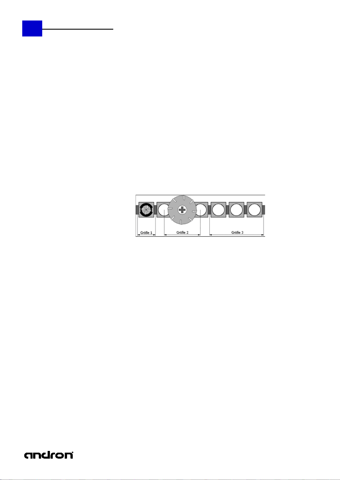
Tool size:
The size number stands for the number of half places occupied to one side.
out of its magazine place for half a place to each side).
Fixed-place coding:
This parameter permits the fixed-place coding of tools with the tool size 1 which are normally part of
maintain a fixed place in the magazine or a weight optimisation of heavy tools can be obtained.
Additional correction values:
Apart from the length and the radius of the tool, it is possible to call up from the NC program the
using D2 (or D0=2) to D9 (or D0=9).
Service life recording:
• In order to use the service life recording, a total service life must be entered in the respective
service life has been deleted, the total service life is valid again.
tool length when changing the tool.
The allowance is entered by the operator and is used for specifying an allowance on the
workpiece.
The wear is determined and entered by Blum cycles if wear de termination has been activated or
by load cell cycle "G189 load cell tool breakage control".
• Radius, allowance and wear are added by the control system and the result will be taken into
consideration during execution of the NC progra m .
The allowance is entered by the operator and is used for specifying an allowance on the
workpiece.
The wear is determined and entered by Blum cycles if wear determination has been activated.
• Radius dimension limit: tolerance limits monitoring. The total radius must be within the tolerance
limits.
• Program cancellation in case of unacceptable extent of wear.
• No specification of the radius tolerance means that radius tolerance will not be monitored.
(i.e. a tool of size 1 occupies two half places, consequently exactly one place; a tool of size 2 s ticks
a variable tool management. Thus, in case of variable place coding, for example a touch probe can
length and radius data for 8 further pairs of correction values. To this end, the NC address "D" or
"D0=" with the number of the desired pair of correction values is used. When calling up the tool, the
first pair of correction values will automatic ally become active if no other pair has been activated
tool file. After the first use of the tool by the machine, the status and the remaining service life
will automatically be entered in the tool data.
• If a prewarning limit has been entered, a message will appear in the position display as soon as
this limit has been reached.
• The remaining service life can be changed at any time.
• After expiry of the service life, the status of the tool will be set to the value " 0"-blocked- during
the next tool change and the tool will not be loaded again. If a dup lo tool is available, it will
automatically be used.
• The option "Use of tools beyond service life limit" can be activated in the magazine
configuration. In this case, the continuation of the machining process will be offered if no
released duplo tool is available.
• In order to reactivate a blocked tool, the service life status must be set to "1"-released- and the
remaining service life must be deleted or set to a value greater than zero. If the remaining
gm_code_programming_manual_v6.05.08.02.doc
Page 13

andronic 2060/30 60
13
G&M Code Programming Manual
Special functions:
•
Speed specification
: If a nominal speed is defined in the tool data, this value will be set as
be supported by the machine manufacturer.).
Measurement data:
• Entering the measurement data for the BLUM laser measuring cycles for tools measuring (see
entering the data for G387 "Cutter control on rounded cutting geom etry"
G382- Temperature
Address
Designation
Function in the Blum cycle
X
RTOL
Max. allowed zero-point correction in the X/Y axis in case of comparative
measurement
Z
LTOL
Max. permissible zero-point correction in the Z axis in case of
comparative measurement
G383- Tool length measurement
Address
Designation
Function in the Blum cycle
Z
LTOL
Permissible wear tolerance for tool length
G384 - Setting length and radius
Address
Designation
Function in the Blum cycle
D
CUT
Number of the tool cutters for the cutter control
H
R_MeP
Radial measuring position for length measurement (OL)
J
L_MeP
Axial measuring position for radius meas urement (OR)
O
RBREAK
Permissible concentricity tolerance during cutter control (TOL)
X
RTOL
Permissible wear tolerance for tool radius
Z
LTOL
Permissible wear tolerance for tool length
G385- Cutter control on straight
Address
Designation
Function in the Blum cycle
D
CUT
Number of the tool cutters for the cutter control
O
RBREAK
Permissible concentricity tolerance during cutter control (TOL)
G386 - Tool breakage control
Address
Designation
Function in the Blum cycle
H
R_MeP
Eccentric control position
Z
LTOL
Permissible length tolerance for tool breakag e detection (TOL)
G387- Cutter control on rounded
Address
Designation
Function in the Blum cycle
D
CUT
Number of the tool cutters for the cutter control
H
R_MeP
Radial offset to the starting point of the corner radius (O)
E
CR
Corner radius / cutter radius / ball head radius (CR)
I
TA [degree]
Starting angle Alpha to the symmetrical axis (a )
J
TB [degree]
Target angle Beta to the symmetrical axis (b)
Z
LTOL
Control way on the tool shank (W)
O
RBREAK
Permissible form tolerance during cutter control (TOL)
spindle speed during the tool change if no speed has bee n programmed in the NC block. The
speed specified in the tool data applies only to the respective tool. The output is carried out in
the main spindle mode 1 for spindle 0 and in the main spindle mode 2 for the selected spindle.
•
Maximum speed limitation
as spindle speed during the tool change if the speed programmed in the NC block is greater than
the maximum speed. In the tool management options, it is possible to define whether the NC
program will be interrupted with a message in case of a speed reduction or whether the speed
has to be reduced automatically.
Speed direction control
•
rotation which will be compared with the programmed direction during each spindle start in order
to prevent the use of a tool with wrong direction of rotation.
Coolant disabling
•
zero means: Coolant can be used for this tool. If "One" has been entered, the NC program will
compare each coolant request with the coolant disabling of the tool. If an unacceptable coolant
has been programmed, the NC program will be cancelled and an error message displayed.
•
Tool measuring:
description of the BLUM laser measuring cycles). When calling up the cycle, the tool-specific
measurement data are transferred to the cycle if they are NOT included in the NC program.
• When executing the Blum cycles, the parameters from the NC program have top priority. In the
NC program, not specified parameters are used from tool data and, if not available there either,
from the presettings of the cycle.
• The tool type corner radius milling cutter and die sinking cutter have an additional parameter for
: This function allows ce rtain coolants to be disabled for the tool. No entry or
This function activates tool measuring during tool change (This function must
: If a maximum speed is entered in the tool data, this value will be set
: The speed direction control serves to define for the tool a direction of
compensation of the NC axes
of centric tools
of the tool with concentricity
cutting geometry
cutting geometry
control
gm_code_programming_manual_v6.05.08.02.doc
Page 14
14
andronic 2060/30 60
G&M Code Programming Manual
The M functions initiate certai n machine func tions. These fu nctions may differ depending on machine
type/manufacturer.
M01
Optional stop
1
M02
End of program
1
M03
Spindle 0 On (clockwise)
2
M04
Spindle 0 On (anticlockwise)
2
M05
Spindle stop
1
M06
Tool change (active spindle)
2
M07
Coolant 1 On (not according to DIN 66 025)
2
M08
Coolant 2 On (not according to DIN 66 025)
2
M09
Coolant Off
M10
Clamping On
M11
Clamping Off
M12
Pallet change
2
4
M13
Spindle 0 On, clockwise rotation and coolant 1 On
2
M14
Spindle 0 On, counterclockwise rotation and coolant 1 On
2
M19
Spindle stop with defined end position; angular position at "S" in degrees
1
M30
End of program with spindle 0 Off
1
M50
Coolant 3 On
2
M51
Coolant 4 On
2
M67
Open collet
2
3 M68
Close collet
2
3
M69
Open tool gripper (variable pocket code)
2
3
M70
Close tool gripper (variable pocket code)
2
3 M99
End of program with neutral position approach
1
M100
Programmed stop with optional restart position
1
M103
Spindle 1 On clockwise
2
6
M104
Spindle 1 On anticlockwise
2
6 M105
Spindle 1 stop
1
6 M106
Tool change in spindle 1 (reserved M command)
2
6
M121
Unclamp pallet
2
4
M122
Clamp pallet
2
4 M123
Manual pallet change
2
4 M203
Spindle 2 On clockwise
2
6
M204
Spindle 2 On anticlockwise
2
6
M205
Spindle 2 stop
1
6 M206
Tool change in spindle 2 (reserved M command)
2
6 M303
Spindle 3 On clockwise
2
6
M304
Spindle 3 On anticlockwise
2
6
M305
Spindle 2 stop
2
6 M606
Manual tool change from tool magazine
2
3 M610
Read tool data from PLC
2
3
M611
Prepare tool magazine
2
3
M640
Start position log
2
5 M641
Stop position log
2
5
M Functions
M Function A.* A.*
M00 Programmed stop 1
1
2
2
gm_code_programming_manual_v6.05.08.02.doc
Page 15
andronic 2060/30 60
G&M Code Programming Manual
Different machine configurations require machine functionalities which can only be achieved in
collaboration with andron.
Spindle change from selected spindle to spindle 0
2
Spindle change to spindle 1
2
Spindle change to spindle 0
Spindle change to spindle 2
2
Spindle change to spindle 0
2
6
Spindle change to spindle 3
Spindle change to spindle 0
2
* Comments on the M commands:
1
Function is effective at end of block
2
Function is effective at start of block
3 freely definable in tool change configuration
4 freely definable in pallet management configuration
5 freely definable in position log configuration
6 reserved commands (optional)
Extensions of M comman d s (option)
M Function A.* A.*
Spindle change from 0 to selected spindle (PLC) 2 6
15
6
6
2 6
6
2 6
6
gm_code_programming_manual_v6.05.08.02.doc
Page 16

16
andronic 2060/30 60
G&M Code Programming Manual
Property:
MODAL means that the command/function remains active until it is
Topic:
The G functions can be divided into the following topics:
Position:
DEF = Default (active after starting the control unit)
--- = Not pre-set
G Functions
Explanations
overwritten.
Interpolation type
special command
setup command
tool command
cycle command
gm_code_programming_manual_v6.05.08.02.doc
Page 17
andronic 2060/30 60
G&M Code Programming Manual
Property
modal
Topic
Axis movement
Position
---
Syntax
G00
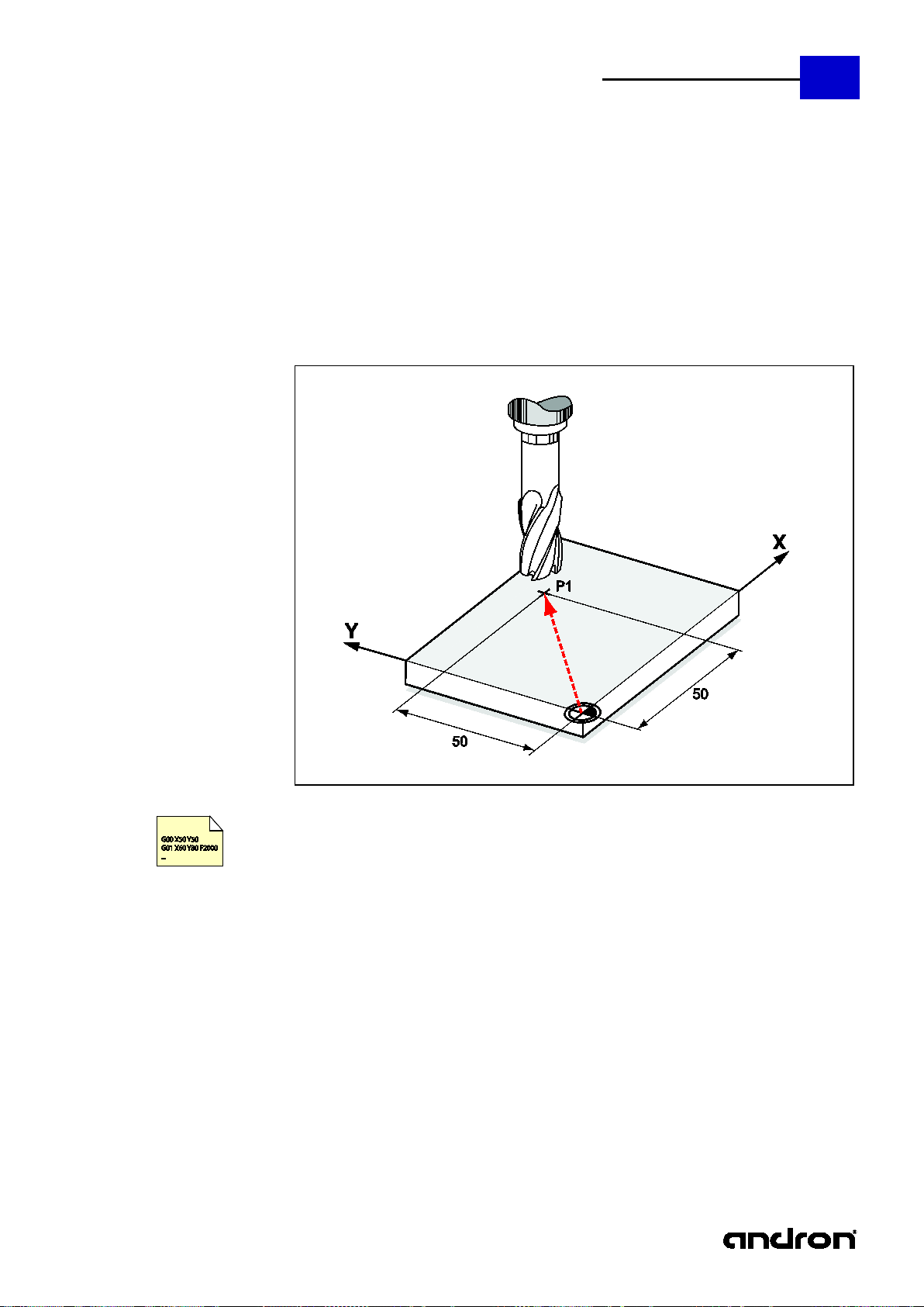
The path information G00 programs rapid traver se movements by specifying the target point. The
sions. The rapid traverse
G00 X50 Y50 ; The axes are moved by interpolation to point P1
G00 Positioning in rapid traver se
target point is reached by enter ing it either in absolute or relative dimen
speed can be defined in the EEPROM.
17
gm_code_programming_manual_v6.05.08.02.doc
Page 18
18
andronic 2060/30 60
G&M Code Programming Manual
Property
modal
Topic
Axis movement
Position
DEF
Syntax
G01
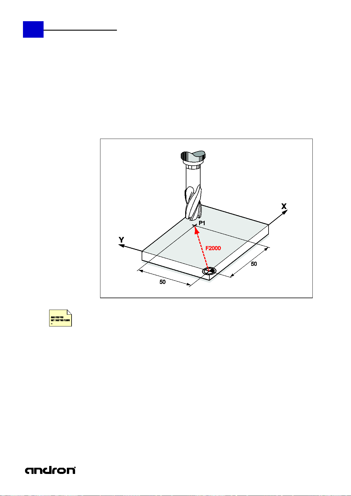
The path information G01 programs feed movements by sp ecifying the target poi nt. The target point
G01 X50 Y50 F2000 ; Positioning at point P1 at 2000 mm/min
G01 Positioning at the feed rate
is reached by entering it either in absolute measure or relative measure. The feed rate c an be defined
in the EEPROM or programmed by means of the F parameter.
gm_code_programming_manual_v6.05.08.02.doc
Page 19
andronic 2060/30 60
G&M Code Programming Manual
Property
modal
Topic
Axis movement
Position
--- Syntax
G02 /G03 <Parameter list>
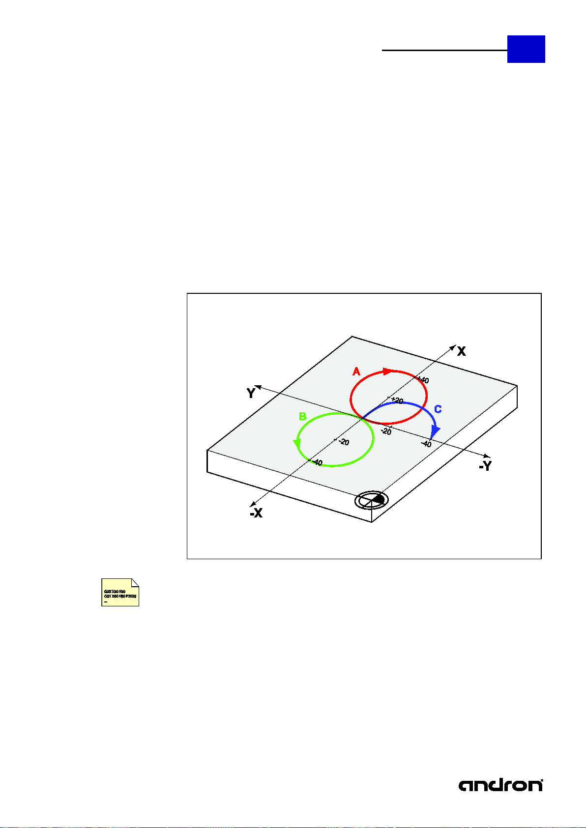
For the circular interpolation, th e axes are moved on an arc from the starting po int to the end po int.
G01 X0 Y0 ; Starting point approach
G02 X0 Y-40 R20 ; Clockwis e travel to X0 Y-40. Radius 20 mm (C)
G02 Circular interpola ti on - Clockwise
G03 Circular interpola ti on - Counterclockwise
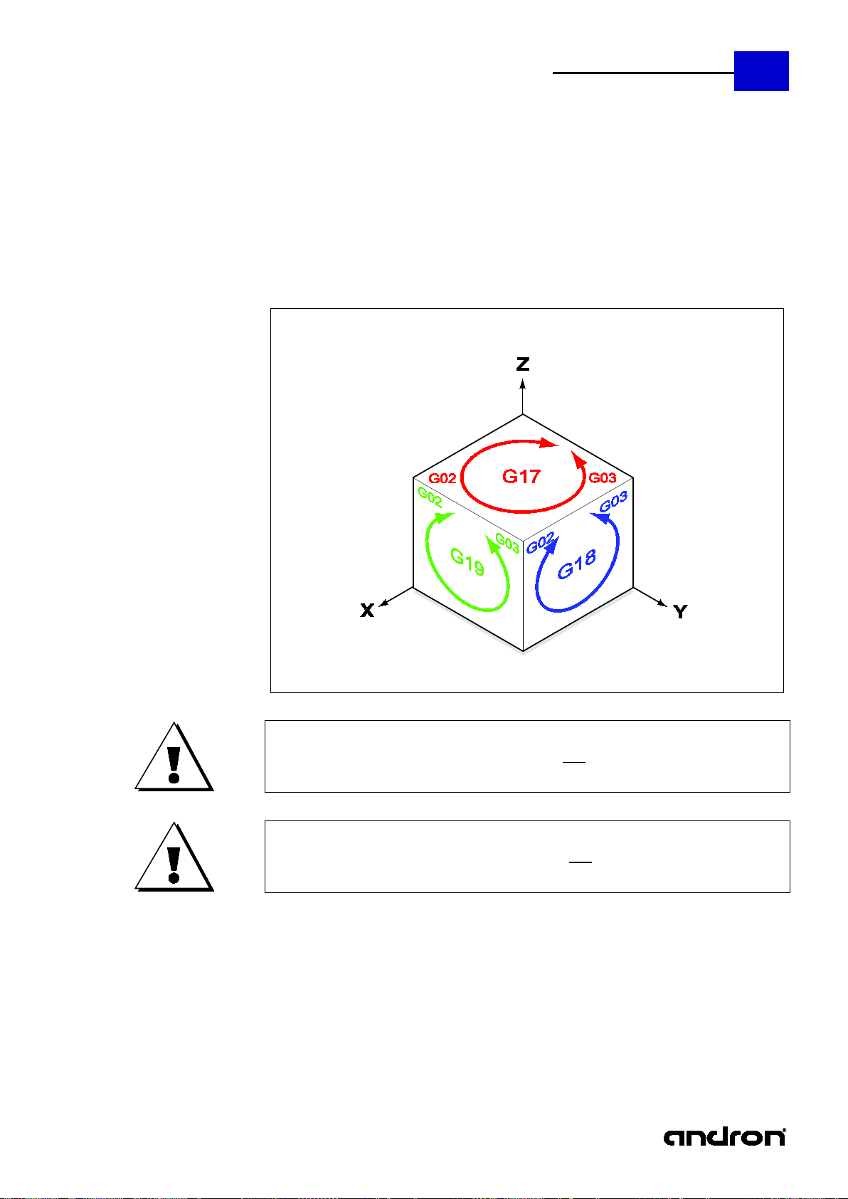
The movement can take place clockwis e by selecting G03 and counterclockwise by selecting G03.
Circular interpolation must contai n the following parameters and can b e applied in all 3 planes (see
G17 - G18):
G02 or G03 (direction of rotation), end point of the arc, radius of the cir cle (R) or circle c enter (I, J,
K) The center of the arc can be sp ecified in absolute (G190) or relative (G191 ) coordinates. As an
alternative to the center, the arc rad ius can be pr ogrammed directly by entering the address letter R .
However, this only applies to arcs having an angle of rotation of less than 180°.
19
G02 X0 Y0 I20 J0 ; Clockwise travel to X0 Y0. Circle center at X20 Y0 (A)
G03 X0 Y0 I-20 J0 ; Counterclockwise travel to X0 Y0. Circle center at X-20 Y0 (B)
gm_code_programming_manual_v6.05.08.02.doc
Page 20
20
andronic 2060/30 60
G&M Code Programming Manual
Property
modal
Topic
Axis movement
Position
---
Syntax
G04 <Parameter list>
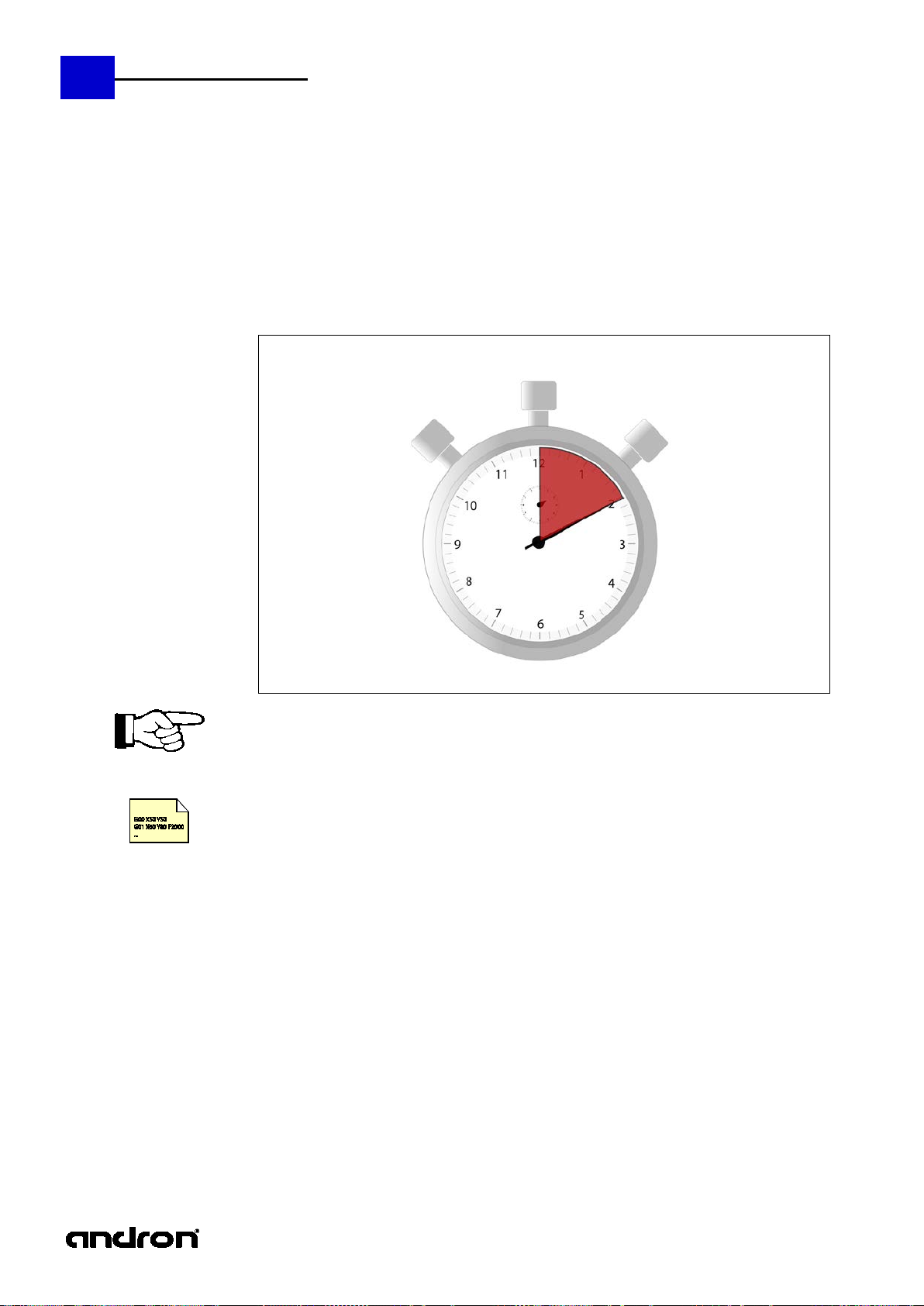
The function G04 allows you to pr ogram a dwell time. The time is sp ecified by the parameter X. The
G04 without parameters is used for interruption of the contour, without any further action to
G04 X11.4 ; Dwell time 11.4 seconds
G04 Dwell time
function is only effective blockwise. The maximum prog rammable dwell time is 655 seconds.
synchronize of read data, LookAhead and position, and the exact position setting of calculation results
or variables.
gm_code_programming_manual_v6.05.08.02.doc
Page 21
andronic 2060/30 60
G&M Code Programming Manual
Property
modal
Topic
Axis movement
Position
---
Syntax
G05 <Parameter list>
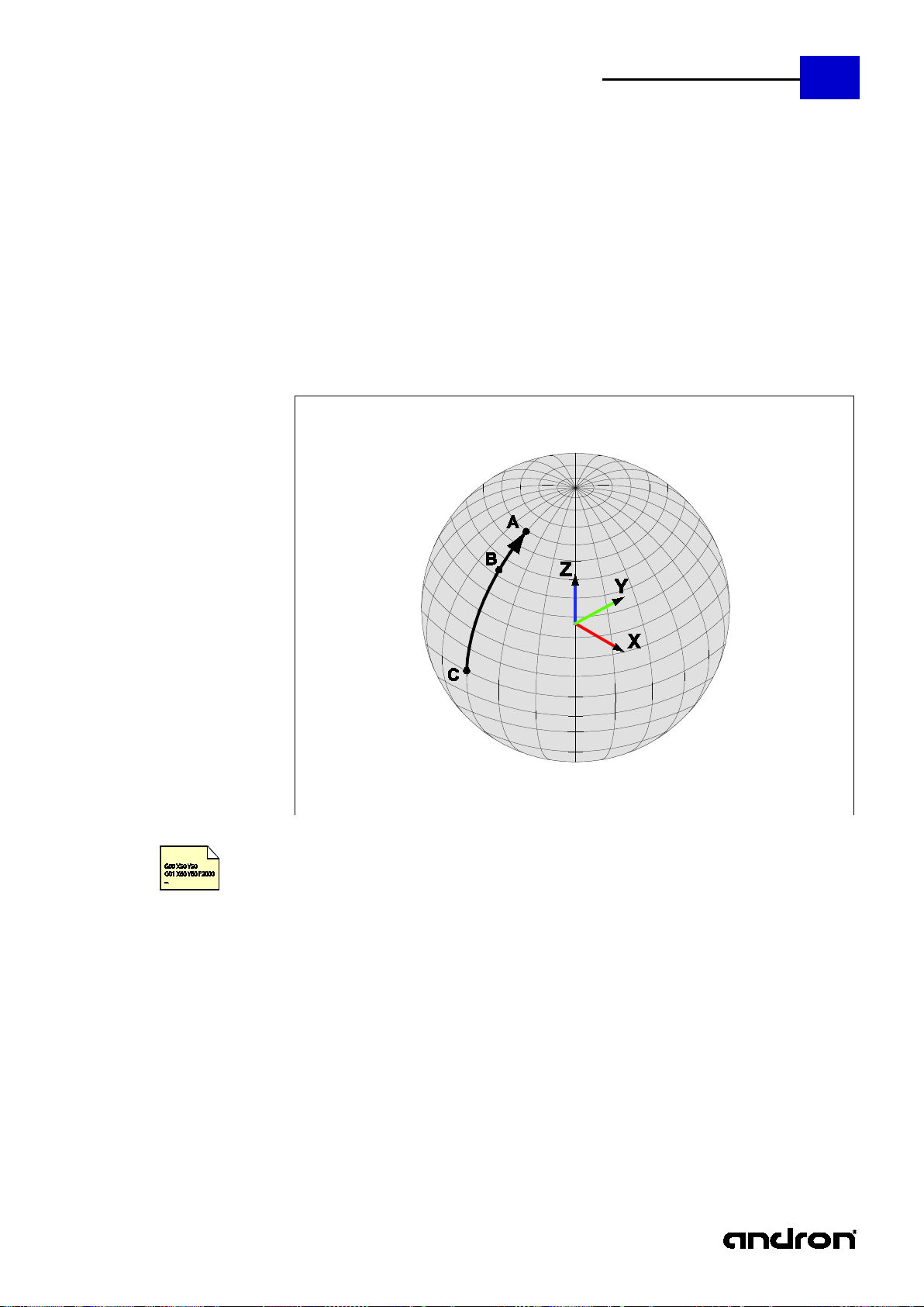
This function allows you to describe a spatial arc (spatial circle section). No information such as radius
G01 X0 Y0 Z0 ; Starting point approach
; Intermediate point at X20 Y30 Z30
G05 Spatial arc interpolation
or direction of rotation exists for this function. The interpola tion parameters work in the same way as
G02 / G03.
An G&M code for spatial arc interpolation must contain the following parameters:
G05, end point of the spatial arc in X, Y and Z (A), intermediate point on the spatial arc in I, J and K
(B). The starting point (C) of the spatial arc is determined by the current axis position.
21
G05 X50 Y50 Z0 I20 J30 K30 ; End point at X50 Y50 Z0
gm_code_programming_manual_v6.05.08.02.doc
Page 22
22
andronic 2060/30 60
G&M Code Programming Manual
Property
non-modal
Topic
Special command
Position
---
Syntax
G14 N = [“] Macro name [“] [Pn]
A macro is a closed program part that must be progr ammed only on ce. A ma cro is not exec uted until
it is defined or called by the main program or another macro. In contrast to the genuine
#Rectangle# ; Header containing the name of the macro
## ; End identifier
The optional inverted comma cha racters [“] at the beginning and end of the name only have to be
by a number, indicates how many times the macro is to be executed. The maximum number of
G14 N = Rectangle P3 ; Example macro called three times
G14 Macro call
subprograms, macros are incorporated in the program text. A macro starts with a heade r in which the
name of the macro is defined. No other instructions (not even block numbers) may be programmed in
the header. The name of the macro mus t not contain more than 24 characters and stands between
the character #. The end of the macro definition is marked by a bloc k containing the instructi on ##.
Here, too, no other instructions may be programmed.
G01 X0 Y0 F2000 ; Instructions
X100
Y100
X0
Y0
entered if the name of the macro contains symbols or blan ks. The o p tional addres s lett er 'P', fo llowed
repetitions is: 32
Prior to compiler version V5.3R3: 32 repetitions maximum
From compiler version V5.3R3: 256 repetitions maximum
If a macro has been defined as described above, it can be called in the program as follows.
gm_code_programming_manual_v6.05.08.02.doc
Page 23
andronic 2060/30 60
G&M Code Programming Manual
Property
modal
Topic
Setup command
Position
Preset G17
Syntax
G17 / G18 / G19
G17 Plane XY
G18 Plane ZX
G19 Plane YZ
23
A change of plane via G17/G18/G19 does not cancel active zero offsets.
A change of plane with G17/G18/G 19 d o es not cancel an active rotation.
gm_code_programming_manual_v6.05.08.02.doc
Page 24
24
andronic 2060/30 60
G&M Code Programming Manual
Property
non-modal
Topic
Special command
Position
---
Syntax
G22 N = [“] Program name [“] [Pn]
G22 N = [“] Database path: Program name [“] [Pn]
Programs that must be repeated several times can be called from a main program by entering G22.
This program is available as a separate NC program in the same database as the calling main
icates how many times the
G22 N = Feed program P3 ; Feed program called three times
G22 Sub program call
program. If the prog ram to be called is not included in the program database of the control, the
database path must also be specified. Enter the designation fr om "Programs / da ta base:" to call the
database path in the Xpanel.
Example:
G22 n="C01:ncprg_name" is loading from the user database path 1
G22 n="S05: ncprg_name" is loading from the system database path 5
The program name may contain 24 characters maximum. The optional inverted comma characters [“]
at the beginning and end of the name only ha ve to be e ntered i f th e progr am name contains symbo ls
or blanks. The optional address letter 'P', followed by a number, ind
program is to be executed. The maximum number of repetitions is: 32534
gm_code_programming_manual_v6.05.08.02.doc
Page 25
andronic 2060/30 60
G&M Code Programming Manual
Property
non-modal
Topic
NC command
Position
---
Syntax
G23 N = “Text “ P<Type> I<Index>
The command G23 can be used to call up different func tions with AS CI I texts. The tar get is alw ays to
transmit a text with a length of 80 character s to the PLC, CNC or the display.
Type - P
Command
Index - I
0 - Default
Transfer text to the PLC
not necessary
1 ASCII variables of the CNC - is not supporte d at the moment
-
2 ASCII parameter of the CNC - is not supported at the moment
-
3 Transfer text to the XPanel user interface
1-3
Default (1)
4 Redefines the measuring log file names of the measuring cycles
start.
not necessary
5 Writes the values of the communication variables into a log file.
(This data is not transmitted during the block search)
IKV index
G23 N=“Drill 3mm“
Text is transmitted to the PLC
G23 P3 N=“Finishing part1“ P3
Text is displayed in the prompt of the XPanel position
G23 P3 N=“ Finishing part1“ P3 I1
Text is displayed in the prompt of the XPanel position
G23 P3 N=“ Finishing outside“ P3 I2
Text is displayed in the prompt of the XPanel position
G23 P4 N=“C:\Messung_123.log“
Beginning with this program line, the measuring cycles
IKV[100] = 1.456
G23 P5 N=“C:\Daten_123.log“ I100
The value of IKV[100] is written into the log file
"C:\Daten_123.log".
G23 Text - Functions
25
"mprot.log". If no path is specified, the data are transmitted to
%andronroot%\System\ (C:\Andron\System\*). Specified paths
are not created by the CNC and must already exist at program
The transmission to the PLC must be prepared in the PLC program.
See NcSatz_Konfiguratio n.chm
G23 P0 N=“ Drill 3mm“
menue in line 1.
menue in line 1.
menue in line 2.
of the log file will be named with the specified
designation and the path specification and no longer
with "C:\Andron\mprot.log".
gm_code_programming_manual_v6.05.08.02.doc
Page 26
26
andronic 2060/30 60
G&M Code Programming Manual
Property
modal
Topic
Special command
Position
---
Syntax
G25 <Parameter list>
RTCP describes the functionality of keeping a (TCP - Tool Center Point) constant during the
program but the
RTCP is activated according to the kinematics of the machine
defined in the machine parameters.
The state of RTCP (ON/OFF) is stored in the buffer, e.g. to
The state of RTCP (ON/OFF) stored in the buffer is restored,
sets
G25 RTCP H On/Off
movement of rotatory axes. Despite the use of rotatory axes, the pos ition of the TCP relative to the
workpiece does not change. RT CP normally effects a of the corr esponding axes if one of the rotary
axes is moved.
RTCP can be switched on/ off with the H para meter to G 25. The storing and restoring of RTCP s tates
is administered specifically to the program, i.e. if RTCP is deactivated in the substate RTCP active was stored in the main program, the state RTCP is actively restored after returning
from the sub-program and the RTCP command.
G command Designation Meaning
G25 H0 Switch off RTCP RTCP is deactivated
G25 H1 Switch on RTCP
G25 H2 Save RTCP state
G25 H3 Restore RTCP state
be used with tool change NC sets
e.g. with a temporary deactivation in the tool change NC
gm_code_programming_manual_v6.05.08.02.doc
Page 27
andronic 2060/30 60
27
G&M Code Programming Manual
Functional descri pti on
Axis traverse movement in
direction
The use of axis traverse movement in milling lengthwis e axis direction is possible by defining the
Activation/deactivation must be realised by adaptations in the PLC software:
Selection of traverse movement in milling lengthwise axis direction via this key on the machine
operating panel in manual mode (not MDI, not AUTOMATIC interr uption!).
The traverse movement is carried out by p ress ing the tra verse move ment keys in posit ive or negati ve
the tool tip and a positive traverse path is preset by a movement to the tool shank.
Moving in the milling lengthwise axis direc tion is not possible in the automatic mode.
Activation and deactivation of
5-axis transformation
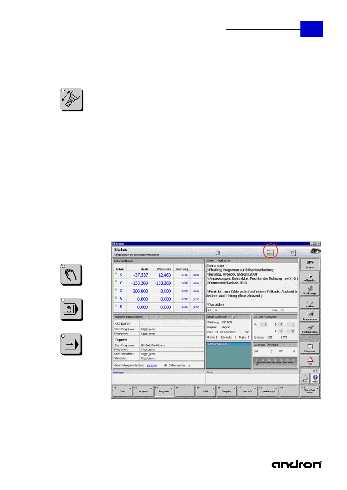
The status of the transfor mation is dis played in the status area in t he top right cor ner on the XPanel
with the text "G25 RTCP” on an icon.
Activation in the manual mode is possible by pre ssing the corresponding key. Activation in the MDI
and automatic mode is also possible by enter ing G25 H1.
In the position display, the p osition in the programm ing coordinate system ( PROG system) is a lways
depending on the position of the rotatory axes.
G25 H1
G25 H0
RTCP can be activated and deactivated as often as required within an NC block program.
Behaviour upon NC RESET
If RTCP is active, it also remains active after an NC RESET.
milling lengthwise axis
cinematic models regardless of an activated transformation.
1. On/Off button
2. LED ON for active / LED OFF for inactive
3. Flashing LED for invalid selection or selection not acknowledged by the CNC
direction (+/- and selection of the c orresponding fixed path 1mm, 0.1 mm, 0.01mm, 0.001mm or free
movement via the +/- keys or the handwheel). A negat ive traverse path is preset by a mov ement to
shown on the display of the control positi ons. Upon activa tion or deac tivation, the coordi nates move
gm_code_programming_manual_v6.05.08.02.doc
Page 28
28
andronic 2060/30 60
G&M Code Programming Manual
EMERGENCY STOP by
programs
RTCP is not reset automatically.
EMERGENCY STOP due to
drive error
RTCP is not reset automatically.
Referencing all axes or one
axis
RTCP is not reset automatically.
Tool change with RTCP active
G25 H2:
at the same time.
G25 H3:
After tool change, the previous status of the RTCP func tion in the tool change program is restored.
Changing axis settings in
The axis setting can be changed manually in the automa tic interruption mode and the program can
maintained. The changed setting is retained until the next rotary axis positioning takes p lace.
Moving axes in MDI with
RTCP active
All axes may be moved in MDI. There is no restriction as a function of the RTCP function.
G72/G73
Mirroring and RTCP
The G73 command makes it possible to acti vate the mirroring around the X or Y axis or a lso both
axes (prior to the activation of RTCP).
Programmed feed F
The programmed feed with active RTCP always refers to the resulting path of all programmed axes.
G288,1:
RTCP, the Time Basis Axis Programming command must be used.
G288,1 X1 Y1 Z1
It is thus possible to move one single axis faster than it was programmed. This is, for example,
Then the programmed feed affects the tool tip. However, the axis limitations with regard to
acceleration and speed are still active.
The command is cancelled by: (See LookAhead)
G288,1 X1 Y1 Z1 A1 C1 (B1)
Block search
During block search, the change-over of the RTCP switching state is only managed internally. When
setting down the tool, the last programmed state will be restored.
operator, PLC, control
RTCP must be deactivated in the tool change program. The status of the function (on or off) is saved
RTCP
be continued. The speed control is, however, optimised with regard to the previous axis setting and is
To ensure that the programmed feed only affects the X, Y and Z axes during five-axis operation with
necessary if important compensation movements of the translatory axes are required due to
movements of the rotatory axes.
The tool is set down in a configurable order. For large angular positions, we therefore
recommend positioning the rotatory axes in the manual mode.
gm_code_programming_manual_v6.05.08.02.doc
Page 29
andronic 2060/30 60
G&M Code Programming Manual
Property
modal
Topic
Setup command
Position
---
Syntax
G26 <Parameter list>
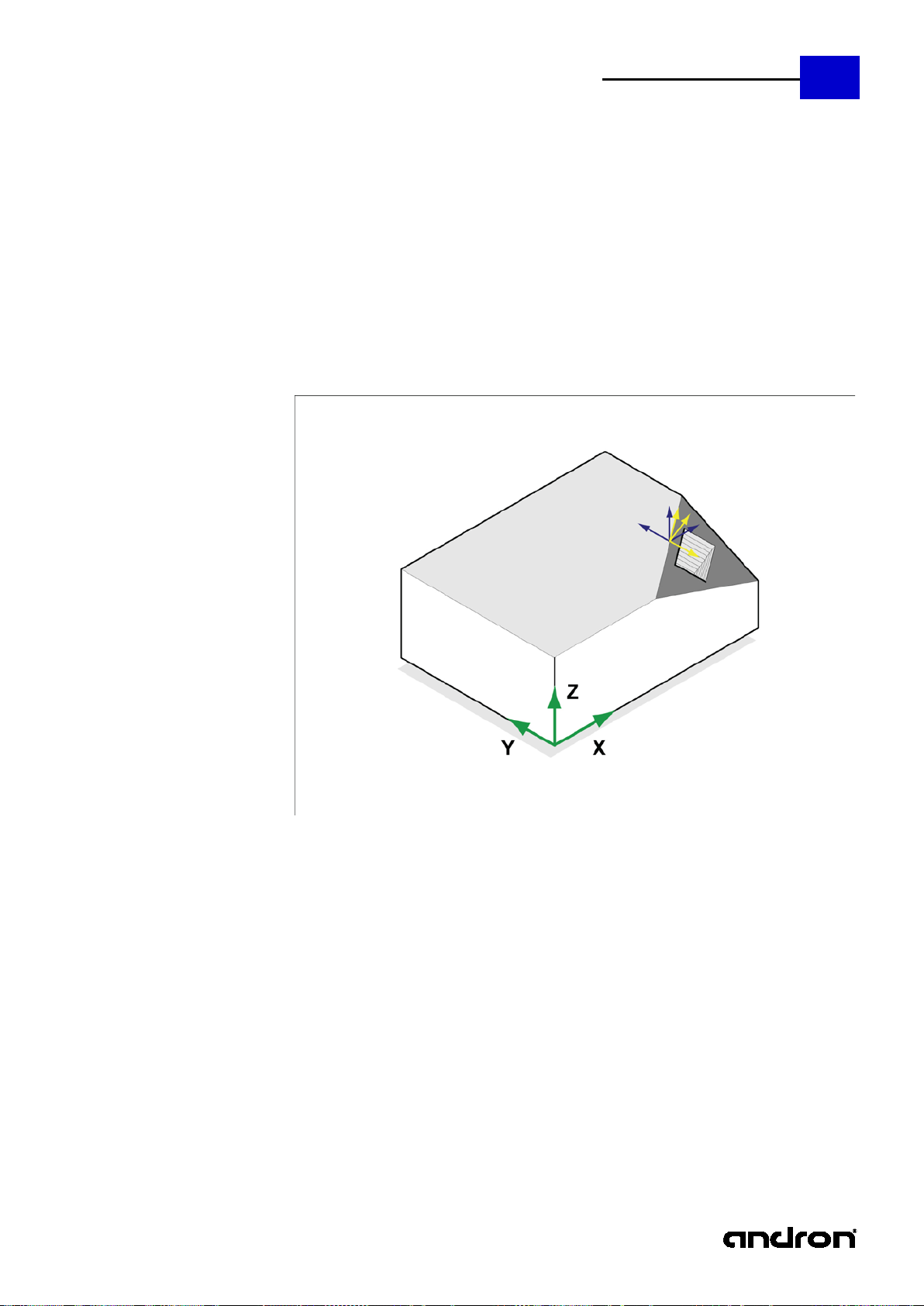
The command is used for defining the rotation of the programmin g coordinate system. It effects a
G26 Free plane
29
rotation around the specified an gles in the given order, the center of rotation is the current zero
point. The aim is the definition of a new machining plane which must not obligatorily be par allel to
one of the main planes. No movement takes place afte r specification of G26. But the display of the
current control position changes to the position with reference to the new system. After the command
was entered the changed coordinate system immediately becomes effective.
gm_code_programming_manual_v6.05.08.02.doc
Page 30
30
andronic 2060/30 60
G&M Code Programming Manual
Switch H is used to define the application of rotation WX, WY and WZ. If H
is not specified, H0 is applied.
The rotations are defined by means of Euler angle resp. solid angle. The angles are
specified. The specification of WX and WY is normally sufficient.
The angular positions are to be applied in a given order, which is specified with I, J,
WZ - Rotation around the Z axis
The defined angles define rotations in the stationary machine coordinate system. The
WZ - Rotation around the existing Z axis
The parameter R can be used to control whether the defined rotation shall take place
all angle variants of H.
These parameters contain the angl es to be set. Parameter H controls how to
determine these angles to reach the new position.
Order of the rotations with H1 where the following ap plies:
For H0 and H2 it is not necessary to specify an order.
Parameters Description
H
defined as follows:
H0
H1
H2
WX - Rotation around the current Z axis
WY - Turning around the new Y axis
WX - Rotation around the new Z axis
The rotations are always executed in this order, I, J and K must not necessarily be
and K. As a default the following order applies: I1 J2 K3 . Independent from the
programmed order, the angles are specified as follows with reference to the machine
coordinate system:
WX - Rotation around the X axis
WY - Rotation around the Y axis
order is therefore not to be specified. An angle defined with WX rotates the coordinate
system around the not-turned X axis of the machine system, no matter if other
rotations already apply.
WX - Rotation around the existing X axis
WY - Rotation around the existing Y axis
R
R1 new rotation is relative to the current coordinate system
R0 new rotation applies in reference to the machine coordinate system
WX, WY, WZ
I, J, K
Since G26 belongs to the group of commands for change of plane, the free plane is
deactivated for G17, G18 and G19. Since G26 allows rotations by 90° and more, a
with reference to the stationary machine axes or sha ll be rotated relative to the
current, already turned system. If R is not specified, R0 is applied. R can be used with
I is the position of the rotation WX around the X axis
J is the position of the rotation WY around the Y axis
K is the position of the rotation WZ around the Z axis
If no order is specified, the following applie s: I1 J2 K3.
If an order is specified for the rotation, all the defined angle s must be programmed
with an information regarding the order.
combination with the main planes is not necessary.
gm_code_programming_manual_v6.05.08.02.doc
Page 31

andronic 2060/30 60
31
G&M Code Programming Manual
Pocket milling on non-parallel planes, kinematics swivel head/rotary table
... ; Tool selection, technological data
Example of order G26 H1 WZ=-45 WY=30 K1 J2
Example of cancelation G26
cuboid workpiece with pocket geometry on inclined plane
point X70 Y30 Z50 is the marginal point of the new machining plane
the pocket has the sizes 35x20x25 [mm]
blue coordinate system is created by movement with G92
G26 rotates and swivels the system into the new position, the yellow coordinate system and the
searched machining plane (dark-gray) is created
G53 ; delete all zero offsets
G56 ; Workpiece zero with coordinate system parallel to
; the machine coordinates system (light-green)
G92 X70 Y30 Z50 ; Zero offset to the workpiece (blue)
G26 H1 WZ=-45 WY=30 K1 J2 ; rotation of the system first around the Z axis
; (WZ=-45 K1), then swiveling of the system
; around the new Y axis (WY=30 J2) - the new
; programming coordinate system (yellow)
; is created
;G26 WZ=-45 WY=30 ; same command by using Euler resp. solid angles,
; easy application, here as a comment
G25 H1 ; activate RTCP
G0 C45 B30 ; swivel
G87,1 B2 Z25 K5 X35 Y20 R4 J1 I40 D0 E250 ; Cycle definition in standard coordinates
G79 X15 Y0 Z0 ; Executive instruction
G26 ; Cancelation of the plane definition, G56 and G92
; is active again
G53 ; Cancelation of the absolu te a nd relative
; zero offset
G56 ; Activation of the workpiece zero
... ;
Example of Euler G26 WX=-45 WY=30
gm_code_programming_manual_v6.05.08.02.doc
Page 32

32
andronic 2060/30 60
G&M Code Programming Manual
Property
modal
Topic
Transformation command
Position
---
Syntax
G29 < Parameter list >
This command is used to parameterise the axis transformation and to switch it on and off. The
The cancellation of the transformation is carried out w ith G29 without parameters.
Cylinder body interpolation, direct
cylinder radius
Direct entry of the address of
the axis of rotation, value 1
Direct entry of the axis of
number
Cylinder radius
mandatory
parameter
Direction of the axis of rotation
optionally,
default 1
Cylinder body interpolation, indirect
cylinder radius
Direct entry of the address of
the axis of rotation, value 1
Indirect entry of the axis of
number
Direct entry of the address of
the translational axis, value 2
Indirect entry of the
Cylinder radius
mandatory
parameter
Direction of the axis of rotation
( 1 / -1 / default 1 )
optionally,
default 1
G29 Axis transformation
parameters define the axes involved and further parameters for the conversion of the programmed
into the transformed position. After sw itching on, the axis transformation is available in the manual
mode and in MDI. It is activated by means of an NC command in the automatic or in the MDI mode.
Absolute zero points of the rota ting axes are specified in degrees, relative offsets c an be indicated in
degrees but also in mm/inch.
The axis transformation cannot be combined with other transformations, for ex. RTCP.
Parameter Description Range of validity
H Type of axis transformation 1, 2, ...
H1
H2
programming and display of the axis of
rotation in mm and specification of the
A1, X1, ...
or Nxx
Rxx
J
programming of the axis of rotation of a
simulated axis in mm and specification of the
A1, X1,...
or Nxx
A2, X2,...
or Lxx
Rxx.x
rotation by means of the axis
rotation by means of the axis
translational axis by means of
the axis number
X, Y, Z, A, B, C
0-15
mm/inch
1 / -1
X, Y, Z, A, B, C
0-15
X, Y, Z, A, B, C
0-15
mm/inch
mandatory
parameter,
address or N
mandatory
parameter,
address or N
mandatory
parameter,
address or L
J
gm_code_programming_manual_v6.05.08.02.doc
1 / -1
Page 33

andronic 2060/30 60
33
G&M Code Programming Manual
H1
Switches the cylinder body interpolation on, the A axis is then programmed in
G29 H1 N0 J-1 R5.2 (entry via the axis number)
H2
Switches the cylinder body interpolation on, calc ula tion of the A axis from the
G29 H2 N0 L3 J-1 R5.2 (entry via the axis numbers)
If H1 is used, the NC position of the rotational axis is displayed in the programmed mm/inch, for
mm/inch:
G29 H1 A1 J-1 R5.2 (entry via the NC address)
mm/inch position of Y:
G29 H2 A1 Y2 J-1 R5.2 (entry via the NC add resses)
H2 in the calculated degrees.
For cylinder body interpolations for which the indirect position (H2) is specified, no position data
must be entered for the rotational axis after activation since it is calculated from the specification
of the 2nd axis (L).
The specification of J facilitates the change of the positive axis direction, for example, for
workpiece carrying axes.
When using circles, cycles and 2D milling cutter radius correction, it is often useful to specify a
programmable interpolation plane with G16.
For H2 it must be observed that the second axis also approaches the programmed position, the
use as simulated axis, for example U or V, is therefore often recommended.
gm_code_programming_manual_v6.05.08.02.doc
Page 34

34
andronic 2060/30 60
G&M Code Programming Manual
Property
modal
Topic
Traverse command
Position
---
Syntax
G30 <Axis information> oder <Spline head data>
{
Axis information
Possible axis information: A B C X Y Z
Spline head data
Axis identifiers of the axes involved (A, X, Z, Y, B, C, U, V) in control sequence
pos
Position of an axis
ric
Direction part (directional component) of an axis, not necessarily standardized
path
Approximated curve length in mm (convention: In the calculation of the curve or
Fvalue
Optional indication of speed in mm/min related to the resulting path in the
interval.
A X Z Y ; axis identifier without direction of start component (axis information)
G30 Spline interface (online spline)
pos, pos, [pos, ...,] ric, ric, [ric,...,] path [,Fvalue]
pos, pos, [pos, ...,] ric, ric, [ric,...,] path [,Fvalue]
...
pos, pos, [pos, ...,] ric, ric, [ric,...,] path [,Fvalue]
}
To make the analysis of the created NC set with spline effic ient and fast, the spline data are reduced
to an introductory path condition G30 with spline head data and a block matrix.
The converter recognizes fr om this the start situati on (cf. path starting poin t up to now) and trea ts
this accordingly. First spline arch p oint is implicitly the position which has been reached until th en.
Start direction in the first spline arch point is the d irection vector arising due to the Euclid distance
calculation. I.e. the direction vect or betwee n the current p osition a nd the firs t en try of the spline arch
points. This needs to be taken into account in the calculation of the first arch length (resulting path)
in the start interval within the pro gra m to be created (e.g. M as ter ca m) . Within the s pline head da ta it
is possible to also optionally declare the direction of start at the starting point of the spline.
The following parameters are used for definition:
The axis information defines the axis allocations and the orde r of the
subsequently expected positions and direc tions. At least two must be and a
maximum of 6 axis indications can be available.
with optional start direction [ric]. Between the axis information and/or the start
direction components there is no delimiter (spac e or comma) necessary. If start
direction components are used, the NC converter expects a directional
component for every axis identifier. The directional components are not
necessarily standardized.
arch length, mm is set to be the same as degrees and either all axes
should/have to be involved or a 'fictive path' that contains the speed profile
should/have to be indicated.)
A0.7 X1.0 Z0.33 Y0.1 C0.0 ; axis identifier with direction of start component (spline head data)
gm_code_programming_manual_v6.05.08.02.doc
Page 35

andronic 2060/30 60
G&M Code Programming Manual
Property
modal
Topic
Traverse command
Position
---
Syntax
G305 < Axis information >
{
Axis information
Possible axis information: A B C X Y Z, A6= ...
Spline head data
Axis identifiers of the axes involved (A, X, Z, Y, B, C, U, V) in control sequence
pos
Position of an axis
ric
Direction part of an axis (first derivative of the axis polynomial (path), scaled to
d2
First derivative of the axis polynomial (path), scaled to the arc length (path).
path
Path of the virtual lead axis in mm.
Fvalue
Optional indication of speed in mm/min related to the resulting path.
That means that the virtual lead axis Path is moved at the speed Fvalue.
A X Z Y ;a xis identifier
G305 P5-Interpolation (Online Polynomial)
pos, pos, [pos, ...,] ric, ric, [ric,...,] , d2, d2, [d2,...,] path [,Fvalue]
pos, pos, [pos, ...,] ric, ric, [ric,...,] , d2, d2, [d2,...,] path [,Fvalue]
...
pos, pos, [pos, ...,] ric, ric, [ric,...,] , d2, d2, [d2,...,] path [,Fvalue]
}
To make the analysis of the created NC s et with polynomials efficient and fast, the polynomial data
are reduced to an introductory path condition G305 with polynomial head data and a block matrix.
From this, the converter generates a G01 for the first point (first bloc k line after { ... }. The firs t spine
arch point is the position reac hed during this procedure. The first and the second derivative in this
first point of the polynomial is also taken from the data of the first block entry line.
The following parameters are used for definition:
35
The axis information defines the axis allocations and the orde r of the
subsequently expected positions and directions. At least two must be and a
maximum of 6 axis indications can be available.
the arc length (path).
Convention: In the computation of curves or arc length, mm is equated to
degree and either all axes should/must participate or a ”fictive path" including
the speed profile is to be indicated.
The path must not be smaller than the Euclidian distance of the points.
gm_code_programming_manual_v6.05.08.02.doc
Page 36

36
andronic 2060/30 60
G&M Code Programming Manual
Property
modal
Topic
Traverse command
Position
---
Syntax
G31 <Axis information> N<Number> F<Vmax> (max. 8 axes, contour number + Vmax)
G32 A<ric> X<ric> Y <r ic> (spline start with s tart direction vector)
G33 A<pos> X<pos> Y<p os>... [F<Vact>] (1. spline point)
G33 A<pos> X<pos> Y<p os>... [F<Vact>] (2. spline point)
...
G33 A<pos> X<pos> Y<p os>... [F<Vact>] (n. spline point, maximum of 255)
G34 [A<ric> X<ric> Y<r ic> .. .. ] (Spline end with end direction vector)
G35 N<Number> N<Number> ...F<Vprog> (Contour number sequence, max. 8+Vprog)
Offline spline involves a spline interpolation point sequence with contour number, (optionally
Axis information
axes involved in control sequence (A, X, Z, Y, B, C, U, V) without delimiter
Number
Contour number of the individual contour (2 - max. 255)
Vmax
Maximum speed for the spline preparation (maximum value of all interpolation
Vact
real speed at this interpolation point
pos
Absolute axis position
ric
Direction component of an axis
Vprog
Programmed speed with contour execution (G35)
G00 X0 Y0 Z0
M30
G31-G35 Spline interface (offline spline)
start/end direction), i.e. a separation of the contour definition and Contour execution with the
advantage that this can be carried out at a ny places in the NC progr am. The G3 1 spline is not us able
as a contour element in a sequence of G01, G02, G03, G05.
The following parameters are used for definition:
points)
G00 X10 Y10 Z10
G31 X Y N10 F8000 ;(G31: Spline definition start, involved axes, contour number,
; max. 8000 mm/min)
G32 X1 Y0 ;(G32: direction of start vector)
G33 X0 Y0 ;(G33: spline interpolation points)
G33 X5 Y5
G33 X10 Y0
G33 X15 Y0
G33 X20 Y5
G33 X25 Y0
G33 X30 Y0
G33 X35 Y5
G33 X40 Y0
G33 X45 Y0
G33 X50 Y5
G33 X55 Y0
G33 X60 Y0
G33 X65 Y5
G33 X70 Y0
G34 X1 Y0 ;(G34 spline definition end, direction of end vector)
G35 N10 N10 F5678 ;(G35 spline execution, contour number 2 times with 5678 mm/min)
G00 X0 Y0 Z0
G00 X5 Y5 Z5
gm_code_programming_manual_v6.05.08.02.doc
Page 37

andronic 2060/30 60
G&M Code Programming Manual
Property
modal
Topic
Tool command
Position
DEF
Syntax
G40
Entering G40 will switch of all active milling cutter radius corrections (G41 - G44).
G40 Deletion of the milling cutter radius correction
37
gm_code_programming_manual_v6.05.08.02.doc
Page 38

38
andronic 2060/30 60
G&M Code Programming Manual
Property
modal
Topic
Tool command
Position
---
Syntax
G41
The contour of a workpiece can only be machined if the radius of the tool used is taken into ac count.
After selecting the milling cutter correction (G41/G42), a G00 or G01 must be programmed in
G41 Milling cutter radius correction left
Only the coordinates of the workpiece contour are programmed . The control will calculate the tool
path on the basis of the saved tool parameters.
With G41, the milling cutter radius correction takes plac e on the left from the workpiece. The viewing
direction is the direction of travel of the tool.
gm_code_programming_manual_v6.05.08.02.doc
the same or in the following block.
A change in the direction of compensation is only possible via G40.
It is not allowed the change the current plane of compensation (G17-G19). Before selecting a
different plane, you have to deselect the milling cutter radius correction.
During compensation, no zero offset (G54-G59) may be programmed. The active zero offset may
not be changed when the milling cutter radius correction has been selected.
Page 39

andronic 2060/30 60
G&M Code Programming Manual
Property
modal
Topic
Tool command
Position
---
Syntax
G42
The milling cutter radius correction takes p lace on the right from the workpiece. The viewing direction
After selecting the milling cutter correction (G41/G42), a G00 or G01 must be programmed in
G42 Milling cutter radius correction right
is the direction of travel of the tool.
39
the same or in the following block.
A change in the direction of compensation is only possible via G40.
It is not allowed the change the current plane of compensation (G17-G19). Before selecting a
different plane, you have to deselect the milling cutter radius correction.
During compensation, no zero offset (G54-G59) may be programmed. The active zero offset may
not be changed when the milling cutter radius correction has been selected.
gm_code_programming_manual_v6.05.08.02.doc
Page 40

40
andronic 2060/30 60
G&M Code Programming Manual
Property
modal
Topic
Tool command
Position
---
Syntax
G43
With G43 active, the tool path is corrected up to the contour. When an interpolation movement is
With G43 active, only blocks cont aining linear movements (G00 /G01) may be programmed . Circles or
G43 Milling cutter radius correction up to
carried out within the current plane, at the end of movement, the tool center in eac h axis is offset by
the radius before the programmed end point. The function G43 is mainly used for "approaching" the
contour to be compensated.
circle arcs (G02/G03) are not allowed.
gm_code_programming_manual_v6.05.08.02.doc
Page 41

andronic 2060/30 60
G&M Code Programming Manual
Property
modal
Topic
Tool command
Position
---
Syntax
G44
With G44 active, the tool path is corrected via the contour. When an interpolation movement is
With G44 active, only blocks containing l inear m ovements (G 00/G01) may be programme d. Circles or
G44 Milling cutter radius correction via
carried out within the current plane, at the end of movement, the tool center in eac h axis is offset by
the radius behind the programmed end point. The function G44 is mainly used for "approachi ng" the
contour to be compensated. The path condition can be canceled by the functions G40, G41 and G42.
41
circle arcs (G02/G03) are not allowed.
gm_code_programming_manual_v6.05.08.02.doc
Page 42

42
andronic 2060/30 60
G&M Code Programming Manual
The zero offset makes it p ossible to move the program or workpiec e zero to any desired position
SETPOS function in the user interface
Illustration: Zero offset and coordinate rotation
Zero offsets and coordin ate rotation
within the control range. After a zero point o ffset, all programmed pos itions are referred to this new
point. In the andronic, the following zero offse ts are available:
Preset function G50 - G52
Saved zero point offset G54-G59
Programmable absolute zero offset G93
Programmable relative zero offset G92
gm_code_programming_manual_v6.05.08.02.doc
Page 43

andronic 2060/30 60
G&M Code Programming Manual
The position of fixed reference points (PRESET) in the machine coordinates sys tem is managed by
deviations can be
PRESET is activated in the NC program or in MDI with G51 and G52. PRESET is cancelled by
G52. But the display of the current control
G50/G51/G52 PRESET
using the command group G50-G52. The are used e.g. for positioning a nd compensation of workpiece
pallets, different clamping s ystems and measuring positions in the working area. This also supports
the differentiation between reference positions in the operating modes manual and automatic.
Structure and method of operation of PRESET is comparable with the zero point offset. The zero point
offsets have a constructive effect on the active PRESET offset.
Besides the definition of offsets for all existing axes, PRESET als o allows the compens ation of turnings
of the clamping system with reference to the machine system. These angular
specified for the X, Y and Z axes. Center of the specified rotation is the XYZ vector of the offsets.
specification of another saved P RESET offset with G5 1 Pn, the re-programming of G5 2 with another
parameter list or by deletion of all offsets with G 50.
No movement takes place after specification of G50position changes to the position with reference to the new system. The changed c oordinate system
becomes immediately effective after the specification; the same applies to the possibly specified
angle.
43
gm_code_programming_manual_v6.05.08.02.doc
Page 44

44
andronic 2060/30 60
G&M Code Programming Manual
Property
modal
Topic
Setup command
Position
---
Syntax
G50
G50 deactivates the existing PRESET offset. Offsets which are programmed with G52 are not kept.
G50 Deactivate PRESET
gm_code_programming_manual_v6.05.08.02.doc
Page 45

andronic 2060/30 60
G&M Code Programming Manual
Property
modal
Topic
Setup command
Position
---
Syntax
G51 <P>
P - A saved PRE SET offset is activated by means of G51 and the parameter P. The parameter P
saved SETPOS offset is activated.
G51 activate PRESET
45
specifies the number of the offset in the table . If G5 1 is sp ecified without parameter P or with P0 the
gm_code_programming_manual_v6.05.08.02.doc
Page 46

46
andronic 2060/30 60
G&M Code Programming Manual
Property
modal
Topic
Setup command
Position
---
Syntax
G52 <Parameter list>
Shall a PRESET offset be defined i n the NC program, this is specifie d and activated with G5 2. Similar
Switch H is used to define the application of rotation WX, WY and WZ. If H
is not specified, H0 is applied.
The rotations are defined by means of Euler angle resp. solid angle. The angles
The angular positions are to be applied in a given order , which is specified with I, J,
WZ - Rotation around the Z axis
The defined angles define rotations in the stationary machine coordinate system. The
WZ - Rotation around the existing Z axis
These parameters contain the angles to be set. Parameter H controls how to
Order of the rotations with H1 where the following ap plies:
For H0 and H2 it is not necessary to specify an order.
Example of Euler: G52 X200 Y150 Z50 C30 H0 WY=1.2 WX=3.4
G52 program PRESET
to the zero point offset the data for offset and angular position (RCS1) can be contained.
Parameters Description
X, Y, Z, ... (all existing axes) new zero point in the machine coordinates
H
are defined as follows:
H0
WX - Rotation around the current Z axis
WY - turning around the new Y axis
WX - Rotation around the new Z axis
The rotations are always executed in this order, I, J and K must not necessarily be
specified. The specification of WX and WY is normally sufficient.
and K. As a default the following order applies: I1 J2 K3 .
H1
H2
WX, WY, WZ
I, J, K
The angular position of the machine coordinate system can be changed using G51 and
G52. The programmed movements therefore are not carried out in the actually existing
axes but are composed of the movements of several axes where directional changes are
Independent from the programmed order, the angles are specified as follows with
reference to the machine coordinate system:
WX - Rotation around the X axis
WY - Rotation around the Y axis
order is therefore not to be specified. An angle defined with WX rotates the coordinate
system around the not-turned X axis of the machine system, no matter if other
rotations already apply.
WX - Rotation around the existing X axis
WY - Rotation around the existing Y axis
determine these angles to reach the new position.
I is the position of the rotation WX around the X axis,
J is the position of the rotation WY around the Y axis,
K is the position of the rotation WZ around the Z axis
If no order is specified, the following applies: I1 J2 K3.
If an order is specified for the rotation, all the defined angle s must be programmed
with an information regarding the order.
possible as well. This applies also to the manual mode and MDI.
Example of order: G52 X200 Y150 Z50 C30 H1 WY=1.2 WZ=3.4 J2 K1
gm_code_programming_manual_v6.05.08.02.doc
Page 47

andronic 2060/30 60
G&M Code Programming Manual
Property
modal
Topic
Setup command
Position
DEF
Syntax
G53
G53 will switch off all zero offsets (G54 – G59 P0-P99, G92, G93).
G53 Deletion of the zero of f set
47
gm_code_programming_manual_v6.05.08.02.doc
Page 48

48
andronic 2060/30 60
G&M Code Programming Manual
Property
modal
Topic
Setup command
Position
---
Syntax
G54 - G59 <zero point > P0 – P99 <zero point page>
G54 – G59 P0 – P99 are used for selecting saved zero offsets. All parameters described hereafter are
not selected in the NC program but entered in the zero point table.
Switch H is used to define the application of rotation WX, WY and WZ.
If H is not specified, H0 is applied.
The rotations are defined by Euler angle or solid angle. The angles are defined as
be specified. The specification of WX and WY is normally sufficient.
The angular positions are to be applied in a given order, whic h is specified with I,
WZ - Rotation around the Z axis
The defined angles define rotations in the stationary machine coordinate system.
WZ - Rotation around the existing Z axis
These parameters contain the angl es to be set. Parameter H controls how to
determine these angles to reach the new position.
Order of the rotations with H1 where the following ap plies:
For H0 and H2 it is not necessary to specify an order.
Example of Euler G54 (X200 Y150 Z50 C30 H0 WY=1.2 WX=3.4)
Example of cancelation G53, G93 X100
G54 - G59 Zero offset and coordinate rotation
Parameters Description
X, Y, Z, A, B, C new zero point in the machine coordinates
RCS RCS 0 - OFF / 1 - ON
H
follows:
H0
WX - Rotation around the current Z axis
WY - turning around the new Y axis
WX - Rotation around the new Z axis
The rotations are always executed in this order, I, J and K must not necessarily
J, and K. As a default the following order applies: I1 J2 K3.
H1
H2
WX, WY, WZ
I, J, K
ANG (only P3) Rotation of the coordinate system on the current plane
The angular position of the programming coordinate system can be changed using G54-
G59 or G54-G59 P0-P99. The programmed movements therefore are not carried out in
the actually existing axes but are composed of the movements of several axes where
directional changes are possible as well. This applies also to the manual mode and MDI.
Independent from the programmed order, the angles are specified as follows
with reference to the machine coordinate system:
WX - Rotation around the X axis
WY - Rotation around the Y axis
The order is therefore not to be specified. An angle defined with WX rotates the
coordinate system around the not-turned X axis of the machine system, no
matter if other rotations already apply.
WX - Rotation around the existing X axis
WY - Rotation around the existing Y axis
I is the position of the rotation WX around the X axis,
J is the position of the rotation WY around the Y axis,
K is the position of the rotation WZ around the Z axis
If no order is specified, the following applies: I1 J2 K3.
If an order is specified for the rotation, all the defined angles must be
programmed with an information regarding the order.
None of the programmed rotations is deactivated when the plane is changed.
Example of order G54 (X200 Y150 Z50 C30 H1 WY=1.2 WZ=3.4 J2 K1)
gm_code_programming_manual_v6.05.08.02.doc
Page 49

andronic 2060/30 60
49
G&M Code Programming Manual
Description
The position of the workpiece in the machine coordinate system is spec ified using G54-G59 or G54 -
y of the
e specifications. The active offsets of the individual axes are not
changed.
Zero point offset
The command is used for programing of an absolu te zero offset fo r all translatory and ro tatory axes.
Coordinate rotation
Besides the specification of offsets in G54-G59 or G54-G59 for all axes, also rotations in the ac tive
G59. The center of rotation is the specified or
RCS
As an alternative to W (P3) there is the possibility to compensate the clamping position by
G59 P0-P99. Translatory and rotatory offs ets and data on the clamping position can be saved. No
movement takes place after specification of G54-G59 or G54-G59 P0-P99. But the displa
current control position changes to the position with reference to the new system. The changed
coordinate system becomes immediately effective after the specification; the same applies to the
possibly specified angle.
G54-G59 or G54-G59 P0-P99 are activated in the NC program or in MDI. G54-G59 or G54-G59 P0-P99
is cancelled by specification of another absolute z ero offset with G54-G59 or G54-G59 P0-P99 o r by
deletion of all offsets with G53.
The angle programming by WX, WY and WZ is to be preferred over the plane-dependent rotation with
parameter W. The rotation of program parts, however, should be realized with G26 or G92.
The programming of G93 without parameter deactivates the c ompensation of the clamping position
and deletes all the prior angl
The workpiece zero is moved to a certain absolute position in the working area.
plane can be defined with parameter ANG in G54already active zero point. Following changes of the zero point effect a cancellation of the rotation.
The offsets G54-G59 or G54-G59 P1-P2 are activated with value 1 in the input field "RCS".
specification of the angular deviati on which was meas ured during the setup. It is also called the RCS
function. These specifications refer to the clamping position and therefore do not depend on the
plane definition or can be changed by them. Switch H is used to define the ap plication of rotation WX,
WY and WZ. The order of the individual parameters in the NC record has no effect on the order of the
rotations.
gm_code_programming_manual_v6.05.08.02.doc
Page 50

50
andronic 2060/30 60
G&M Code Programming Manual
Property
modal
Topic
Setup command
Position
---
Syntax
G70
The measures given are in inch. At the end of the prog ram, the home position is always restored. In
the home position, the default is always G71 (mm).
G70 Units of measurement inch
gm_code_programming_manual_v6.05.08.02.doc
Page 51

andronic 2060/30 60
G&M Code Programming Manual
Property
modal
Topic
Setup command
Position
DEF
Syntax
G71
The measures given are in mm.
G71 Units of measurement mm
51
gm_code_programming_manual_v6.05.08.02.doc
Page 52

52
andronic 2060/30 60
G&M Code Programming Manual
Property
modal
Topic
Setup command
Position
DEF
Syntax
G72
A mirror image machining and / or a scaling of the coordinates system is canceled.
G72 Deletion of mirror image machining and scaling
gm_code_programming_manual_v6.05.08.02.doc
Page 53

andronic 2060/30 60
G&M Code Programming Manual
Property
modal
Topic
Setup command
Position
---
Syntax
G73 Axis designator [-1][+1]
The sign of the programmed dimensional value of an axis can be inverted by mirror image machining.
the sign of the coordinates of the mirror imaged axis,
Mirror imaging is canceled:
G73 X-1 Y-1 ; The coordinate system is mirror imaged on the X and Y axes
G73 Mirror image machining
For example, a sign inversion of the X axis is a mirror imaging on the Y axis , if machining takes place
in the XY plane. Mirror image mac hining does not involve a reflection of z ero point offsets. During
mirror imaging on one axis only, the control will interc ha nge:
the direction of rotation during circular interpolation (G02/G03),
the machining direction during the milling cutter radius c orrection (G41/G42).
by the path condition G72, which will cancel the inversion of all axe s (reflection is deleted).
by a G73 block, the address of the axis and the value +1. In this case, only the mirror imaging
of the programmed axis is canceled.
53
gm_code_programming_manual_v6.05.08.02.doc
Page 54

54
andronic 2060/30 60
G&M Code Programming Manual
Property
modal
Topic
Setup command
Position
---
Syntax
G73 <Parameter list>
The coordinate values of the linear axes of the control can be increasedor decreased by a scaling
A scaling will be canceled by:
G73 W1.5 ; The current plane (XY) is scaled by 50% (increased)
G73 Scaling
factor. The reference point is the origin of the coordinate system, which will affect in general not only
the shape of the workpiece but also its position on the clamping table. The programmed zero offset
values will also experience a change in scale . Scaling only refers to the axes of the active plane. The
value programmed under "W" is a scaling factor. This mea ns that values greater than 1 will result in
an increase in scale and values smaller than 1 in a decrease in scale.
a block containing G72. In this case, any mirror image machining that may be active will be
canceled.
a block containing G73 and W1.0.
gm_code_programming_manual_v6.05.08.02.doc
Page 55

andronic 2060/30 60
G&M Code Programming Manual
Property
modal
Topic
Cycle command
Position
---
Syntax
G77 <Parameter list>
The function G77 makes it possible to execute a previously defined cycle in several positions at equal
The following parameters are used for definition:
G81 X0.5 Y2 Z30 B5 I3 J2 K8 ; Definition of a drilling cycle
G77 X.. Y.. Z.. R40 I90 J3 K180 ; Cycle is called on a circle
G77 Cycle execution on a cir cle
distance on a circle arc.
X, Y, Z Position of the circle center in mm
R Circle radius in mm (R>0),
I Starting angle of the circle arc in degrees ("first hole"),
K Final angle of the circle arc in d e grees ("last hole"),
J Number of points betw e e n starting and final angles ("Number of holes"),
W Angle of progress of a slot or pocket in degrees, i.e., by which angle value the
cycle is to be rotated, relative to the previous cycle.
55
; (also possible via the ID file G81 Ln)
G77 X.. Y.. Z.. R40 I30 J3 K270 ; Cycle is called on a circle
gm_code_programming_manual_v6.05.08.02.doc
Page 56

56
andronic 2060/30 60
G&M Code Programming Manual
Property
modal
Topic
Setup command
Position
---
Syntax
G78 <Pn> Axis coordinates
If specific coordinates occur several times in a prog ram (bores, clamping system, etc.), a symbolic
information (G90/G91) that is valid at this time. A coordinate saved in a a point P can also be
G78 P1 X100 Y100 Z0 ; Definition of point 1
G01 P1 Z10 ; Travel to the coordinates of point 1 but with Z at 10
G78 Point definition
variable can be assigned to these coordinates. In the program, only the sym bolic variable can be used
instead of the coordinate. Both abs olute and incremen tal coordinate s can be us ed. The perspec tive is
decided when the saved coordinates are called up by the mode of action of the measurement
overwritten when it is loaded. Thi s is done by als o spec ifyi ng the co ordinate o f th e axis in questi on. A
maximum of 63 points can be defined (P1 - P63)
G78 P27 X-100 Y-50 Z0 ; Definition of point 27
G01 P27 ; Travel to the coordinates of point 27
gm_code_programming_manual_v6.05.08.02.doc
Page 57

andronic 2060/30 60
G&M Code Programming Manual
Property
non-modal
Topic
Cycle command
Position
---
Syntax
G79 <Axis positions>
The function G79 executes a previously defined cycle. When the function is called without any
In addition, execution parameters can be specified.
G81 X0.5 Y2 Z30 B5 I3 J2 K8 ; Definition of a drilling cycle
G79 X20 Y-33.4 Z0 ; Cycle is called with the coordinates at X20 Y-33.4 Z0
G79 Cycle execution
57
additional parameters, the cycle will start at the position at which the individual axe s are positioned.
; (also possible via the ID file G81 Ln)
gm_code_programming_manual_v6.05.08.02.doc
Page 58

58
andronic 2060/30 60
G&M Code Programming Manual
In fixed cycles, control sequences have been defined that can be parameteriz ed by entering values
G81-123 ; Parameter record (ID file) number 123 for a drilling cycle
A previously defined cycle is called by entering the comma nd G79. G79 without axis specification will
A cycle can be defined in two ways:
1. When calling the cycle menu, a prompt asks for the ID file. Here a valid name is allocated. In the
G81 L123 ; Defines the drilling cycle and loads the ID file (parameter record) no. 123
2. The cycle can also be programmed directly from the NC editor without the diversion via a menu.
G81 X0 Y2 Z10 B3 E1000
Described below are the drilling and milling cycles. In the figures, the in-cycle reference
. This is the point where the actual execution of the cycle
will start.
General cycle definition (drilling and milling cycles)
and called at any desired positions on the workpiece.
For example: A drilling cycle is defined once by d efining the parameters drilling depth, dwell time,
safety clearance, and retraction distance a nd executed at the desired positions. The defined values
are saved internally in an . ID file. With the assignment of different ID file names, different parameter
setscan be created. The filename must have the following structure:
Gxxx-001 through Gxxx-999 (xxx stands for the cycle number - no bla nks)
start the cycle wherever the axes are positioned at that moment. Alternatively, the axes can be
specified. (G79 X10 Y20 Z0)
A system G&M code is called for at the beginning and at the end of a NC cycle. Machine-specific
adaptations can be programmed in this system G&M code. Adaptations can be e.g. machine
commands such as cleaning processes (b lowing -off, rinsing, ...) on the workpiece. These adaptations
should be carried out by the machine manufacturer in the system database path of the NC cycles.
Designation of the system G&M codes:
Start NC cycle: Gxxx-1 (xxx – number of the NC cycle)
End NC cycle: Gxxx-2 (xxx – number of the NC cycle)
menu, the individual parameters are allocated. For each parameter, there is one Address letter.
It will be used in the 2nd method. Upon leaving the menu, it is saved (along with the associated
ID file). Now an NC program must be created that will call the cycle along with the associated ID
file (parameter record).
G79 X10 Y5 ; Starts the drilling cycle at the position X10 Y5
For this purpose, the NC wizard is started in the NC editor. The appropriate cycle is selected, and
the wizard will query all cycle parameters. The last step is to specify the position from which the
cycle is to be executed. This position can also be taught (applying the current position). Now the
wizard will create a complete G&M code. It will either include comments to describe each
individual parameter and the address letters or leave them out (can be set in the wizard
configuration).
G79 X10 Y5
The G&M code functions, mirror imaging (G73) and rotation (G92/93), are ineffective
during the execution of the milling cycles. A change in active planes G17-G19 will be
ignored.
point is marked with this symbol
gm_code_programming_manual_v6.05.08.02.doc
Page 59

andronic 2060/30 60
G&M Code Programming Manual
Property
non-modal
Topic
Cycle command
Position
---
Syntax
G81 <Parameter list>
Cycle for producing bores, optionally in combination with chip removal.
B Retraction distance (the value can adopt a positive value or be zero).
Y Safety clearance. Here, the feed movement begins. When the safety clearance is above the
Z Hole depth (a negative input value is not allowed).
X Dwell time in seconds upon reaching the drilling depth.
E Infeed Z axis (input not absolutely necess ary).
G81 B3 Y2 Z10 X0 E1000
Procedure
1. Rapid traverse to safety level (if this movement would trigger a negative axis traverse
G81 Drilling cycle
59
The following address letters are used for de finition:
workpiece surface, the Y address has a positive value. A neg ative value is not allowed.
G79 X-30 Y10
movement, first the X and Y axes are traversed to the programmed position, in case of a positive
traverse movement first the Z and then the X and Y axes are traversed).
2. Feed movement from the safety plane to depth Z
3. Dwell time X at depth Z
4. Rapid retraction to the retraction level
gm_code_programming_manual_v6.05.08.02.doc
Page 60

60
andronic 2060/30 60
G&M Code Programming Manual
Property
non-modal
Topic
Cycle command
Position
---
Syntax
G83 <Parameter list>
Cycle for producing deep-hole bores, optionally in combination with chip removal and chip breaking.
B Retraction distance (the value can adopt a positive value or be zero).
Y Safety clearance. Here, the feed movement begins. When the safety clearance is above the
Z Hole depth (a negative input value is not allowed).
K Size of the first drilling stroke (K>0, K<Z).
J Chip removal (J=0): After each drilling stroke, the drill is removed from the bore to the safety
I Reduction value (I >0). After each stroke, the current drilling stroke is reduced b y this value.
X Dwell time in seconds upon reaching the drilling depth.
E Infeed Z axis (input not absolutely necess ary).
G83 B3 Y2 Z30 K15 J0.3 I5 X0 E1000
G83 Deep-hole drilling cycle
The following address letters are used for de finition:
workpiece surface, the Y address has a positive value. A neg ative value is not allowed.
plane for chip removal.
Chip breaking (J>0): After each stroke, the drill is moved upward by the value J for chip
breaking.
G79 X-45 Y15
gm_code_programming_manual_v6.05.08.02.doc
Page 61

andronic 2060/30 60
61
G&M Code Programming Manual
Sequence
1. Rapid traverse to safety level (if this movement would trigger a negative axis traverse
Sequence
1. Rapid traverse to safety level (if this movement would trigger a negative axis traverse
(with chip removal J=0)
(with chip breakage J>0)
movement, first the X and Y axes are traversed to the programmed position, in case of a positive
traverse movement first the Z and then the X and Y axes are traversed).,
2. Feed movement from the safety plane to drill stroke K (traverse path = Y+K)
3. Dwell time X
4. Rapid retraction to the safety plane,
5. Rapid movement to safety distance above the last reached depth,
6. Reduction of the current drill stroke K=K-I
7. If K<I, then set K=I,
8. If the remaining drill depth is Z-K<K, then set K=Z-K,
9. Feed to depth (traverse path = Y+K),
10. Dwell time X
11. If the drill depth is not reached, continue at 2.
12. Retraction to the retraction level
movement, first the X and Y axes are traversed to the programmed position, in case of a positive
traverse movement first the Z and then the X and Y axes are traversed).
2. Feed movement from the safety plane to drill stroke K (traverse path = Y+K)
3. Rapid retraction to the programmed distance J,
4. Rapid movement to safety distance above the last reached depth,
5. Reduction of the current drill stroke K=K-I
6. If K<I, then set K=I,
7. If the remaining drill depth is Z-K<K, then set K=Z-K,
8. Feed to depth (traverse path = Y+K),
9. Dwell time,
10. If the drill depth is not reached, continue at 2.
gm_code_programming_manual_v6.05.08.02.doc
Page 62

62
andronic 2060/30 60
G&M Code Programming Manual
Property
non-modal
Topic
Cycle command
Position
---
Syntax
G84 <Parameter list>
Cycle for producing a thread with or without floating tap holder. Y ou will be prompted for the tool
A Floating tap holder (A1=Ye s, A0=No)
B Retraction distance (the value can adopt a positive value or be zero).
Y Safety clearance. Here, the feed movement begins. When the safety clearance is above the
Z Thread depth (a negative input value is not allowed).
X Dwell time in seconds
G84 A0 Z20 Y2 B3 X0
G84 Tapping cycle
type before the cycle is executed. If the tool type d oes not correspond to a screw tap, the N C cycle
and the NC execution are aborted, and an error messag e is issued. In the tool management, a valid
thread pitch must have been entered. N C RESET - If tapping was activated by the NC c ycle but not
deactivated by the NC cycle, it is possible to move the scr e w tap out of the thread in manual mode by
manual departure or traveling by means of the handwheel. The cor responding selec tion by means of
PLC signals must be made in the PLC.
EMERGENCY STOP - If tapping was a ctivated but not deactivated, the tapping initializati on data are
deleted, and the screw tap can only be s crewed out of t he threaded hole by hand. No more position
regulated traversing of the spindle is possible.
The following address letters are used for de finition:
workpiece surface, the Y address has a positive value. A neg ative value is not allowed.
gm_code_programming_manual_v6.05.08.02.doc
G79 X-30 Y10
Page 63

andronic 2060/30 60
63
G&M Code Programming Manual
Compensation chuck
At A1:
O Thread gradient
E Spindle speed during cutting
R Spindle speed during retraction
C Spindle rotational direction (M03 / M04)
Sequence
1. Rapid traverse movement onto the safety plane (if this movement triggers a negative axis
Sequence
1. Rapid traverse movement onto the safety plane (if this movement triggers a negative axis
A compensation chuck is being used in the machine; this means the main spindle is being driven by
means of a speed control (analog or Sercos spindle). The speed control is activated by means of an S
word, the direction of rotation by means of an M word. To ensure a synchronization of the speed and
the feed axis, the feed and spindle potentiometer is set to 100% during the thread cutting.
At A0:
A Sercos spindle is being used that can be operated position-controlled. Activation is done without S
and M words. The feed potentiometer influences the spee d of the spindle and feed axes. The spindle
axis is configured as the main spindle with data for the feed control (EEPROM).
The following address letters can be used optionally to overwrite the data handed over by the tool
management.:
(with compensation chuck)
(without compensation
chuck)
traverse movement, the X and Y axes are first traversed to the programmed position and then
the Z axis is traversed. If the movement is positive, first the Z and then the X / Y axes are
traversed)
2. Potentiometer control: spindle potentiometer turned to 100%
3. Potentiometer control: feed potentiometer turned to 100%
4. S word for activating the thread cutting process
5. M word for activating the thread cutting process
6. Feed movement from the safety plane to depth Z
7. Dwell time X at depth Z
8. S word for activating the retraction
9. M word for activating the retraction
10. Retraction to the retraction level
11. Potentiometer control: return spindle potentiometer to original state
12. Potentiometer control: return feed potentiometer to original state
traverse movement, the X and Y axes are first traversed to the programmed position and then
the Z axis is traversed. If the movement is positive, first the Z and then the X / Y axes are
traversed)
2. Feed movement from the safety plane to depth Z
3. Dwell time X at depth Z
4. Retraction to the retraction level
gm_code_programming_manual_v6.05.08.02.doc
Page 64

64
andronic 2060/30 60
G&M Code Programming Manual
Property
non-modal
Topic
Cycle command
Position
---
Syntax
G87 <Parameter list> or G87,1 <Parameter list>
Milling cycle for the manufacture of a Rectangular pocket parallel to the coord inate axes. The p ocket
B Safety clearance [mm]
Z Depth of the pocket [mm]
K Cutting depth [mm]
X Pocket length in parallel to the X axis [mm]
Y Pocket width in parallel to the Y axis [mm]
R Corner radius in mm (at the least the current tool radius )
J Milling direction, (1 = parallel feed, -1 = tangential feed for a right-hand cutting milling cutter).
I Cutting width of the milling cutter at maximum duty in % of the tool diameter
D Angle of rotation around the point of entry (positive angle => counterclockwise)
E Infeed Z axis (input not absolutely necess ary)
G87,1 B2 Z10 K3 X30 Y20 R6 J-1 I80 D0 E2000
G87 Rectangular pocket milling cycle
can be rotated around the point of entry by spec ifying a D word . When the varia nt G87.1 is selected ,
the tool will not enter the workpiece at an obtus e angle but in the form of a helix In this variant, the
cross feed is executed in the form of a semicircle.
The following address letters are used for de finition:
G79 X10 Y5
gm_code_programming_manual_v6.05.08.02.doc
Page 65

andronic 2060/30 60
65
G&M Code Programming Manual
Parameters of the variant G87,1:
Helix radius
cutting width I in % of the active tool radius
Immersion angle
3 degrees (unchangeable)
Helix direction
direction of rotation J
Approach radius
infeed for the relevant rotation
Angle of rotation
180 degrees
Withdrawal radius
infeed for the last rotation
Angle of rotation
180 degrees
Procedure:
1. Rapid traverse to pocket center point at safety distance (if this movement would trigger a
negative axis traverse movement, first the X and Y axes are traversed to the programmed
position, in case of a positive traverse movement first the Z and then the X and Y axes are
traversed).
2. In the programmed feed, move to depth (K-word).
3. Milling of the pocket to size taking into consideration of the tool diameter. The revolution
direction J determines whether clockwise or anti-clockwise milling is used.
4. If the programmed depth is not reached, continue at 1.
gm_code_programming_manual_v6.05.08.02.doc
Page 66

66
andronic 2060/30 60
G&M Code Programming Manual
Property
non-modal
Topic
Cycle command
Position
---
Syntax
G88 <Parameter list> or G88,1 <Parameter list>
Milling cycle for producing a slot in parallel to the coordinate axes. The slot can be rotated around the
B Safety clearance [mm]
Z Depth of the slot [mm]
K Cutting depth [mm]
X Slot length in parallel to the X axis [mm]
Y Slot width in parallel to the Y axis [mm]
J Milling direction, (1 = anticlockwise, -1 = clockwise)
D Angle of rotation around the point of entry (positive angle => anticlockwise)
E Infeed Z axis (input not absolutely necess ary)
G88,1 B2 Z10 K3 X-30 Y15 J-1 D0 E2000
G88 Slot milling cycle
point of entry by specifying a D word. When the variant G88.1 is selected, the tool will not enter the
workpiece at an obtuse angle but in the form of a ramp.
If X is greater than Y, the slot is parallel to the X axis. If Y is greater than X, the slot is parallel to the
Y axis. The sign of X or Y determines the position of the point of entry. The angle of rotation D refers
to the point of entry E of the tool. When a positive angle is given, the slot will be rotated
anticlockwise. Since a slot is milled in only one cycle, the slot width must not exceed three times the
tool diameter with maximum utilization of the milling cutter width.
The following address letters are used for de finition:
gm_code_programming_manual_v6.05.08.02.doc
G79 X30 Y5
Page 67

andronic 2060/30 60
67
G&M Code Programming Manual
Parameters of the variant G88,1
Staircase step
length of 80% of the active tool radius (if possible)
Immersion angle
3 degrees (unchangeable) but even number of infeeds of the staircase step
Staircase direction
direction of rotation J
Approach radius
infeed for the relevant rotation
Angle of rotation
180 degrees
Withdrawal radius
infeed for the last rotation
Angle of rotation
180 degrees
Procedure:
1. Rapid traverse to entrance point in the groove at safety distance (if this movement would trigger
a negative axis traverse movement, first the X and Y axes are traversed to the programmed
position, in case of a positive traverse movement firs t the Z and then the X and Y axes are
traversed).
2. In the programmed feed, move to depth (K-word).
3. With feed, move to the opposite side of the groove.
4. If the programmed depth is not reached, continue at 2.
5. If the final depth is reached, the sides of the groove are milled in the revolution direction of J in
a revolution taking into account the miller radius correction.
6. Rapid movement to the starting point to safety distance.
gm_code_programming_manual_v6.05.08.02.doc
Page 68

68
andronic 2060/30 60
G&M Code Programming Manual
Property
non-modal
Topic
Cycle command
Position
---
Syntax
G89 <Parameter list> or G89,1 <Parameter list>
Milling cycle for producing a circular pocket (O = 0) or ring pocket (O > 0). When the variant G89.1 is
B Safety clearance [mm]
Z Depth of the pocket [mm]
K Cutting depth [mm]
R External radius [mm]
O Internal radius [mm]
J Milling direction, (1 = counterclockwise, -1 = clockwise)
I Cutting width of the milling cutter at maximum duty in % of the tool diameter
E Infeed Z axis (input not absolutely necess ary)
G89,1 B2 Z10 K3 R60 O10 J-1 I80 E2000
G89 Circular / ring pocket milling cycle
selected, the tool will not enter the workpiece at an obtuse angle but in the form of a helix. In this
variant, the cross feed is executed in the form of a semicircle.
The following address letters are used for de finition:
G79 X-10 Y5
gm_code_programming_manual_v6.05.08.02.doc
Page 69

andronic 2060/30 60
69
G&M Code Programming Manual
Parameters of the variant G89,1:
Helix radius
cutting width I in % of the active tool radius
Immersion angle
3 degrees (unchangeable)
Helix direction
direction of rotation J
Approach radius
infeed for the relevant rotation
Angle of rotation
180 degrees
Withdrawal radius
infeed for the last rotation
Angle of rotation
180 degrees
Procedure:
1. Rapid traverse to pocket center point at safety distance (if this movement would trigger a
negative axis traverse movement, first the X and Y axes are traversed to the programmed
position, in case of a positive traverse movement firs t the Z and then the X and Y axes are
traversed)
2. In the Y axis direction traverse to the outside diameter indicated (less the active tool radius)
3. Mill the pocket from outside diameter to inside diameter in the programmed feed, taking the
cutter radius compensation into account.
4. If the programmed depth is not reached, continue at 1.
gm_code_programming_manual_v6.05.08.02.doc
Page 70

70
andronic 2060/30 60
G&M Code Programming Manual
Property
modal
Topic
Setup command
Position
DEF
Syntax
G90
When an absolute measure is ent ered, all measures given refer to a fixed zero point. This zero point
G90 ; Absolute measure programming is switched on
Y80 ; Travel to point A (X60, Y80)
G90 Absolute measure
is always the zero point of the control. The associated numeric value of the path information
describes the target position in the coordinate system. The functio n is effec tive modally. The travers e
distance is calculated from the target coordinates and the current position.
G00 X60 Y80 ; The tool is positioned at the starting point A (X60, Y80) in rapid traverse
gm_code_programming_manual_v6.05.08.02.doc
G01 X140 F2000 ; Line interpolation to point B (X140, Y80)
Y20 ; Travel to point C (X140, Y20)
X60 ; Travel to point D (X6 0, Y20)
Page 71

andronic 2060/30 60
G&M Code Programming Manual
Property
modal
Topic
Setup command
Position
---
Syntax
G91 <Parameter list>
When entering a relative measure (incr emental measure), the numeric value of the path informati on
G91 ; Relative measure programming is switched on
G91 Relative measure
corresponds to the traverse distance. The programmed sign determines the direction of travel. It is
possible to switch between absolute me asure input and relative measure input in the program any
number of times.
71
G00 X60 Y80 ; ;The tool is positioned at the starting point A (X60, Y80) in rapid traverse
G01 X80 F2000 ; X axis by 80 mm in positive direction to point B (140, Y80)
Y-60 ; Y axis by 60 mm in negative direction to point C (X140, Y20)
X-80 ; X axis by 80 mm in negative direction to point D (X60, Y20)
Y60 ; Y axis by 60 mm in positive direction to point A (X60 , Y80)
gm_code_programming_manual_v6.05.08.02.doc
Page 72

72
andronic 2060/30 60
G&M Code Programming Manual
Property
modal
Topic
Setup command
Position
---
Syntax
G92 <Axis positions> <Rotation>
G92 moves the position of the zero point b y the values spec ified in the curr ent coordinate s ystem. If
The angular position of the programming coordinate system can be changed using G92.
control.
Zero offset
Coordinate rotation
Description
rs many more ways to specify rotations and
G92 is activated in the NC program or in MDI. G92 is cancelled by the specification of another
Zero offset
G53, G54-59, G9 3, G2 6
G92 Relative zero point off set coordinate rotation
the path condition G92 is called several times in a parts program, the offset vectors add up.
Translatory and rotatory offsets and data on the rotation in the main plane can be programmed.
Parameters Description
X, Y, Z, … (all existing axes) new zero point in the machine coordinates
W Rotation of the coordinate system on the current plane
The programmed movements therefore are not carried out in the actually existing axes
but are composed of the movements of several axes where directional changes are
This may also apply to manual mode and MDI depending on the configuration of the
possible as well.
The rotation defined with W is not deactivated when the plane is changed.
G92 X11.3 Y30 ; Coordinate system offset by 11.3 mm (relative)
G92 W-10.5 ; Rotation of the coordinat e system by -10.5 degrees (relative)
No movement takes place after specification of G92 . But the display of the current control position
changes to the position with refer ence to the new system. The changed coord inate system becomes
immediately effective after the specification; the same applies to the possibly spec ifie d angle.
The programmable rotation is handled like a command for the definition of a free plane ( G26). All
previous rotations are kept if G92 W.. is specified , thus the current plane is turned further. Relative
rotations which are programmed with "G26 .. R1", are also additive, that means the already turned
system is turned further. The G26 command offe
therefore is to be preferred over the specification of G92.
absolute zero point offset with G54 -G59 and with G93 with another parameter list, by deletion of all
offsets with G53, and by programming of a free plane or cancelation of all rotations by G26.
The command is used for programing of an absolu te zero offset fo r all translatory and ro tatory axes.
The workpiece zero is moved to a certain absolute position in the working area.
Coordinate rotation
Besides the specification of offsets for all axes , also rotations in the active plane can be defined by
using parameter W. The center of rotation is the specified or already active zero point. Pos itive angles
of rotations will rotate the programmed path counterclockwise, negative ones clockwise.
Cancelation
gm_code_programming_manual_v6.05.08.02.doc
Page 73

andronic 2060/30 60
G&M Code Programming Manual
Property
modal
Topic
Setup command
Position
---
Syntax
G93 <Parameter list>
G93 defines the position of the wor kpiece in the machine system. Translatory and rotatory offsets and
G59 and any previous G93
These parameters contain the angles to be set. Parameter H controls how to
G93 Absolute zero point offset coordinate rotation
data on the clamping position can be programmed.
G93 with parameters cancels the programmable zero point offset G54offsets. The programming of G93 w ithout parameters deactivates t he compensation of the clamp ing
position and deletes all previous angle definitions. The active offs ets of the individual axes are no t
changed.
Parameters Description
X, Y, Z, … (all existing axes) new zero point in the machine coordinates
W Rotation of the coordinate system on the current plane
The rotations are defined by Euler angle or solid angle. The angles are defined as
follows:
H0
H1
H2
WX - Rotation around the current Z axis
WY - turning around the new Y axis
WX - Rotation around the new Z axis
The rotations are always executed in this order, I, J and K must not necessarily be
specified. The specification of WX and WY is normally sufficient.
The angular positions are to be applied in a given order, whic h is specified with I, J,
and K. As a default the following order applies: I1 J2 K3 .
Independent from the programmed order, the angles are specified as follows with
reference to the machine coordinate system:
WX - Rotation around the X axis
WY - Rotation around the Y axis
WZ - Rotation around the Z axis
The defined angles define rotations in the stationary machine coordinate system.
The order is therefore not to be specified. An angle defined with WX rotates the
coordinate system around the not-turned X axis of the machine system, no matter if
other rotations already apply.
WX - Rotation around the existing X axis
WY - Rotation around the existing Y axis
WZ - Rotation around the existing Z axis
73
WX, WY, WZ
I, J, K
The angular position of the programming coordinate system can be changed us i ng G9 3.
The programmed movements therefore are not carried out in the actually existing axes
but are composed of the movements of several axes where directional changes are
None of the programmed rotations is deactivated when the plane is changed.
determine these angles to reach the new position.
Order of the rotations with H1 where the following ap plies:
I is the position of the rotation WX a round the X axis,
J is the position of the rotation WY around the Y axis,
K is the position of the rotation WZ around the Z axis
If no order is specified, the following applies: I1 J2 K3.
If an order is specified for the rotation, all the defined angles must be programmed
with an information regarding the order.
For H0 and H2 it is not necessary to specify an order.
possible as well. This applies also to the manual mode and MDI.
gm_code_programming_manual_v6.05.08.02.doc
Page 74

74
andronic 2060/30 60
G&M Code Programming Manual
Example of Euler: G93 (X200 Y150 Z50 C30 H0 WY=1.2 WX=3.4)
Example of cancelation: G53 G54-59 again G93
Description
Zero offset
Example of order: G93 (X200 Y150 Z50 C30 H1 WY=1.2 WX=3.4 J2 K1)
No movement takes place after specification of G93 . But the display of the current control position
changes to the position with reference to the new system. The cha nged coordinate system becomes
immediately effective after the specification; the same applies to the possibly spec ifie d angle.
G93 is activated in the NC program or in MDI. G93 is cancelled by s pecification of another absolute
zero point offset with G54-G54, the re-programming of G93 with another parameter lis t or by deletion
of all offsets with G53.
The angle programming by WX, WY and WZ is to be preferred over the plane-dependent rotation with
parameter W. The rotation of program parts, however, should be realized with G26 or G92.
The command is used for programing of an absolu te zero offset fo r all translatory and ro tatory axes.
The workpiece zero is moved to a certain absolute position in the working area.
Coordinate rotation
Besides the specification of offsets for all axes , also rotations in the active plane can be defined by
using parameter W. The center of rotation is the specified or alr eady active zero point. Following
changes of the zero point effect a cancelation of the rotation.
RCS
As an alternative to W there is the possibility to compensate the clamping position by spec ification of
the angular deviation which was measured during the setup. I t is a lso called the RCS functi on. These
specifications refer to the clamping position and therefore do not depend on the plane definition or
can be changed by them. Switch H is used to define th e application of rotation WX, WY and WZ. The
order of the individual parameters in the NC re cord has no effect on the order of the rotations.
gm_code_programming_manual_v6.05.08.02.doc
Page 75

andronic 2060/30 60
G&M Code Programming Manual
Property
modal
Topic
Setup command
Position
---
Syntax
G94 <Parameter list>
Depending on whether the dimensions are s et by the path condi tions G70 or G71, the feed speed is
in mm/min (degrees/min) or inch/min (degree/min). The function is automatically
G94 Speed programming
programmed
switched on when a NC program i s loaded and is ef fec tive modally . G94 can be c ancelled by the p ath
condition G95.
75
gm_code_programming_manual_v6.05.08.02.doc
Page 76

76
andronic 2060/30 60
G&M Code Programming Manual
Property
modal
Topic
Setup command
Position
---
Syntax
G95 <Parameter list>
With the function G95 time programming, the machining time can be determined for a programmed
word is then no longer
word is programmed in a block with a traverse
Two different INVERSE TIME programming times can be used:
Normal Invers Time
Normal Inverse time programming
Extended Invers Time
Extended inverse time programming. EIT must allows be used when
Procedure with EIT programming:
The following address letters are used for de finition:
N The N-value is optional and den otes the multiplication factor for NT. If the N-value is not
E The E-value is optional and denotes the multiplication factor for EIT. If the E-value
is not programmed, the multiplication factor is set to 10000.0.
T1 M6
X68.553 Y-0.45 A19 C0 F-2185632
G95 Time programming
path route. This is worthwhile when axes with different speed behaviors (e.g. linear axis and
rotational axis) are involved in a movement. The feed speed using Fprogrammed (G94) in mm/min (inc h/min) as is usual but a code word calculated by the specified time
(inverse time programming) needs to be progra mmed in which this movement is to be processed.
From the resulting machining time, the control calculat es the require d path speed for this, taking into
account threshold values path velocity. If no new F movement, the F-word of the preceding block is used. The func tion is modally effective and can be
deleted by the path condition G94. With G95 active, only blocks with G01 may be programmed. G00
commands are programmed as with G94 with the 'rapid movement automatic speed'.
during the calculation of the code word via NIT a value less than '1'
results (see example).
All handovers from the G&M code can be handed over in float forma t.
Normally, however, the integer format is used.
If the ratio feed/path is smaller than 1, calcula te the E-value (Increase multiplication factor in 10
increments until the ratio is greater 1. The E-value is set to 10000 as a standard feature). Then
determine the relevant F-value with the E-value determined in this way. EIT is always programmed
with a negative preceding sign (*-1024).
programmed, the multiplication factor is set to 1.0.
S2000 M3
gm_code_programming_manual_v6.05.08.02.doc
G00 Z10
G95 E1 ; Switch on EIT (multiplication factor = 1)
G01 Z-11.999 A19 C0 F-204800
X70.003 Y-3.547 A19 C0 F-2165142
X69.85 Y-2.689 A19 C0 F-2186417
X69.551 Y-1.871 A19 C0 F-2186756
X69.114 Y-1.117 A19 C0 F-2185486
Page 77

andronic 2060/30 60
G&M Code Programming Manual
Property
modal
Topic
Special command
Position
--- Syntax
G110/G111 <Parameter list>
In its present version, the androni c has a total of 64 freely as signa bl e output channels g rouped into 8
G110 O 25 ;Port 21 bit 0 is set
G111 O 33 ;Port 22 bit 0 is deleted
G110 PLC Output setting
G111 PLC Output deleting
port number of 8 bit data width each. These are the port numbers 13, 14, 20, 21, 22, 36, 37 and 38.
These output signals are sent from the CNC to the PLC, where they are mapped on specific marker
boxes. Since these output signals are only effec tive towards the PLC, the associated PLC program
must ensure that, if required, lamps , displays, sw itch functions, e tc,, are operated in accordance with
the command. Nor does the CNC expects any feedback or acknowledgements of the command from
the PLC. A substantial difference compared w ith conventional M functions is that the output signals
can be output within a sequence of movements without interr upting the axis travel.
G110 O 22 ;Port 20 bit 5 is set
Hex
Port 13
01 A0 D0 %I0.24.0 16,D0
02 A1 D1 %I0.24.1 16,D1
04 A2 D2 %I0.24.2 16,D2
08 A3 D3 %I0.24.3 16,D3
10 A4 D4 %I0.24.4 16,D4
20 A5 D5 %I0.24.5 16,D5
40 A6 D6 %I0.24.6 16,D6
80 A7 D7 %I0.24.7 16,D7
Port 14
01 A8 D0 %I0.25.0 17,D0
02 A9 D1 %I0.25.1 17,D1
04 AB D2 %I0.25.2 17,D2
08 AC D3 %I0.25.3 17,D3
10 AD D4 %I0.25.4 17,D4
20 AE D5 %I0.25.5 17,D5
40 AF D6 %I0.25.6 17,D6
80 B0 D7 %I0.25.7 17,D7
Port bit
address
Indramat
PCS card
Mitsubishi
PLC (dez.)
77
Name,
Function
gm_code_programming_manual_v6.05.08.02.doc
Page 78

78
andronic 2060/30 60
G&M Code Programming Manual
Hex
Port 20
01 B1 D0 %I0.26.0 18,D0
02 B2 D1 %I0.26.1 18,D1
04 B3 D2 %I0.26.2 18,D2
08 B4 D3 %I0.26.3 18,D3
10 B5 D4 %I0.26.4 18,D4
20 B6 D5 %I0.26.5 18,D5 see Example 2
40 B7 D6 %I0.26.6 18,D6
80 B8 D7 %I0.26.7 18,D7
Port 21
01 B9 D0 %I0.27.0 19,D0 see Example 1
02 BA D1 %I0.27.1 19,D1
04 BB D2 %I0.27.2 19,D2
08 BC D3 %I0.27.3 19,D3
10 BD D4 %I0.27.4 19,D4
20 BE D5 %I0.27.5 19,D5
40 BF D6 %I0.27.6 19,D6
80 C0 D7 %I0.27.7 19,D7
Port 22
01 C1 D0 %I0.28.0 20,D0 see Example 3
02 C2 D1 %I0.28.1 20,D1
04 C3 D2 %I0.28.2 20,D2
08 C4 D3 %I0.28.3 20,D3
10 C5 D4 %I0.28.4 20,D4
20 C6 D5 %I0.28.5 20,D5
40 C7 D6 %I0.28.6 20,D6
80 C8 D7 %I0.28.7 20,D7
Port 36
01 C9 D0 %I0.29.0 21,D0
02 CA D1 %I0.29.1 21,D1
04 CB D2 %I0.29.2 21,D2
08 CC D3 %I0.29.3 21,D3
10 CD D4 %I0.29.4 21,D4
20 CE D5 %I0.29.5 21,D5
40 CF D6 %I0.29.6 21,D6
80 D0 D7 %I0.29.7 21,D7
Port bit
address
Indramat
PCS card
Mitsubishi
PLC (dez.)
Name,
Function
gm_code_programming_manual_v6.05.08.02.doc
Page 79

andronic 2060/30 60
79
G&M Code Programming Manual
* Measurement type
[standard/cutting edge control], [1/0]
Hex
Port 37
01 D1 D0 %I0.30.0 22,D0
02 D2 D1 %I0.30.1 22,D1
04 D3 D2 %I0.30.2 22,D2
08 D4 D3 %I0.30.3 22,D3
10 D5 D4 %I0.30.4 22,D4
20 D6 D5 %I0.30.5 22,D5
40 D7 D6 %I0.30.6 22,D6
80 D8 D7 %I0.30.7 22,D7
Port 38
01 D9 D0 %I0.31.0 23,D0 * Laser [On/Off], [1/0]
02 DA D1 %I0.31.1 23,D1 * Laser aperture[Open/Closed], [1/0]
04 DB D2 %I0.31.2 23,D2 * Laser sealing air[Off/On], [1/0]
08 DC D3 %I0.31.3 23,D3
10 DD D4 %I0.31.4 23,D4 reserved
20 DE D5 %I0.31.5 23,D5
40 DF D6 %I0.31.6 23,D6
80 E0 D7 %I0.31.7 23,D7
Port bit
address
Indramat
PCS card
Mitsubishi
PLC (dez.)
* NC Laser measuring cycle from Blum-Novotest GmbH
Name,
Function
gm_code_programming_manual_v6.05.08.02.doc
Page 80

80
andronic 2060/30 60
G&M Code Programming Manual
Probe cycles
NC cycles which are used to che ck the produced parts for dimensional accuracy. It is possible t o
Measuring can cycles
NC cycles which permit tool lengt hs to be measured and checked by means of a measuring can. All
Set-up cycles
NC cycles that are used predominantly f or automatic positional recognition of a workpiece on the
up cycles (G481 to G487) are
by selecting G79.
Special set-up cycles
The set-up cycles also include the special set -up cycles (SE01-SE04). Special set-up cycles can only be
the clamping medium once, i.e. the ball center point should align as precisely possible with the
General cycle definition (measuring and setup cycles)
specify the values determined as zero offsets for the machining. The The me asuring stylus c alibration
(G181) is effected in the machine coordinate system d efined by the machine manufacturer. Al l other
measuring cycles (G182 to G186) are carried out in the coordinate system of the control.
measuring plate cycles (G187 to G189) are carried out in the machine coordinate system defined b y
the machine manufacturer.
machine table and not for subsequent measurement of a part. These are intended to find the
workpiece zero point relevant for the workpiec e on that workpiece and to allow the operator to set it
as workpiece zero for machining by carrying o ut a zero offs et. The s etexecuted in the corresponding ba se coordinate system depending on the selected zero point. If the
zero point shall be saved after G54 – G59, the cycle w ill be exec uted based on RCS1 (G51 Px). I f zero
point memory G51 is selected, it will be executed based on base coordinates.
Set-up cycles can be executed like other cycles from an G&M code program
Moreover, they can be loaded dir ectly from the position menu. Th e input can thus be started i n the
AUTO operating mode immediately without creating an G&M code program and, after the completed
run, the measurement results ta ken to protocol are available in the ID file, the zero offset table, the
communication variables and in the measurement log.
All set-up cycles, except for G481 SE1/SE2 and G482 SE3/SE4, can also be used as measuring cycles.
Therefore the zero offset must be deselec ted from the memory des tinations. Thus, the cycles are
executed in the control coordinat e system and write the measuring res ults in the measurement log
and the communication variables.
Set-up from the position indicator. This type of set-up cyc les cannot be executed in the G&M code
program.
The precondition for measuring parts within a machine tool is that calib ration of the touch probe is
correct and as accurate as pos sible. The measurement stylus used s hould be aligned together with
spindle center (deviation max. 0.02 mm). Adjustment is possib le for every touch probe (approx. +/-
1.0 mm). All movements carried out through a measurement stylus c ycle are performed with collision
control.
The determined measurement values are logged in the z ero offset table and can activated a t a later
time in the NC program during runtime.
See “General cycle definition (drilling and milling cycles)”
gm_code_programming_manual_v6.05.08.02.doc
Page 81

andronic 2060/30 60
G&M Code Programming Manual
Property
non-modal
Topic
Cycle command
Position
---
Syntax
G181 <Parameter list>
Cycles for probe calibration on a calibration ring with known diameter.
G181,0
Measurement with NON-orienting spindle. The calibration determines the probe sphere
G181,1
Measurement with orienting spindle. The calibration determines the probe sphere
G181,2
Measurement with orienting spindle. Result of the calibration is identical to G181,1.
measuring probe is in the estimated central position on the depth of the calibration.
The following address letters are used for de finition:
X Calibration in theX/Y plane. The default is 1, can be deactivated by means of X0 Y0. If a
Y see X
Z Carry out calibration in the Z axis. The default is 0, can be deactivated by means of Z1.
G181 Z1
G181 Probe calibrati on
81
or G181
diameter and the probe transformation to compensate the circularity tolerance of the
probe.
The postition of the calibration ring must be know n before starting G181.
diameter. The determined probe transformation must be near zero.
The postition of the calibration ring must be know n before starting G181,1.
The position of the calibration ring is determ ined by the cycle. The cycle starts when the
value is 0, no calibration will be carried out.
G79
gm_code_programming_manual_v6.05.08.02.doc
Page 82

82
andronic 2060/30 60
G&M Code Programming Manual
Input data and explanations
Z safety position X/Y
Z safety position X/Y level describes the position in the machine
n of the
Z safety position Z
Z safety position Z-axis describes the pos ition in the machine coo rdinate
axis (after successful X/Y calibration) is traversed in
Safety level B
The safety level B is used in the positioning of the Z-axis to move in the
programmed rapid movement up to the stated amount above the
Maxi. Measurement path
The maximum measurement path (calibratable) is used for calibration; it
Max. measurement path
The maximum measurement path (ST) is used for all probing cycle s (do
Permissible error
The permissible error FT serves to assess the measurement quality. If
this is exceeded with one probing cycle, the entire NC program is
Meas./positioning speed
The measurement speed VT and the positioning s peed serve to adapt
the speeds of the measurement stylus during measurement and
DT
The ball diameter DT of the measurement s tylus is determined during
ameter DT can e.g. be determined with a
HK
HK is the machine position of the measurement ring up per edge (Z-axis).
With machines with machine zero point in the table level, this
measurement corresponds to the calibration ring height. In a
s from this, this
adopted after the cycle execution into the tool management and
DK
The calibration ring diameter DK also needs to be very precisely
the ball diameter therefore depends strongly on the precision of this
XK, YK, ZK
XK, YK and ZK are the coordinates of the measurement ring on the
point). These coordinates need to be determined beforehand. These
determined as precisely as possible with suitable means of
ead by large values with the probe transformations, after the
for the calibration cycle:
(calibratable)
(measure)
coordinate system at whic h it is p oss ible to tra verse to the meas ure ment
ring in the level X/Y without collision. This position is appr oached with
the Z-axis before the approach o f the measurement ring coord inates in
X/Y and after successful measurement or terminatio
measurement.
on which the Zorder to be able to approach the positions ZXK, ZYK and ZZK.
calibration ring.
serves to restrict the measurement process. (Input greater 1 mm).
not calibrate), it serves to restrict the measurement process. (Input
greater 1 mm).
terminated and an error message displayed.
positioning in the measurement cycle.
calibration. The ball di
measurement slider as the diameter of the cycle G181 is manipulated
according to the switching accuracy of the stylus and the actual diameter
after calibration. DT must be bigger 0.1 mm.
The calibration ring level HK must be determined with a suitable means
of measurement very precisely a nd be registered. The stylus length is
determined via the switch positio n and this calibration level. The stylus
length determined by this therefor e depends considerably on this i nput.
determination of the machine zero point that deviate
measurement needs to be determined manually. The stylus length is
activated.
determined and registered with a suitable means of measuring. Via the
switch points, the stylus ball diameter DT is determi ned . The acc ura cy of
input.
machine table, based on the mac hine z ero point (not on the con trol zer o
inputs serve to calibrate the stylus in the level X/ Y and thus indicate the
center of the calibration diameter DK as well as the position of the ball in
Z-axis direction when a stylus is c lamped. These c oordinates need to be
measurement. Major deviations from the machine positi ons entered can
be r
calibration has been carried out. With the ini tial c ommiss ion, note should
be taken of a small deviation.
gm_code_programming_manual_v6.05.08.02.doc
Page 83

andronic 2060/30 60
83
G&M Code Programming Manual
ZZK
The position of the ball in Z-axis d irection re fers to t he positi on that was
determined with clamped stylus (taught measurement). Via this
XT, YT, ZT
The transformation data XT, YT and ZT are determined by the
1. These data serve to correct the measurement
stylus during the determination of the measuring positions in the
LT
The stylus length LT is not taken into consideration with the appr oach
Type of calibration used
Here the calibration type used for calibration is logged:
Calibration with spindle positioning and determination of the
Number of repetition to
The determination of the position of G181,2 s hould be done in at least 2
improved by further repetitions of the determination procedure. The
t.log. From this, the number of
Measurement stylus
Measuring probe connection for the evaluation of the switch impulse
evaluated for the measuring operation by means of the drive. The
s. Linear
Switching signal level
Switching signal level is the state which the measuring stylus signals in
Query: Keybounces
Query keybounce active is occ upied with 1 if, as a result of high machine
dynamics, or through the stylus extension a 'bounce' of the
measurement, the transformation value ZT is determined. If a certain
offset should be calculated on all measurement values, ZZK must contain
this offset. In a 'normal case', ZZ K comprises HK and the actual stylus
length (based on the switch point) and c an be taught or calculated via
HK. To determine ZZK with clamped probe by means of manual traverse
keys or hand wheel move the Z-axis until the switching point of the
stylus in the direction of the calibration ring. For the precise traversing of
the axis, select the corresponding fixed path keys (01, 001, 0001) to
determine the switch point very precisely.
measuring cycle G18
corresponding masuring cycles.
movements and is determined via the machine coordinat e at the switch
point and calibration ring height.
G181.0: Calibration without spindle pos itioning by the NC cycle.
G181,1: Calibration with spindle positioning by the NC cycle.
G181,2:
calibration ring position by means of the NC cycle.
determine XK, YK
connection
steps. For this, the deter mination is repeated 2 times . According to the
size of the calibration ring and the probe type, the accuracy can be
calibration process is logged in mpro
required measurements can be determined.
Measurement by means of the drive:
If measurement is done by means of the drive, the switch impu lse is
polling of the rebound signal is further done via the NCIO input. The
scanning of the measuring stylus inputs takes place every
1 μsec. The measuring signals are only formed every 250 μ
intermediate interpolation is done between these probing steps wit h an
accuracy of 1 μs. interpoliert.
Maximal traversing speed at an accuracy of 2 μm:
v [mm/min] = 2 μm * 60 sec/min / 250 μsec = 480 mm/min with linear
interpolation of the drive position updates.
the actuated state. If in the activated state 24V are connected at the
measurement stylus input (NCIO or drive) , a 1 is to be entered, if 0 V ar e
connected, an 0 is to be registered.
Initial state 24V at the probe input (NCIO or drive) = 0
Initial state 0V at the probe input (NCIO or drive) = 1
measurement signal entry on the CNC occurs.
gm_code_programming_manual_v6.05.08.02.doc
Page 84

84
andronic 2060/30 60
G&M Code Programming Manual
Number of control loops
If the query keybounces has been occupied with 1, it is done with the
Approach order
The approach sequence calibratio n ring determine s the ord er with which
Position offset
Position offset is the difference between the spindle position during
number of control loops to recognize the measurement rec eipt. If d uring
processing of this loop, a signal c hange occurs, it is moved again in the
same direction around the compensation movement for the 2nd check
and undergoes once again a check loop.
If no signal change occurs again after the compensation moveme nt, the
measurement is declared valid. The measurement value corresponds to
the axis positions before the compe nsatory movement.
the registered calibration positions (machine coordinates system) is to be
approached. It is not permissible to traverse axes at the same time, i.e.
interpolating.
measuring and the position during tool change (only SERCOS spindle).
gm_code_programming_manual_v6.05.08.02.doc
Page 85

andronic 2060/30 60
85
G&M Code Programming Manual
Positioning feed
The positioning feed describes th e speed with which the spindle moves
the selected preferred direction of the measurement stylus in the
Positioning direction
The positioning direction describes the rotational direc tion of the spindle
Spindle positioning
A positioning (G181.1) of the main spindle is only possible with a
mode. With a termination through e.g. NC reset, the machine
0 CNC
speed regulation mode. Positioning the main spindle in one of the 3
nt stylus with preferred
dimensional measurements, it must be taken into
Emptying of the content of
Emptying of the file 'andronin.log'. The content of the specified log file, but not the file itself, is
D1
Emptying of the mprot.log (ASCII)
D2
Emptying of the mprot_bin.log (BIN)
D3
Emptying of the andronin.log (ASCII)
D99
Emptying of all log files
Sequence (calibration in X/Y)
Probing with a feed of 50 mm/min unti l the switc hing signal has reac hed its basic status again (if the
measurement direction.
for measurement in the preferred direction.
SERCOS main drive. This positioning takes place in the position control
manufacturer must make provision for a res e t in the speed con trol mode
of the main spindle via the PLC programming. Port 78 Bit
indicates drive spindle in position control Port 12 2 Bit 4 Reset spindle to
measuring stylus preferred directions becomes necessary when making
highly precise measurements. Measureme
direction always deflect in one of these directions. With measurements
e.g. on a slanted edge, the measurement result is falsified by this. The
release force in the preferred dire ction dif fer s from the releas e forc e in a
direction not equal to the preferr ed direction. This fact should be given
the appropriate consideration when inadmissible measurement errors
occur. With multiconsideration that the measuring force in X, Y and Z- axis directions can
vary considerably.
log files:
deleted. Other meanings of the address D.
1. Approach of the safety position Z-axis in rapid movement
2. Approach of the calibration measurement YK, XK and the safety level Z-axis in rapid movement
in the specified sequence.
3. Approach of the center in Y-axis direction of the calibration ring with the specified positioning
speed.
4. Approach of the center in X-axis direction of the calibration ring with the specified p ositioning
speed.
5. Approach of the measuring position in Z-axis direction with the specified positioning speed.
6. Starting of the measurement process. 1st point in X-axis direction.
7. Pre-positioning of the positioning speed (if a switch signal is recognized, a reverse movement is
made and the process terminated with an error report).
8. Probing with the entered measurement speed VT (if no switching signal is recognized, the
sequence is terminated with an error message).
9. Probing with a feed of 50 mm/min until the switching signal has reached its basic status a gain.
(if the basic status of the stylus is not recogniz e d, the sequence is terminated with an error
message).
10. Probing with a feed of 10 mm/min until the switching signal changes again (if no switch siginal is
recognized, the sequence is terminated with an error report). The current axis positions are
buffered as measurement results.
basic state of the stylus is not recognized, the sequence is terminated with an error report) .
gm_code_programming_manual_v6.05.08.02.doc
Page 86

86
andronic 2060/30 60
G&M Code Programming Manual
Sequence (calibration in X/Y and Z)
Measurement log
Extended cycle number, transformation XT, transformation YT, transformation ZT , stylus diameter,
Communication variables
for FlexProg
IKV [2001]
Extended cycle number
FKV [2000]
Transformation XT
FKV [2001]
Transformation YT
FKV [2002]
Transformation ZT
FKV [2003]
Probe ball diameter
FKV [2004]
Probe length
FKV [2005]
Transformation XT to date
FKV [2006]
Transformation YT to date
FKV [2007]
Transformation ZT to date
FKV [2008]
Probe ball diameter to date
Sequence as described before, plus:
1. Approach of the safety position Z-axis in rapid movement
2. Approach of the calibration measurement ZYK, ZXK and the safety level Z-axis in rapid
movement in the specified sequence.
3. Starting of the measurement process in Z-axis direction.
4. Pre-positioning of the positioning speed (if a switch signal is recognized, a reverse movement is
made and the process terminated with an error report).
5. Probing with the entered measurement speed VT (if no switching signal is recognized, the
sequence is terminated with an error message).
6. Probing with a feed of 50 mm/min until the switching signal has reached its basic status again.
(if the basic status of the stylus is not recogniz e d, the sequence is terminated with an error
message).
7. Probing with a feed of 10 mm/min until the switching signal changes again (if no switch siginal is
recognized, the sequence is terminated with an error report). The current axis positions are
buffered as measurement results.
8. Probing with a feed of 50 mm/min until the switching signal has reached its basic status again (if
the basic state of the stylus is not recognized, the sequence is terminated with an error report).
stylus length, transformation XT old, transformation YT old, transformation ZT old, stylus diameter old
Cycle Description Variable Meaning
G181
Measuring stylus
calibrating
IKV [2000] Cycle number
gm_code_programming_manual_v6.05.08.02.doc
Page 87

andronic 2060/30 60
G&M Code Programming Manual
Property
non-modal
Topic
Cycle command
Position
---
Syntax
G182 <Parameter list>
Measurement cycle for determining the distance at astep.
The following address letters are used for de finition:
B Safety plane [mm] denotes the position in the coordinate system above the part to be
Z Immersion depth [mm] denotes the depth from the specified measurement plane to the
X Distance denotes the distance between the 2 edges to be measured. This distance must be
Y Step denotes the path difference in the Z axis direction when determining the distance.
R Probing direction describes which axis and direction are to be used for probing the
O Zero offset table Number (Gx)
N Zero offset table Side (Nx)
G182 B2 Z-10 X20 Y12 R1 O55 N1
G182 Distance measurement
measured at which the positioning feed is activated.
workpiece edge at which the first measurement is to be carried out. The sign determines the
direction of travel.
measured precisely by means of the cycle G182. The precision with which this input must be
entered depends on the set measuring path in the input file "G181 Configuration Probe".
87
workpiece.
G79 X-100 Y50 Z0
gm_code_programming_manual_v6.05.08.02.doc
Page 88

88
andronic 2060/30 60
G&M Code Programming Manual
Procedure
Measurement log
1. Measuring point: X-coordinate,
Communication variables
for FlexProg
IKV [2001]
Extended cycle number
FKV [2000]
1. Measuring point: X coordinate
FKV [2001]
2. Measuring point: X coordinate
FKV [2002]
distance to 2nd measuring point
Movement Feed
0. Positioning Z Safety level and positioning X / Y
1. Positioning Z Immersion depth Z Positioning feed
2. Probe 1st corner Measuring feed
5. Move free 1st Corner 50 mm/min
6. Probe 1st Corner (measurement result) 10 mm/min
7. Move free 1st Corner 50 mm/min
8. Positioning Z Safety level
9. Probe 1st corner Distance X Positioning feed
10. Positioning Z Height level Y Positioning feed
11. Probe 2nd corner Measuring feed
12. Move free 2nd Corner 50 mm/min
13. Probe 2nd Corner (measurement result) 10 mm/min
14. Move free 2nd Corner 50 mm/min
15. Positioning Z Safety level Positioning feed
Positioning feed
Positioning feed
1. Measuring point: Y coordinate, distance to 2nd measuring point
Cycle Description Variable Meaning
G182 Measuring stylus distance IKV [2000] Cycle number
gm_code_programming_manual_v6.05.08.02.doc
Page 89

andronic 2060/30 60
G&M Code Programming Manual
Property
non-modal
Topic
Cycle command
Position
---
Syntax
G183 <Parameter list>
Measuring cycle for the measuring of an even whereby the central point and the angle to the X-axis is
The following address letters are used for de finition :
B Safety plane [mm] denotes the position in the control coordinate system above the part to
Z Immersion depth [mm] denotes the depth from the specified measurement plane to the
R Probing direction describes which axis and direction are to be used for probing the
X Length X is the distance between the first and the last point of the edge to be m easured in
Y Length Y is the distance between the first and the last point of the edge to be measured in
A Number of measuring points distributed over the length (X) (2-32)
O Zero offset table Number (Gx)
N Zero offset table Page (Nx)
WZ
Angle mode is the mode for the processing of the angle of rotation in the zero offset table
G183 Straight line probing
determined by the calculated line.
89
be measured at which the positioning feed is activated.
workpiece edge at which the first measurement is to be carried out. The sign determines the
direction of travel.
workpiece.
the specified R axis direction (sign-dependent).
the specified R axis direction. (preced ing sign dependent).
0 – the angle of rotation is not entered
1 – the angle of rotation is entered in the tool, RCS is not activated
2 – the angle of rotation is entered in the tool, RCS is activated
5 – the angle of rotation is entered in the C axis
gm_code_programming_manual_v6.05.08.02.doc
Page 90

90
andronic 2060/30 60
G&M Code Programming Manual
G183 B2 Z-10 R2 X10 Y40 A4 O55 N1
Procedure
Measurement log
Center: X-coordinate, center: Y coord i nate, angle to corresponding X or Y axis
Communication variables
for FlexProg
G79 X10 Y5 Z0
Movement Feed
0. Positioning Z Safety level and positioning X / Y Positioning feed
1. Positioning Z Immersion depth Z Positioning feed
2. Probe 1st point Measuring feed
5. Move free 1st point
6. Probe 1st point (measurement result) 10 mm/min
7. Move free 1st point 50 mm/min
8. Positioning Z Safety level Positioning feed
9. Probe 2nd corner Distance X, distance Y Positioning feed
10. Positioning Z Immersion depth Z Positioning feed
11. Probe 2nd point
12. Move free 2nd point 50 mm/min
13. Probe 2nd point (measurement result) 10 10 mm/min
14. Move free 2nd point 50 mm/min
15. Positioning Z Safety level Positioning feed
50 mm/min
Measuring feed
Probe direction 1:X+ 2:Y+ 3:X- 4:Y-
Cycle Description Variable Meaning
G183 Measuring stylus line IKV [2000] Cycle number
IKV [2001] Extended cycle number
FKV [2000] Center: X coordinate
FKV [2001] Center: Y coordinate
FKV [2002] Angle to corresponding X or Y axis
FKV [2003] Probe direction 1:X+ 2:Y+ 3:X- 4:Y-
gm_code_programming_manual_v6.05.08.02.doc
Page 91

andronic 2060/30 60
G&M Code Programming Manual
Property
non-modal
Topic
Cycle command
Position
---
Syntax
G184 <Parameter list>
Measurement stylus for the Probing of a shaft in w hich the center of the shaft and the radius are
The following address letters are used for de finition :
B Safety plane [mm] denotes the position in the control coordinate system above the part to
Z Immersion depth [mm] denotes the depth from the specified measurement plane to the
R Radius describes the approximate radius of the part to be measured. This radius must be
A Number of measuring points approached distributed over 360 degrees, in order to
O Zero offset table Number (Gx)
N Zero offset table Page (Nx)
G184 B2 Z-10 R20 A4 O55 N1
G184 Shaft probing
91
determined.
be measured at which the positioning feed is ac tiva ted.
workpiece edge at which the first measurement is to be carried out. The sign determines the
direction of travel.
measured precisely by means of the cycle G184. The precision with which this input must be
entered depends on the set measuring path in the input file "G181 Configuration Probe".
determine the center and the radius (4/8).
G79 X10 Y5 Z0
gm_code_programming_manual_v6.05.08.02.doc
Page 92

92
andronic 2060/30 60
G&M Code Programming Manual
Procedure
Measurement log
Shaft center point: X coordinate, shaft center: Y coordinate, shaft radius, shaft diameter
Communication variables
for FlexProg
Movement Feed
0. Positioning Z Safety level and positioning X / Y
1. Positioning Z Immersion depth Z Positioning feed
2. Probe 1st point Measuring feed
5. Move free 1st point 50 mm/min
6. Probe 1st point (measurement result) 10 mm/min
7. Move free 1st point 50 mm/min
8. Positioning Z Safety level
9. Probe 2nd corner Distance X, distance Y Positioning feed
10. Positioning Z Immersion depth Z Positioning feed
11. Probe 2nd point Measuring feed
12. Move free 2nd point 50 mm/min
13. Probe 2nd point (measurement result) 10 mm/min
14. Move free 2nd point 50 mm/min
15. Positioning Z Safety level Positioning feed
Positioning feed
Positioning feed
Number of measuring points
Cycle Description Variable Meaning
G184
Measuring stylus
outer probing
IKV [2000] Cycle number
IKV [2001] Extended cycle number
IKV [2002] Number of measuring points
FKV [2000] Shaft center point: X coordinate
FKV [2001] Shaft center point: Y coordinate
FKV [2002] Shaft radius
FKV [2003] Shaft diameter
gm_code_programming_manual_v6.05.08.02.doc
Page 93

andronic 2060/30 60
G&M Code Programming Manual
Property
non-modal
Topic
Cycle command
Position
---
Syntax
G185 <Parameter list>
Measuring cycle for the probing of a Mea suring cycle for probing a bore in which the center o f the
The following address letters are used for de finition :
B Safety plane [mm] denotes the position in the control coordinate system above the part to
Z Immersion depth [mm] denotes the depth from the specified measurement plane to the
R Radius describes the approximate radius of the bore to be measured . This radius must be
A Number of measuring points approached distributed over 360 degrees, in order to
O Zero offset table Number (Gx)
N Zero offset table Page (Nx)
G185 B4 Z-2 R20 A4 O55 N1
G185 Bore probing
93
bore and the radius are determined.
be measured at which the positioning feed is activated.
workpiece edge at which the first measurement is to be carried out. The sign determines the
direction of travel.
measured precisely by means of the cycle G185. The precision with which this input must be
entered depends on the set measuring path in the input file "G181 Configuration Probe".
determine the center and the radius. (4/8).
G79 X10 Y5 Z0
gm_code_programming_manual_v6.05.08.02.doc
Page 94

94
andronic 2060/30 60
G&M Code Programming Manual
Procedure
Measurement log
Bore center point: X coordinate, drilling center: Y coordinate, drilling radius, Drilling diameter , number
Communication variables
for FlexProg
Movement Feed
0. Positioning Z Safety level and positioning X / Y
1. Positioning Z Immersion depth Z Positioning feed
2. Probe 1st point Measuring feed
3. Move free 1st point 50 mm/min
4. Probe 1st point (measurement result) 10 mm/min
5. Move free 1st point 50 mm/min
6. Positioning Z Safety level
7. Probe 2nd corner Distance X, distance Y Positioning feed
8. Positioning Z -> Immersion depth Z Positioning feed
9. Probe 2nd point Measuring feed
10. Move free 2nd point 50 mm/min
11. Probe 2nd point (measurement result) 10 mm/min
12. Move free 2nd point 50 mm/min
13. Positioning Z Safety level Positioning feed
Positioning feed
Positioning feed
of measuring points Communication variables for F le xProg:
Cycle Description Variable Meaning
G185
Measuring stylus
inner probing
IKV [2000] Cycle number
IKV [2001] Extended cycle number
IKV [2002] Number of measuring points
FKV [2000] Bore center point: X coordinate
FKV [2001] Bore center point: Y coordinate
FKV [2002] Bore radius
FKV [2003] Bore diameter
gm_code_programming_manual_v6.05.08.02.doc
Page 95

andronic 2060/30 60
G&M Code Programming Manual
Property
non-modal
Topic
Cycle command
Position
---
Syntax
G186 <Parameter list>
Measuring cycle for determining the X, Y and Z coordinates of a point.
The following address letters are used for de finition :
B Safety plane [mm] denotes the position in the coordinate sys tem above the part to be
I Number of the measuring point (specifies the starting point for the log)
O Zero offset table Number ( (Gx)
N Zero offset table Side (Nx)
D Logging function:
G186 B2 I3 O55 N1
G186 Point measurement
Extended functionality of point measurement:
No entries (input boxes deleted): Measurement in the Z axis direction, the s tart point of measurement
and the measured position of the Z axis a t the touch probe tip are logged. Measurement is always
made in the minus Z axis direction.
Specifying a search direction (-1/0 /1): The corresponding axis value in the X and Y axis directions
offset by the sphere radius of the probe are logged. The axis direction is determined by the sign.
95
measured at which the positioning feed is activated .
This address letter can only be specified in the G&M code.
D=1 - Preassign all result files with 0
D=0 - Overwrite position no. I in result file. If no D word is specified in the G&M code, D=0
is assumed.
G79 X10 Y10 Z0
gm_code_programming_manual_v6.05.08.02.doc
Page 96

96
andronic 2060/30 60
G&M Code Programming Manual
Procedure
Measurement log
Axis number(s) for the axis/axes used for the measurement, number of the measuring point,
Communication variables
for FlexProg
Measuring stylus
undefined)
IKV [2002]
Point number
Movement Feed
0. Positioning Z Safety level and positioning X / Y
1. Probe 1st point Measuring feed
2. Move free 1st point 50 mm/min
3. Probe 1st point (measurement result) 10 mm/min
4. Move free 1st point 50 mm/min
5. Positioning Z Safety level Positioning feed
measuring position of the selected axis 01, measurement position of the selected axis 02,
measurement position of the selected axis 03.
Cycle Description Variable Meaning
Positioning feed
G186
G186
G186
G186
point without axis
selection (X/Y/Z
Measuring stylus
Point in X-axis direction
Measuring stylus
Point in Y-axis direction
Measuring stylus
Point in Z-axis direction
IKV [2000] Cycle number
IKV [2001] Extended cycle number
IKV [2002] Point number
IKV [2003] Axis index 99 = Axis X/Y/Z
FKV [2000] Start position X-axis
FKV [2001] Start position Y-axis
FKV [2002] Start position Z-axis
IKV [2000] Cycle number
IKV [2001] Extended cycle number
IKV [2002] Point number
IKV [2003] Axis index 1 = X-axis
FKV [2000] Measurement position X-axis
IKV [2000] Cycle number
IKV [2001] Extended cycle number
IKV [2002] Point number
IKV [2003] Axis index 3 = Y-axis
FKV [2000] Measurement position Y-axis
IKV [2000] Cycle number
IKV [2001] Extended cycle number
IKV [2003] Axis index 2 = Z-axis
FKV [2000] Measurement position Z-axis
gm_code_programming_manual_v6.05.08.02.doc
Page 97

andronic 2060/30 60
G&M Code Programming Manual
Property
non-modal
Topic
Cycle command
Position
---
Syntax
G187 <Parameter list>
Cycle for calibrating the measuring plate at a fixed position on the machine table. The measure d tool
The following address letters are used for de finition :
E Positioning feed is the feed rate at which the tool is traversed from the safety position to
D Measuring speed for the 1st probing process.
B Safety plane above the machine position ZK of the measuring plate in the Z axis direction
A Number of measurements. The measurement (contour approach, contour departure,
G187 E5000 D500 B5
G187 Measuring plate calibration
length (TL) must be assigned a reasonable value for the first start of the cyc le. After execution of the
cycle, the tool length is calculated accord ing to the specified machine data on input pages 2 and 3.
When starting the calibration cycle, the DeltaZ values should be assigned with 0.000. All other data
must be assigned with the corresponding logically correct values.
the starting point of the measurement. During this approach travel, the measurement signal
input is checked.
is the plane at which the measuring feed is activated, and the first measuring block starts.
97
contour approach and memorization of the measurement result, contour departure) can be
carried out several times. The calibration measure DeltaZ is obtained from the average of all
measurements and can only be specified and programmed in the G&M code.
G79
gm_code_programming_manual_v6.05.08.02.doc
Page 98

98
andronic 2060/30 60
G&M Code Programming Manual
Input data and explanations
Delta Z
The transformation DeltaZ-CURRENT and DeltaZ to date is determined
measuring can available
With the switch measuring can available, an execution of measuring can
Switching signal level
Switching signal level is the state which the measurement stylus reports
M03 / M04 permitted
With the switch 'M03/M04 permitted, a ramp down of the main spindle
Assumption measurement
With the switch, assumption 'measuring data permitted' , the assumption
Keybounce / control loops
If the switch activation recognition measuring signal bounce is occupied
Compensation movement
If a signal change is recognized, the compensation movement for the
for the calibration cycle:
by the measuring stylus G187. These values serve to correct the tools
when determining the workpiece length in the corresponding
measurement cycles.
cycles is to avoided when no measuring can is attached or cannot be put
into operation temporarily. In this case, the measuring cycle is not
implemented and the program calling is processed further without error
message.
to the control in its actuated state, i.e. a reaction is needed to an
increasing signal flank (1=H) or to a falling signal flank (0=L). Please
also note the respective documentation on your meas urement stylus. A
special case is the issue of a positive or negative time-controlled signal
level (positive 3 = NH / negative 2 = NL). I.e. in the switching point, the
respective switching state for the time t (e.g. 5 ms) accepted and then
taken back again. Only with a new flank (positive or negative) is the
same signal level given out again to the CNC (e.g. laser light barrier from
the company Blum). At the measurement signal input of the CNC
control, a change from 0 volts to 24 volts or 24 to 0 volts needs to be
done depending on the signal sequence.
See flow diagram measurement probe input:
data permitted
2nd check
to the speed 0 if M03/M04 permitted = 0 is indicated.
However, it can be useful, with the corresponding measurement system,
to calibrate with a rotating spindle, this input value should therefore be
set to 1.
of measuring results into the tool management is perm itted or forbidden.
The measurement result is always logged in the corresponding
parameter file (e.g. G188, G188-001). With the NC cycle G 188, with the
indication of the address R [R1] in a G&M code progra m this
configuration can be ignored and the tool data determined are adopted
into the tool administration.
with 1, a number of loops are run through with the number of the
control loops for the recognition of measuring signal bounces. In
accordance with the number, the measuring signal is logged at the CNC
input.
2nd control is traversed in the same axis direction. The sam e number of
control loops is then traversed. If a switch signal change occurs again,
the measurement signal is canceled with the corresponding error report.
gm_code_programming_manual_v6.05.08.02.doc
Page 99

andronic 2060/30 60
99
G&M Code Programming Manual
Approach order
With the information on the approach sequence measuring can, the
Safety position Z
The safety position Z-axis is a position in the machine coordina te system
Maximum measurement
The maximum measurement path is the permissible search path that can
XK, YK
XK, YK are the coordinates of the measuring can, based on the machine
ZK
The measurement ZK describes the position of the switch point of the
Calibration instructions
These calibration instructions serve to de termine the measuring can coordinates.
1.
Determining the zero position according to the reference point procedure (normally the zero
for the tool length correction.
2.
Determining the machine positions in X and Y direction (XK, YK): Approaching of the
machine position shown in the position display.
3.
Determining the machine position of the Z-axis (ZK). The machine position of the Z-axis is the
EEPROM during machine commissioning (E-0-0030).
order in which the axes X, Z and Y (after approaching the safety
position) are to approach the calibration measurements (measuring
positions) is defined. An order must be indicated! It is not possible to
move 2 or 3 axes onto the start position at the same time.
that is approached at the cycle start and the cycle end. This Z axis
position must make it possible to approach the measuring can
coordinates in the machine coordinates system without any collision.
path
point of the Z-axis lies on the spindle nose). This zero position corresponds to the zero point
corresponding position in X and Y with the manual procedure probe (manual wheel) Adoption
of these positions in the menu G187 basic data via teaching (in MPOS) or by reading the
be permitted to the Z-axis in the calibration c ycle.
zero point (not on the control zero point). These coordinates need to be
determined beforehand.
measuring can in the machine coordinates system. Determination:
1. Move calibration mandrel (length precisely known) to the measuring
can until the switching point has been precisely achieved.
2. Read machine position and calculate tool length according to the axis
direction Enter value.
The length defined in the tool management must be exact.
Tool number calibration mandrel T...
‘T’ number of the calibration mandrel. If a measurement is carried out
with this tool, the data in the tool management are not changed.
position at which the measuring can accepts the configured signal status. With measuring
cans, this state is often displayed with a LED. This position is to be determined very precisely
by moving with the zero position (normally support area spindle nose) of the axis Z in manual
operation to the measuring can and enters the position at which the signal change is done
using teaching or by reading the machine position in the position display in the menu G187
basic data. If it is not possible to achieve the switch state of the measuring can with the zero
position, corresponding tools need to be wor ked with. Such a tool can be a final measurement
or a calibration mandrel of known length. In any case, during the im plementation of the
calibration cycle a tool or an auxiliary mandrel of known length (high measuring accuracy)
must be used. If the switch state of the measuring can has been reached, this length of the
tool must be taken into account in the information about the machine position (note preceding
sign -> axis direction) e.g. machine position determined = -310.401mm with a tool length
used of 92.5mm gives a machine position of the measuring can at Z –402.901 mm (note
preceding sign). With a machine position of 210.543 mm and a difference of the calibration
mandrel to the defined zero tool of 2.01 mm, this results in a mac hine position of the Z-axis of
212.553 mm.
The configuration whether work is done with differences to a zero tool or with the true length
of the tool to a physically existing nstallation area of the spindle has been configured in the
gm_code_programming_manual_v6.05.08.02.doc
Page 100

100
andronic 2060/30 60
G&M Code Programming Manual
Procedure
Measurement log
Tool length measured, tool length from the tool administration, calibration value determined,
Communication variables
for FlexProg
Movement Feed Measurement receipt
0. Positioning Z Safety position
1. Positioning Z Safety position Rapid feed active
2. Positioning X XK measurement Rapid feed active
3. Positioning Z Safety level Positioning feed active
4. Probe Z Measuring feed active
5. Move free Z 50 mm/min active
6. Probe Z (measurement result)
7. Move free Z 50 mm/min active
8. Positioning Z Safety position Rapid feed active
calibration value up to now
Cycle Description Variable Meaning
Rapid feed active
10 mm/min active
G187
Measuring can:
Calibration
IKV [2000] Cycle number
IKV [2001] Extended cycle number
FKV [2000] Workpiece length measured
FKV [2001] Tool length from the TM
FKV [2002] Calibration value determined
FKV [2003] Calibration value up to now
gm_code_programming_manual_v6.05.08.02.doc
 Loading...