


5. Rack-based Master Unit
MN024-08
113

5.1. TPRNx4 subrack
TPRN
114
User Manual
Module name:
Major TPRN features
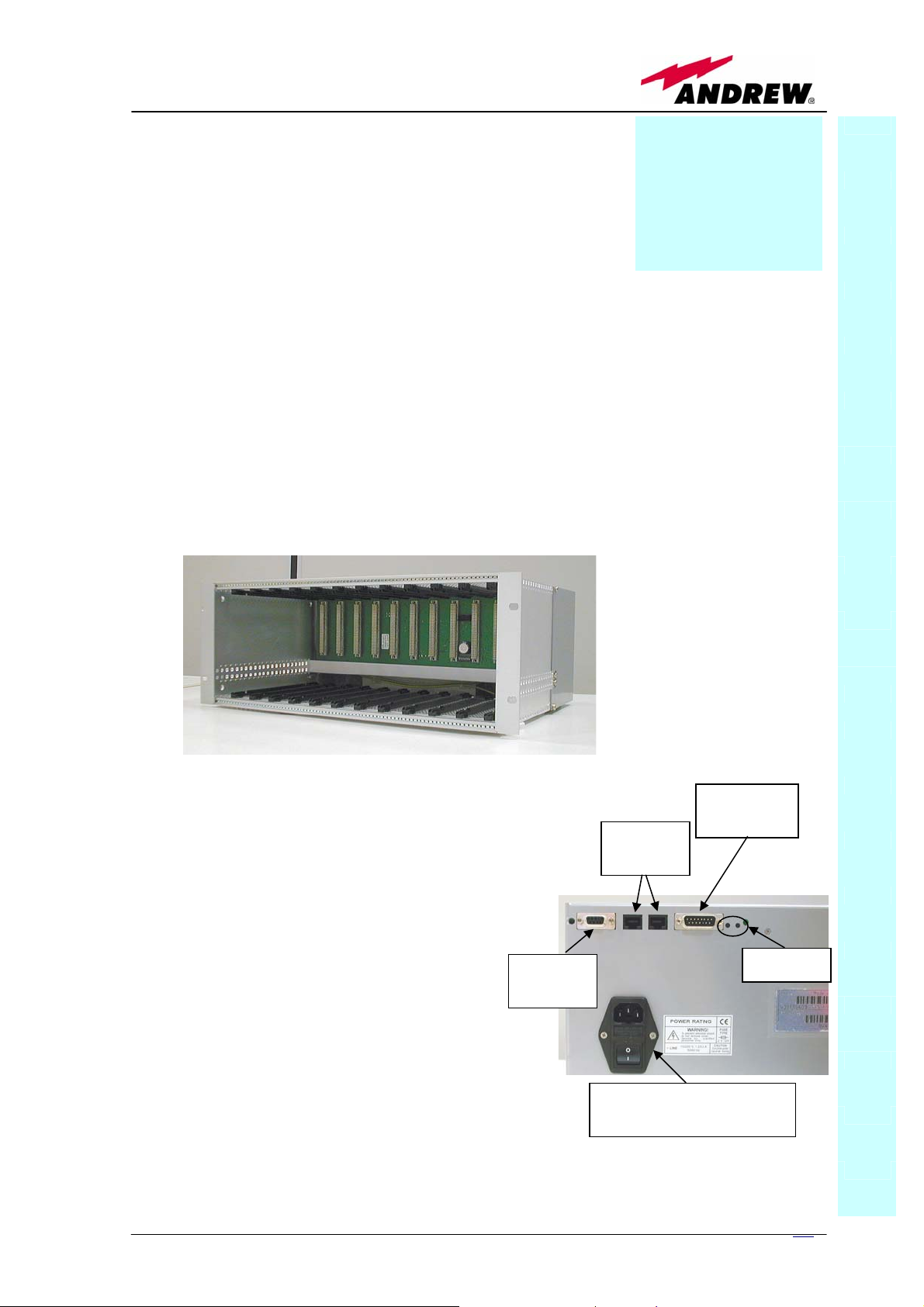
The TPRNx4 is a 19”subrack where all the Britecell Plus
plug-in modules can be inserted. Britecell Plus
equipment provides a wide variety of these sub-rack
models differentiated by power supply. Each one is
provided with:
• 12 free slots, each with Height=4HE, Width=7TE
• Power supply 220 Vac or -48 Vdc
• Locally or remotely connectable through:
¾ RS232 serial port
¾ RS485 two-wire bus
¾ sub-D 15 pin male-connector
• Internal microcontroller for I2CBUS alarm collection
• Manual reset button, able to re-initialize both the inserted modules and the
TPRN microcontroller
• Manual stand-by button, able to re-initialize the inserted modules, while
keeping the TPRN microcontroller working.
Fig. 5.1: Front view of the TPRN sub-rack with power
supply and communication ports on the back
Fig. 5.2: Back view of the TPRN subrack with power supply and
communication ports on the back
RS232
port
Subrack
TPRNx4
RS485
ports
sub D 15
connector
buttons
Power supply (picture
shows 220Vac version)
TPRN
MN024-08
115

F
TPRN models
A brief description of all the available TPRN sub-racks is reported hereinafter.
Passive sub-rack (TPRN04)
• TPRN04 is a passive sub-rack. It does not provide power supply to any
inserted module, and therefore it is designed to host passive modules
only. It can be useful in a multi-sub-rack system, in case the customer
decides to put all the active modules in an active sub-rack, to be chosen
among the following ones.
220 Vac powered sub-racks (TPRN14 / TPRN24)
• TPRN14 is an active sub-rack designed to be fed through 220 Vac
universal mains. Both the connector for 220Vac power supply and the
communication ports are placed on the sub-rack rear. The 220 Vac power
supply is not redundant (ie, no spare adapter is provided).
• TPRN24 is an active sub-rack designed to be fed through 220 Vac
universal mains. Both the connector for 220Vac power and the
communication ports are placed on the sub-rack rear, and the 220 Vac
power supply is redundant: i.e., a spare adapter guarantees the correct
system operations even in case the main 220Vac adapter has a
breakdown.
TPRN
-48Vdc powered sub-rack (TPRN34)
• TPRN34 is an active sub-rack designed to be fed through –48 Vdc
negative supply. Both the connector for -48Vdc power supply and the
communication ports are placed on the sub-rack rear.
TPRN power supply
All the TPRN models refer to one of the following power supplies.
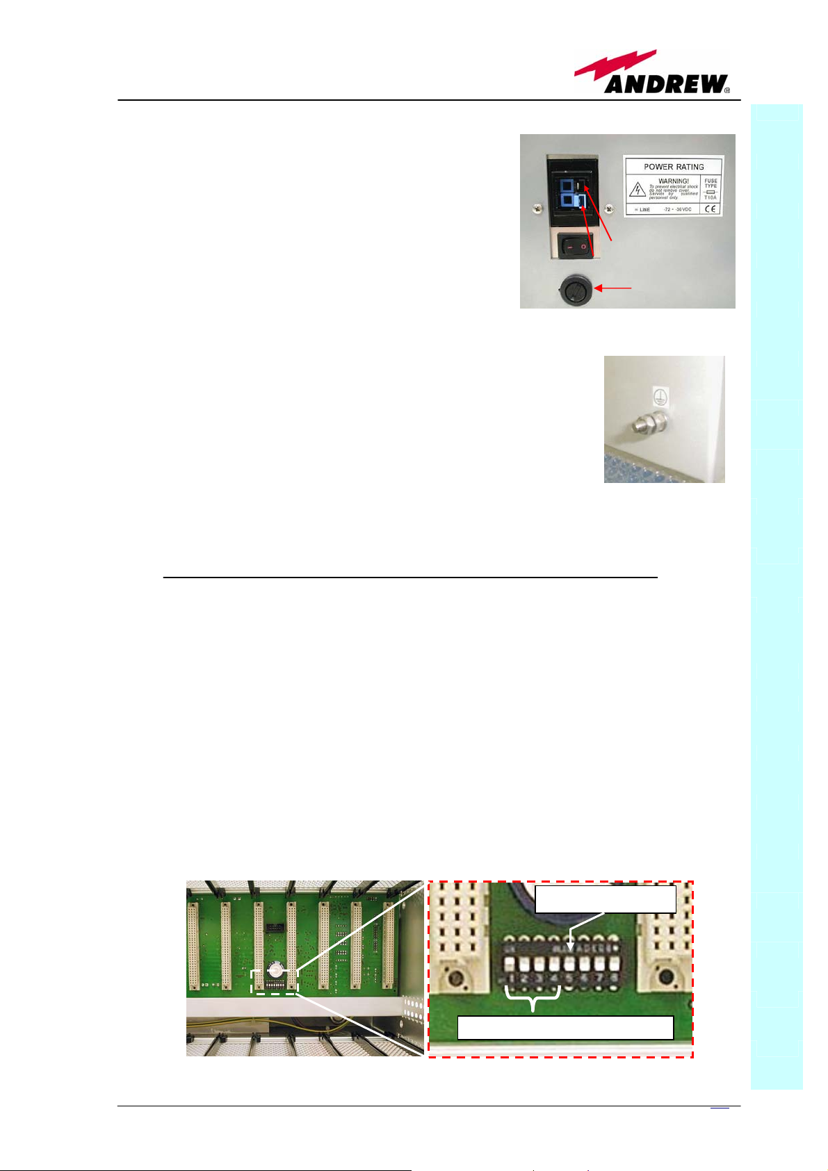
Universal mains
(85 to 264Vac, 50/60Hz).
This connector is mounted on the TPRN back
panel either for the redundant version or the
simple one. A ground terminal and a couple
of fuses are also included. Fuses have to be
replaced in case they fail (when it happens
the supervision system detects the failure).
Fig. 5.3: 85 to 264Vac connector
uses
116
User Manual
7
-48 Vdc
)
(-72 to -36 Vdc)
This connector is mounted on TPRN back panel.
A fuse is provided underneath the –48 Vdc
connector, and has to be replaced in case it
fails (when it happens the supervision system
detects the failure).
black terminal: 0V
blue terminal:-72 to -36Vdc
Fig. 5.4: -72÷-36Vdc connector
Whatever power supply is chosen (85 to 264 Vac or -72 to 36 Vdc) an additional external ground terminal is provided
on the TPRN rear (fig. 5.5).
Fig. 5.5: ground terminal on the rear
The external power supply (220Vac or -48Vdc) is converted into a +12Vdc
voltage allowing feeding the active modules inserted into the TPRN.
TPRN ports
The TPRN sub-rack is provided with a set of I/0 ports which allows the
connection to any external device.
RS232 serial port
The RS232 serial port can be used to connect the TPRN sub-rack to the
remote supervision unit or to a laptop running LMT software. Please note that
a standard RS232 cable is needed.
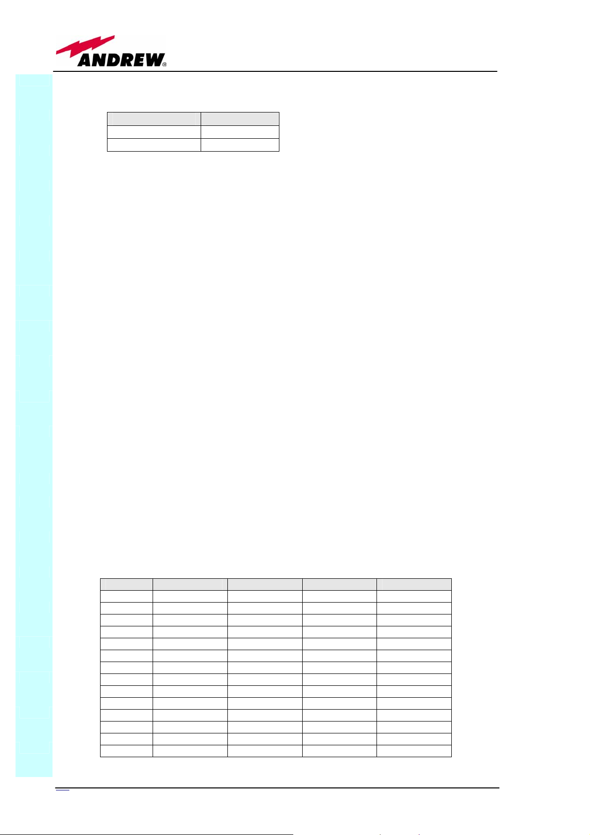
The connection baud rate can be set to 9600bps or 19200bps, by properly
setting the dip-switch 5 standing on the interior TPRN backplane (fig. 5.6).
The baud rate setting through dip-switch 5 is shown in table 5.1.
Baud-rate dip-switch (5)
RS485-addressing dip-switches (1-4
Fig. 5.6: Dip-switches on TPRN backplane.
TPRN
MN024-08
11
g
p
-
TPRN
Baud rate [bps] Dip-switch 5
9600 OFF
19200 ON
Table 5.1: Setting RS232 baud
rate throu
h di
switch 5
Whichever baud rate you choose through dip-switch 5, remember that:
• the same RS232 connection speed must be set up on the remote
supervision unit
• the baud rate which is selected through the dip-switch 5 sets the
connection speed for both the RS232 port and the RS485 port as the
TPRN uses both ports with the same rate.
RS485 port
The RS485 port consists of two RJ45 connectors, which can both work as
input or output ports towards a RS485 bus.
This RS485 bus has to be used in order to connect a multi sub-rack system to
the remote supervision unit. In this case:
• the TPRN sub-racks have to be connected one another via RS485 bus
in a daisy chain;
• In order to monitor the whole system, the remote supervision unit has
to be connected to one of the TPRN sub-racks through RS232 port.
Before connecting the TPRN sub-racks belonging to a multi-sub-rack system,
remember to assign an exclusive binary address to each one. This is essential
in order to let the supervision system recognize the different master units
without any conflict.
The binary address assignment can be done through dip-switches 1,2,3,4,
which stand on interior TPRN backplane (see figure 5.6). A list of the
correspondences between the addresses and the dip-switches is provided by
table 5.2: simply note that dip-switch 1 is the least significant binary digit,
while dip-switch 4 is the most significant one.
Address Dip-switch 1 Dip-switch 2 Dip-switch 3 Dip-switch 4
0001 ON OFF OFF OFF
0010 OFF ON OFF OFF
0011 ON ON OFF OFF
0100 OFF OFF ON OFF
0101 ON OFF ON OFF
0110 OFF ON ON OFF
0111 ON ON ON OFF
1000 OFF OFF OFF ON
1001 ON OFF OFF ON
1010 OFF ON OFF ON
1011 ON ON OFF ON
1100 OFF OFF ON ON
1101 ON OFF ON ON
1110 OFF ON ON ON
Table 5.2: Dip-switches address settings
118
User Manual
The baud rate of the RS485 ports is the same of the RS232 port as per the
dip-switch 5 setting.
Whichever baud rate you choose, remember that:
• the same RS485 connection speed has to be set up on all the
connected device (TPRN sub-racks or TSUN remote supervision unit);
• the baud-rate which is selected through the dip-switch 5 sets the
connection speed for both the RS485 port and the RS232 port.
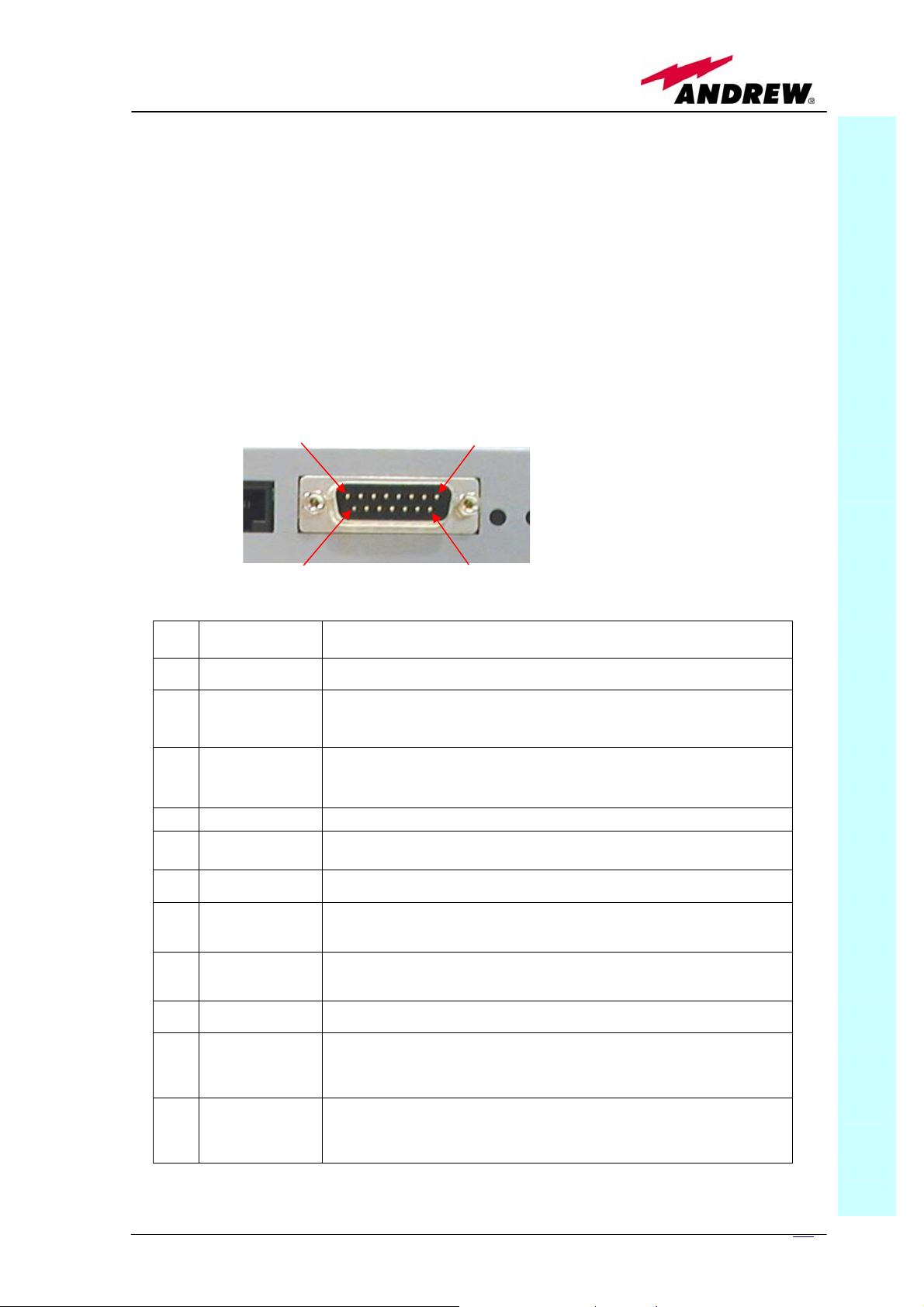
Sub-D 15 poles male connector
The TPRN sub-rack provides a sub-D 15 poles male connector, shown in fig.
5.7.
PIN 1
PIN 8
Fig. 5.7: sub-D 15 poles
male connector
PIN Name Meaning
Ground It is a ground terminal for digital inputs, i.e. for pin 2, 3, 9, 10.
1
Digital input n.1
2
(SW assignable)
Digital input n.2
3
(SW assignable)
Disconnected pin No meaning
4
Summary of
5,6
major alarms
Summary of
7,8
minor alarms
Digital input n.3
9
(SW assignable)
Digital input n.4
10
(SW assignable)
Disconnected pin No meaning
11
Digital output n.1
12,13
(SW assignable)
Digital output n.2
14,15
(SW assignable)
Tab. 5.3: Functional description of pins provided by sub D male connector.
This port can be used to monitor external equipment status. Once a default
working status has been assigned (through supervision system) to this input port,
any change is detected as a failure signal.
This port can be used to monitor external equipment status. Once a default
working status has been assigned (through supervision system) to this input port,
any change is detected as a failure signal.
These pins present an open circuit if a major alarm is active on the TPRN subrack or on any module hosted in it.
These pins present an open circuit if a minor alarm is active on the TPRN subrack or on any module hosted in it.
This port can be used to monitor external equipment status. Once a default
working status has been assigned (through supervision system) to this input port,
any change is detected as a failure signal.
This port can be used to monitor external equipment status. Once a default
working status has been assigned (through supervision system) to this input port,
any change is detected as a failure signal.
These pins are terminals of an output port (output relay 1), which can be driven
through the supervision system. The output port can be set to “open” or “close”
condition. These 2 statuses can be used to pilot any external device connected to
subD-15 connector.
These pins are terminals of an output port (output relay 2), which can be driven
through the supervision system. The output port can be set to “open” or “close”
condition. These 2 statuses can be used to pilot any external device connected to
subD-15 connector.
TPRN
MN024-08
119

As highlighted in the previous table, this connector provides:
• 4 opto-isolated input ports which can be used to reveal any failure
condition on external equipment. The default status of these input
ports can be defined through the supervision system. After that, any
change from default status will be revealed as a failure signal.
• a summary of major and minor alarms related to failures detected not
only on the TPRN sub-rack, but also on any active modules hosted by
the TPRN itself.
TPRN
• 2 relay output ports, which be can used to drive any external device
connected to subD-15 pins adapter. By using the supervision system
each of these output ports can set up on “open” or “close” conditions.
A more detailed description of the meaning and functionality of each pin are
reported in table 8. The pins are numbered from left to right, and from top to
bottom (refer to fig. 18).
: The TPRN sub-rack uses I2Cbus standard protocol to collect status and
Note
alarm information from hosted modules. Thanks to that, the alarm summaries
(provided through pins 5-6 and 7-8) report major and minor failures related
not only to TPRN sub-rack but also to any hosted module.
TPRN alarms
A full description of all TPRN alarms is provided by the Supervision system.
The table 4.8 provides a brief description of the TPRN alarms, as they are
reported by the LMT software o
ALARM
CODE
(TSUN
description)
Redundant
supply active
(only for
redundant
power supply
versions)
Power Supply
alarm
I2CBUS bus
error
Temperature
alarm
Aux input
alarm nr0
Aux input
alarm nr1
ALARM
DESCRIPTION
Backup power supply
activated
There is a
degradation on the
power supply
provided to the
boards
Internal I2CBUS
communication
malfunction
Over-temperature
alarm
The device
connected to the
input alarm port 0
caused an alarm
condition
The device
connected to the
input alarm port 1
caused an alarm
ACTIVE
LED
YELLOW MAJOR Return the unit MINOR
RED MAJOR Return the unit MAJOR
YELLOW CRITICAL
YELLOW MINOR
RED CRITICAL
RED MAJOR
SUPERVISION
PRIORITY
LEVEL
ACTION
RECOMMENDED
Check if the fault is
on the unit (see
supervision
system). If not
return the unit
Check ventilation
and environment
Check the status of
the connected
device
Check the status of
the connected
device
RELÉ
PRIORITY
LEVEL
(subrack)
MINOR
MINOR
-
-
120
User Manual

condition
Aux input
alarm nr2
Aux input
alarm nr3
The device
connected to the
input alarm port 2
caused an alarm
condition
The device
connected to the
input alarm port 3
caused an alarm
condition
RED MINOR
RED WARNING
Check the status of
the connected
device
Check the status of
the connected
device
Tab. 5.4: Description of the alarms of the TPRN subrack
Warning (recommended for system designing and
installing)
Providing a correct heat dissipation
For a correct use of the TPRN sub-rack, it is important to verify that:
-
-
• the system is designed in order to put no more than 8 TFLN inside a
TPRN sub-rack. This guarantees a proper heating dissipation for the
system. In case you want to install more than 8 it is important to
provide the sub-rack with a proper ventilation system;
• active and passive modules should be alternated as much as possible
inside the TPRN sub-rack avoiding too many active cards being inserted
close together;
• in case the system consists of more than one TPRN sub-rack, a
minimum distance of 1 HE has to be kept between nearby TPRN subracks to ensure proper heat dissipation. The rack containing the TPRN
sub-racks has to be large enough to guarantee this correct distance
between master units.
Minimizing equipment costs
In order to reduce the cost of Britecell Plus equipment, a multi-sub-rack
system should be designed according to the following guidelines:
• a passive sub-rack (TPRN04) may be used to house only passive
modules;
• an active sub-rack (TPRN14, TPRN24, TPRN34) may be used to sustain
all the active modules, and some of the passive ones (as stated above,
it is advisable to alternate active and passive cards into an active subrack).
TPRN
MN024-08
121

Setting the dip-switches in a multi sub-rack system
If you are installing a multi-sub-rack system, remember to assign each subrack an exclusive binary address, by properly setting dip-switches 1,2,3,4 on
the interior TPRN backplane (see fig. 5.6 and Tab.5.2). Dip-switch 5 has to be
set on each TPRN sub-rack in order to fix the baud rate for RS485 and RS232
port. Connecting TPRNs through RS485 port is necessary when supervising
the whole multi sub-rack system through the remote supervision unit (to be
set at the same baud rate).
TPRN Installation
The TPRN kit provides:
• 1 TPRN sub-rack
TPRN
• 1 suitable power cord
• 1 standard RS232 cable (male-female), 2m
• 1 CD Manual
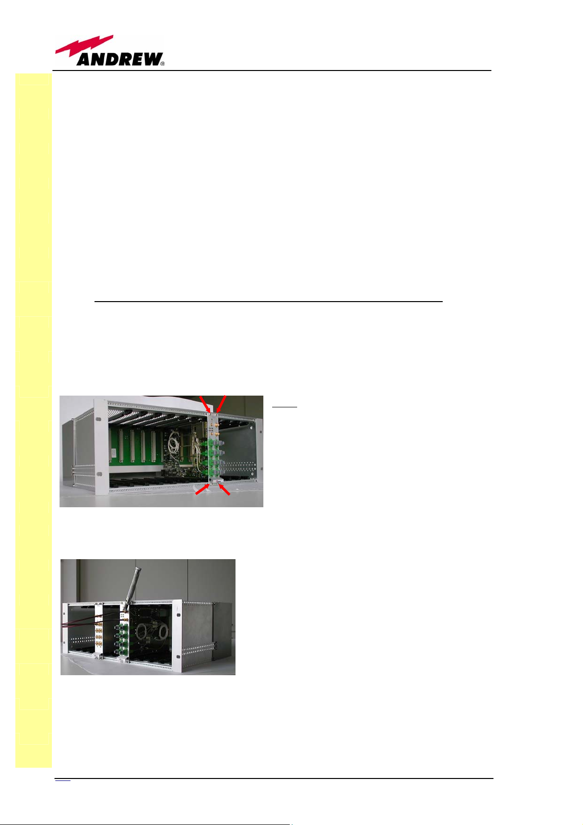
First of all insert the sub-rack into the cabinet and apply 4 screws (not
provided) in order to fix it (fig. 5.8a).
To have a correct TPRN installation, distance between the front
door of the rack and the front side of the TPRN should be at
least 15cm otherwise RF and optical cables can be damaged
when cabinet door is closed.
Fig. 5.8(a): At each front-corner
the subrack is provided with a
screw in order to be fixed to the
Leave at least 1HE distance between two subracks
in order to facilitate air circulation.
Leave at least a 1HE free space between the
bottom or the top of the cabinet and the TPRNs.
1HE
Fig. 5.8(b): Distance between
subracks should be at least 1HE in
Connect the ground to the safety ground terminal. Then, connect the power
supply connector to the mains.
122
User Manual

Power
supply
Ground
terminal
Fig. 5.8(c) : Power supply and
ground terminals on the rear
side of the TPRN subrack
TPRN Start-up
Before switching on the TPRN sub-rack, make sure that:
• all expected modules have been inserted
• the modules have been connected each other by RF jumpers, according
to what has been planned during system design
• every TFLN contained in the Master Unit has been connected to its TFAx
remote units
• each TFAx remote unit has been connected to its coverage antennas
• the remote supervision unit (if present) has been connected/housed
to/into the Master Unit
• different sub-racks have been connected each other via bus RS485 and
each of them have different addresses
• the rack housing the TPRN is large enough to leave a minimum
distance of 1HE between contiguous TPRN sub-racks
Remember that TFAx remote units have to be switched on before relevant
Master Unit.
Once the TPRN sub-rack has been switched on, the system behaviour can be
summarized as per the following steps:
• About 10sec after the TPRN sub-rack has been switched on, all TFLN
modules housed in the TPRN itself begin a “discovery” phase in order
to identify and collect status of the connected TFAx remote units.
While the discovery phase is working (max. 4min. depending on the
system complexity) each TFLN general alarm (i.e., LED “┌┘”) blinks,
whereas the other TFLN LEDs go on showing the detected status.
Do not connect/disconnect any cable or piece of equipment until all
TFLN modules have finished the discovery phase. This may result in
failing the identification of TFAx. Anyway during the discovery phase,
the whole system still works correctly as discovery process aims to
collect information about TFAx but without affecting basic system
functionalities.
TPRN
MN024-08
123

TPRN
Note: in case discovery doesn’t start automatically, check through the LMT or the
remote supervision whether it has been disabled (refer to LMT or remote supervision
system manuals for further information).
• O
nce the discovery has finished, the general alarm (i.e. the LED “┌┘”)
on each TFLN panel stops blinking and switches OFF (provided that
the TFLN master optical TRX is not affected by a general failure).
TPRN troubleshooting
In case a TPRN sub-rack shows any problem a more detailed status and
alarm description could be provided through the remote supervision unit.
A complete overview of TPRN alarms is reported in the previous Table 5.4.
The power supply degradation occurs in case the +12Vdc power falls below
an in factory set threshold level. In this case, TPRN automatically turns to
standby mode so that no over-current gets through the circuitry of hosted
modules, thus preserving the system integrity. Once power supply has been
repaired, the TPRN needs to be rebooted. In case the TPRN sub-rack is
equipped with a redundant power supply (TPRN24), a degradation of the
+12 Vdc power results in an automatic switching from main to spare
converter. In case also redundant power supply degrades the TPRN
automatically turns to stand-by mode. Once the power supply has been
repaired the TPRN needs to be rebooted.
2
Cbus alarm occurs when TPRN sub-rack cannot communicate with one or
I
more hosted module. Each TPRN slot is able to automatically detect the
presence of a module inside the slot. If the module is detected but TPRN is
not able to communicate with it through I
Note
: at commissioning remember to mask the unused slots through LMT
software (please refer to the relevant manual for more infor mation) to avoid
not significant alarm being switched on.
In order to carry out a troubleshooting procedure, please check LMT or
supervision system handbooks.
2
Cbus alarm is activated.
124
User Manual

MN024-08
125

5.2. Master Optical TRX, TFLN
TFLN
126
User Manual
7
Module name:
Main tasks carried out
by the TFLN module
Downlink (DL):
¾ RF-to-optical conversion of
the input RF signal
¾ Optical splitting: input RF
signal is split onto 4 optical outputs
Uplink (UL):
¾ Optical-to-RF conversion of the 4 input optical signals
¾ Automatic Gain Control (AGC) of each converted signal to compensate
optical losses;
¾ RF combining of the 4 adjusted signals into a single RF output
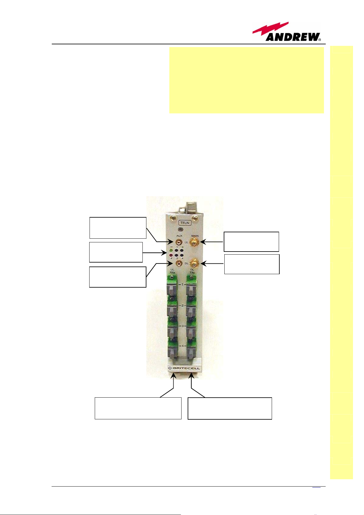
Master Optical TRX
TFLN
UL RF Auxiliary
Output (SMB-m)
Status and
Alarm LED
DL RF Auxiliary
Input (SMB-m)
UL RF Main
Output (SMA-f)
DL RF Main
Input (SMA-f)
TFLN
UL Optical Fibre
Adapters (SC-APC)
DL Optical Fibre
Adapters (SC-APC)
Fig. 5.9 . The TFLN Master Optical TRX
MN024-08
12
RF ports
• 1 DL RF input port
• 1 auxiliary DL RF input port
• 1 UL RF output port
• 1 auxiliary UL RF output port
Note: nominal input levels required at RF ports is +10dBm (please refer to
datasheet for further information), as well as RF outputs may require a power
adjustment to fill within the BTS receiving range.
In order to fulfil these requirements, external UL and DL attenuations may be
required (see TBSI module)
.
TFLN
Optical ports
• 4 DL optical output ports (SC/APC)
• 4 UL optical input ports (SC/APC)
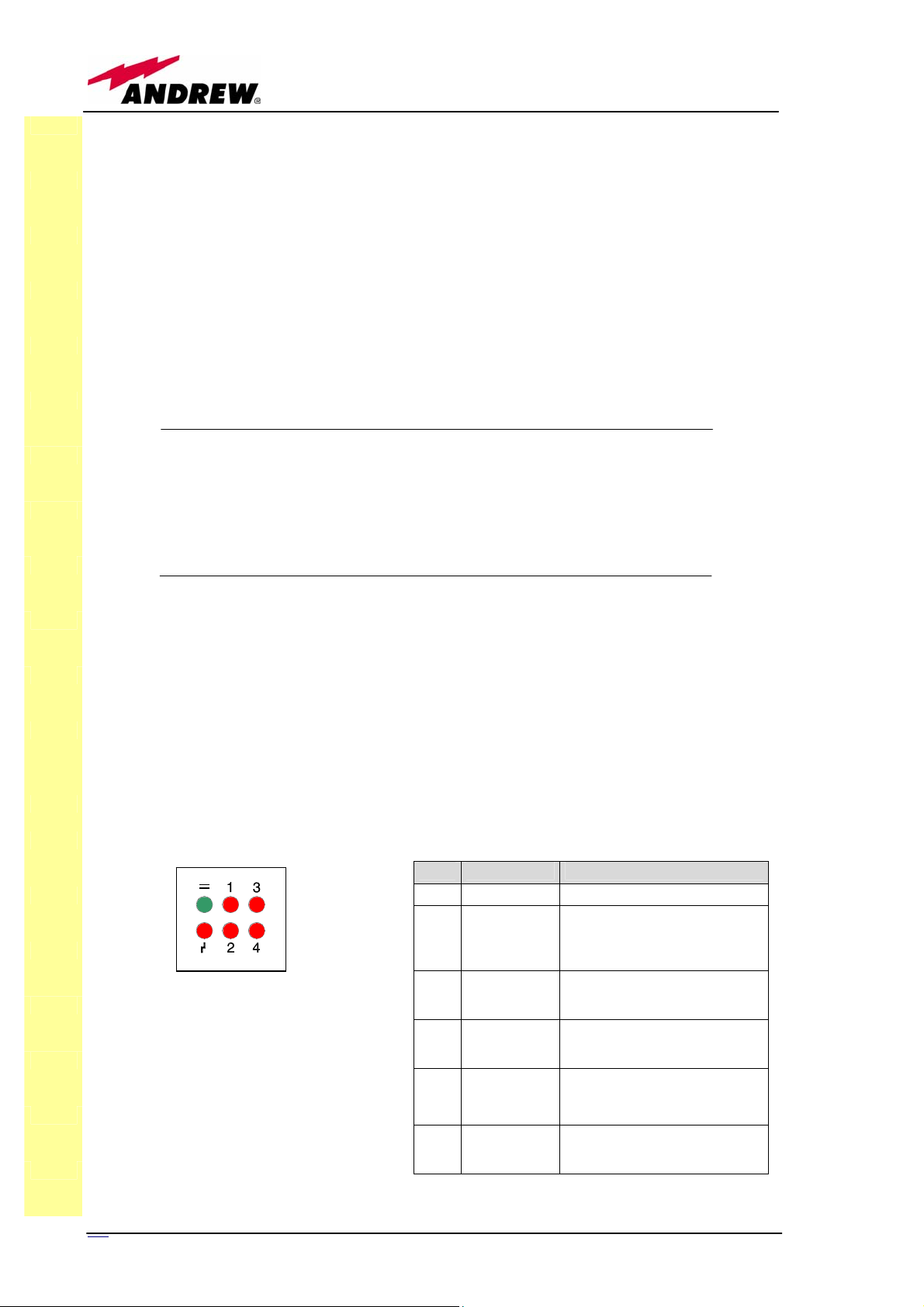
TFLN visual alarms
The TFLN front panel is provided with 6 LEDs (see on the right), showing
status and alarm information.
LED meaning is reported on the rightward table.
Further information about alarm status is delivered by Britecell Plus
supervision system.
Note: In case the four TFLN optical output ports are not all connected to
remote units, the unused ports must be properly masked at commissioning in
order to avoid spurious alarms (please refer to LMT manual).
Fig. 5.10 :LED panel
on TFLN front side
Label LED colour Meaning
= Green
Red
┌┘
1
Red
2
Red
3
Red
4
Red
Power supply status OK
General TFLN failure, it can be:
- TFLN laser failure
- UL or DL amplifier failure
- TFLN short circuit
Low UL optical power received
from remote unit 1 (fault in optical
link 1 or remote unit 1 failure)
Low UL optical power received
from remote unit 2 (fault in optical
link 2 or remote unit 2 failure)
Low UL optical power received
from remote unit 3 (fault in optical
link 3 or remote unit 3 failure)
Low UL optical power received
from remote unit 4 (fault in optical
link 4 or remote unit 4 failure)
Tab. 5.4: Meanings of the LEDs on TFLN front-side
128
User Manual
TFLN power supply
Each TFLN master optical TRX is supplied by the sub-rack back-plane (12V).
The power consumption of each TFLN master optical TRX is 12W.
Warnings (to be read before the TFLN installation)
Dealing with optical output ports
• The TFLN master optical TRX contains semiconductor lasers. Invisible laser
beams may be emitted from the optical output ports. Do not look towards
the optical ports while equipment is switched on.
Handling optical connections
• When inserting an optical connector, take care to handle it so smoothly
that the optical fibre is not damaged. Optical fibres have to be single-mode
(SM) 9.5/125µm.
• Typically, Britecell Plus equipment is provided with SC-APC optical
connectors. Inserting any other connector will result in severe damages.
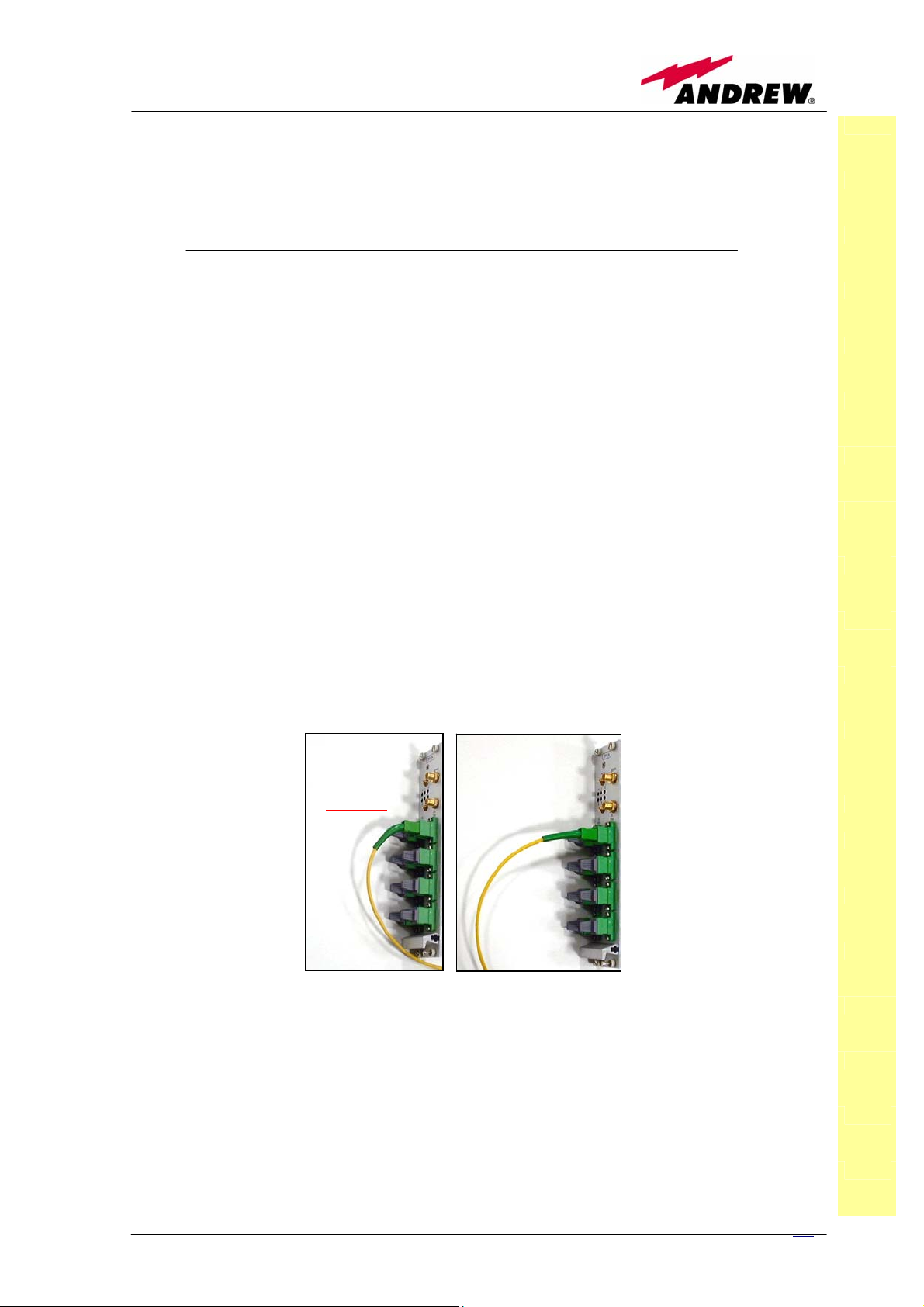
• Do not force or stretch the fibre pigtail with radius of curvature less than 5
cm. See fig. 19 for optimal fibre cabling.
• Remove adapter caps only just before making connections. Do not leave
SC-APC adapters open, as they attract dust. Unused SC-APC adapters must
always be covered with their caps.
• Do not touch the adapter tip. Clean it with a proper tissue before inserting
each connector into the sleeve. In case adapter tips need to be better
cleaned, use pure ethyl alcohol
Inserting or removing TFLN modules
• Do not remove or insert any TFLN module into TPRN sub-rack before
having switched off main power supply.
• The TFLN modules must be handled with care, in order to avoid damage to
electrostatic sensitive devices.
• When installing TFLN modules in the sub-rack, take care to alternate active
and passive cards in order to ensure proper heat dissipation.
WRONG
Fig. 5.11: Fibre Optic bending
OPTIMAL
TFLN
MN024-08
129
TFLN
• In a multi-sub-rack system, remember to assign to each sub-rack a proper
RS485 bus address before installing the modules (please refer to TPRN
section for further details).
TFLN positioning
• In case no ventilation system is installed, do not insert more than 8 TFLN
modules into a sub-rack.
•
In case more than 8 TFLN modules have to be housed into a TPRN subrack, it’s advisable to install the TPRN sub-rack inside a rack with forced
ventilation.
•
Take care to meet expected requirements on RF ports. An adjustable
attenuator could be necessary when the power coming from the BTS
exceeds the required levels to avoid damages in Britecell Plus circuitry or
increase of spurious emissions.
TFLN installation
The TFLN master optical TRX is housed in a TPRN sub-rack and its dimensions
are 19” width and 4HE height. A TFLN module can be accommodated in any
of these 12 slots.
: In case a new TFLN module has
Note
to be installed in a still working Master
Unit, switch off the sub-rack before
inserting the plug-in TFLN module
Firstly, gently insert the TFLN in one of
the 12 available slots, and lock the 4
screws on the front corners.
Fig. 5.12: Screws to be fixed at the corners of the TFLN front side
Then connect the UL and DL RF cable to
the TFLN UL and DL ports, respectively.
Use a specific torque wrench to fix these
RF cables to DL and UL ports.
Fig. 5.13: UL and DL RF cables are to be fixed by a torque wrench
130
User Manual

Remove the caps from TFLN optical ports
and connect the SC-APC fibre optic cables to
the ports.
UL and DL cables coming from the same
remote unit have to be connected to UL and
DL ports marked by the same number on the
TFLN front panel.
Fig. 5.14: Take off the caps and connect the fiber optics cables properly
As you switch on the system, carefully refer to the TFLN Start-Up section.
Remember that remote units should be switched on before than the Master
Unit in order to follow a correct Start-Up procedure.
TFLN start-up
Before the Master Unit is switched on, make sure that:
• all expected modules have been inserted into the Master Unit
• the modules have been connected each other by RF jumpers, according to
what planned in the system design
• every TFLN master optical TRX has been connected to relevant remote
units
• each remote unit has been connected to its coverage antennas
• the remote supervision unit, if present, has been connected to the Master
Unit
• different Master Units are connected each other via bus RS485
After that, remember that only when all the remote units are already on, the
Master Unit itself can be turned on.
Once the Master Unit has been switched on, the TFLN behaviour at system
start-up can be summarized as per the following steps:
1. When Master Unit is turns on all the six LEDs upon the TFLN front panel
go on for a couple of seconds. After that, the green LED remains on
(indicating proper power supply) while the other LEDs indicate the
master optical TRX status, according to the following table.
: In case unused optical ports of the TFLN have not been masked
Note
through LMT yet, corresponding LEDs will be on. If so, wait for the end
of step 3 (discovery phase) then use LMT to mask them (please refer to
relevant handbook)
2. About 10 seconds after the system has been switched on, TFLN module
begins a “discovery” phase to identify connected remote units. This
operation is necessary to collect all the information to be provided to
the supervision system.
TFLN
MN024-08
131

TFLN
Label LED colour Status
= Green ON
(power supply is on)
┌┘
1 Red OFF
2 Red OFF
3 Red OFF
4 Red OFF
Red OFF
(no major failure affects TFLN operations)
(no major failure affects corresponding remote unit or UL
connection)
(no major failure affects corresponding remote unit or UL
connection)
(no major failure affects corresponding remote unit or UL
connection)
(no major failure affects corresponding remote unit or UL
connection)
Table 5.5: Status of the TFLN LEDs in full-working conditions
During the discovery phase the TFLN general alarm (LED
┌┘) blinks while the
other LEDs go on showing previously detected status. Time dedicated to
discovery phase can be at maximum 4min and depends on system
complexity.
Do not connect/disconnect any cable or any piece of equipment during the
discovery phase. This may result in failing the identification of remote units.
Please note that, while the discovery phase is running, the whole system is
working correctly as discovery operations aim only to collect information
about remote units without affecting the system functionalities.
: in case discovery doesn’t start automatically, check through the LMT or
Note
the remote supervision whether it has been disabled (refer to LMT or remote
supervision system manuals for further information).
Once the discovery is finished, the TFLN general alarm (LED ┌┘) stops
blinking and switches OFF. The power supply LED (green LED) remains on
while LEDs 1,2,3,4 show either the status of the remote units or the quality of
the UL connections. In case some of these LEDs remain on, check if they refer
to unused optical ports or not. In this case use LMT software to mask it
otherwise if they refer to connected remote units and remain on, please refer
to troubleshooting procedure.
Removing a TFLN module
Switch off the Master Unit power supply, remove the SC-APC optical
connectors, and insert the protection caps into TFLN optical ports. Then
• unscrew the 4 screws and slowly remove the card.
• put the removed TFLN card in its safety box.
• switch on again the Master Unit power supply, and refer to Start Up
section.
132
User Manual

TFLN troubleshooting
In case a TFLN master optical TRX has any problem, this will be easily
revealed through LEDs on its front panels otherwise troubleshooting can be
carried out through LMT or supervision system.
LEDs on TFLN front panel detect not only failures of the TFLN board itself but
they also reveals malfunctions located on related remote units.
ALARM CODE
(TSUN
description)
RX1 optical power
fail
RX1 AGC out of
range
RX2 optical power
fail
RX2 AGC out of
range
RX3 optical power
fail
RX3 AGC out of
range
RX4 optical power
fail
RX4 AGC out of
range
Major Remote
Unit 1
Major Remote
Unit 2
Major Remote
Unit 3
Major Remote
Unit 4
DL laser alarm
UL RF alarm
DL RF alarm
Board failure
alarm
Temperature
alarm
ALARM
DESCRIPTION
The optical power
received on the UL1 is
too low and can’t no
more be compensated
The optical power
received is under the
allowed 3dB optical
loss but it can be
compensated
The optical power
received on the UL2 is
too low and can’t no
more be compensated
The optical power
received is under the
allowed 3dB optical
loss but it can be
compensated
The optical power
received on the UL3 is
too low and can’t no
more be compensated
The optical power
received is under the
allowed 3dB optical
loss but it can be
compensated
The optical power
received on the UL4 is
too low and can’t no
more be compensated
The optical power
received is under the
allowed 3dB optical
loss but it can be
compensated
Alarm from RU1
Alarm from RU2
Alarm from RU3
Alarm from RU4
A fault occurs on the
DL laser
HW failure on the UL
RF section
HW failure on the DL
RF section
General failure on
board
Over-temperature
alarm
Tab. 5.6: TFLN alarm description
ACTIVE
LED
RED
(LED1)
NONE MINOR
RED
(LED2)
NONE MINOR
RED
(LED3)
NONE MINOR
RED
(LED4)
NONE MINOR
RED
(LED1)
RED
(LED2)
RED
(LED3)
RED
(LED4)
RED (┌┘) MAJOR Return the unit MAJOR
RED (┌┘) MAJOR Return the unit MAJOR
RED (┌┘) CRITICAL Return the unit MAJOR
RED (┌┘) MAJOR Return the unit MAJOR
NONE MINOR
SUPERVISION
PRIORITY
LEVEL
CRITICAL
CRITICAL
CRITICAL
CRITICAL
-
-
-
-
ACTION
RECOMMENDED
Check the UL1 fibre
and the remote unit
laser status
Clean optical
connectors
Check the UL2 fibre
and the remote unit
laser status
Clean optical
connectors
Check the UL3 fibre
and the remote unit
laser status
Clean optical
connectors
Check the UL4 fibre
and the remote unit
laser status
Clean optical
connectors
Check remote unit
status
Check remote unit
status
Check remote unit
status
Check remote unit
status
Check ventilation
and environment
RELÉ
PRIORITY
LEVEL
(subrack)
MAJOR
MINOR
MAJOR
MINOR
MAJOR
MINOR
MAJOR
MINOR
MAJOR
MAJOR
MAJOR
MAJOR
MINOR
TFLN
MN024-08
133

TFLN
The previous table reports a brief description of the TFLN alarms, together
with a reference to the corresponding alerted LEDs.
As the table shows, LEDs on the TFLN front panel signal all high priority
alarms while minor alarms, which detect critical situations which should be
checked and tested in order to avoid future possible system faults, are only
revealed by LMT or supervision system.
Each TFLN is provided with an AGC system which compensates optical losses
<3 dB. TFLN LED alarms switch on when the estimated optical losses are
>4dB, the AGC not being able to compensate these losses any more.
One of LEDs 1, 2, 3 or 4 might turn on not only to indicate a high optical loss
detected by TFLN, but also to reveal a remote unit failure. Understanding the
reason why one of LEDs 1, 2, 3 or 4 is on (a remote unit failure, an optical
cable fault or an external equipment malfunction) can be done following the
troubleshooting procedure reported hereinafter.
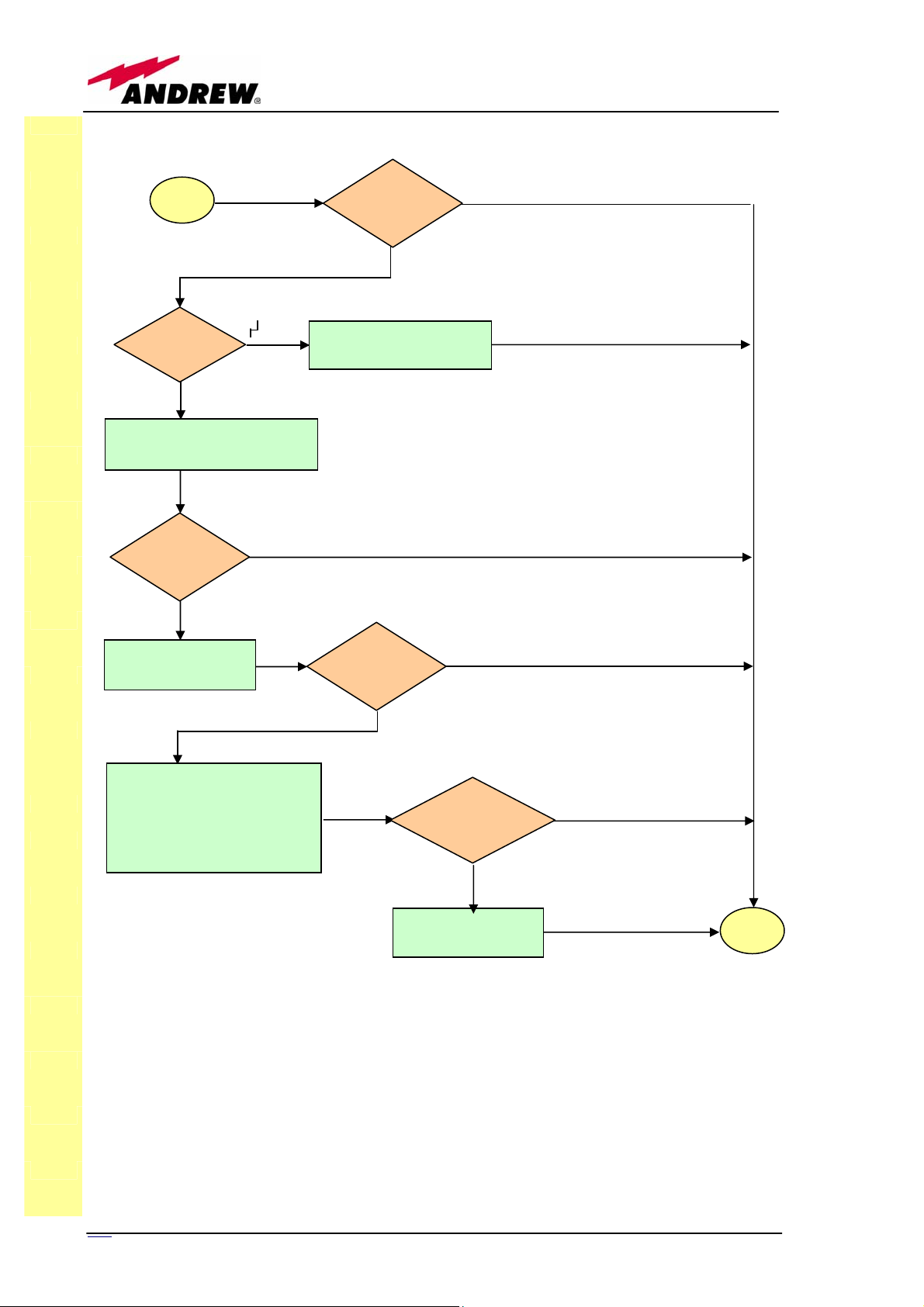
Quick troubleshooting procedure
(The following procedure is summarized by the flow-chart in fig. 5.15a)
1. In case the TFLN general alarm (LED ┌┘) is on replace the faulty TFLN
master optical TRX with a new one and contact the manufacturer for
assistance.
2. In case one of the LEDs 1, 2, 3 or 4 is on, the corresponding TFLN
adapter might be dirty. Try cleaning it using pure ethyl alcohol. If the
LED is still on go to the corresponding remote unit side and check the
red LED upon TFAx warm side:
a. If it is off, the optical cables or the optical connections are
supposed to have some problem on UL path. Refer to fibre optic
UL troubleshooting for more information (fig. 21).
b. If it is on, refer to remote unit troubleshooting presented in the
previous remote unit section
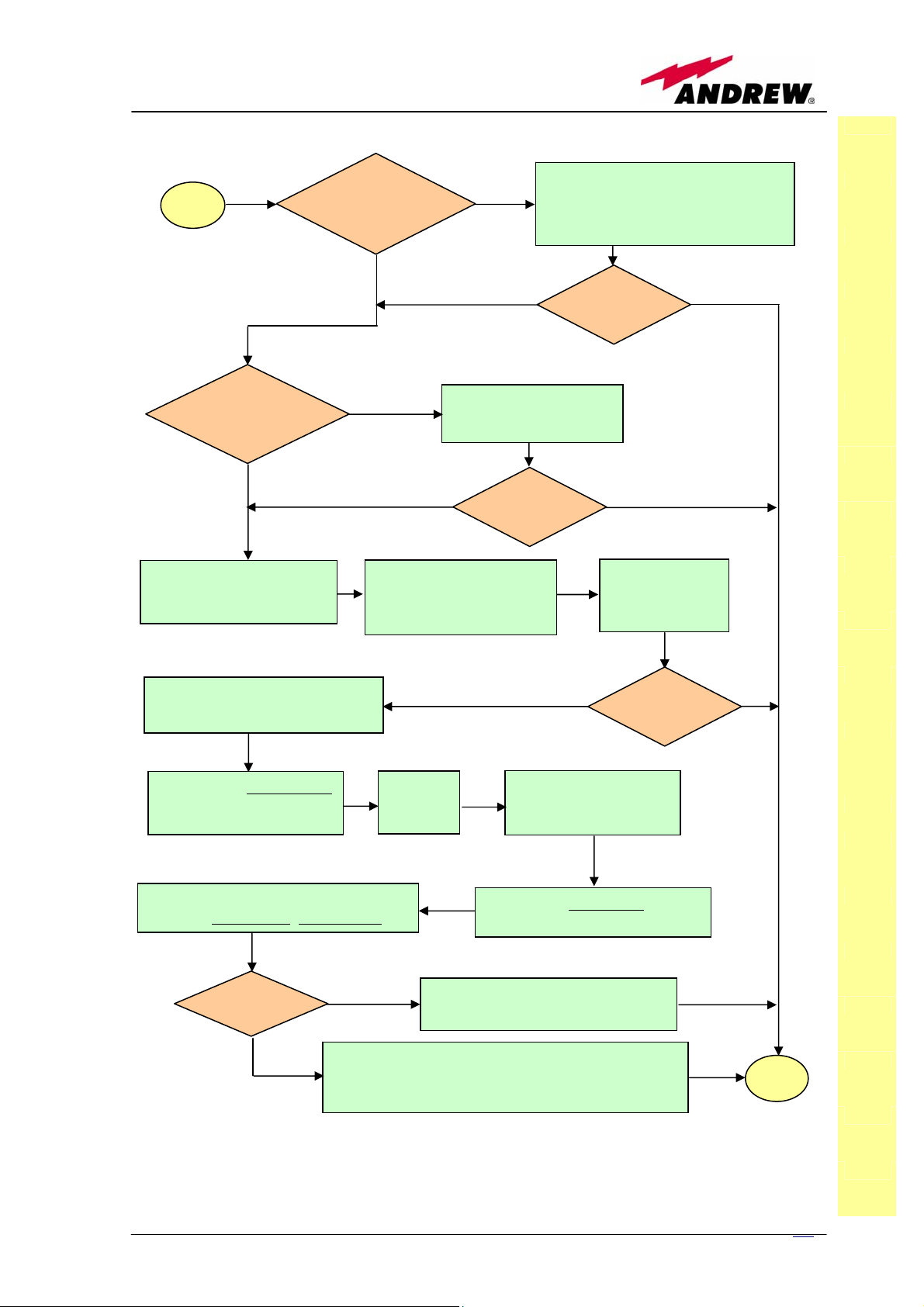
Fibre optic UL troubleshooting
(The following procedure is summarized by the flow-chart in fig. 5.15b)
1. Check if there is any point where the fibre experiences a small radius of
curvature. In this case, rearrange the optical path in order to avoid
sharp bends (if necessary, replace the optical cable with a longer one). If
this makes the TFLN red LED switch off, troubleshooting has been
successful. Otherwise, follow next steps.
2. Check if the SC-APC connectors are properly installed at both fibre ends
(i.e. TFLN and TFAx ports). If not fix better SC-SPC connectors to
relevant adapters. If this makes the TFLN red LED switch off,
troubleshooting has been successful. Otherwise, follow next steps.
3. Disconnect the optical fibre and clean it at both fibre ends (i.e. TFLN side
and TFAx side) then reconnect the fibre to relevant ports. In case this
makes the TFLN red LED switch off, troubleshooting has been successful.
Otherwise, follow next steps.
4. Disconnect the optical SC-APC connector from TFLN UL port, and
measure the output power P
(UL) at corresponding fibre end. Then, go
OUT
134
User Manual

to the TFAx side, disconnect the optical SC-APC connector from TFAx UL
port and measure the input power P
(UL) coming out of the TFAx UL
IN
port.
5. Calculate the UL fibre attenuation A
a. If A
> 4dB, the fibre optic cable has some problems or cable
UL
as: AUL [dB] = PIN(UL) – P
UL
path is too long. Replace it.
b. If A
< 4dB, then TFAx remote unit should be faulty. Before
UL
replacing it, check the TFAx status on supervision system and
contact for assistance
OUT
(UL)
TFLN
MN024-08
135
N
TFLN
start
Which red
LED is ON?
1, 2, 3 or 4
Clean corresponding SC-APC
optical adapter and connector
Is red LED
upon TFLN
still ON?
Yes
No
Go to corresponding
remote unit side
UL optical cables or optical
connections are supposed to
have some problems. Refer to
fibre optic UL troubleshooting
(fig. 5.15b)
Fig. 5.15 (a): Flow-chart describing the quick troubleshooting procedure
Is any red LED
ON upon the
TFLN?
Yes
Replace the faulty TFLN
Is red LED
No
upon remote
unit ON?
Yes
Is red LED
upon remote
unit still ON?
Refer to remote unit
troubleshooting
o
Yes
end
136
User Manual
7
g
N
N
es
No
N
es
p
p
p
es
No
es
start
Is there any small
radius of curvature
Yes
of the fibre?
Rearrange the optical path in order to
avoid sharp bends. If necessary
replace the optical cable with a
lon
er one.
o
Y
Is the red LED
o
upon TFLN still
ON?
Are SC-APC
connectors properly
installed at both fibre
ends?
Yes
Disconnect the optical fibre
and clean it at both ends.
Disconnect the optical SC-APC
connector from TFLN UL port.
Measure the output power
at the corresponding fibre
end
o
Fix SC-APC connectors
properly to adapters.
Y
Is the red LED
upon TFLN still
ON?
Clean the optical SC-APC
orts both on TFLN and
TFAx side.
Go to the
Disconnect the optical
TFAx
side
from TFAx UL
Re-connect the
fibre to relevant
Y
Is the red LED
upon TFLN still
SC-APC connector
ort.
orts.
ON?
No
TFLN
Calculate the UL fibre attenuation:
[dB]=input power - output powe r
A
UL
Measure the input power entering
the fibre.
Is AUL > 4dB?
Y
The TFAx remote unit should be faulty. Before
replacing it, verify its status through supervision
Fibre optic cable has some problems.
Replace it.
end
system and contact for assistance.
Fig. 5.15 (b): Flow-chart describing the fibre optic UL troubleshooting
MN024-08
13

5.3. Two-way Splitter/Combiner, TLCN2
TLCN2
138
User Manual
p
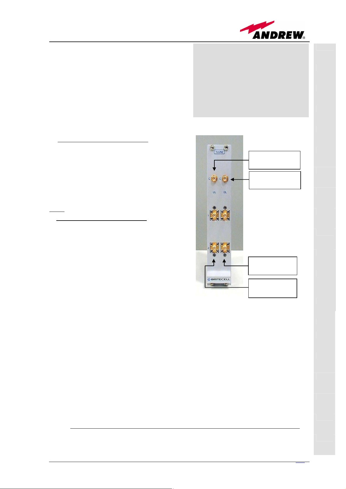
Module name:
Description:
The TLCN2, a bidirectional 2-way
splitter/combiner, provides two identical
combining sections for UL and DL which
can be used:
¾ to combine 2 RF signals into a
common RF output
¾ to split an RF input into 2 RF output
signals
It is a passive wideband module.
RF ports:
• 1 DL common RF port (“C”)
• 2 DL splitted RF ports (“1”,“2”)
• 1 UL common RF port (”C”)
• 2 UL splitted RF ports (“1”,“2”)
: each port is bidirectional.
Note
2-way splitter/
/combiner
TLCN2
UL common RF
port (SMA-f)
DL common RF
ort (SMA-f)
TLCN2 main applications
Main applications of the TLCN2 module are:
• Connecting a donor source to more than
one TFLN master optical TRX, so that:
¾ TLCN2 splits the DL input coming
from a donor source into 2 output
signals entering 2 different TFLN
master optical TRX
¾ TLCN2 combines the UL inputs
coming from 2 TFLN master optical
TRX into 1 common signal entering
the donor source
• Connecting a TFLN master optical TRX to more than one donor source
within the same service, so that:
¾ TLCN2 combines the two DL inputs coming from 2 donor sources into 1
output signal entering the TFLN master optical TRX or a cross band
coupler
¾ TLCN2 splits the UL input coming from TFLN master optical TRX or a
cross band coupler into 2 different output signals entering 2 different
donor sources.
More TLCN2 modules can be used in cascade connections.
Fig. 5.16: TLCN2 splitter/combiner
DL splitted RF
ports (SMA-f)
UL splitted RF
ports (SMA-f)
TLCN2
MN024-08
139

TLCN2 insertion loss
The TLCN2 insertion loss varies slightly with the frequency bands, as shown in
table 5.7.
When designing the system, remember to take into account the insertion loss
of the TLCN2 if present.
TLCN2 insertion loss
700-1400MHz 1400-2200MHz 2200-2500MHz
3.7 ± 0.4dB 4.1 ± 0.5dB 4.6 ± 0.4dB
Table 5.7: Insertion loss values within different frequency bands
Warnings
The overall input power must not exceed +24dBm
TLCN2 Installation
Since the TLCN2 module doesn’t require any power supply it can be housed
either in an active or a passive TPRN sub-rack.
1. Unpack the kit which includes
1 TLCN2
4 RF jumpers (SMA-m), 2 x 25cm, 2 x 35cm
2. Carefully insert the TLCN2 module in any of the TPRN sub-rack slots and
lock the 4 screws on the front corners.
TLCN2
3. Connect RF cables to UL and DL ports, according to what planned by
designer. Use a specific torque wrench to fix each cable to relevant ports.
4. In case some ports remain unused remember to connect them to a 50 Ω
load (not included)
140
User Manual

MN024-08
141

5.4. Four-way Splitter/Combiner TLCN4
TLCN4
142
User Manual

Description:
(SMA
)
The TLCN4, bidirectional 4-way
splitter/combiner, provides two identical
combining sections for UL and DL which can
be used to:
¾ combine 4 RF signals into a common
RF output
¾ split an RF input into 4 RF output
signals
It is a passive wideband module.
4-way splitter/
RF ports:
• 1 DL common RF port (“C”)
• 4 DL splitted RF ports (labelled
“1”,“2”,“3”,“4”)
• 1 UL common RF port (”C”)
Module name:
/combiner
TLCN4
UL common RF
port (SMA-f)
DL common RF
port (SMA-f)
• 4 UL splitted RF ports (labelled
“1”,“2”,“3”,“4”)
: each port is bidirectional.
Note
TLCN4 main applications
Main applications of the TLCN4 module are:
• Connecting a donor source to more than
one TFLN master optical TRX, so that:
¾ TLCN4 splits the DL input coming
from a donor source into 4 output
signals entering 4 different TFLN
master optical TRX
¾ TLCN4 combines the UL inputs
coming from 4 TFLN master optical TRX into 1 common signal
entering the donor source
• Connecting a TFLN master optical TRX to more than one donor source
within the same service, so that:
¾ TLCN4 combines the two DL inputs coming from up to 4 donor
sources into 1 output signal entering the TFLN master optical TRX
¾ TLCN4 splits the UL inputs coming from TFLN master optical TRX into
4 different output signals entering up to 4 different donor sources
More TLCN4 modules can be used in cascade connections.
Fig. 5.17: TLCN4 splitter/combiner
DL splitted RF
ports (SMA-f)
UL splitted RF
ports
-f
TLCN4 insertion loss
TLCN4
MN024-08
143

The TLCN4 insertion losses vary slightly with the frequency bands, as shown
in table 5.8.
When designing the system, remember to take into account the insertion loss
of the TLCN4.
TLCN4 insertion loss
Table 5.8: Insertion loss values within different frequency bands
700-1400MHz 1400-2200MHz 2200-2500MHz
7.4 ± 0.4dB 8.0 ± 0.5dB 8.4 ± 0.4dB
Warnings
The overall input power must not exceed +24dBm
TLCN4 Installation
Since the TLCN4 module doesn’t require any power supply it can be housed
either in an active or a passive TPRN sub-rack.
1. Unpack the kit which include
1 TLCN4
8 RF jumpers (SMA-m), 1 x 18cm, 2 x 23cm, 2 x 28cm, 2 x 33cm,
1 x 36cm
TLCN4
2. Carefully insert the TLCN4 module in any of the TPRN sub-rack slots and
lock the 4 screws on the front corners.
3. Connect RF cables to UL and DL ports, according to what planned by
designer. Use a specific torque wrench to fix each cable to relevant ports.
4. In case some ports remain unused remember to connect them to a 50 Ω
load (not included)
144
User Manual

MN024-08
145

5.5. RF Dual band Coupler TLDN
TLDN
146
User Manual
p
)
Module name:
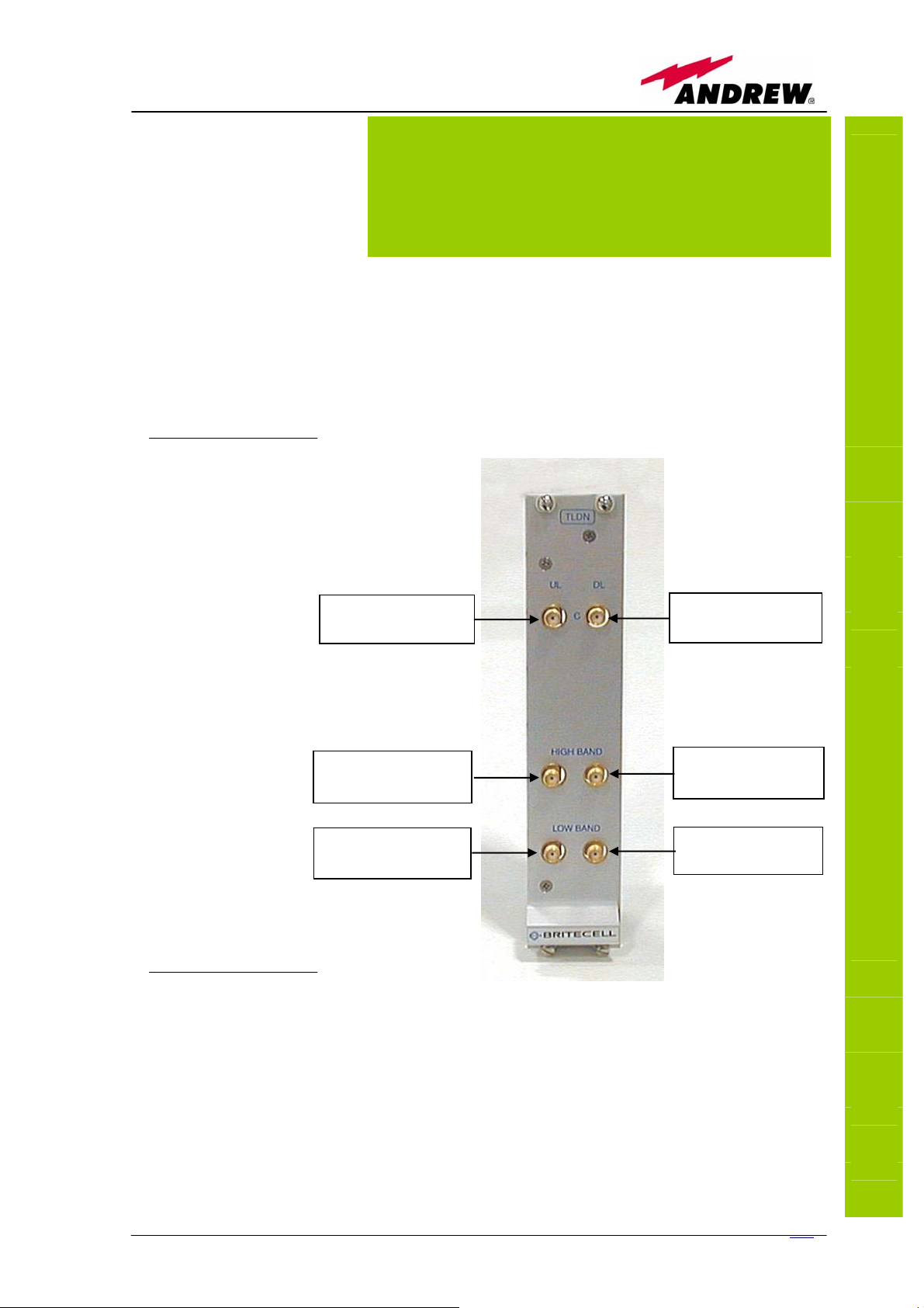
Description:
The TLDN is a passive RF
dual band coupler
designed to distribute
signal within the master
unit when coming from
different bands.
Main operations carried out are:
¾ in downlink it combines a low band RF signal (800MHz to 1000MHz) and
a high band RF signal (1700MHz to 2200MHz) into a common RF path
¾ in uplink it filters the composite signal into a low-band (800MHz to
1000MHz) and a high-band (1700MHz to 2200MHz) one.
It is a passive module.
RF dual-band coupler
TLDN
RF ports
• 1 UL common
RF input port
(“C”) for the
combined UL
signal
• 1 UL high-
band RF
UL common RF
port (SMA-f)
DL common RF
port (SMA-f)
output port
• 1 UL low-band
RF output port
• 1 DL common
RF output port
(“C”) for the
UL high-band RF
port (SMA-f)
DL high-band RF
port (SMA-f)
combined DL
signal
• 1 DL high-
band RF input
UL low-band RF
port (SMA-f)
DL low-band RF
ort (SMA-f
port
• 1 DL low-band
RF input port
TLDN main
Fig. 5.18: The TLDN dual-band coupler
applications
Main applications of the TLDN module are:
• Connecting 2 donor sources with different services to one TFLN master
optical TRX in a dual band system, so that:
¾ TLDN combines the DL inputs coming from the 2 different donor
sources (carrying different services) into an output signal entering
the TFLN master optical TRX
TLDN
MN024-08
147

¾ TLDN filters the UL input coming from a TFLN master optical TRX
into 2 UL outputs entering 2 different donor sources (carrying
different services)
TLDN insertion loss
TLDN insertion loss = 1.0 ± 0.5dB.
When designing the system, remember to take into account the insertion loss
of the TLDN.
Warnings
The overall input power must not exceed +27dBm
TLDN Installation
Since the TLDN module doesn’t require any power supply it can be housed
either in an active or a passive TPRN sub-rack.
1. Unpack the kit which include
1 TLDN
2 RF jumpers (SMA-m), 2 x 40cm
TLDN
2. Carefully insert the TLDN module in any of the TPRN sub-rack slots and
lock the 4 screws on the front corners.
3. Connect RF cables to UL and DL ports, according to what planned by
designer. Use a specific torque wrench to fix each cable to relevant ports.
148
User Manual

MN024-08
149

5.6. RF Tri band Coupler TLTN
TLTN
150
User Manual

Module name:
Description:
The TLTN is a passive RF tri
band coupler designed to
distribute signal within the
master unit when coming
from different bands.
Main operations carried out are:
¾ in downlink it combines a 800MHz to 1000MHz, a 1700MHz to 2000MHz
signal and a 2000MHz to 2200MHz signal into a single RF path
¾ in uplink it filters a composite signal into a 800MHz to 1000MHz, a
1700MHz to 2000MHz signal and a 2000MHz to 2200MHz one.
It is a passive module.
RF tri-band coupler
TLTN
RF ports
• 1 DL common RF
output port (“C”)
for the combined
DL signal
• 1 DL 2000MHz to
2200MHz RF
input port
• 1 DL 1700MHz to
2000MHz RF
input port
• 1 DL 800MHz to
1000MHz RF
input port
• 1 UL common RF
input port (“C”)
for the combined
UL signal
• 1 UL 2000MHz to
2200MHz RF
output port
• 1 UL 1700MHz to
2000MHz RF
output port
• 1 UL 800MHz to
1000MHz RF
output port
UL common RF
port (SMA-f)
UL 2000 to 2200MHz
RF port (SMA-f)
UL 1700 to 2000MHz
RF port (SMA-f)
UL 800 to 1000MHz
RF port (SMA-f)
Fig. 5.19: The TLTN tri-band coupler
DL common RF
port (SMA-f)
DL 2000 to 2200MHz
RF port (SMA-f)
DL 1700 to 2000MHz
RF port (SMA-f)
DL 800 to 1000MHz
RF port (SMA-f)
TLTN main applications
Main applications of the TLTN module are:
• Connecting 3 donor sources with different services to one TFLN master
optical TRX in a tri band system, so that:
MN024-08
151

¾ TLTN combines the DL inputs coming from 3 different donor sources
(carrying different services) into an output signal entering the TFLN
master optical TRX
¾ TLTN filters the UL input coming from the TFLN master optical TRX
into 3 UL outputs entering 3 different donor sources (carrying
different services)
TLTN insertion loss
TLTN insertion loss = 3.0 ± 0.5dB
When designing the system, remember to take into account the insertion loss
of the TLTN.
Warnings
The overall input power must not exceed +27dBm
TLTN Installation
Since the TLTN module doesn’t require any power supply it can be housed
either in an active or a passive TPRN sub-rack.
1. Unpack the kit which include
1 TLTN
2 RF jumpers (SMA-m), 2 x 40cm
TLTN
2. Carefully insert the TLTN module in any of the TPRN sub-rack slots and lock
the 4 screws on the front corners.
3. Connect RF cables to UL and DL ports, according to what planned by
designer. Use a specific torque wrench to fix each cable to relevant ports.
152
User Manual

MN024-08
153

5.7. RF Duplexer, TDPX
TDPX
154
User Manual

X
Module name:
Description:
TDPX is a frequency dependent
duplexer that combines downlink
and uplink signals while
maintaining isolation and
stability.
This board has been designed to support where the source is duplexed.
RF tri-band coupler
TDP
RF ports
• 1 DL RF output
port
• 1 UL RF input port
• 1 common RF port
(“C”) for UL and DL
combined signals
RF port for combined
UL and DL signals
TDPX main
applications
The TDPX main
application is to
connect the duplexed
antenna port of the
donor source to the
Britecell Plus system.
TDPX combines/
/splits the DL and UL
signals coming from
the donor port into
two separated ports
Fig. 5.20: The TDPX duplexer
DL RF port
UL RF port
TDPX insertion loss
The TDPX insertion losses are described in table 5.9.
TDPX UL insertion loss
TDPX DL insertion loss
When designing the system, remember to take into account the insertion
losses of the TDPX.
Table 5.9: Insertion loss values of the TDPX module
UMTS 2100MHz All other bands
2.0 ± 0.5dB 7.0 ± 0.5dB
2.0 ± 0.5dB 3.3 ± 0.5dB
MN024-08
155

Warnings
The overall input power must not exceed +30dBm.
As the module is band dependent be sure to choose the right single band
version.
TDPX Installation
Since the TDPX module doesn’t require any power supply it can be housed
either in an active or a passive TPRN sub-rack.
1. Unpack the kit which include
1 TDPX
2 RF jumpers (SMA-m), 2 x 35cm
2. Carefully insert the TDPX module in any of the TPRN sub-rack slots and
lock the 4 screws on the front corners.
3. Connect RF cables to common, UL and DL ports, according to what planned
by designer. Use a specific torque wrench to fix each cable to relevant
ports.
TDPX
156
User Manual

MN024-08
157

5.8. Base station Interface TBSI
TBSI
158
User Manual

Module name:
Description
The TBSI module adjusts
the signal level between
the donor source and the
Britecell Plus system.
It has 2 independent
variable attenuators to adjust both uplink and downlink separately (please
refer to BriteTool manual to understand how to calculate the right value of
attenuation through BriteTool software)
Base station interface
TBSI
RF ports
• 1 DL RF input port
DL RF input port (from donor source)
• 1 DL RF output port
(attenuated
signal)
DL attenuation knob
• 1 UL RF input port
• 1 UL RF output port
(attenuated signal)
DL RF output port (to master unit)
The attenuation required
both on DL and UL can be
properly set through
UL RF input port (from master unit)
relevant knobs (30dB
range, 1dB step).
UL attenuation knob
TBSI main
applications
Main applications of the
TBSI module are:
• adjusting RF levels
coming to/from a donor
source:
¾ TBSI adjusts the
DL signal to meet the required power level at TFLN DL RF input
¾ TBSI adjusts the RF UL signal coming from TFLN master optical TRX
in order to meet the desired requirements about blocking level and
receiver sensitivity to the donor source
Fig. 5.21: The TBSI base station interface
UL RF output port (to donor source)
TBSI insertion loss
The TBSI insertion losses are described in table 5.10:
TBSI insertion loss
Table 5.10: Insertion loss values of the TBSI module
800MHz to 2000MHz 2000MHz to 2200MHz
< 1dB < 1.3dB
TBSI
MN024-08
159

When designing the system, remember to take into account the insertion loss
of the TBSI.
Warnings
The overall input power must not exceed +30dBm
TBSI Installation
Since the TBSI module doesn’t require any power supply it can be housed
either in an active or a passive TPRN sub-rack.
1. Unpack the kit which include
1 TBSI
2 RF jumpers (SMA-m), 1 x 35cm, 1 x 45cm
2. Carefully insert the TBSI module in any of the TPRN sub-rack slots and
lock the 4 screws on the front corners.
3. Connect RF cables according to what planned by designer. Use a specific
torque wrench to fix each cable to relevant ports.
4. Set proper attenuation values.
TBSI
160
User Manual

MN024-08
161

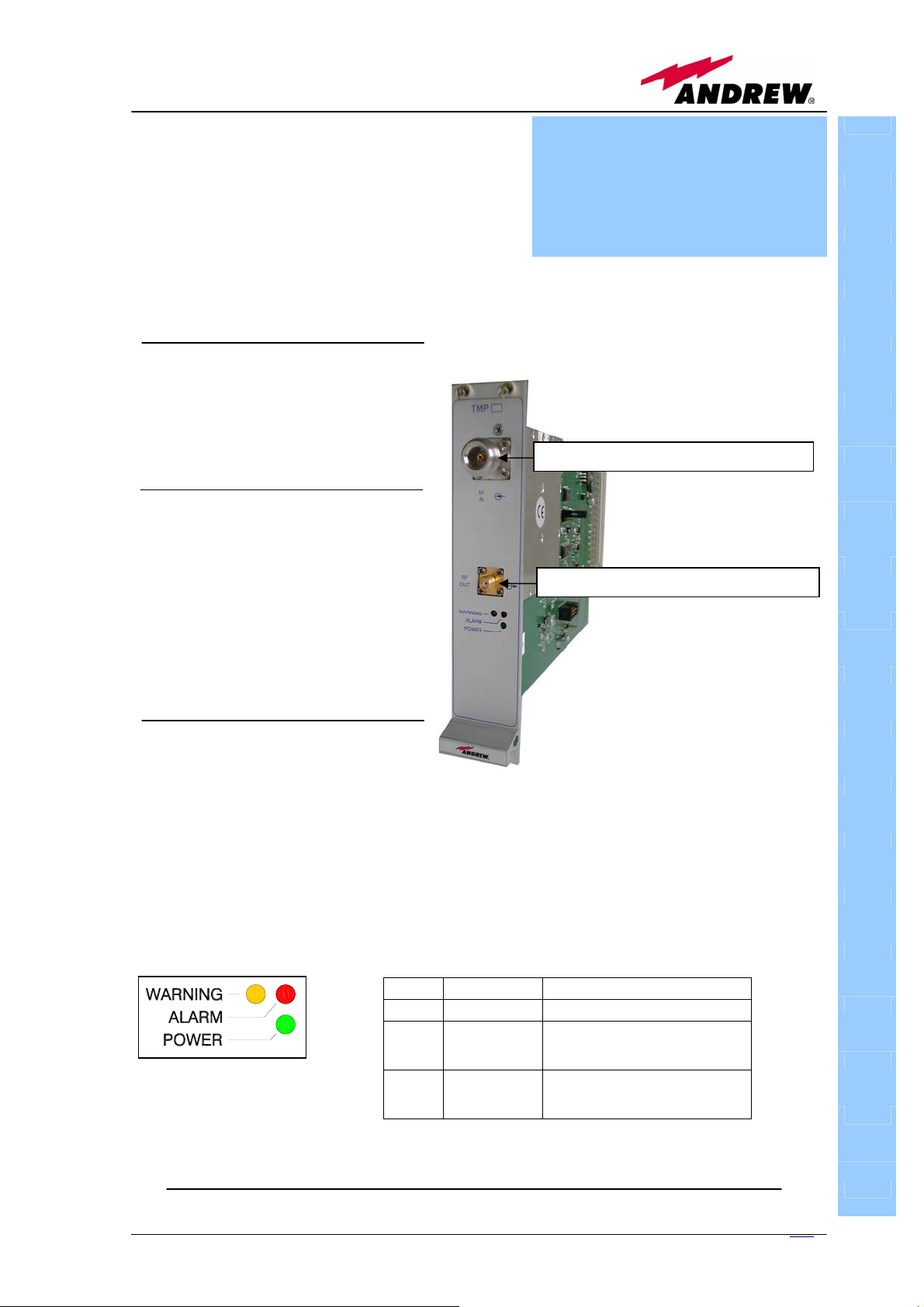
5.9. Power Limiter TMPx-10
TMPX
162
User Manual
)
)
Module name:
Description
The TMPx-10 power limiter monitors the
downlink input power and attenuates it by
10dB above a predetermined set point. The
threshold is programmable through the
supervision system.
TMPx-10 power limiter is available in two versions, one suitable for GSM DL
(800 to 1000MHz or 1800 to 2000MHz) and the other for UMTS 2100MHz DL.
Power Limiter
TMPx-10
RF ports
• 1 DL RF input port
• 1 DL RF output port
DL RF input port (from donor source
TMP main applications
Main applications of the TMP
DL RF output port (to master unit
module are:
• Check DL RF level coming from
a donor source in order to
protect the system if the level
exceeds a specified threshold.
TMP visual alarms
The TMP front panel is provided
with 3 LEDs (see on the right)
showing status and alarm information
LED meaning is reported on the rightward table.
Further information about alarm status are delivered by Britecell Plus supervision
system
Label LED colour Meaning
Power Green Power supply status OK
Alarm Red
Fig. 5.23: The LED panel
on the TMP front-side
Warning Red
Fig. 5.22: The TBSI base station interface
It can be:
- TMP power supply alarm
- RF input overdrive
It can be:
- temperature alarm
- no RF signal at the input port
Tab. 5.11: Summary of TMP LEDs meaning
TMPX
MN024-08
163

TMP power supply
Each TMPx-10 power limiter is supplied by the sub-rack back-plane (+12V).
The power consumption of each TMPx-10 is 2W max
TMP insertion loss
TMP insertion loss < 1.7dB.
When designing the system, remember to take into account the insertion loss
of the TMP.
Warnings
The overall input power must not exceed +35dBm.
Inserting or removing TMP modules
• Do not remove or insert any TMP module into TPRN sub-rack before
having switched off main power supply.
• The TMP modules must be handled with care, in order to avoid damage to
electrostatic sensitive devices.
• When installing TMP modules in the sub-rack, take care to alternate active
and passive cards in order to ensure proper heat dissipation.
• In a multi-sub-rack system, remember to assign to each sub-rack a proper
RS485 bus address before installing the modules (please refer to TPRN
section for further details).
TMP installation
The TMP power limiter can be accomodated in any of the 12 slots of a TPRN
active sub-rack.
: In case a new TMP module has to be installed in a still working Master
Note
Unit, switch off the sub-rack before inserting the plug-in TMP module
1. Unpack the kit which include
1 TMP
1 RF jumper (SMA-m), 35cm
TMPX
2. Carefully insert the TMP module in any of the TPRN sub-rack slots and
lock the 4 screws on the front corners.
3. Connect RF cables according to what planned by designer. Use a specific
torque wrench to fix each cable to relevant ports.
4. Switch on the sub-rack. As you switch on the system, carefully refer to
the TFLN Start-up section.
164
User Manual
Removing a TMP module
Switch off the Master Unit power supply and remove RF jumpers. Then
• unscrew the 4 screws and slowly remove the card.
• put the removed TMP card in its safety box.
• switch on again the Master Unit power supply and refer to TFLN Start-up
section.
TMP troubleshooting
In case a TMP power limiter has any problem, this will be easily revealed
through LEDs on its front panel otherwise troubleshooting can be carried out
through LMT or supervision system.
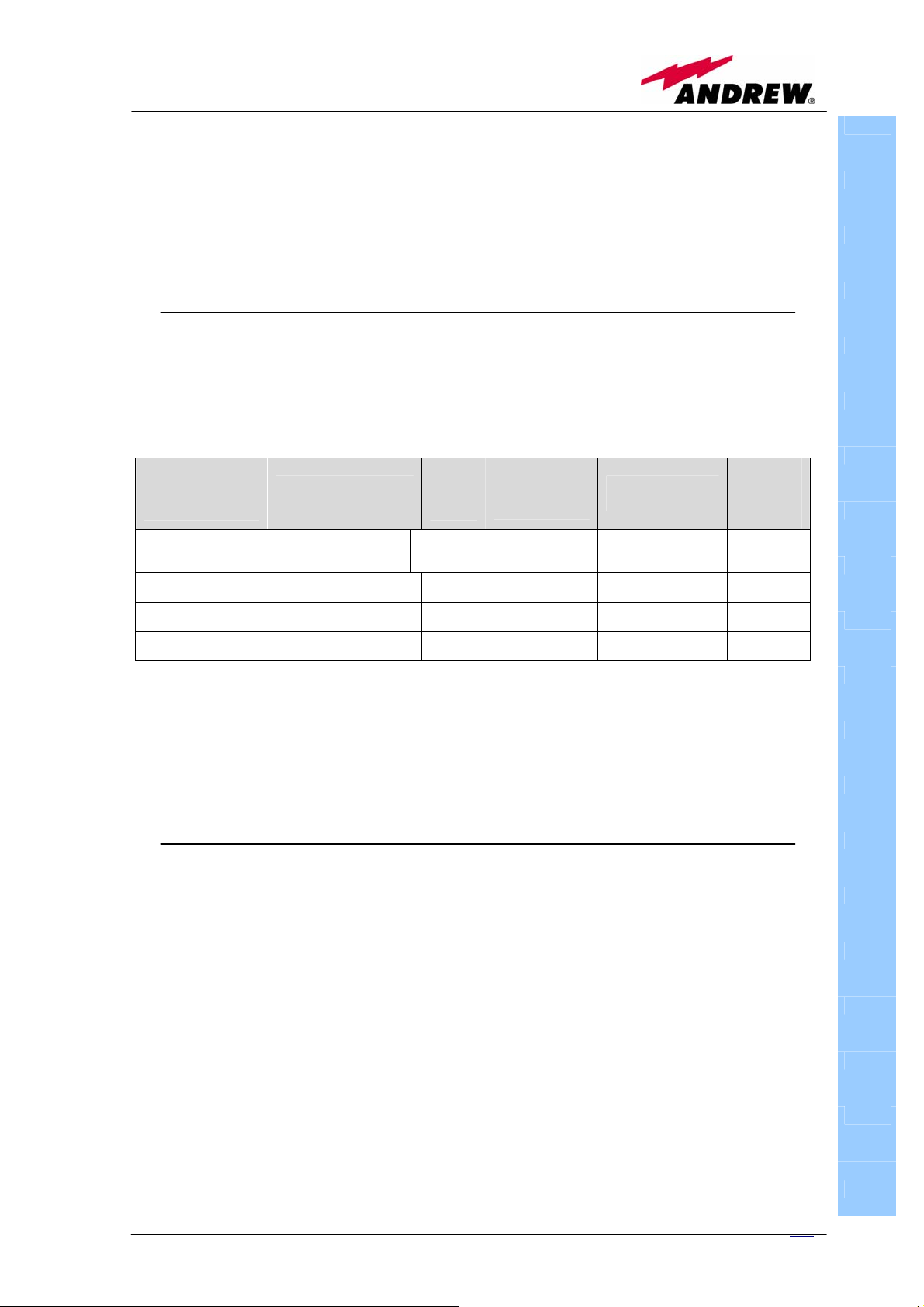
ALARM CODE
(TSUN
description)
Power supply alarm
Temperature alarm Over-temperature alarm
RF Input overdrive
RF Input No signal
ALARM
DESCRIPTION
UPS HW failure or
malfunction.
RF is turned OFF
The input signal has
exceeded the threshold
No RF signal at the input
port
ACTIV
E LED
RED MAJOR Return the unit MAJOR
YELLO
W
RED WARNING
YELLO
W
SUPERVISION
PRIORITY
LEVEL
MINOR
MINOR
ACTION
RECOMMENDED
Check ventilation
and environment
Check the RF input
signal
Check the RF input
signal
Tab. 5.12:Description of the TMP alarms
The previous table reports a brief description of the TMP alarm, together with
a reference to the corresponding alerted LEDs.
Understanding why one LED is on can be done following the troubleshooting
procedure reported hereinafter.
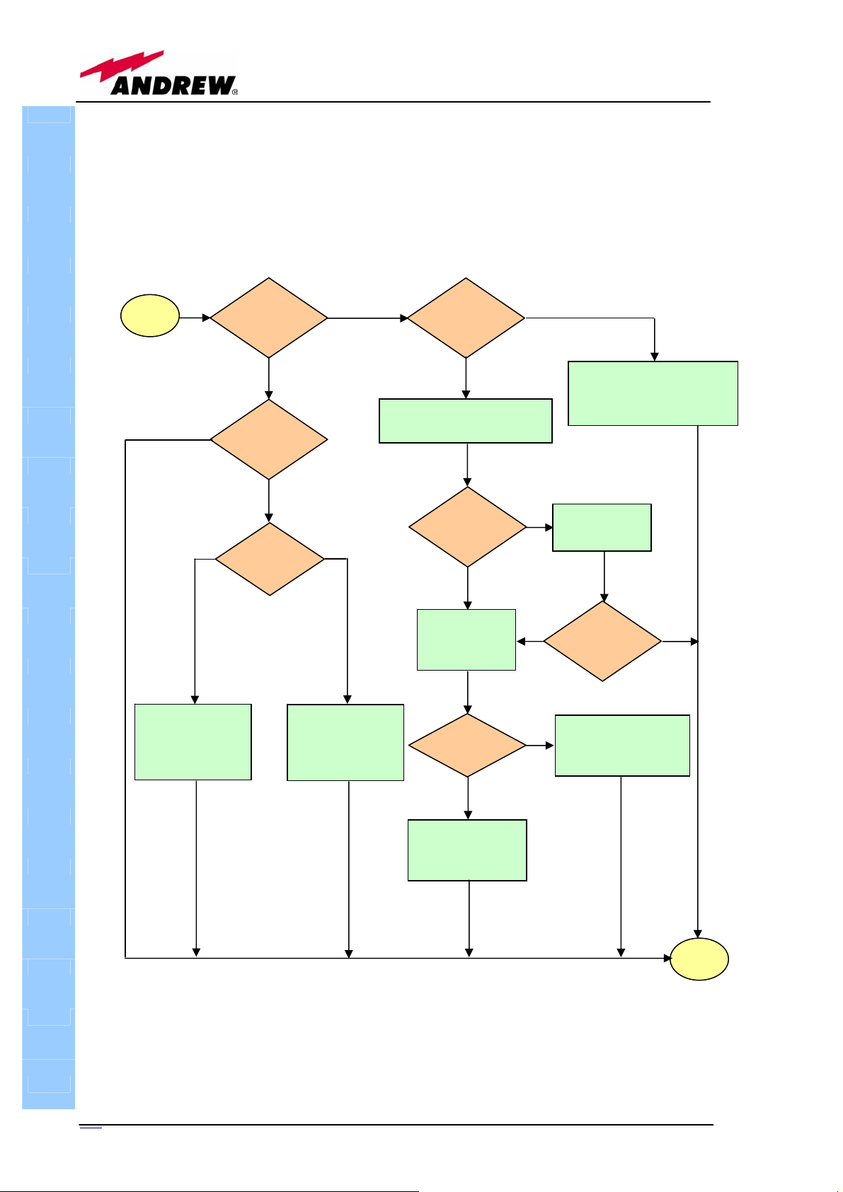
Quick troubleshooting procedure
(The following procedure is summarized by the flow-chart in fig. 22)
1. In case the TMP red led is on and the green led is off there is a problem
on the power supply.
a. Check the TPRN sub-rack and if it is switched off, switch it on.
b. If the sub-rack is switched on, check the backplane power supply
connector to verify if the +12Vdc is provided to the TMP module.
If not there is a fault on the TPRN backplane and you need to
return the sub-rack.
c. Otherwise the TMP power supply section is faulty. Return the
unit.
2. In case the TPM red and green leds are on, the RF level at the input port
has exceeded the specified threshold. Decrease the RF signal or change
the threshold.
3. In case the yellow led is on, check the RF input level
RELÉ
PRIORITY
LEVEL
(subrack)
MINOR
MAJOR
MINOR
TMPX
MN024-08
165
N
N
p
a. If there isn’t any RF signal at the input, check if the RF cable is
connected at the input port. If it’s connected check the power
coming out from the donor source.
b. Otherwise the temperature range is not within the specified
range, change the temperature range or provide proper air flow.
Is red
start
No
LED ON upon
LED ON upon
Yes
Yes
any RF input
the TMP?
No
Is yellow
the TMP?
Is there
level?
Yes
Problem on power supply
No
Is green
LED OFF upon
the TMP?
Yes
Is
TPRN sub-rack
switched on?
Yes
Check TPRN
backplane
power supply
No
No
o
RF level @ input port has
exceeded the threshold.
Check the RF signal.
Switch on
the sub-rack
Is red
LED ON and
green OFF?
Yes
TMPX
Check if the
temperature is
within the
s
ecified range.
Fig. 5.24: Flow-chart describing the troubleshooting procedure
Check the RF
input level and
if the RF cable
is connected
Is +12Vdc
provided?
o
TPRN backplane
is faulty. Return
the TPRN
No
TMP power supply
section is faulty.
Return the TMP.
end
166
User Manual

MN024-08
167

TWLI
5.10. Wi-Fi Local Interface, TWLI
168
User Manual
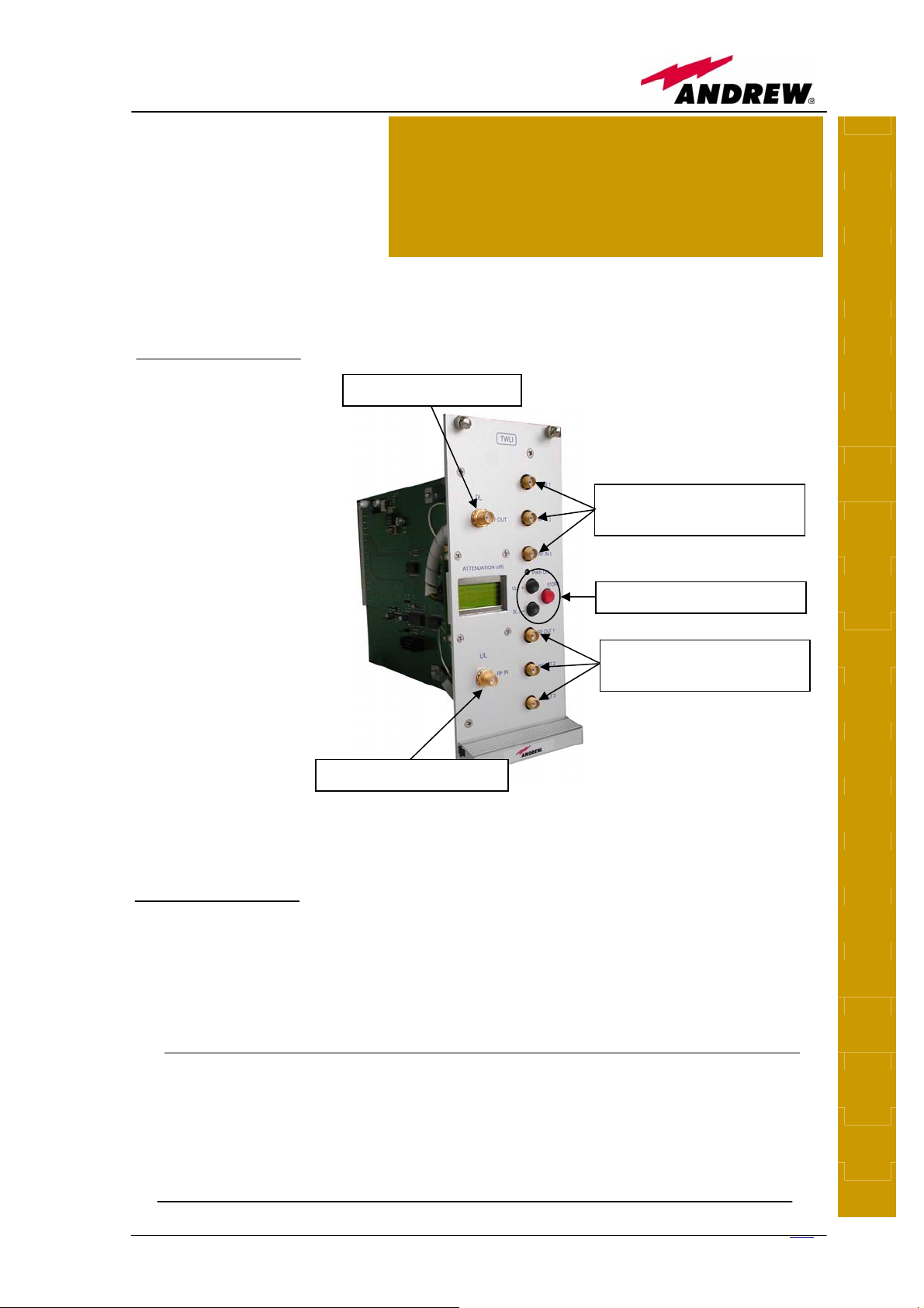
Module name:
Description
Britecell Plus system allows
distributing WLAN service
(802.11b and g) through
the auxiliary channel while
concentrating all the Access
Points together with the central equipment.
The TWLI module allows connecting up to 3 Access Points to one TFLN master
optical TRX and setting up to 4dB attenuation, if needed, on the DL path.
RF ports
• 3 DL RF input
ports receiving
signals from
up to 3
different
Access Points
• 1 DL RF
output port to
the TFLN
auxiliary port
• 1 UL RF input
port from the
TFLN auxiliary
port
• 3 UL RF output
ports sending
signals to up
to 3 different
Access Points
4dB attenuation range is available on the DL path in order to adjust levels
coming from the Access Points.
DL RF output to TFLN
UL RF input from TFLN
Wi-Fi Local Interface
TWLI
DL RF input
from Access Points 1 to 3
Attenuation setting buttons
UL RF output
to Access Points 1 to 3
Fig. 5.25: The TWLI wi-fi
local interface
TWLI main applications
Main applications of the TWLI module are:
• providing to the TFLN the WLAN signals coming from up to 3 Access Points
concentrated on the equipment room.
TWLI power supply
Each TWLI WLAN interface module is supplied by the sub-rack back-plane
(+12V).
The power consumption of each TWLI is 2W max.
TWLI
MN024-08
169

TWLI
Warnings
The overall input power must not exceed +19dBm
The TWLI modules must be handled with care, in order to avoid damage to
electrostatic sensitive devices.
Inserting or removing TWLI modules
• Do not remove or insert any TWLI module into TPRN sub-rack before
having switched off main power supply.
• The TWLI modules must be handled with care, in order to avoid damage to
electrostatic sensitive devices.
• When installing TWLI modules in the sub-rack, take care to alternate
active and passive cards in order to ensure proper heat dissipation.
• In a multi-sub-rack system, remember to assign to each sub-rack a proper
RS485 bus address before installing the modules (please refer to TPRN
section for further details).
TWLI installation
The TWLI WLAN local interface can be accomodated in any of the 12 slots of a
TPRN active sub-rack.
: In case a new TWLI module has to be installe d in a still working M aster
Note
Unit, switch off the sub-rack before inserting the plug-in TWLI module
1. Unpack the kit which include
1 TWLI
2 RF jumpers (SMA-m; SMB-f), 2 x 40cm
2. Carefully insert the TWLI module in any of the TPRN sub-rack slots and
lock the 4 screws on the front corners.
3. Connect RF cables according to what planned by designer. Use a specific
torque wrench to fix each cable to relevant ports.
4. Switch on the sub-rack. As you switch on the system, carefully refer to
the TFLN Start-up section.
Removing a TWLI module
Switch off the Master Unit power supply and remove RF jumpers. Then
• unscrew the 4 screws and slowly remove the card.
• put the removed TWLI card in its safety box.
• switch on again the Master Unit power supply and refer to TFLN Start-up
section.
170
User Manual

MN024-08
171

TILx
(intro)
5.11. Interconnect Link (i-link)
172
User Manual

W
(b)
(b)
Module name:
5.11.1. Introduction
Interconnect link
the interconnect link is a set of
modules which allows to expand the
system by connecting a second
Britecell Plus subrack station to the
main one, at a distance of up to 20
km. By using more interconnect links at the main station, more Britecell Plus
stations could be connected to the main one, in a star configuration.
Each interconnect link (i-link) is made up by a master-side and by a slaveside. Both the master side and the slave side are composed by a receiver
module and by a transmitter module (please refer to fig. 5.26, 5.27): the
transmitter modules are identified by the code TDTX, while the receiver
module is identified as TMRX at the master side and as TSRX at the slave side.
The interconnect link is available both in simple version (identified as TILx-HL)
and in WDM version (identified as TILx-HLW). A WDM i-link exploits the same
fibre to transmit both from master to slave and vice-versa (please refer to fig.
5.28b), while the simple link uses a dedicate fiber for the transmission from
master to slave, and a different one for the transmission from slave to master
(please refer to fig. 5.28a).
The following four section will describe in details the i-link modules both in
WDM and not-WDM version.
t
(a)
(a)
Fig. 5.26: i-link modules: (a)
master side; (b) slave-side.
Fig. 5.27: WDM i-link modules:
(a) master side; (b) slave-side.
TILx-HL
TILx-HL
TILx
(intro)
MN024-08
173

TILx
(intro)
GSM
900
BTS
GSM
1800
BTS
UMTS
BTS
Fixed
Atten
Fixe
d
Fixed
Atten
BTS
INTERFACING
SECTION
+
SPLITTING -
COMBINING
SECTION
TFLN
TFLN
TMRX
TFAx
TFAx
TFAx
TFAx
TDTX
TFAx
TFAx
TFAx
TFAx
TFLN
TFLN
TFAx
TFAx
TFAx
TFAx
TFAx
TFAx
TFAx
TFAx
Fig. 5.28(a): Block scheme of a Britecell Plus system with a simple i-link
174
User Manual

GSM
900
BTS
GSM
1800
BTS
UMTS
BTS
Fixed
Atten
Fixe
d
Fixed
Atten
BTS
INTERFACING
SECTION
+
SPLITTING -
COMBINING
SECTION
TFLN
TFLN
TMRX
TDTX
TFAx
TFAx
TFAx
TFAx
TDTX
TSRX
TFAx
TFAx
TFAx
TFAx
TFLN
TFLN
TFAx
TFAx
TFAx
TFAx
TFAx
TFAx
TFAx
TFAx
TILx
(intro)
Fig. 5.28(b): Block scheme of a Britecell Plus system with a WDM i-link
MN024-08
175

TILx
(intro)
176
User Manual
x
5.11.2. TILx-HL i-link
Interconnect link
Module description:
The TILx interconnect link is a composite module, made up by a transmitter
and a receiver module both on master and on slave side:
• Master side
- TDTX 300 (transmitter module, hosted by 1 subrack slot)
- TMRX 200 (receiver module, hosted by 1 subrack slot)
• Slave side
- TDTX 300 (transmitter module, hosted by 1 subrack slot)
- TSRX 2xx/8 (receiver module, hosted by 3 subrack slots)
The TILx – HL kit is available in EU tri-band version (EGSM 900MHz, GSM
1800MHz, UMTS), in US dual-band version (SMR 800MHz & Cellular 800MHz,
PCS 1900 MHz), and in hybrid version (SMR 800MHz & Cellular 800MHz, GSM
1800MHz, UMTS). These versions just differs in the slave-side receiver TSRX
module, which is the only module whose features vary with the RF
transmitting band.
Module name:
TIL
-HL
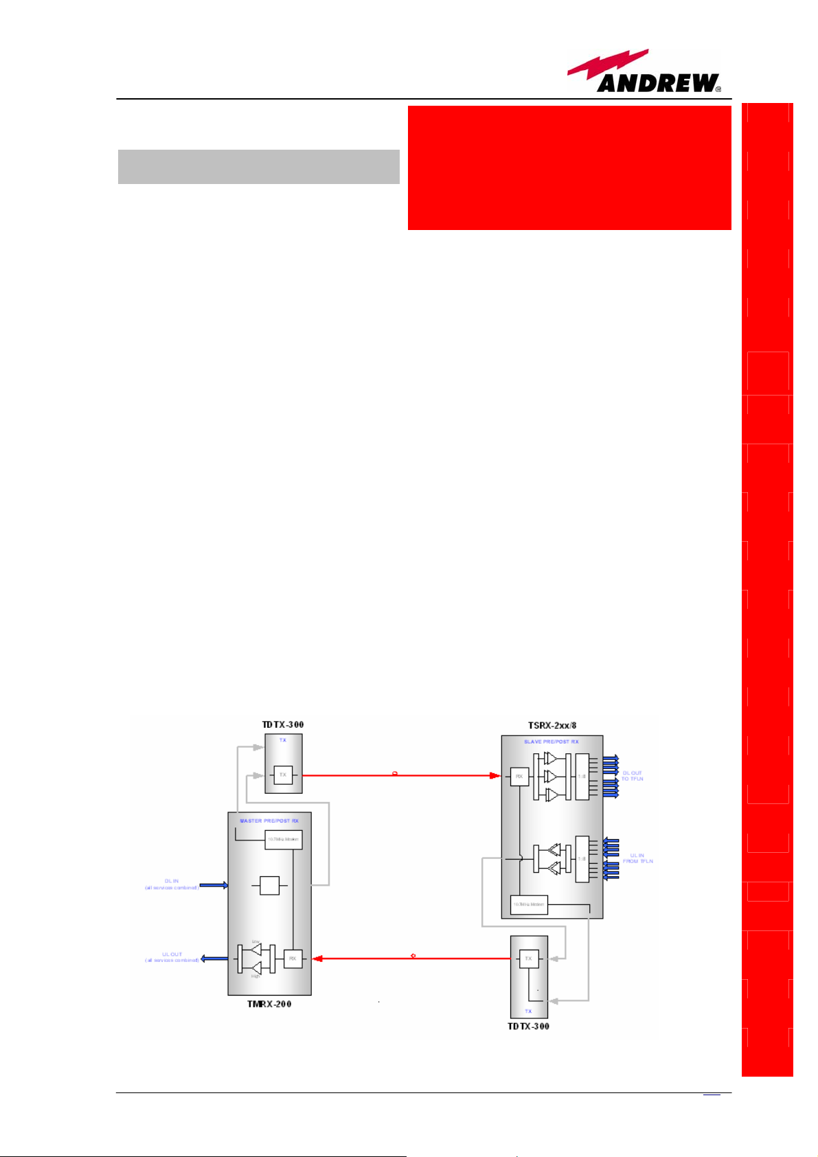
Block scheme
A scheme of the system, is reported hereinafter, so as describe the
connections between the Interconnect-link modules and to give an insight of
the function of the modules named above.
Fig.5.29 – Interconnect link scheme
TILx-
-HL
MN024-08
177

M
TILx-
-HL
Main TILx-HL functions:
Downlink:
Master side:
Slave side
Uplink:
aster side:
Slave side:
• RF-to-Optical conversion of the signal coming from the
splitting/combining section, and transmission to the slave
i-link modules via fiberoptics cable;
• Modulation and RF-to-Optical conversion of the bus
information, and transmission to the slave i-link modules
via fiberoptics cable (on 1310 nm wavelength);
• Optical-to-RF conversion of signal and alarm information,
with Automatic Gain Control (AGC) in order to
compensate the optical losses;
• Distribution of the RF signal to the TFLN optical TRXs, and
demodulation of the bus information
• Optical-to-RF conversion of signal and alarm information,
with Automatic Gain Control (AGC) in order to
compensate optical losses
• Distribution of the RF signal to the splitting/combining
section, and demodulation of the alarm information
• RF-to-Optical conversion of the signal coming from the
TFLN optical TRXs, and transmission to the master i-link
modules via fiberoptics cable;
• Modulation and RF-to-Optical conversion of the alarm
information, and transmission to the master i-link
modules via fiberoptics cable (on 1310 nm wavelength);
178
User Manual
(
(
(
m
m
)
r
(
p
p
)
j
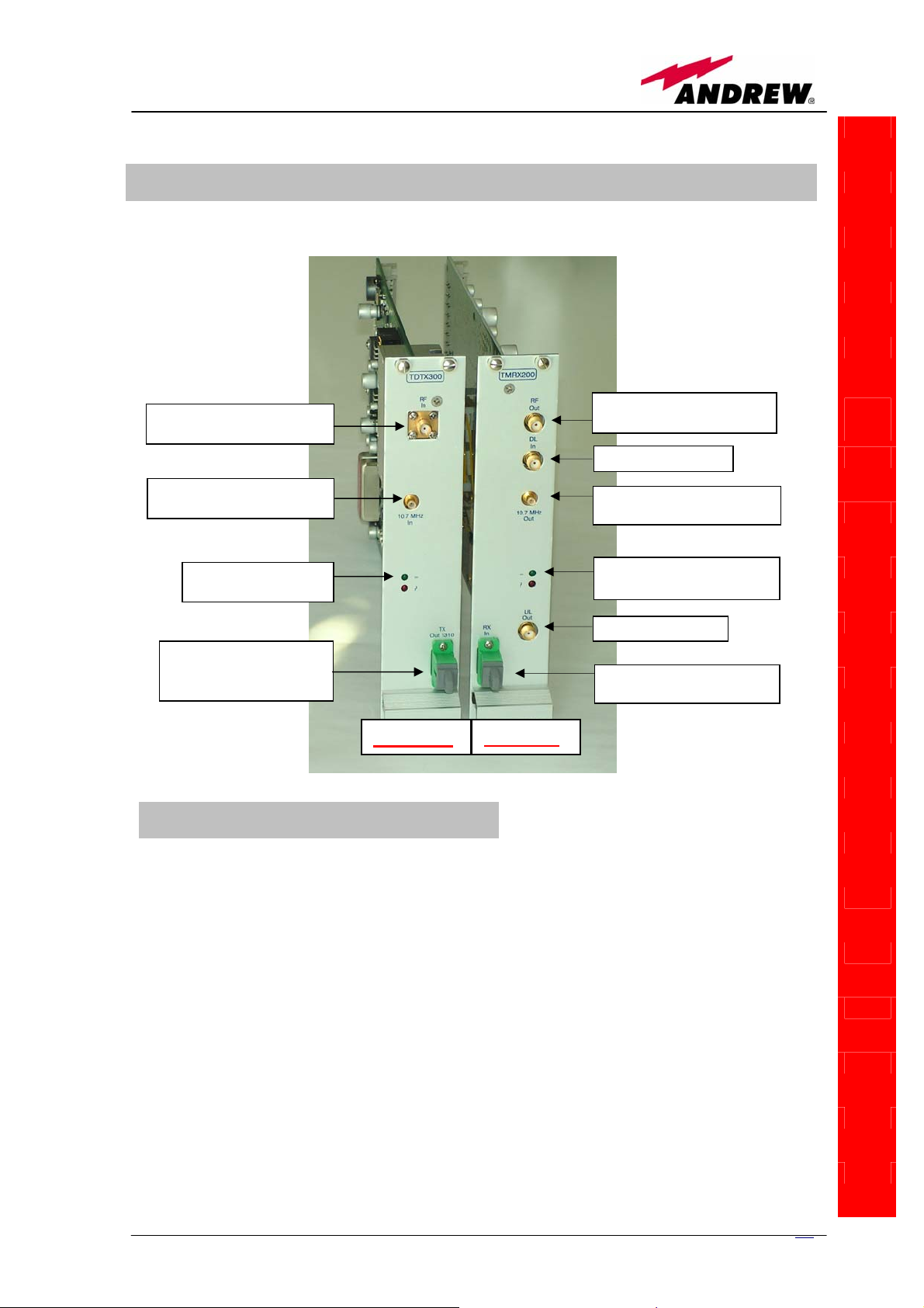
TILx-HL Master Side: TDTX300 transmitter + TMRX200 receiver
Fig.5.30 – The i-link
master side is made up
by a TDTX300
transmitter and by a
TMRX200 receiver
RF in port connected to
TMRX200 master
SMA-f)
RF out port connected to
TDTX300 maste
DL RF
SMA-f)
ort (SMA-f
Alarm in port connected to
TMRX200 master
SMB-m)
Alarm out port connected to
TDTX300
aster (SMB-
GREEN LED: power on
RED LED: ma
or alarm
GREEN LED: power on
RED LED: major alarm
Optical out port connected to
TSRX 2xx/8 slave(SC-APC)
UL RF
ort (SMA-f)
Optical in port connected to
TDTX300 slave
SC-APC)
TDTX300
TILx – HL Master-side: RF ports
TDTX300 transmitter:
¾ 1 RF input port , to be connected directly to the
RF output port of the TMRX200 adjacent module
¾ 1 alarm input port, to be connected directly to
the alarm output port of the TMRX200 adjacent
module
TMRX200 receiver:
¾ 1 RF output port, to be connected directly to the
RF input port of the TDTX300 adjacent module
¾ 1 alarm output port, to be connected directly to
the alarm input port of the TDTX300 adjacent
module
¾ 1 RF DL port, sent to the passive devices which
interface the Britecell with the BTS
¾ 1 RF UL port, coming from the passive devices
which interface the Britecell with the BTS
TMRX20
TILx-
-HL
MN024-08
179

/
TILx-
-HL
TILx – HL Master-side: Optical ports
T
DTX300 transmitter:
¾ 1 Optical output port, to be connected directly
to the optical input port of the slave-side
TSRX2xx
8 receiver
TMRX200 receiver:
¾ 1 Optical input port, to be connected directly to
the optical output port of the slave-side TDTX300
transmitter
TILx – HL Master-side: LED Alarms
TDTX300 transmitter
:
Two control LEDs (one green, one red) are placed on
the TDTX300 front panel. The green LED describes
the power supply status of the TDTX module, while
the red LED describes the major TDTX failure (please
refer to table 5.13)
TMRX200 receiver:
Led colour
Red
Green Power supply OK
Two control LEDs (one green, one red) are placed on
the TMRX200 front panel. The green LED describes the
power supply status of the TDTX module, while the red
LED describes the major TMRX failure (please refer to
table 5.14)
Meaning
Optical power failure, wavelength out of
range, power supply failure
Table 5.13: Summary of master TDTX300 LEDs meaning
Led colour
Red
Green Power supply OK
Meaning
Power supply failure, modem failure, RF UL
failure, AGC compensation failure
Table 5.14: Summary of TMRX200 LEDs meaning
180
User Manual
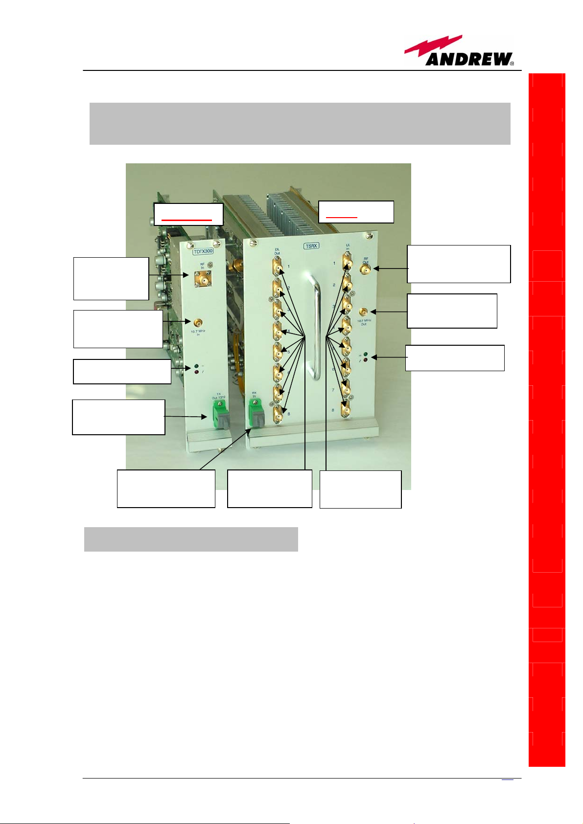
(
(
j
m
TILx - HL Slave-Side:
TDTX300 transmitter + TSRX2xx/8 receiver
TDTX300
TSRX
RF in port
connected to
TSRX2xx/8 slave
SMA-f)
Alarm in port
connected to slave
TSRX2xx/8 (SMB-m)
GREEN LED: power on
RED LED:ma
or alarm
Optical out port ,
connected to TMRX200 master (SC-APC)
Optical in port,
connected to TDTX-300
master (SC-APC)
DL RF ports
connected to TFLN
DL ports (SMA-f)
UL RF ports
connected to TFLN
UL ports (SMA-f)
TILx – HL Slave-side: RF ports
TDTX300 transmitter:
¾ 1 RF input port , to be connected directly to the
RF output port of the TSRX2xx/8 adjacent
module
¾ 1 alarm input port, to be connected directly to
the alarm output port of the TSRX2xx/8
TSRX2xx/8 receiver
¾ 1 RF output port, to be connected directly to the
RF input port of the TDTX300 adjacent module
¾ 1 alarm output port, to be connected directly to
the alarm input port of the TDTX300 adjacent
module
¾ 8 RF DL ports, which can feed up to 8 TFLN local
transmitters ;
¾ 8 RF UL ports, which can receive the UL signals
from up to 8 TFLN local transmitters.
Fig.5.31 – The i-link
master side is made
up by a TDTX300
transmitter and by a
TMRX200 receiver
RF out port, connected to
TDTX300 master (SMA-f)
Alarm out port
connected to master
TDTX300
GREEN LED: power on
RED LED:major alar
SMB-m)
TILx-
-HL
MN024-08
181

TILx-
-HL
TILx -HL Slave-side: Optical ports
TDTX 300 transmitter:
TSRX2xx/8 receiver:
¾ 1 Optical output port, to be connected directly
to the optical input port of the master-side
TMRX200 receiver
¾ 1 Optical input port, to be connected directly
to the optical output port of the master-side
TDTX300 transmitter
TILx – HL Slave-side: LED Alarms
TDTX300 transmitter:
TSRX2xx/8 receiver:
Led colour
Red
Green Power supply OK
Table 5.15: Summary of slave TDTX300 LEDs meaning
Led colour
Red
Green Power supply OK
Table 5.16: Summary of TSRX2xx/8 LEDs meaning
Two control LEDs (one green, one red) are placed
on the TDTX300 front panel. The green LED
describes the power supply status of the TDTX
module, while the red LED describes the major
Two control LEDs (one green, one red) are placed
on the TSRX2xx/8 front panel. The green LED
describes the power supply status of the TSRX
module, while the red LED describes the major
TSRX failure.
Meaning
Optical power failure, wavelength out of
range, power supply failure
Meaning
Power supply failure, modem failure, RF UL
and DL failure, AGC compensation failure
182
User Manual

Warnings (to be read before the TILx – HL installation)
Dealing with optical output ports
• The TDTX modules (both on master and on slave side) contain
semiconductor lasers. Invisible laser beams may be emitted from the
optical output ports. Do not look towards the optical ports while equipment
is switched on.
Handling optical connections
• When inserting an optical connector, take care to handle it so smoothly
that the optical fibre is not damaged. Optical fibres have to be single-mode
(SM) 9.5/125µm.
• Typically, Britecell Plus equipment is provided with SC-APC optical
connectors. Inserting any other connector will result in severe damages.
• Do not force or stretch the fibre pigtail with radius of curvature less than 5
cm.
• Remove adapter caps only just before making connections. Do not leave
SC-APC adapters open, as they attract dust. Unused SC-APC adapters must
always be covered with their caps.
• Do not touch the adapter tip. Clean it with a proper tissue before inserting
each connector into the sleeve. In case adapter tips need to be better
cleaned, use pure ethyl alcohol
Inserting or removing TDTX, TMRX, TSRX modules
• Do not remove or insert any module into TPRN sub-rack before having
switched off main power supply.
• Modules must be handled with care, in order to avoid damage to
electrostatic sensitive devices.
• When installing the modules in the sub-rack, take care to alternate active
and passive cards in order to ensure proper heat dissipation.
• In a multi-sub-rack system, remember to assign to each sub-rack a proper
RS485 bus address before installing the modules (please refer to TPRN
section for further details).
Placing the TILx -HL modules inside the subrack
• The i-link modules at slave side should be installed in the middle of the
slave subrack, or at least they should have no more than 4 TFLN modules
both on the right side and on the left side of the TSRX
requirement is advised in order to allow connection between the TSRX
module and all the TFLN transmitters (see fig. 5.33)
2xx/8 module. This
TILx – HL installation
Master Cable Installation Kit:
• 1 SMA-Male/SMA-Male RF jumpers
• 1 SMB-Female/SMB-Female RF jumper
Both on master side and on slave side, the i-link modules are to be housed
into a TPRN active sub-rack.
Slave Cable Installation Kit:
• 17 SMA-Male/SMA-Male RF jumpers
• 1 SMB-Female/SMB-Female RF jumper
TILx-
-HL
MN024-08
183
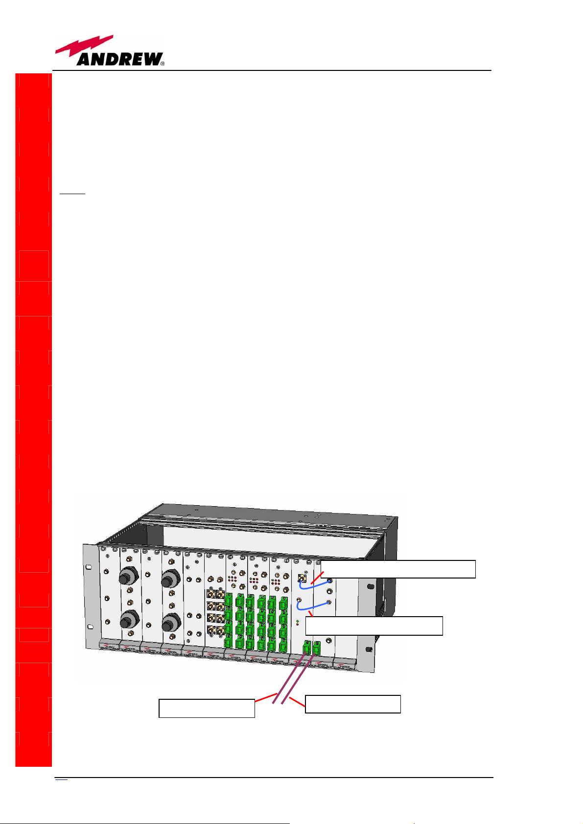
RF jump
(
S
)
TILx-
-HL
On the master-side station, the i-link modules are to be housed into 2
adjiacent slots, chosen among the 12 available ones in the subrack.
On the slave-side subrack, the i-link modules are to be housed into 4
adjiacent slots: moreover, due to the particular cabling they require, these 4
adjiacent slots should be placed in mid-subrack, so that no more than 4 TFLN
local units stay on each side of the i-link modules (as shown in fig. 5.33).
: If the i-link modules are to be installed in an already working Master
Note
Unit, switch off the sub-racks before inserting the modules.
Before inserting the boards into the TPRNx4 subracks, make sure to set
proper RS485 addresses. A basic rule of the Britecell installation is that 2
subracks belonging to the same Master Unit should always have different
RS485 addresses (please refer to “TPRN Installation” section): since the
interconnect-link basically provides an extension of the Master Unit bus, any
subrack on the i-link master-side should also have a RS485 address different
from any subrack on the i-link slave side.
Please refer to “TPRNx4 Installation” section for more information on setting
the RS485 address.
Firstly, carefully insert the TMRX200 and the TDTX300 boards in 2 adjacent
slots of the Master side subrack. Lock the 4 screws on the corners of each
boards.
Use the provided SMA-m RF jumper in order to connect the RF Out Port of the
TMRX200 module to the RF In Port of the adjacent TDTX300 module. Use the
SMB-f jumper to connect the 10.7MHz ports of the two boards. Fix these RF
jumpers to the RF ports through a proper torque wrench (not included).
Remove the protection cap from the optical ports of the 2 modules on the
master side.
Take a SC-APC fiber, clean the fibre termination, and connect it to the optical
er
MA-m / SMA-m
RF jumper (SMB-f / SMB-f)
Fig. 5.32: TILx-HL master side
184
User Manual
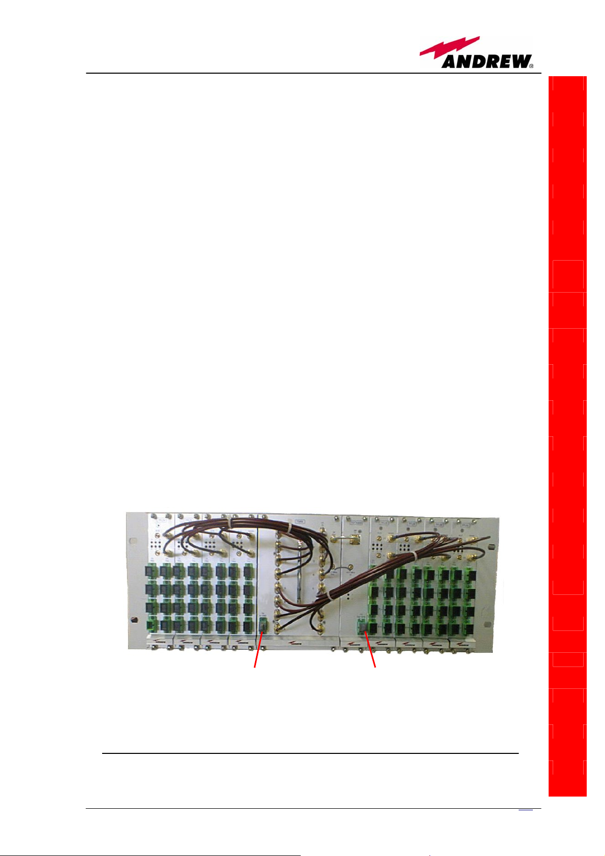
out port of the master-side TDTX300 module. (This fiber shall be directly
connected to the optical in port of the TSRX2xx/8 module on the slave-side
subrack)
Take a SC-APC fiber, clean the fibre termination, and connect it to the optical
in port of the TMRX200 module (This fiber shall be directly connected to the
optical out port of the TDTX300 on the slave-side subrack)
Carefully insert the TSRX2xx/8 and the TDTX300 boards in 4 adjacent slots of
the Master side subrack. As already explained, take care not to have more
than 4 TFLN modules on each side of the i-link pieces. Lock the 4 screws on
the corners of each boards.
Use the provided SMA-m RF jumper in order to connect the RF Out Port of the
TSRX2xx/8 module to the RF In Port of the adjacent TDTX300 module. Use the
SMB-f jumper to connect the 10.7MHz ports of the two boards.
Use the longer RF jumpers (included) to connect each pair of TSRX UL and DL
ports to the corresponding UL and DL ports of each TFLN module mounted on
slave-side subrack. If less than 8 TFLNs are used at slave-side, make sure to
mask the TSRX-2xx/8 unused DL and UL ports by SMA loads (not provided).
Remove the protection cap from the optical ports of the 2 modules on the
slave side.
Take a SC-APC fibre, clean the fibre termination, and connect it to the optical
out port of the master-side TDTX300 module. This fiber has to be directly
connected to the optical in port of the TMRX200 module of the master-side
subrack. Use a specific torque wrench to fix the RF cables to the RF ports.
Take a SC-APC fiber, clean the fibre termination, and connect it to the optical
in port of the TSRX200 module. This fiber has to be directly connected to the
optical out port of the TDTX300 on the master-side subrack.
As you switch on the system, carefully refer to the “TILx-HL start-up” section.
DL optical cable UL optical cable
Fig. 5.33: TILx-HL slave side
TILx-
-HL
MN024-08
185

6
TILx-
-HL
Removing a TILx - HL module
To remove an i-link module, firstly switch off the TPRNx4 subrack which
houses the module.
Remove the fibers and the RF jumpers connected to the i-link module which is
going to be removed. Insert the caps on the optical ports which has just been
disconnected.
Unscrew the 4 screws at the corners of the i-link module which is going to
removed, and slowly remove the card.
Put the card in its safety box
TILx – HL start-up
Before both the master-side station and the slave-side station(s) are switched
on, make sure that:
• all expected modules have been inserted into the Master Unit
• the modules have been connected each other by RF jumpers, according to
what planned in the system design
• the i-link master modules have been connected to the relevant slave side
modules through fiberoptics cables;
• every TFLN master optical TRX has been connected to relevant remote
units
• each remote unit has been connected to its coverage antennas
• the remote supervision unit, if present, has been connected to the Master
Unit
• both on the master-side and on slave-side stations, the different subracks
are connected each other via bus RS485
After that, remember that all remote units have to be switched on before the
master-side and the slave-side subracks. When all the remote units are on,
the different subracks (at master-side and slave-side) can be switched on.
Once all the active subracks have been switched on, the behaviour of the
different i-link modules can be summarized as follows:
o All the LEDs on the different i-link modules (both on master side and on
slave side) turn on for a couple of seconds;
o After that, all the green LEDs on the different modules remain ON (thus
indicating proper power supply), while the red LEDs switch off as soon as
the master-side and the slave-side detect each other;
o During normal working operations, the LEDs on the front panels of the
TILx modules should behave according to what described in table 5.13,
5.14, 5.15, 5.16;
o Once all the master-side and slave-side subracks have been switched
on, the system should begin to work correctly. Anyway, in order that the
i-link modules are recognized by the supervision management system, it
is necessary that the system carries out the discovery phase (please
refer to Supervision System Manual for more details). During this phase,
18
User Manual

7
whose duration depends on the system complexity and which can last at
max. 4min, the TFLN LEDs ┌┘ blink. Do not connect/disconnect any
cable or any piece of equipment during the discovery phase! This
may result in failing the identification of some equipment.
Note: in case discovery doesn’t start automatically, check through the
LMT or the remote supervision whether it has been disabled (refer to
LMT or remote supervision system manuals for further information).
o Finally, please note that the receiver module TSRX2xx/8 has only one
connection with the subrack backplane, so that the LMT software and the
supervision system will detect it as a 1-slot card. More in details, only the
slot which hosts the TSRX LED alarms is recognized by LMT or
supervision. The other 2 slots hosting the TSRX receiver are therefore to
be masked through the LMT or the Supervision System Interface (please
refer to the relevant user manuals) in order to avoid fictitious alarm
notifications.
TILx – HL troubleshooting
Faults on the i-link modules can be revealed:
• by LEDs on the front panels of the modules themselves
• by the LMT software running on a PC connected to a master side or a slave-
side subrack via RS232 port;
• by the supervision system interface managed by the remote supervision
unit, usually placed conveniently on the master-side.
Both LMT and supervision system provide full information about the device
causing the alarm. As a consequence, troubleshooting procedure can be very
immediate when failure detection is directly carried out through LMT or
supervision system.
The tables 5.17, 5.18, 5.19 reports a brief description of alarm related to the
different i-link modules, together with a reference to corresponding alerted
LEDs and to possible recovery actions.
As shown by these tables, the LEDs show only the alarms concerning the
board where they are housed: so, a red LED which is switched on at TSRX
front side reveals an alarm affecting the TSRX module itself (it does not deals
with the alarms affecting the other module of the i-link slave-side, which is an
TDTX300, and whose alarms will be detected by its own LEDs). Moreover,
these tables show that the LEDs reveals only major alarms, whereas the minor
alarms (i.e. the low priority ones) are revealed only by the LMT software or
through the TSUN supervision system. The minor alarms usually detect critical
situations which should be checked so as to avoid future possibile system
faults.
Although any alarm detected by a LED on the i-link modules should be verified
through LMT or supervision software when an accurate check is needed, some
ordinary maintenance procedures could be carried out quickly following the
instructions described hereinafter
TILx-
-HL
MN024-08
18

TILx-
-HL
TDTX 300 (master side or slave side)
ALARM
CODE
(TSUN
description)
Vcc alarm
Optical power
<1dB
Optical power
<3dB
Temperature
Alarm
ALARM
DESCRIPTION
There is a degradation on
the power supply provided
by the backplane
The received optical power
experiences a degradation
which is near to the AGC
working threshold (but it
can still compensate
losses)
The transmitted optical
power experiences a
degradation which can no
more be compensated by
the AGC.
Over-temperature alarm
(lower than 0° C or higher
than 65° C)
Table 5.17: Description of TDTX300 alarms, as they are described by the LMT
software or by the suspervision interface
ACTIVE
LED
RED MAJOR Return the unit MAJOR
NONE MINOR
RED MINOR Return the unit MAJOR
NONE WARNING
SUPERVISION
PRIORITY
LEVEL
RECOMMENDED
Check the optical loss /
AGC status on the
TSRX or TMRX
module at the other
imterconnect link
Check the subracks
ventilation; verify the
environmental
conditions involving
heating and air
ACTION
side of the
circulation
RELÉ
PRIORITY
LEVEL
(subrack)
MINOR
MINOR
188
User Manual

ALARM
CODE
(TSUN
description)
Power supply
alarm
RX1 AGC out
of range
RX1 Optical
power fail
Temperature
alarm
FSK modem
alarm
ALARM
DESCRIPTION
There is a degradation
in power supply
distribution
The received optical
power experiences a
degradation which is
near to the AGC
working threshold (but
it can still compensate
losses)
The transmitted
optical power
experiences a
degradation which can
no more be
compensated by the
AGC
Over-temperature
alarm
HW problem on the
10.7 MHz FSK
modem
TMRX 200
ACTIVE
LED
RED MAJOR Return the unit MAJOR
NONE WARNING
RED MAJOR Return the unit MAJOR
NONE WARNING
RED CRITICAL Return the unit MAJOR
SUPERVISION
PRIORITY
LEVEL
ACTION
RECOMMENDED
Check the optical loss
/ AGC status on the
TSRX or TMRX
module at the other
side of the
imterconnect link
Check the subrack
and cabinet
ventilation, verify the
environmental
conditions involving
heating and air
circulation
RELÉ
PRIORITY
LEVEL
(subrack)
MINOR
MINOR
TILx-
-HL
UL RF alarm UL hardware failure RED MAJOR Return the unit MAJOR
Current Fail Overcurrent alarm RED MAJOR Return the unit MAJOR
Table 5.18: Description of TMRX200 alarms, as they are described by the LMT
software or by the suspervision interface
MN024-08
189

ALARM
CODE
(TSUN
description)
ALARM
DESCRIPTION
TSRX 2xx/8
ACTIVE LED
SUPERVISION
PRIORITY
LEVEL
ACTION
RECOMMENDED
RELÉ
PRIORITY
LEVEL
(subrack)
TILx-
-HL
Power supply
alarm
RX1 AGC out
of range
RX1 Optical
power fail
Temperature
alarm
FSK modem
alarm
DL Low band
RF alarm
DL High band
RF alarm
DL UMTS RF
alarm
(only on TSRX
247/8 version)
UL Low-band
RF Alarm
There is a degradation in
power supply distribution
The received optical
power experiences a
degradation which is
near to the AGC working
threshold (but it can still
compensate losses)
The transmitted optical
power experiences a
degradation which can
no more be compensated
by the AGC
Over-temperature alarm NONE WARNING
HW problem on the 10.7
MHz FSK
modulator/demodulator
HW failure on the DL
RF low band
HW failure on the DL
RF high band
HW failure on the DL
RF UMTS band
HW failure on the UL
RF low band
RED MAJOR Return the unit MAJOR
NONE WARNING
RED MAJOR Return the unit MAJOR
RED CRITICAL Return the unit MAJOR
RED CRITICAL Return the unit MAJOR
RED CRITICAL Return the unit MAJOR
RED CRITICAL Return the unit MAJOR
RED CRITICAL Return the unit MAJOR
Check the optical loss
/ AGC status on the
TSRX or TMRX
module at the other
side of the
interconnect link
Check the subrack and
cabinet ventilation,
verify the
environmental
conditions involving
heating and air
circulation
MINOR
MINOR
UL High-band
RF Alarm
UL UMTS RF
alarm
(only on TSRX
247/8 version)
Current Fail Overcurrent alarm RED MAJOR Return the unit MAJOR
Table 5.19: Description of TSRX2xx/8 alarms, as they are described by the LMT
software or by the suspervision interface
HW failure on the UL
RF high band
HW failure on the UL
UMTS band
RED CRITICAL Return the unit MAJOR
RED CRITICAL Return the unit MAJOR
TDTX-300 module troubleshooting
The TDTX module is an optical transmitter whose alarm status cannot be influenced by dirt
optical adapters or by some problems in fiberoptics cables towards the opposite i-link side. If the
red light is switched on in the TDTX front panel, please check if you have connected properly the
190
User Manual

RF jumper. If the RF connection proves to be ok and the red LED keep on switching on, please
contact the manufacturer.
TMRX-200 module troubleshooting
Ordinary troubleshooting procedures which can be carried out on TMRX-200 module first involve
a check of the optical adapter status and of the fiberoptics cable. If the alarm status still persists, a
reboot of both the TMRX-200 module and of the TSRX-2xx/8 module can be performed so as to
re-inizialize the link.
Quick TMRX-200 troubleshooting procedure
(The following procedure is summarized by the flow-chart in fig. 5.34a)
In case the red LED is ON, please follow these steps:
1. Clean the optical adapter
2. If the problem still persists, refer to the TMRX/TSRX fiber optic troubleshooting so as to
check if the optical cable or optical connection has any problem on DL path
3. If previous actions didn’t make the LED switch off, a reboot of both the TMRX-200 module
and of the TSRX-2xx/8 module (on the slave-side) could be performed so as to re-inizialize
the link.
4. If the red LED still remains on, please check the alarm status by the LMT or the
supervision unit in order to better understand the problem and its possible solution.
TMRX/TSRX fiber optic troubleshooting
(The following procedure is summarized by the flow-chart in fig. 5.34b)
1. Check if there is any point where fibre experiences a short radius of
curvature. In this case, rearrange the optical path in order to avoid sharp
bends (if necessary, replace the optical cable with a longer one). If TMRX
(TSRX) red LED switches off, troubleshooting has been successfully
carried out. Otherwise, follow next steps.
2. Check if SC-APC connectors are properly installed at both fibre ends. In
case they are not, fix more firmly the SC-SPC connectors to their
adapters. If the TMRX (TSRX) red LED switches off, troubleshooting has
been successful. Otherwise, follow next steps.
3. Disconnect the optical fibre and clean it better at both ends, then clean
also the relevant SC-APC adapters. Re-connect the fibre to relevant ports
after cleaning. If it doesn’t make TMRX (TSRX) red LED switch off, follow
next steps.
4. Disconnect the fiber from the TMRX (TSRX) port, and measure the power
Pout which comes out from the fiber. Then, go to the module where the
other end of the fiber is connected (it can be either on the slave side and
on the master side, depending on the fiber or on the jumper you are
verifying), disconnect it and measure the input power Pin coming out of
the port. Calculate the fibre attenuation A due to the fiberoptics cable: Af
[dB] = Pin – Pout
a. If ADL > 10 dB, then the fibre optic cable has some problems. Replace it with a new one.
b. If ADL < 10 dB troubleshooting procedure has not identified the problem. Refer to
supervision system or contact the manufacturer for assistance.
TILx-
-HL
MN024-08
191

r
t
r
r
TILx-
-HL
TSRX-2xx/8 module troubleshooting
Ordinary troubleshooting procedures which can be carried out on TMRX-200 module first involve
a check of the optical adapters status and of the fiberoptics cables. If the alarm status still persists,
a reboot of both the TMRX-200 module and of the TSRX-2xx/8 module can be performed so as to
verify if the problem depends on a failed modem connectivity.
Quick TSRX-2xx/8 troubleshooting procedure
(The following procedure is summarized by the flow-chart in fig. 5.34c)
In case the red LED is ON, please follow these steps:
1. Clean the optical adapter
2. If the problem still persists, refer to the fibre optic DL troubleshooting so as to check if the
optical cable or optical connection has any problem on DL path
3. If previous actions didn’t make the LED switch off, a reboot of both the TSRX-2xx/8
module and of the TMRX-200 module (on the master side) could be performed so as to test
modem connectivity.
4. If the red LED still remains on, please check the alarm status by the LMT or the supervision
unit in order to better understand the problem and its possible solution.
sta
Clean the SC-APC
optical adapter and
connecto
Optical cable or optical connections may have
some problems. Refer to TMRX/TSRX fiberoptic
Reboot both the
TMRX-200 module
(on i-link slave side)
and the TMRX-200
(on i-link master-side)
Yes
Is red LED upon
TMRX 200
still ON?
No
Yes
Fig. 5.34(a): Flow-chart describing the quick TMRX200 troubleshooting.
Is the red LED
ON upon the
TMRX 200?
Yes
Is red LED upon
TMRX 200
still ON?
Yes
troubleshooting (fig. 5.34c)
Is red LED upon
TMRX 200
still ON?
Quick troubleshooting procedure has
not identified the
supervision
problem. Refer to
system or contact the
manufacture
No
No
No
end
192
User Manual

g
b
p
start
Is there any point
where the fibre
experiences a small
radius of curvature?
Yes
Rearrange the optical path to avoid sharp
bends. If necessary replace the optical
cable with a lon
er one.
No
Yes
Is red LED
upon TMRX/TSRX
still ON?
No
Are SC-APC
connectors properly
installed at both fibre ends?
Yes
Disconnect the
fiber optic cable
and clean it at
oth ends.
Disconnect the
optical SC-APC
connector from
TMRX/TSRX
Measure the output power
at corresponding fibre end.
Calculate fibre attenuation
A[dB]=input power
- output power
No
Yes
Clean the optical SC-APC ports
corresponding to both the fiber ends
Fix better SC-
APC connectors
Is red LED
upon TMRX/TSRX
ON?
No
Reconnect the fibre
to relevant ports
Yes
Go to the module where the other
end of the fiber is connected,
disconnect the corresponding SC-
APC connector , and measure the
corresponding input power
connect the adapter again.
Is red LED
upon TMRX/TSRX
still ON?
. Then
TILx-
-HL
No
Is A > 10dB?
Yes
No
Fibre optic cable has some
roblems. Replace it.
Quick troubleshooting procedure
has not identified any problem
on the fiber optics cable
end
Fig. 5.34(b): Flow-chart describing the TMRX/TSRX fiberoptic troubleshooting.
MN024-08
193
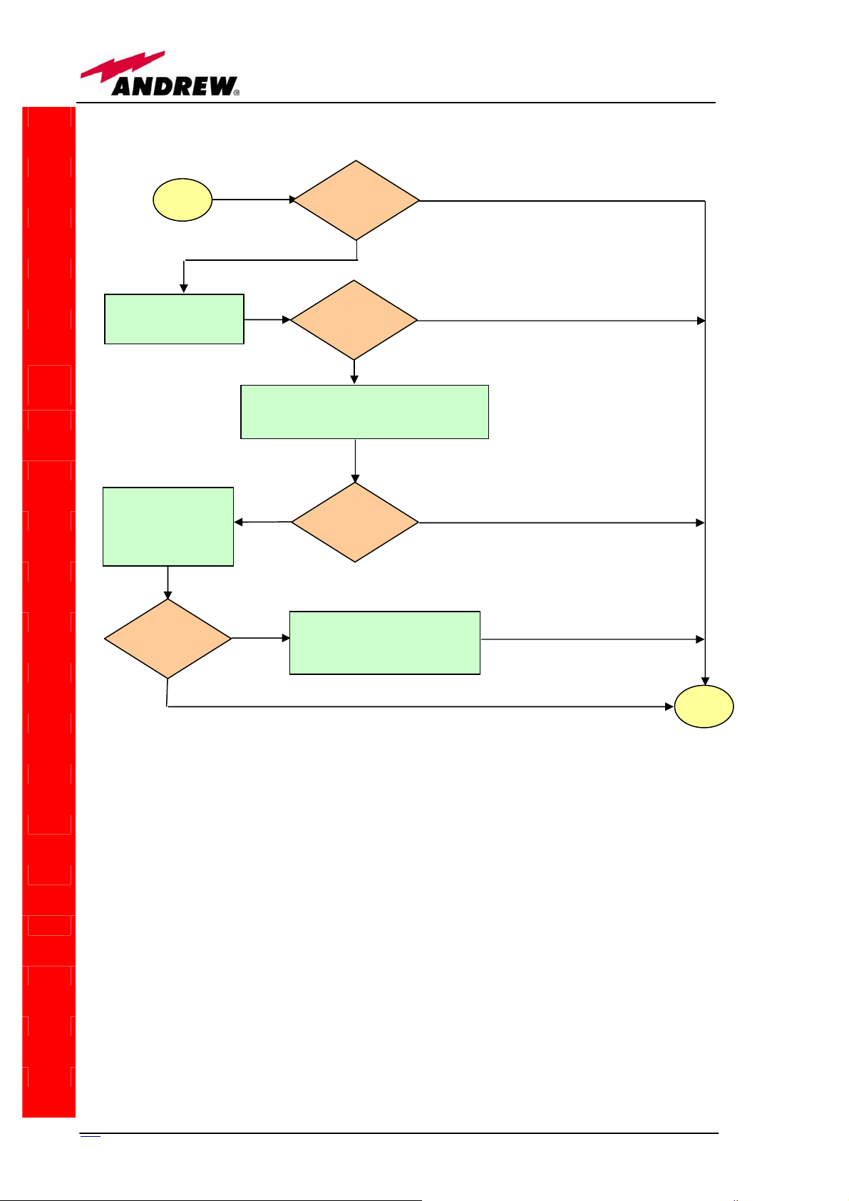
r
t
r
r
sta
Is the red LED
ON upon the
TSRX 2xx/8?
Yes
No
TILx-
-HL
Clean the SC-APC
optical adapter and
connecto
Reboot both the
TSRX-2xx/8 module
(on i-link slave side)
and the TMRX-200
(on i-link master-side)
Is red LED upon
TSRX 2xx/8
still ON?
No
Is red LED upon
TSRX 2xx/8
still ON?
Yes
Optical cable or optical connections may have
some problems. Refer to TMRX/TSRX
fiberoptic troubleshooting (fig. 5.34c)
Yes
Yes
Is red LED upon
TSRX 2xx/8
still ON?
Quick troubleshooting procedure
has not identified the
Refer to supervision
contact the manufacture
problem.
system or
No
No
end
Fig. 5.34(c): Flow-chart describing the quick TSRX2xx/8 troubleshooting.
194
User Manual
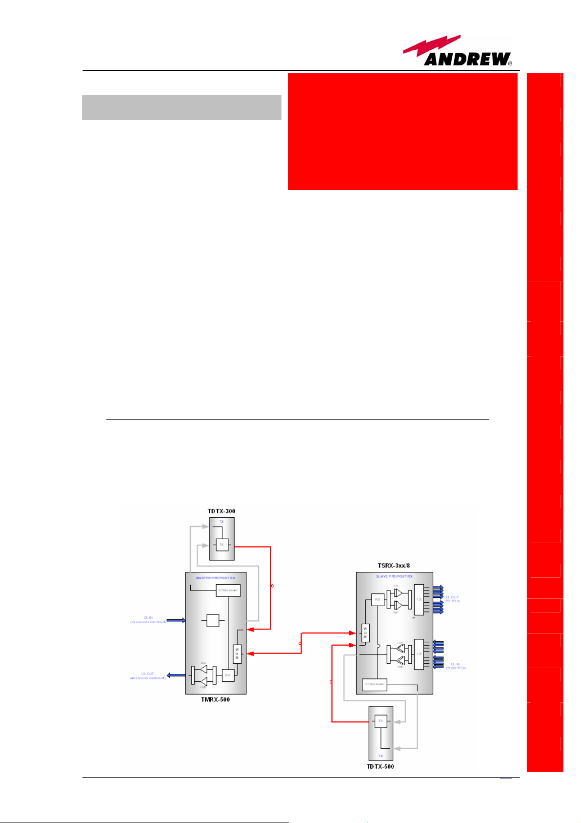
x
W
Module name:
5.11.3. TILx-HLW i-link
Module description:
The WDM interconnect link is a
composite module, made up by a
transmitter and a receiver module
both on master and on slave side:
• Master side
-TDTX-300 (transmitter module, hosted by 1 subrack slot)
-TMRX-500 (receiver module, hosted by 1 subrack slot)
• Slave side
-TDTX-500 (transmitter module, hosted by 1 subrack slot)
-TMRX-3xx/8 (receiver module, hosted by 3 subrack slots)
The TILx – HLW kit is available in EU tri-band version (EGSM 900MHz, GSM
1800MHz, UMTS), in US dual-band version (SMR 800MHz & Cellular 800MHz,
PCS 1900 MHz), and in hybrid version (SMR 800MHz & Cellular 800MHz, GSM
1800MHz, UMTS). These versions just differs in the slave-side receiver TSRX
module, which is the only module whose features vary with the RF
transmitting band.
Block scheme
A scheme of the system, is reported hereinafter, so as describe the
connections between the Interconnect-link modules and to give an insight of
the function of the modules named above.
Fig.5.35 – Scheme of the
WDM interconnect link
WDM interconnect
link
TIL
-HL
TILx-
-
HLW
MN024-08
195

6
Main TILx-HLW functions:
TILx-
-
HLW
Downlink:
Master side:
Slave side
Uplink:
Master side:
Slave side:
• RF-to-Optical conversion of the signal coming from the
splitting/combining section, and transmission to the slave
i-link modules via fiberoptics cable;
• Modulation and RF-to-Optical conversion of the bus
information, and transmission to the slave i-link modules
via fiberoptics cable (on 1310 nm wavelength);
• Optical-to-RF conversion of signal and alarm information,
with Automatic Gain Control (AGC) in order to
compensate the optical losses;
• Distribution of the RF signal to the TFLN optical TRXs, and
demodulation of the bus information
• Optical-to-RF conversion of signal and alarm information,
with Automatic Gain Control (AGC) in order to
compensate optical losses
• Distribution of the RF signal to the splitting/combining
section, and demodulation of the alarm information
• RF-to-Optical conversion of the signal coming from the
TFLN optical TRXs, and transmission to the master i-link
modules via fiberoptics cable;
• Modulation and RF-to-Optical conversion of the alarm
information, and transmission to the master i-link
modules via fiberoptics cable (on 1310 nm wavelength);
19
User Manual
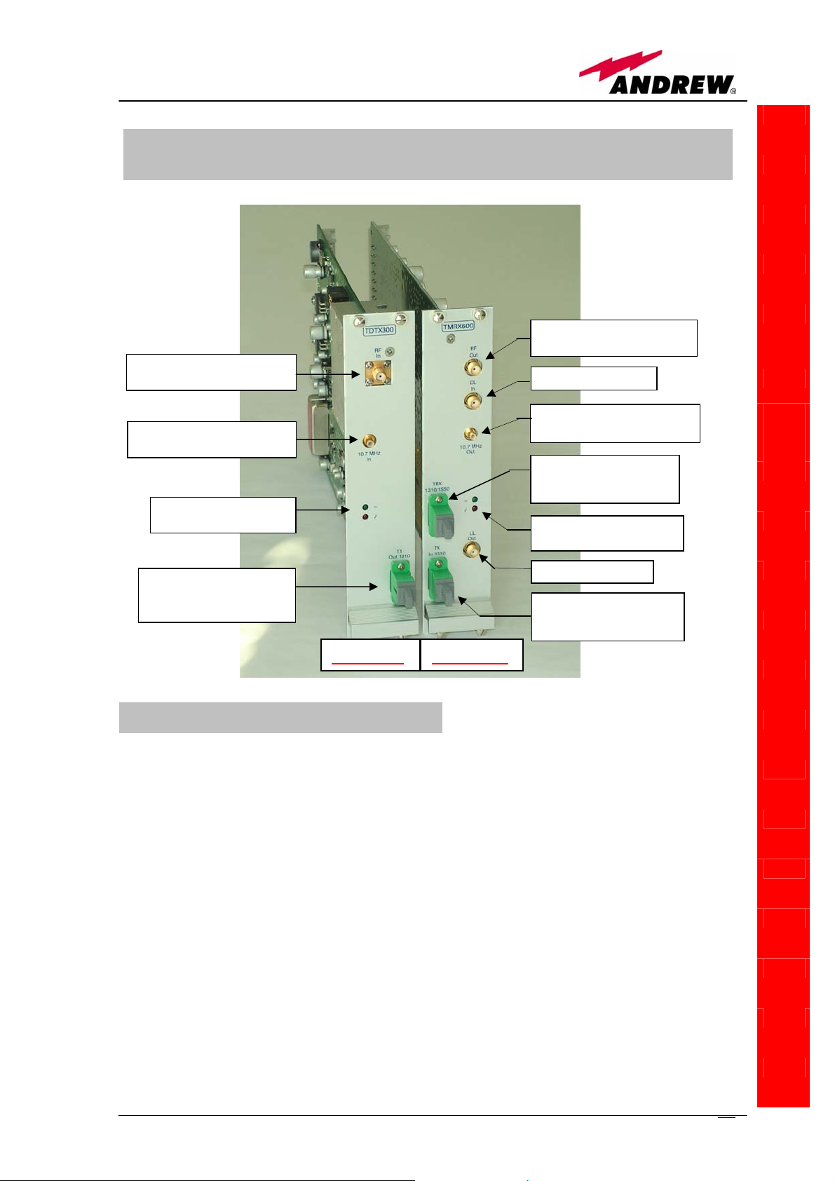
TILx-HLW Master Side:
)
r (
(
r
(
)
j
jor
TDTX300 transmitter + TMRX500 receiver
RF port connected to TMRX500
TILx-HLW Master-side: RF ports
TDTX300 transmitter
TMRX500 receiver
SMA-f)
maste
Alarm in port connected to
TMRX500 master
GREEN LED: power on
RED LED: ma
Optical port connected to
TMRX 500 master (SC-APC)
SMB-m)
or alarm
TDTX300 TMRX500
¾ 1 RF input port , to be connected directly to the RF
output port of the TMRX500 adjacent module
¾ 1 alarm input port, to be connected directly to the
alarm output port of the TMRX500 adjacent module
¾ 1 RF output port, to be connected directly to the RF
input port of the TDTX300 adjacent module
¾ 1 alarm output port, to be connected directly to the
alarm input port of the TDTX300 adjacent module
¾ 1 RF DL port, sent to the passive devices which
interface the Britecell with the BTS
¾ 1 RF UL port, coming from the passive devices which
interface the Britecell with the BTS
Fig. 5.36: WDM i-link
master side is made
up by a TDTX300
transmitter and by a
TMRX500 receiver
RF port connected to TDTX300
SMA-f)
maste
DL RF port (SMA-f
Alarm out port connected to
TDTX300 master (SMB-m)
Optical port connected to
slave TSRX3xx/8 (SCAPC
GREEN LED: power on
RED LED: ma
UL RF port (SMA-f)
Optical port connected to
TDTX300 master (SC-APC)
alarm
TILx-
-
HLW
MN024-08
197

T
TILx-
-
HLW
TILx-HLW Master-side: Optical ports
TDTX300 transmitter:
TMRX500 receiver:
TILx-HLW Master-side: LED Alarms
TDTX300 transmitter:
TMRX500 receiver
¾ 1 output port (1310 out), to be connected directly
to the optical input port of the master-side
TMRX500 receiver
¾ 1 input port (1310 in), to be connected directly to the
optical output port of the master-side TDTX300
transmitter
¾ 1 WDM TRX port (1310/1550), to be connected to the
TSRX3xx/8 module on the slave side
Two control LEDs (one green, one red) are placed on
the TDTX300 front panel. The green LED describes
the power supply status of the TDTX module, while
the red LED describes the major TDTX failure.
Two control LEDs (one green, one red) are placed on the
MRX500 front panel. The green LED describes the power
supply status of the TDTX module, while the red LED
describes the major TMRX failure.
Led
colour
Red
Green Power supply OK
Meaning
Optical power failure, wavelength out of
range, power supply failure
Table 5.20. Summary of TDTX300 LEDs meaning
Led
colour
Red
Green Power supply OK
Meaning
Power supply failure, modem failure, RF UL
failure, AGC compensation failure
Table 5.21 summary of TMRX500 LEDs meaning
198
User Manual
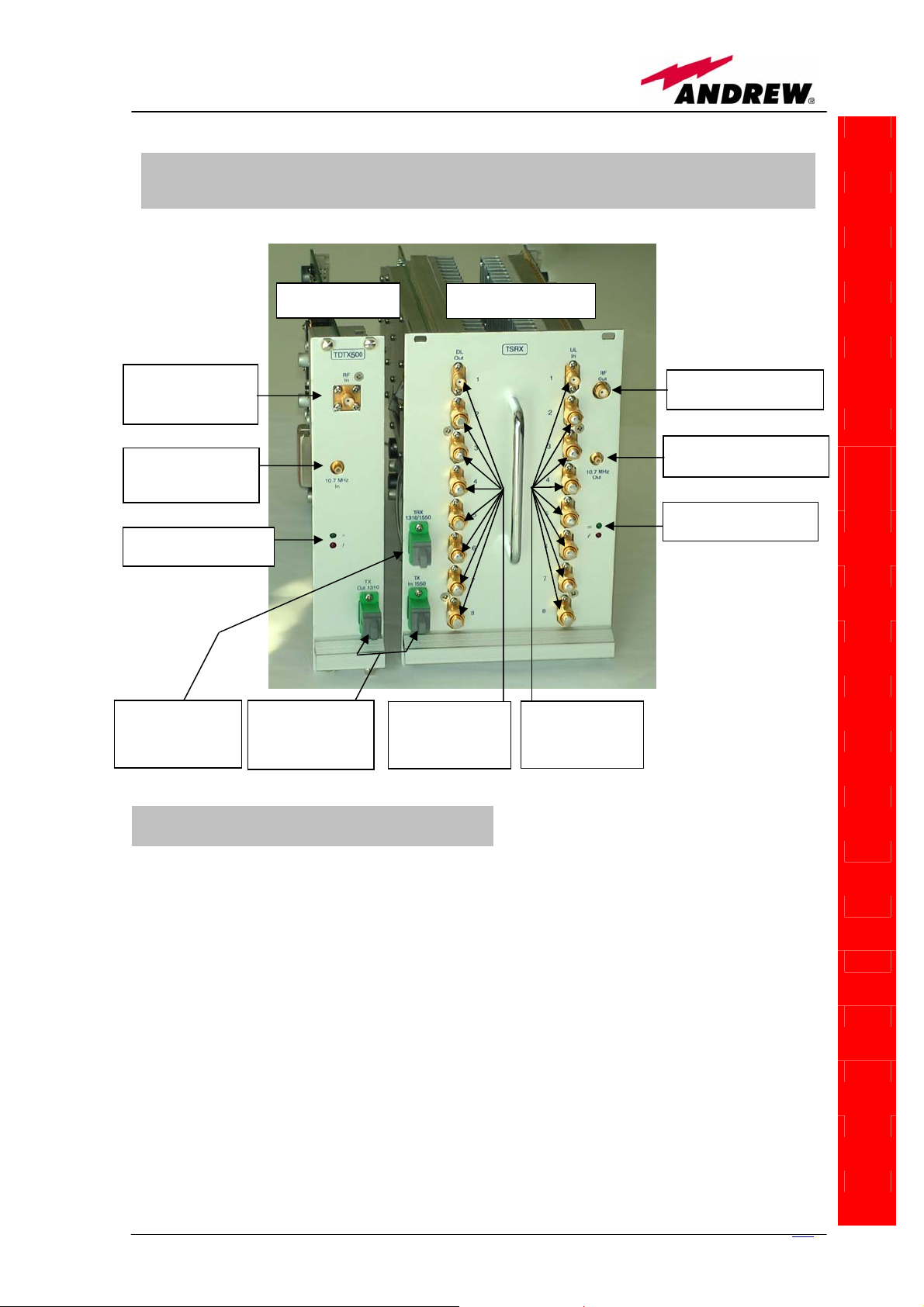
p
(
)
(
jumper
(
j
j
m
TILx-HLW Slave-Side:
TDTX500 transmitter + TSRX3xx/8 receiver
TDTX 500
TSRX 3xx/8
RF port connected to
TSRX3xx/8 slave
(SMA-f)
RF port connected to
TSRX3xx/8 slave
SMB-m)
GREEN LED: pwr on
RED LED:ma
or alarm
Optical port to be
connected to
TMRX-500 master
SC-APC)
Optical ports to
connect each other
by the fiber optic
DL ports connected
to TFLN DL ports
(SMA-f)
UL ports connected
to TFLN UL ports
(SMA-f)
WDM I-link Slave-side: RF ports
TDTX500 transmitter:
¾ 1 RF input port , to be connected directly to the RF
output port of the TSRX3xx/8 adjacent module
¾ 1 alarm input port, to be connected directly to the
alarm out
ut port of the TSRX3xx/8 adjacent
TSRX 3xx/8 receiver
¾ 1 RF output port, to be connected directly to the RF
input port of the TDTX300 adjacent module
¾ 1 alarm output port, to be connected directly to the
alarm input port of the TDTX300 adjacent module
¾ 8 RF DL ports, which can feed up to 8 TFLN local
transmitters ;
¾ 8 RF UL ports, which can receive the UL signals from
up to 8 TFLN local transmitters.
Fig.5.37: the WDM
i-link master side is
made up by a
TDTX500
transmitter and by a
TSRX3xx receiver
RF Rx port from
TDTX500 slave
SMA-f
RF Rx port from TDTX500
slave (SMB-m)
TILx-
-
HLW
GREEN LED: power on
RED LED:ma
or alar
MN024-08
199

TILx-
-
HLW
WDM I-link Slave-side: Optical ports
TDTX 500 transmitter:
¾ 1 output port (1550 out), to be connected directly to
the optical input port of the slave-side TSRX 3xx/8
TSRX 3xx/8 receiver:
¾ 1 input port(1550 in), to be connected directly to
the optical output port of the slave-side TDTX500
transmitter
¾ 1 WDM TRX port (1310/1550nm), to be connected
to the TMRX500 module on the master side
WDM I-link Slave-side: LED Alarms
TDTX500 transmitter:
TSRX 3xx/8 receiver
Two control LEDs (one green, one red) are placed on the
TDTX300 front panel. The green LED describes the power
supply status of the TDTX module, while the red LED
describes the major TDTX failure.
Two control LEDs (one green, one red) are placed on
the TSRX3xx/8 front panel. The green LED describes
the power supply status of the TDTX module, while the
red LED describes the major TSRX failure.
Led
colour
Red
Green Power supply OK
Meaning
Optical power failure, wavelength out of
range, power supply failure
Led
colour
Red
Green Power supply OK
Meaning
Power supply failure, modem failure, RF UL
and DL failure, AGC compensation failure
Table 5.22:
Summary of
TDTX500 LEDs
meaning
Table 5.23:
Summary of
TSRX3xx/8 LEDs
meaning
Warnings (to be read before the TILx-HLW
installation)
Dealing with optical output ports
• The TDTX modules (both on master and on slave side) contain
semiconductor lasers. Invisible laser beams may be emitted from the
200
User Manual

optical output ports. Do not look towards the optical ports while equipment
is switched on.
•
Handling optical connections
• When inserting an optical connector, take care to handle it so smoothly
that the optical fibre is not damaged. Optical fibres have to be single-mode
(SM) 9.5/125µm.
• Typically, Britecell Plus equipment is provided with SC-APC optical
connectors. Inserting any other connector will result in severe damages.
• Do not force or stretch the fibre pigtail with radius of curvature less than 5
cm.
• Remove adapter caps only just before making connections. Do not leave
SC-APC adapters open, as they attract dust. Unused SC-APC adapters must
always be covered with their caps.
• Do not touch the adapter tip. Clean it with a proper tissue before inserting
each connector into the sleeve. In case adapter tips need to be better
cleaned, use pure ethyl alcohol
Inserting or removing TDTX, TMRX, TSRX modules
• Do not remove or insert any module into TPRN sub-rack before having
switched off main power supply.
• Modules must be handled with care, in order to avoid damage to
electrostatic sensitive devices.
• When installing the modules in the sub-rack, take care to alternate active
and passive cards in order to ensure proper heat dissipation.
• In a multi-sub-rack system, remember to assign to each sub-rack a proper
RS485 bus address before installing the modules (please refer to TPRN
section for further details).
Positioning the TILx-HLW modules inside the subrack
• The i-link modules at slave side should be installed in the middle of the
slave subrack, or at least they should have no more than 4 TFLN modules
both on the right side and on the left side of the TSRX
requirement is advised in order to allow connection between the TSRX
module and all the TFLN transmitters (see fig. 5.39)
3xx/8 module. This
TILx-HLW installation
The TILx-HLW modules are provided with:
Master Cable Installation Kit:
• 1 SMA-Male/SMA-Male RF
jumpers
• 1 SMB-Female/SMB-Female RF
jumper
• 1 Fiber Optic Jumper
Both on master side and on slave side, the WDM i-link modules are to be
housed into a TPRN active sub-rack.
Slave Cable Installation Kit:
• 17 SMA-Male/SMA-Male RF
jumpers
• 1 SMB-Female/SMB-Female RF
jumper
• 1 Fiber Optic Jumper
TILx-
-
HLW
MN024-08
201

(
S
)
TILx-
-
HLW
On the master-side station, the WDM i-link modules are to be housed into 2
adjiacent slots, chosen among the 12 available ones in the subrack.
On the slave-side subrack, the WDM i-link modules are to be housed into 4
adjiacent slots: moreover, due to the particular cabling they require, these 4
adjiacent slots should be placed in mid-subrack, so that no more than 4 TFLN
local units stay on each side of the WDM i-link modules (see fig. 5.39).
: If the TILx-HLW modules are to be installed in an already working
Note
Master Unit, switch off the sub-racks before inserting the modules.
Before inserting the boards into the TPRNx4 subracks, make sure to set
proper RS485 addresses. A basic rule of the Britecell installation is that 2
subracks belonging to the same Master Unit should always have different
RS485 addresses (please refer to “TPRN Installation” section): since the
interconnect-link basically provides an extension of the Master Unit bus, any
subrack on the i-link master-side should also have a RS485 address different
from any subrack on the i-link slave side.
Please refer to “TPRNx4 Installation” section for more information on setting
the RS485 address.
Firstly, carefully insert the TMRX-500 and the TDTX-300 boards in 2 adjacent
slots of the Master side subrack. Lock the 4 screws on the corners of each
boards.
Use the provided SMA-m RF jumper in order to connect the RF Out Port of the
TMRX500 module to the RF In Port of the adjacent TDTX300 module. Use the
SMB-f jumper to connect the 10.7MHz ports of the two boards. Fix these RF
jumpers to the RF ports through a proper torque wrench (not included).
Remove the protection cap from the optical ports of the 2 modules on the
master side.
Take the optical jumper, clean the fibre connectors, and use it to connect the
1310 output port of the TDTX 300 and the 1310 input port of the TMRX500
RF jumper
MA-m / SMA-m
RF jumper
(SMB-f / SMB-f)
Fig. 5.38: TILx-HLW master side
optical jumper
UL/DL optical cable
202
User Manual

module.
Take a SC-APC fiber, clean the fibre termination, and connect it to the
1310/1550 TRX port of the TMRX 500 module (This fiber shall be directly
connected to the 1310/1550 TRX port of the TSRX 3xx/8 on the slave-side
subrack)
Carefully insert the TSRX-3xx/8 and the TDTX-500 boards in 4 adjacent slots
of the Master side subrack. As already explained, take care not to have more
than 4 TFLN modules on each side of the i-link pieces. Lock the 4 screws on
the corners of each boards.
Use the provided SMA-m RF jumper in order to connect the RF Out Port of the
TSRX 3xx/8 module to the RF In Port of the adjacent TDTX500 module. Use
the SMB-f jumper to connect the 10.7MHz ports of the two boards.
Use the longer RF jumpers (included) to connect each pair of TSRX UL and DL
ports to the corresponding UL and DL ports of each TFLN module mounted on
slave-side subrack. If less than 8 TFLNs are used at slave-side, make sure to
mask the TSRX-3xx/8 unused DL and UL ports by SMA loads (not provided).
Remove the protection cap from the optical ports of the 2 modules on the
slave side.
Take the optical jumper, clean the fibre connectors, and use it to connect the
1550 output port of the TDTX500 and the 1550 input port of the TSRX3xx/8
module.
Connect the 1310/1550 TRX port of the TSRX3xx/8 module to the fiberoptics
cable coming from the 1310/1550 TRX port of the TMRX500 module on the
master-side.
TILx-
-
HLW
UL/DL optical cable
Fig. 5.39: TILx-HLW slave side
Optical
jumper
As you switch on the system, carefully refer to the “TILx-HLW start-up”
section.
MN024-08
203

TILx-
-
HLW
Removing a TILx-HLW module
To remove a TILx-HLW module, firstly switch off the TPRNx4 subrack which
houses the module.
Remove the fibers and the RF jumpers connected to the WDM i-link module
which is going to be removed. Insert the caps on the optical ports which has
just been disconnected.
Unscrew the 4 screws at the corners of the WDM i-link module which is going
to removed, and slowly remove the card.
Put the card in its safety box
TILx-WDM start-up
Before both the master side station and the slave-side stations are switched
on, make sure that:
• all expected modules have been inserted into the Master Unit
• the modules have been connected each other by RF jumpers, according to
what planned in the system design
• the TILx-HLW master modules have been connected to the relevant TILx-
HLW slave modules through fiberoptics cables;
• every TFLN master optical TRX has been connected to relevant remote
units
• each remote unit has been connected to its coverage antennas
• the remote supervision unit, if present, has been connected to the Master
Unit
• both on the master-side and on slave-side stations, different subracks are
connected each other via bus RS485
After that, remember that only when all the remote units are already on, the
different subracks composing the Master Unit can be switched on. Once all
the active subracks have been switched on, the behaviour of the different ilink modules can be summarized as follows:
o All the LEDs on the different TILx-HLW modules (both on master side
and on slave side) turn on for a couple of seconds;
o After that, all the green LEDs on the different modules remain ON (thus
indicating proper power supply), while the red LEDs switch off as soon as
the master-side and the slave-side detect each other;
o During normal working operations, the status of the LED should be the
one described in table 3.
o Once all the master-side and slave-side subracks have been switched
on, the system should begin to work correctly. Anyway, in order that the
i-link modules are recognized by the supervision management system, it
is necessary that the system carries out the discovery phase (please
refer to Supervision System Manual for more details). During this phase,
whose duration depends on the system complexity and which can last at
max. 4min, the TFLN LEDs ┌┘ blink. Do not connect/disconnect any
204
User Manual

cable or any piece of equipment during the discovery phase! This
may result in failing the identification of some equipment.
: in case discovery doesn’t start automatically, check through the LMT or
Note
the remote supervision whether it has been disabled (refer to LMT or remote
supervision system manuals for further information).
o Finally, please note that the receiver module TSRX3xx/8 has only one
connection with the subrack backplane, so that the LMT software and the
supervision system will detect it as a 1-slot card. More in details, only the
slot which hosts the TSRX LED alarms is recognized by LMT or
supervision. The other 2 slots hosting the TSRX receiver are therefore to
be masked through the LMT or the Supervision System Interface (please
refer to the relevant user manuals) in order to avoid fictitious alarm
notifications.
TILx-HLW troubleshooting
Faults on the i-link modules can be revealed:
• by LEDs on the front panels of the modules themselves
• by the LMT software running on a PC connected to a master side or a slave-
side subrack via RS232 port;
• by the supervision system interface managed by the remote supervision
unit, usually placed conveniently on the master-side.
Both LMT and supervision system provide full information about the device
causing the alarm. As a consequence, troubleshooting procedure can be very
immediate when failure detection is directly carried out through LMT or
supervision system.
The tables 5.24, 5.25, 5.26, 5.27 report a brief description of alarm related to
the different i-link modules, together with a reference to corresponding alerted
LEDs and to possible recovery actions.
TILx-
-
HLW
MN024-08
205

6
TILx-
-
HLW
ALARM
CODE
(TSUN
description)
Vcc alarm
Optical
Power
< 1dB
Optical power
< 3 dB
ALARM
DESCRIPTION
There is a degradation
on the power supply
provided by the
backplane
The received optical
power experiences a
degradation which is
near to the AGC
working threshold (but it
can still compensate
losses)
The transmitted optical
power experiences a
degradation which can
no more be compensated
by the AGC.
TDTX300 (master side)
ACTIVE
LED
RED MAJOR Return the unit MAJOR
NONE MINOR
RED MAJOR Return the unit MAJOR
SUPERVISION
PRIORITY
LEVEL
ACTION
RECOMMENDED
Check the optical loss /
AGC status on the
TSRX or TMRX
module at the other side
of the imterconnect link
RELÉ
PRIORITY
LEVEL
(subrack)
MINOR
Temperature
Alarm
Over-temperature alarm NONE WARNING
Table 5.24: Description of the TDTX300 alarms, as they are described by the LMT
software or by the supervisione interface
Check the subrack and
cabinet ventilation,
verify the
environmental
conditions involving
heating and air
circulation
MINOR
20
User Manual

ALARM
CODE
(TSUN
description)
Power supply
alarm
AGC out of
range
Optical power
fail
Temperature
alarm
FSK modem
alarm
ALARM
DESCRIPTION
There is a degradation
in power supply
distribution
The received optical
power experiences a
degradation which is
near to the AGC
working threshold (but
it can still compensate
losses)
The transmitted optical
power experiences a
degradation which can
no more be
compensated by the
AGC
Over-temperature alarm NONE WARNING
HW problem on the
10.7 MHz FSK
modulator/ demodulator
UL RF alarm UL Hardware failure RED MAJOR Return the unit MAJOR
Current Fail Overcurrent alarm RED MAJOR Return the unit MAJOR
Table 5.25: Description of the TMRX500 alarms, as they are described by the LMT software or by
the supervisione interface
TMRX500 (master side)
ACTIVE LED
RED MAJOR Return the unit MAJOR
NONE WARNING
RED MAJOR Return the unit MAJOR
RED CRITICAL Return the unit MAJOR
SUPERVISION
PRIORITY
LEVEL
ACTION
RECOMMENDED
Check the optical loss /
AGC status on the
TSRX or TMRX
module at the other
side of the
imterconnect link
Check the subrack and
cabinet ventilation,
verify the
environmental
conditions involving
heating and air
circulation
RELÉ
PRIORITY
LEVEL
(subrack)
MINOR
MINOR
TILx-
-
HLW
MN024-08
207

TILx-
-
HLW
TDTX500 (slave side)
ALARM
CODE
(TSUN
description)
Vcc alarm
Optical power
< 1 dB
Optical power
< 3 dB
Temperature
Alarm
ALARM
DESCRIPTION
There is a degradation on
the power supply
provided by the
backplane
The received optical
power experiences a
degradation which is near
to the AGC working
threshold (but it can still
compensate losses)
The transmitted optical
power experiences a
degradation which can no
more be compensated by
the AGC.
Over-temperature alarm NONE WARNING
Table 5.26: Description of the TDTX500 alarms, as they are described by the LMT
software or by the supervisione interface
ACTIVE
LED
RED MAJOR Return the unit MAJOR
NONE MINOR
RED MAJOR Return the unit MAJOR
SUPERVISION
PRIORITY
LEVEL
ACTION
RECOMMENDED
Check the optical loss
/ AGC status on the
TSRX or TMRX
module at the other
side of the
imterconnect link
Check the subrack and
cabinet ventilation,
verify the
environmental
conditions involving
heating and air
circulation
RELÉ
PRIORITY
LEVEL
(subrack)
MINOR
MINOR
208
User Manual

ALARM
CODE
(TSUN
description)
Power supply
alarm
AGC out of
range
Optical power
fail
Temperature
alarm
FSK modem
alarm
TSRX3xx/8 (slave side)
ALARM
DESCRIPTION
There is a degradation in
power supply distribution
The received optical
power experiences a
degradation which is
near to the AGC working
threshold (but it can still
compensate losses)
The transmitted optical
power experiences a
degradation which can
no more be compensated
by the AGC
Over-temperature alarm NONE WARNING
HW problem on the 10.7
MHz FSK
modulator/demodulator
ACTIVE LED
RED MAJOR Return the unit MAJOR
NONE WARNING
RED MAJOR Return the unit MAJOR
RED CRITICAL Return the unit MAJOR
SUPERVISION
PRIORITY
LEVEL
RELÉ
ACTION
RECOMMENDED
PRIORITY
LEVEL
(subrack)
Check the optical loss
/ AGC status on the
TSRX or TMRX
module at the other
side of the
interconnect link
Check the subrack and
cabinet ventilation,
verify the
environmental
conditions involving
heating and air
circulation
MINOR
MINOR
TILx-
-
HLW
DL Low band
RF alarm
DL High
band RF
alarm
DL UMTS
RF alarm
(only on
TSRX 347/8
version)
UL Low band
RF alarm
UL High
band RF
alarm
UL UMTS
RF alarm
(only on
TSRX 347/8
version)
Current Fail Overcurrent alarm RED MAJOR Return the unit MAJOR
HW failure on the DL
RF low band
HW failure on the DL
RF high band
HW failure on the DL
RF UMTS band
HW failure on the UL
RF low band
HW failure on the UL
RF high band
HW failure on the UL
RF UMTS band
RED MAJOR Return the unit MAJOR
RED MAJOR Return the unit MAJOR
RED MAJOR Return the unit MAJOR
RED MAJOR Return the unit MAJOR
RED MAJOR Return the unit MAJOR
RED MAJOR Return the unit MAJOR
Table 5.27: Description of the TSRX3xx/8 alarms, as they are described by the LMT
software or by the supervisione interface
MN024-08
209

TILx-
-
HLW
As shown by these tables, the LEDs show only the alarms concerning the
board where they are housed: so, a red LED which is switched on at TSRX
front side reveals an alarm affecting the TSRX module itself (it does not deals
with the alarms affecting the other module of the i-link slave-side, which is an
TDTX300, and whose alarms will be detected by its own LEDs). Moreover,
these tables show that the LEDs reveals only major alarms, whereas the
minor alarms (i.e. the low priority ones) are revealed only by the LMT
software or through the TSUN supervision system. The minor alarms usually
detect critical situations which should be checked so as to avoid future
possibile system faults.
Although any alarm detected by a LED on the i-link modules should be
verified through LMT or supervision software when an accurate check is
needed, some ordinary maintenance procedures could be carried out quickly
following the instructions described hereinafter.
TDTX300 and TDTX500 troubleshooting
The TDTX modules are basically two optical transmitters whose alarm status
cannot be influenced by dirt optical adapters or by some problems in
fiberoptics cables. If any red light is switched on in a TDTX front panel, please
check if you have connected properly the RF jumpers. If the RF connections
prove to be ok and the red LED keeps on switching on, please contact the
manufacturer.
TMRX500 module troubleshooting
Ordinary troubleshooting procedures which can be carried out on TMRX500
module first involve a check of the optical adapters status and of the
fiberoptics cables. If the alarm status still persists, a reboot of both the
TMRX500 module and of the TSRX3xx/8 module can be performed so as to
re-inizialize the link.
Quick TMRX-500 troubleshooting procedure
(The following procedure is summarized by the flow-chart in fig. 5.40b)
In case the red LED is ON, please follow these steps:
1. Clean the optical adapter
2. If the problem still persists, refer to TMRX/TSRX fiber optical
troubleshooting so as to check if the optical connectors and, the optical
cable and the optical jumpers have some problems.
3. If previous actions didn’t make the LED switch off, a reboot of both the
TMRX500 module and of the TSRX3xx/8 module (on the slave-side) could
be performed so as to test modem connectivity.
4. If the red LED still remains on, please check the alarm status by the LMT or
the supervision unit in order to better understand the problem and its
possible solution.
210
User Manual

TMRX/TSRX fibre optic troubleshooting
(The following procedure is summarized by the flow-chart in fig. 5.40b)
1. Check if there is any point where fibre experiences a short radius of
curvature. In this case, rearrange the optical path in order to avoid sharp
bends (if necessary, replace the optical cable with a longer one). If TMRX
(TSRX) red LED switches off, troubleshooting has been successfully
carried out. Otherwise, follow next steps.
2. Check if SC-APC connectors are properly installed at both fibre ends. In
case they are not, fix more firmly the SC-SPC connectors to their
adapters. If the TMRX (TSRX) red LED switches off, troubleshooting has
been successful. Otherwise, follow next steps.
3. Disconnect the optical fibre and clean it better at both ends, then clean
also the relevant SC-APC adapters. Re-connect the fibre to relevant ports
after cleaning. If it doesn’t make TMRX (TSRX) red LED switch off, follow
next steps.
4. Disconnect the fiber from the TMRX (TSRX) port, and measure the power
Pout which comes out from the fiber. Then, go to the module where the
other end of the fiber is connected (it can be either on the slave side and
on the master side, depending on the fiber or on the jumper you are
verifying), disconnect it and measure the input power Pin coming out of
the port. Calculate the fibre attenuation A due to the fiberoptics cable: Af
[dB] = Pin – Pout
a. If Af > 10 dB, then the fibre optic cable has some problems. Replace it
with a new one.
b. If Af < 10 dB troubleshooting procedure has not identified the
problem. Refer to supervision system or contact the manufacturer for
assistance.
TSRX3xx/8 module troubleshooting
Ordinary troubleshooting procedures which can be carried out on TMRX200
module first involve a check of the optical adapters status and of the
fiberoptics cables. If the alarm status still persists, a reboot of both the TMRX500 module and of the TSRX3xx/8 module can be performed so as to reinizialize the link.
Quick TSRX3xx/8 troubleshooting procedure
In case the red LED is ON, please follow these steps:
1. Clean the optical adapter
2. If the problem still persists, refer to the fibre optic troubleshooting so as to
check if the optical cable or optical connection has any problem.
3. If previous actions didn’t make the LED switch off, a reboot of both the
TSRX3xx/8 module and of the TMRX500 module (on the master side) could
be performed so as to test modem connectivity.
4. If the red LED still remains on, please check the alarm status by the LMT or
the supervision unit in order to better understand the problem and its
possible solution.
TILx-
-
HLW
MN024-08
211

r
t
r
r
TILx-
-
HLW
sta
Clean the SC-APC
optical adapter and
connecto
Optical cable, optical jumper or optical connections
may have some problems. Refer to TMRX/TSRX
fiberoptic troubleshooting (fig. 5.40b)
Reboot both the
TMRX 500 module
(on i-link master side)
and the TSRX-347/8
(on i-link slave-side)
Yes
Is red LED upon
TMRX 500 still
ON?
Yes
No
Fig. 5.40a: Flow-chart describing the quick TMRX500 troubleshooting.
Is the red LED
ON upon the
TMRX 500?
Yes
Is red LED upon
TMRX 500 still
ON?
Yes
No
Is red LED upon
TMRX 500 still
ON?
Quick troubleshooting procedure
has not identified the
Refer to supervision
contact the manufacture
No
problem.
system or
No
end
212
User Manual
 Loading...