


REP1009V1.xx
REP1009V1.xx ( Id.-No. 147127 )
Software manual
for band/channel selective Repeater
Copyright MIKOM, Buchdorf 1998
All rights reserved.
No parts of this publication may be
reproduced, stored in a retrieval system, transmitted in any form or by
any means, electronical, mechanical photocopying,
recording or otherwise, without prior written permission of the
publisher.
Author: Approved: QA:
M0062A0B.doc Id.-No. 148964 Page 1 6-Apr-99

REP1009V1.xx
Table of contents
LIST OF UNIT SPECIFIC ABBREVIATIONS 4
1 INTRODUCTION 5
2 INSTALLATION 6
3 SOFTWARE DOWNLOAD 7
3.1 Download procedure in local mode 7
3.1.1 Download procedure in local mode, software controlled: 7
3.1.2 Download procedure in local mode, manually controlled: 8
4 RUNNING THE SOFTWARE 10
4.1 Via PC or Laptop as terminal 10
4.2 Via modem 12
4.2.1 PSTN modem 12
4.2.2 Siemens M1 modem for GSM900 14
4.2.3 Motorola mobile ( CELLect1 card ) 14
5 DESCRIPTION OF THE COMMANDS 15
5.1 Instruction modes 15
5.2 Conventions 15
5.3 Description of SET commands 16
5.3.1 SET ALARMMASK, definition of the severity level for an alarm 17
5.3.2 SET ALCTHR, setting of the ALC threshold 18
5.3.3 SET ALIAS*, enter name strings for external alarms 1 ... 4 19
5.3.4 SET ATT, sets attenuation in uplink or downlink path 19
5.3.5 SET BAUD, definition of baudrate used 19
5.3.6 SET CF, setting of the center frequency 20
5.3.7 SET CFO, setting of the frequency offset 20
5.3.8 SET DIALMETH, setting of the dialing method 20
5.3.9 SET ID, Repeater identification 20
5.3.10 SET ILA, definition of a limit for invalid login attempts 21
5.3.11 SET INITSTR, definition of a initialisation string 21
5.3.12 SET LMT, to change timeout for local maintenance interface 21
5.3.13 SET LOGIC, definition of the I/O port logic for the external alarms 22
5.3.14 SET NUM, definition of 2 phone numbers used for the automatic dial out 22
5.3.15 SET PAR, definition of parity 22
5.3.16 SET PWD, to change password 22
5.3.17 SET PWRDOWN, to switch off band modules 23
5.3.18 SET REP, definition of waiting time between alarm call trials 23
5.3.19 SET TIME, to change actual time and date 24
5.3.20 SET UID, changes user identification 24
M0062A0B.doc Id.-No. 148964 Page 2 11.12.98

REP1009V1.xx
5.4 Description of the GET commands 25
5.4.1 GET ALARMMASK, displays the set severity level for an alarm 27
5.4.2 GET ALCTHR, displays the set value for the ALC threshold 27
5.4.3 GET ALIAS*, name strings for external alarms 27
5.4.4 GET ATT, gain setting 28
5.4.5 GET BAUD, baudrate 28
5.4.6 GET CF, set centre frequency in the GSM900 / GSM1800 band 28
5.4.7 GET CFO, frequency offset 29
5.4.8 GET ID, Repeater identification 29
5.4.9 GET ILA, displays stored number of invalid login attempts 29
5.4.10 GET INITSTR, displays the string which is used to initialize the modem 29
5.4.11 GET LMT, timeout for local interface 30
5.4.12 GET LOGIC, displays the logic of the I/O ports 30
5.4.13 GET NUM, displays stored phone numbers 30
5.4.14 GET PAR, modem parity 30
5.4.15 GET PWRDOWN, displays power down status of the modules 30
5.4.16 GET REP, defines waiting time between trials for automatic alarm call 31
5.4.17 GET TIME, to get the actual time and date 31
5.5 Status commands 32
5.5.1 STATUS ALC, displays the actual status 33
5.5.2 STATUS AMPBIAS, current consumption of the RF modules 33
5.5.3 STATUS DOOR, door open / closed 33
5.5.4 STATUS HIST, list of all occurred alarms 33
5.5.5 STATUS I2C , displays the status of the I²C bus 35
5.5.6 STATUS LBATT, response information about Lithium battery 35
5.5.7 STATUS PWR, status of the power supplies 35
5.5.8 STATUS SYNTH, modules in operation 35
5.5.9 STATUS TEMP, temperature 36
5.6 Optional status commands 37
5.6.1 STATUS ACCU, response voltage value of backup battery 37
5.6.2 STATUS EXTALARM, status of external alarms 37
5.6.3 STATUS VSWR, displays the DL antenna VSWR 37
5.7 Action commands 38
5.7.1 ALARMACKN, acknowledgement of all alarms. 38
5.7.2 BYE, disconnect Repeater from telephone line in remote mode 38
5.7.3 BYE, disconnect Repeater from local maintenance interface 39
5.7.4 DNLOAD, starts software download 39
5.7.5 VER, displays the version of software and hardware 39
5.8 Optional action commands 40
5.8.1 ACCUDIS, starts discharge of accumulator 40
5.8.2 STOPDIS, stops battery discharging immediately 40
5.9 Error messages 41
5.9.1 SYNTAX ERROR 41
5.9.2 VALUE ERROR 41
5.9.3 I²C-BUS ERROR 41
5.10 Features 41
6 INDEX 42
M0062A0B.doc Id.-No. 148964 Page 3 11.12.98

REP1009V1.xx
LIST OF UNIT SPECIFIC ABBREVIATIONS
ALC Automatic Level Control
DL Downlink
EEPROM Electrical erasable programming read only memory
I²C-Bus Inter Integrated Circuit Bus
LMT Local Maintenance Terminal
MR Mikom Repeater
OMC Operation and Maintenance Center
RF Radio Frequency
RSSI Receive Signal Strength Indication
UL Uplink
UPS Uninterruptable Power Supply
VSWR Voltage Standing Wave Ratio
M0062A0B.doc Id.-No. 148964 Page 4 11.12.98
REP1009V1.xx
1 Introduction
This manual describes the functions of the standard software REP1009V1.xx implemented in
band/channel selective Repeaters of the second generation. These Repeaters can be set locally
or remotely. A PCMCIA slot for modem operation is available. The design of the Repeater
comprises a large number of functions which the operator may monitor via terminal emulation
program or the MIKOM OMC software platform. An easy to understand and easy to learn
communication language supports the operator to query status reports from the Repeater or to
change settings.
Your Repeater is equipped with the required software which enables the operator to
communicate with the microprocessor of the control module.
The communication with the microprocessor of the control module is realized with a VT100
compatible dialogue.
The software is accessible in two different ways.
n Locally
n Remotely
Both possibilities are described below.
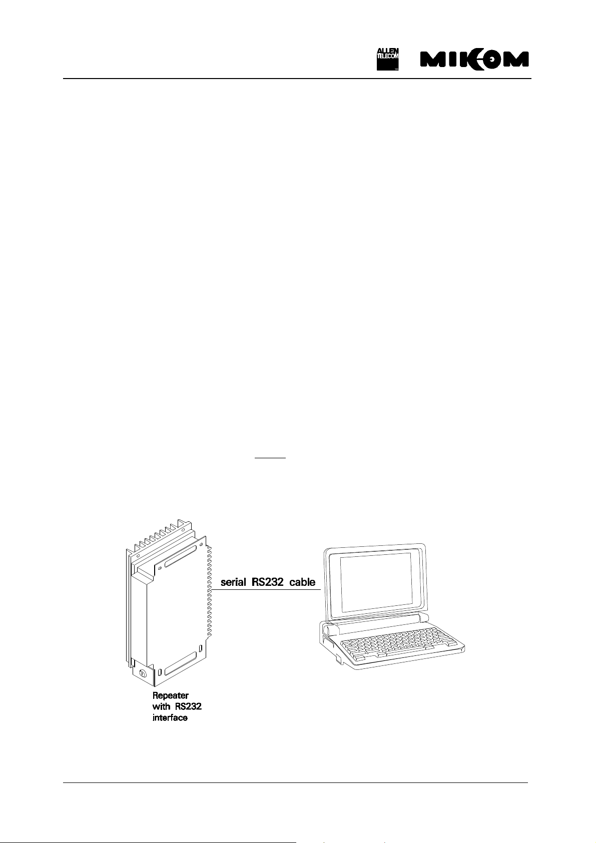
• The communication can be done locally by connecting a Laptop or a PC with VT100
emulation or a VT100 terminal via the control cable.
Required equipment: - Laptop or PC with terminal program, e.g. PROCOMM
- one serial RS232 cable: SUB-D9 (female) to SUB-D9 (female)
Laptop or PC
with terminal program
figure 1-1 Repeater locally controlled
M0062A0B.doc Id.-No. 148964 Page 5 11.12.98
REP1009V1.xx
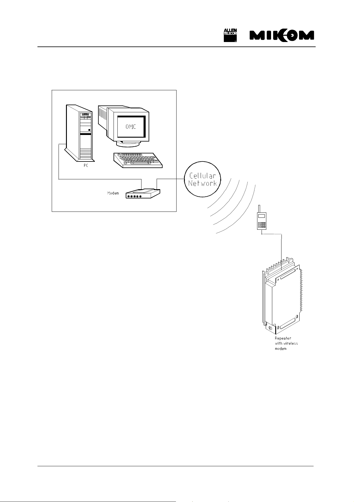
• Furthermore the communication can be realized remotely via modem.
figure 1-2 Repeater remotely controlled
2 Installation
The actual software version is part of the delivery schedule of your Repeater unit and will be
installed in factory.
M0062A0B.doc Id.-No. 148964 Page 6 11.12.98
REP1009V1.xx
OFF
ON
3 Software download
It might be necessary to download another software version. This can be realized in two
different ways.
n Software download in local mode
n Software download in remote mode
3.1 Download procedure in local mode
Two different download procedures exist in local mode. The software download software or
manually controlled. After a software download previous user settings ( data default values )
might be overwritten. Before you start a software download save the set values for:
n attenuation
n ALC threshold
3.1.1 Download procedure in local mode, software controlled:
Required equipment: - PC with terminal program, e.g. PROCOMM
- one serial RS232 cable: SUB-D9 (female) to SUB-D9 (female)
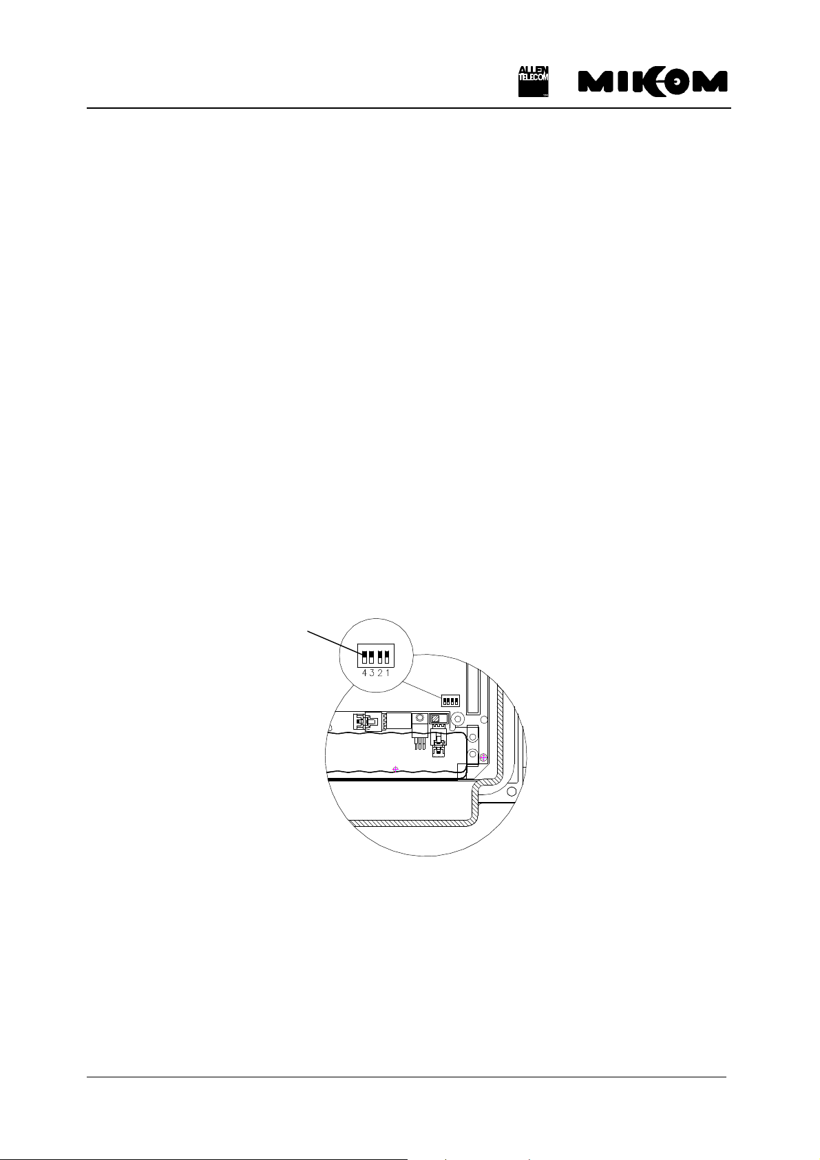
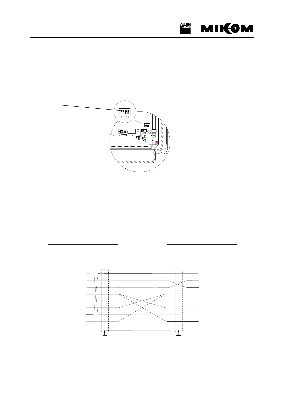
1. Check the position of DIP-Switch 4 ( position OFF ) on the control module.
DIP-Switch 4
figure 3-1 Position of DIP-Switch 4
1. Switch on Repeater and PC and connect control cable. Wait until the boot process is
finished.
2. Start Repeater software and login by typing ‘User-ID1’ and ‘P-word1’.
3. Type software command:
Syntax: DNLOAD ↵
4. Exit terminal program immediately.
M0062A0B.doc Id.-No. 148964 Page 7 11.12.98
REP1009V1.xx
OFF
ON
5. To start upload procedure type:
Syntax: upload 1 ↵ or
upload 2 ↵
depending on which serial interface is available ( COM 1 or COM 2 ).
6. The copy procedure is running. You will be asked to continue by pressing any key. Now the
software download is in progress. The download lasts approximately 1 minute.
7. Software boot starts automatically.
Response: ‘MIKOM REPEATER MRx01A - SM2009 - SW:REP1009V1.xx’
ENTER <.> <CR> TO LOGIN
3.1.2 Download procedure in local mode, manually controlled:
Required equipment: - PC or Laptop
- one serial RS232 cable: SUB-D9 (female) to SUB-D9 (female)
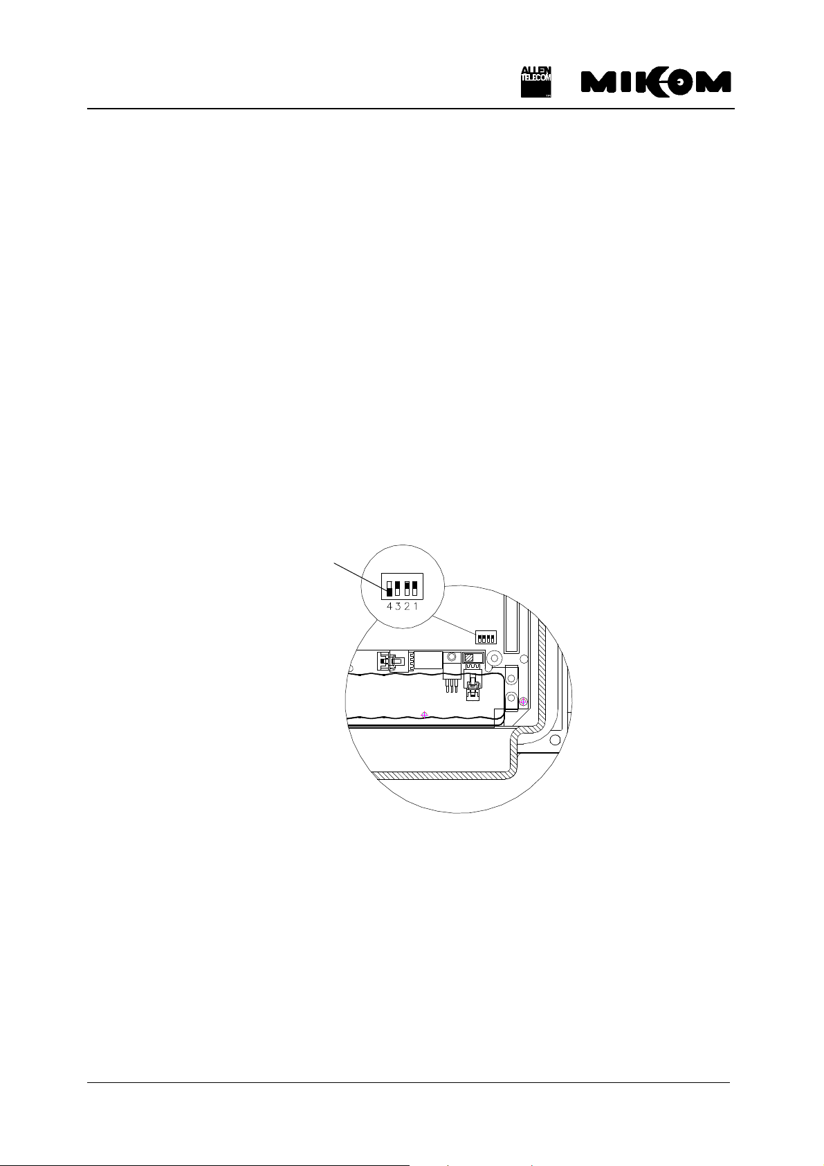
1. Set the DIP-Switch 4 to position ON on the control module.
DIP-Switch 4
figure 3-2 Position of DIP-Switch 4
1. To start upload procedure type:
Syntax: upload 1 ↵ or
upload 2 ↵
depending on which serial interface is available ( COM 1 or COM 2 ).
M0062A0B.doc Id.-No. 148964 Page 8 11.12.98

REP1009V1.xx
2. The copy procedure is running. You will be asked to continue by pressing any key. Now the
software download is in progress. The download lasts approximately 5 minutes in local
mode.
3. Software boot starts automatically.
4. Don’t forget to switch back the DIP-Switch 4 to position OFF.
M0062A0B.doc Id.-No. 148964 Page 9 11.12.98
REP1009V1.xx
ON
4 Running the software
4.1 Via PC or Laptop as terminal
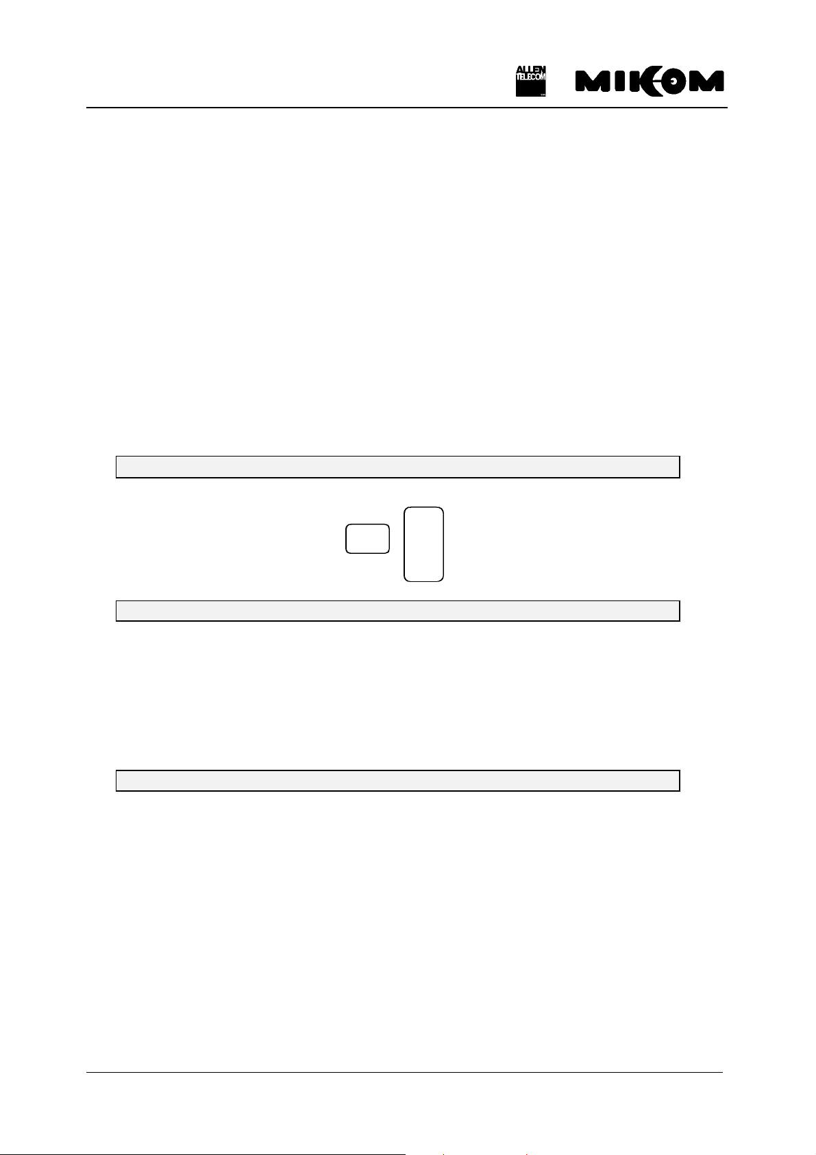
The local mode for settings via PC has to be set. Therefore the DIP-Switch 2 has to be at
position OFF.
OFF
figure 4-1 DIP-Switch 2 for local mode
F Note: Only if a Modem M1 is used DIP-Switch 2 has to be set.
A VT100 terminal or a PC with VT100 emulation can be connected to the control module
SM2009 by a standard RS232 cable, if necessary in connection with an adapter 9 to 25.
PC or Laptop - Control Module SM2009
9 contact SUB - D- Connector 9 contact SUB - D- Connector
male male
PC RS 232
PIN PIN
1 ) ( 1
2 ) ( 2
3 ) ( 3
4 ) ( 4
5 ) ( 5
6 ) ( 6
7 ) ( 7
8 ) ( 8
9 ) ( 9
figure 4-2 Cable connection
The following communication mode between control module and VT100 is set initially.
M0062A0B.doc Id.-No. 148964 Page 10 11.12.98
REP1009V1.xx
.
9600 baud - 8 bit - no parity -1 stopbit
These settings can only be changed after connection of the terminal. If all wanted settings have
been initialized and a modem has to be used it will be recommended to check whether the
settings comply with the capabilities of the modem and the line. Modifications are possible by
software commands.
F Note: Settings on the Repeater can be performed after the following procedure
only.
After connecting the PC to the Repeater, following procedure is necessary to get access to the
program.
MIKOM REPEATER MRx01A - SM2009 - SW: REP1009V1.xx
ENTER <.> <CR>
1. Step: Type the two keys ( . ) FULLSTOP and (↵) ENTER
You have to type the keys:
↵↵
2. Step: ENTER USER ID
You have to enter: UserID1 ↵
F Note: The input is case sensitive, no blanks. After three mistrial follows
disconnection.
3. Step: ENTER PASSWORD
You have to enter: P-word1 ↵
F Note: The input is case sensitive, no blanks. After three mistrials follows
disconnection.
M0062A0B.doc Id.-No. 148964 Page 11 11.12.98
REP1009V1.xx
4.2 Via modem
The Repeater will be delivered with a preset init string. This init string was used for internal
tests. In case no connection can be established check the local conditions and change the init
string if necessary.
Three different modem types are available
• PSTN modem ( DigiTel 34P ), line modem
• Siemens M1 for GSM900, wireless modem
• Motorola for GSM900 or GSM1800, wireless modem
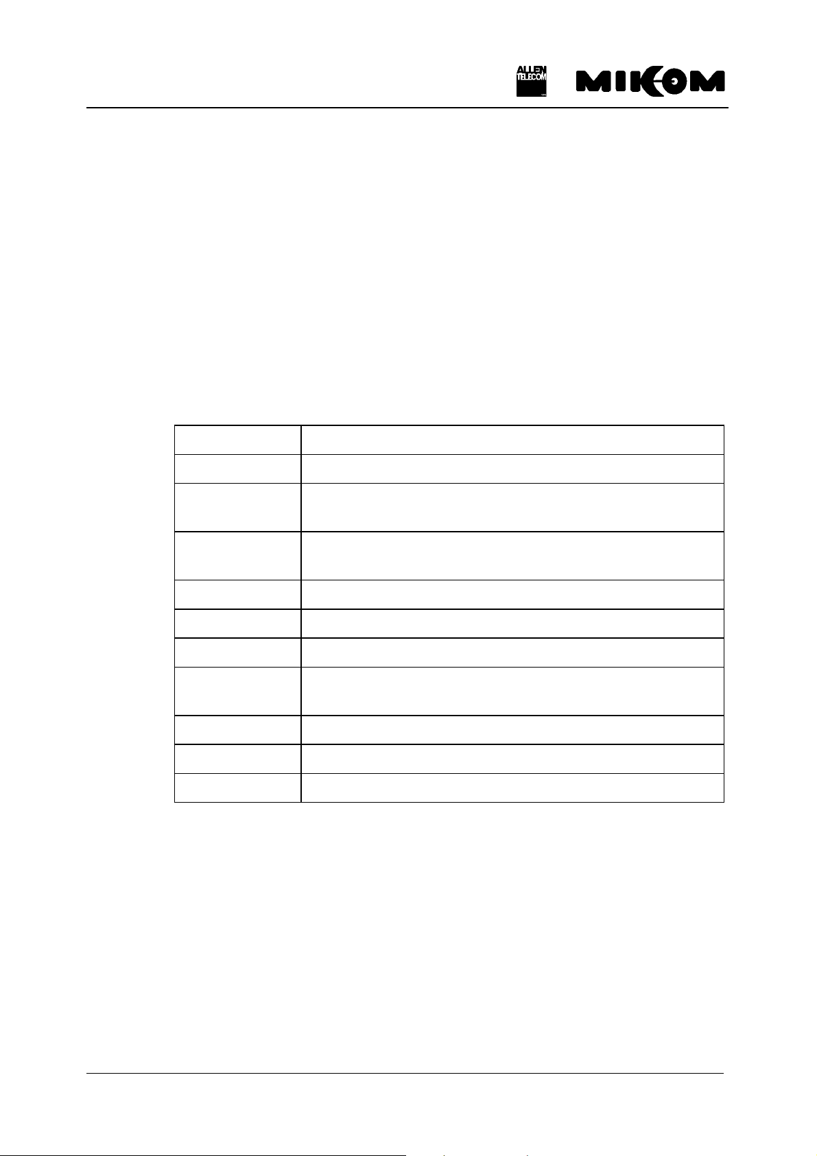
The following list contains the description of the AT commands:
&F Sets modem to factory configuration
E0 Echo OFF
S0=1 Auto answer ON; the GSM module / M1 modem goes off-
S7=60 Waiting time for connection after dialing; permissible values
B13 Setting to 9600 bps asynchronous mode
\ N6 Auto reliable operation
\ N0 Standard operation, no error correction
+CBST=7,0,1 Set bearer service type to 9600 bps. Non-transparent
X3 Not waiting for dial tone; usually used at PABX.
*P1 Switch ON phone
&K4 Enables XON / XOFF flow control
4.2.1 PSTN modem
hook after the first ringing signal.
are from 0 ... 60.
connection ( uses RLP )
Table 4.2-1 List of AT commands
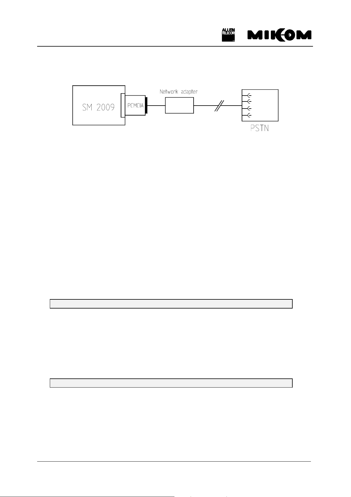
A Hayes compatible PSTN modem can be connected to the control module SM 2009 by the
control cable, which is subject of the delivery schedule.
The init string for the PSTN modem is:
AT&F X3 E0 S0=2
M0062A0B.doc Id.-No. 148964 Page 12 11.12.98
REP1009V1.xx
control module SM2009 - cable connection modem
PCMCIA
figure 4-3 Connection of control module and PSTN modem
The following communication mode between control module and VT100 is initially set for the
use of a Hayes-compatible modem.
9600 baud - 8 bit - no parity -1 stopbit
These settings can only be changed after connection of the terminal. If a different modem has
to be used or if the quality of the line does not allow to use the set parameters, the settings
have to be changed in PC mode. This is the same for all other parameters, which can be set
previously for modem mode by software.
F Note: Settings on the Repeater can be performed after the following procedure
only.
After connection to the Repeater following response appears on screen:
1. Step: ENTER USER ID
Response on the screen: ENTER USER ID:------
You have to enter: UserID1 ↵
F Note: The input is case sensitive, no blanks. After three mistrial follows
disconnection.
2. Step: ENTER PASSWORD
Response on the screen: ENTER PASSWORD:--------
You have to enter: P-word1 ↵
F Note: The input is case sensitive, no blanks. After three mistrials follows
disconnection.
M0062A0B.doc Id.-No. 148964 Page 13 11.12.98
 Loading...