

Andrew Wireless Innovations Group RPT-MR801, RPT-MR701 Functional description and integration instructions for Repeaters

Functional description
and
integration instructions
for Repeater using
band modules with
variable bandwidth.
M0050A0B.doc Id.-No. 148222 Page 1 of 12 11-Mar-99

Contents
1 Functional description........................................................................................3
2 Integrating a conversion module and programming communication bus
address......................................................................................................................5
2.1 What you have to know of your system before the setting..................................... 5
2.2 Setting the bus address of the module..................................................................... 6
2.3 Which CF to set?.....................................................................................................7
2.4 Attenuation setting.................................................................................................. 8
2.5 Required software commands.................................................................................9
3 Example.............................................................................................................10
4 Quick reference for experienced users...........................................................12
4.1 Frequency adjustment in UL and DL in module 1...............................................12
4.2 Frequency adjustment in UL and DL in modules 2/3/4....................................... 12
4.3 Attenuation............................................................................................................12
M0050A0B.doc Id.-No. 148222 Page 2 of 12 11-Mar-99
1 Functional description
The band module with variable bandwidth can be set to a desired centre frequency and to a
desired bandwidth.
The explanation how it works is made with reference to the following figures and exemplary
values for frequencies, bandwidths and levels.
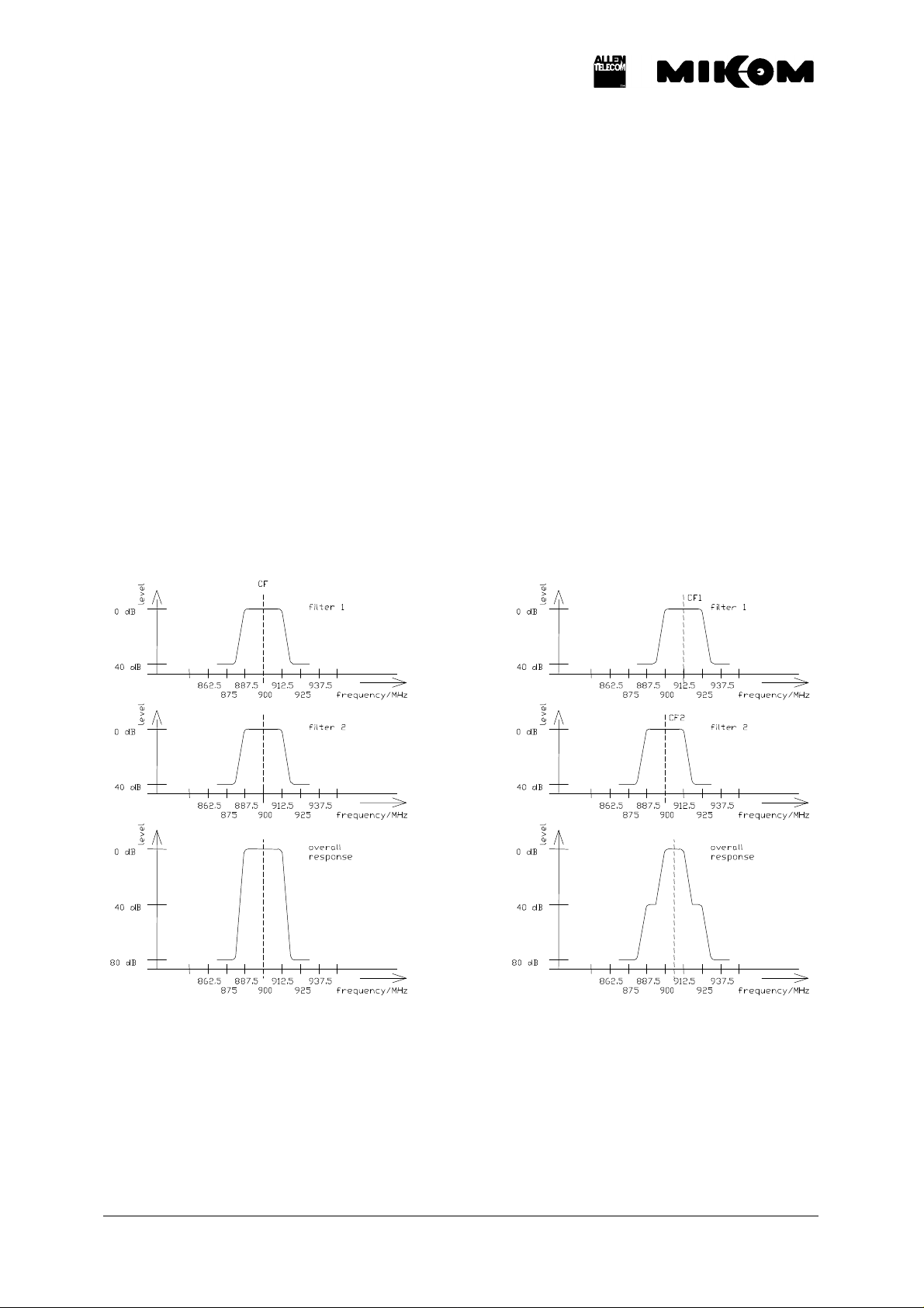
There are two filters in one link (UL or DL) in series in the band module which can be set to a
defined centre frequency. In the example we have two filters with a bandwidth of 25 MHz
each and for demonstration purposes the frequency range is 870 to 940 MHz.
In Fig. 1 we see that filter 1 and filter 2 are both set to a centre frequency (CF) of 900 MHz.
The resulting overall response of the module is thus a 25 MHz band with a centre frequency
of 900 MHz (⇒ frequency range from 887.5 MHz to 912.5 MHz). The attenuation in the stop
band of one filter was assumed to be 40 dB. Thus, the overall attenuation of the module is
80 dB.
Fig. 1 Fig. 2
M0050A0B.doc Id.-No. 148222 Page 3 of 12 11-Mar-99

In Fig. 2 we have the same filters but this time with different centre frequencies. The centre
frequency of filter 1 is this time 912.5 MHz and the centre frequency of filter 2 is again
900 MHz. Consequently, we get another overall response of the module as can be seen in
fig. 2. Filter 1 limits the frequency range towards lower frequencies and filter 2 towards
higher frequencies. The resulting response is thus an attenuation of 80 dB up to 881.25 MHz,
40 dB up to 893.25 MHz, 3 dB bandwidth is 12.5 MHz from 900 MHz to 912 MHz, 40 dB
attenuation from 918.75 MHz and 80 dB from 931.25 MHz. (Values exemplary!)
It is shown in the following how the centre frequency and the bandwidth of the module can be
set to desired values.
M0050A0B.doc Id.-No. 148222 Page 4 of 12 11-Mar-99
 Loading...