


TIA-136 DIGITAL
EAC-2100 Manual
- - - D R A F T - - -
Order No. xx-xxx-xx
Issue 02/01
Copyright 2001
All Rights Reserved

Installer Warning:
F Note:
HEALTH AND SAFETY WARNINGS
Any over-the-air radiated use of this product is intended to be used with either
Roof Top (Building-mount) or Pole Mounted (Non-building-mount) Antennas.
Antenna installation must conform within the following guidelines to meet FCC
RF exposure limits. Otherwise a environmental evaluation is required if:
Narrowband PCS (subpart D): Non-building-mounted antennas: height above ground
level to lowest point of antenna < 10m Radio (Part 24) and total power of all channels >
1000 W ERP (1640 W EIRP).
Building-mounted antennas: Total power of all channels > 1000 W ERP (1640 W EIRP).
Cellular Radiotelephone Service (Part 22, subpart H): Non-building-mounted antennas:
height above ground level to lowest point of antenna < 10m Radio (Part 22) and total
power of all channels > 1000 W ERP (1640 W EIRP).
Building-mounted antennas: Total power of all channels > 1000 W ERP (1640 W EIRP).
For clarification, please refer to FCC rules, 47 CFR ch. I, part 1.1307
The electrical installation has to be performed in accordance with the safety
regulations of the local authorities. Due to safety reasons, the electrical installation
must be performed by qualified personnel. Subsequent installation, commissioning
and maintenance activities that require the unit to be powered with the cover open
shall only be carried out by suitably qualified personnel.
F Note:
F Note:
The grounding of the Unit has to be performed in accordance with local electrical
codes. A grounding bolt is provided at the bottom of the cabinet in order to connect
the earth bonding cable.
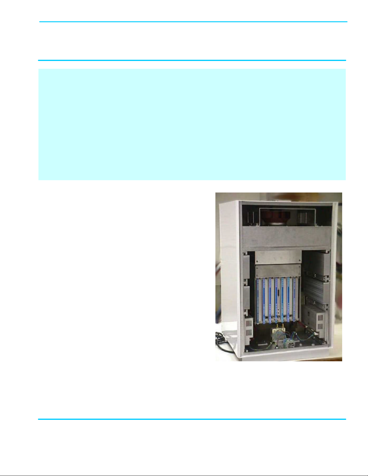
The Unit weighs 210 lb (95 kg). Make sure that a suitable mounting surface is used
if it is to be wall-mounted, or an adequate floor surface to support the weight is
available if it is to be pedestal-mounted. Also, make sure that adequate lifting tools
are available for placing the unit either on its wall bracket or on the pedestal.

Field Support
If you need technical assistance with the EAC-2100, contact
MIKOM US, an Allen Telecom Company at one of the following
telephone numbers:
Extend-A-Cell HOTLINE: (800) 800-7465
or (804) 386-5340

LIMITED WARRANTY
MIKOM, an ALLEN TELECOM COMPANY, ("ALLEN TELECOM") warrants, on the terms and conditions hereto set forth,
all products manufactured by it to be free under normal use and service from defects in materials and workmanship for a period
of one (1) year from the date of shipment, to the first consumer (the "Warranty Period").
ALLEN TELECOM's obligation under this Limite d Warranty is limited to prompt repair or replacement of the product,
at its option, without charge, at an authorized ALLEN TELECOM dealer or at the factory of ALLEN TELECOM in
Forest, Virginia, when the product is returned to an authorized dealer or to the factory with all transportation charges
prepaid and examination of the product shall disclose it to have been defective in the respects aforesaid during the
Warranty Period.
The Limited Warranty shall not be extended beyond its original term with respect to any part or parts repaired or replaced by
ALLEN TELECOM hereunder.
The Warranty Period shall not apply to any product which has been repaired or altered in any manner by anyone other than
ALLEN TELECOM or an authorized outlet of ALLEN TELECOM, or if the defect, malfunction or failure of the product was
caused by damage by lightning, flood or other acts of nature or by power surges, or from unreasonable use, or from improper
installation or application, or to any product which has not been maintained or used in accordance with the operating
specifications set forth in ALLEN TELECOM's written instructions.
IMPLIED WARRANTIES OF MERCHANTABILITY OR FITNESS FOR ANY PARTICULAR PURPOSE ARE
LIMITED IN DURATION TO THE WARRANTY PERIOD SPECIFIED ABOVE.
UNDER NO CIRCUMSTANCES SHALL ALLEN TELECOM BE LIABLE FOR ANY CONSEQUENTIAL
DAMAGES FOR BREACH OF THIS WARRANTY OR OF ANY IMPLIED WARRANTY.
Some states do not allow limitation on how long an implied warranty lasts, so the above limitation may not apply to you.
Some states do not allow the exclusion or limitation of incidental or consequential damages, so the above limitation or
exclusion may not apply to you. This Warranty gives you specific legal rights, and you may also have other rights which
vary from state to state.
ALLEN TELECOM neither assumes nor authorizes any person to assume for it any obligation or liability other than as herein
expressly stated.
1900 MHz
coverage
cells. Isolation requirements are also minimized due to the translating
136 carriers with channel selective RF cards. The
The EAC2100 uses state of the art DSP technology coupled with a high speed Power PC processor to decode the
The EAC2100 is software configurable and remotely manageable via a modem dial up link. Call traffic statistics are
Frequency Translating Channel Selective
HIGH POWER TRANSLATING CHANNEL SELECTIVE REPEATER
for TIA/EIA-136 PCS Networks
MIKOM’s EAC2100 repeater is designed to provide wide area coverage for TIA/EIA-136, 1900 MHz networks.
High power and gain, achievable due to the intelligent F1 to F2 architecture, allow the EAC2100 to provide
extension normally available only from macronature of the repeater. The repeater boosts up to four TIA/EIAEAC2100’s architecture is frequency agile both on the donor and coverage channels.
TIA/EIA-136 message stream. The EAC2100 fully supports the TIA/EIA-136 Stand ard and its feature set.
logged and reported over a rolling weekly window. All setup parameters are software settable via the local port or dialup link. The repeater is designed for easy installation and outdoor use.
•
Operation
• 2 or 4 Channel Capacity
• High Forward Output Power
• 12.5 Watts each for 4 Channels
• 25 Watts each for 2 Channels
• Multiple Cabinets for Up to 8 Channels
• Full TIA/EIA-136 Feature Set including:
• Extended Battery Life (sleep mode)
• SMS
• Calling Line and Party ID
• Over the Air Activation
• Authentication
• Registration
• Mobile Assisted Hand Off (MAHO)
• Easy Field Upgrades and Maintenance
• Receive Diversity Standard
1900 MHz
Manufactured under one or more of the following
patents: 4,941,200 / 4,849,963 / 4,754,495
4,704,733 / 5,541,979 and/or patents pending or
The Federal Communications Commission has not
yet approved this device. This device is not, and
may not be, offered for sale or lease, or sold or
leased until the approval of the FCC has been
HIGH POWER TRANSLATING CHANNEL SELECTIVE REPEATER
for TIA/EIA-136 PCS Networks
AC Power / Current Requirements
120/240 VAC 50/60 Hz (Auto -ranging)
10A @ 240 VAC
DC Power / Current Requirements
19-30 VDC (nominal 24 VDC)
Maximum 40A @ 27.6 VDC
Standby 10A @ 27.6 VDC
Battery Backup (customer provided)
4 hours typical using 100 AH batteries
Temperature Range
-30°C to +55°C Operating
-40°C to +75°C Storage
Relative Humidity
95% maximum at +50°C
Antenna Connectors
7/16 DIN, N female remote access
Channel Capacity (2 versions available)
2 or 4 RF Channels
Weight 210 lb./ 95 kg
Cabinet Dimensions (H x W x D)
36” x 21.5” x 23”
91 x 55 x 59 cm
General Specifications
RF Specifications
Gain >120 dB (excluding antenna gain)
Channel Bandwidth (TDMA)
Meets TIA-136-280-B BTS requirements
Programmable Frequency Control
Spacing 30 kHz
Bands: BDE, CEF
Channels 1-1999
Output Frequency Accuracy
TIA/EIA-136 synchronized to donor
Minimum Input Donor Signal Level
-75 dBm
Rated Output Power at Antenna Connector
Forward: 25W/ch., 2 channel
12.5W/ch., 4 channel
Reverse: +20 dBm per channel
Sensitivity (Reverse path)
Meets TIA-136-280-B BTS requirements
RSSI Range
Forward: -100 to –20 dBm
Reverse: -120 to –40 dBm
applied for in the United States and Canada
obtained.

Contents
Page
List of Figures .......................................................................................................................vi
Quick Start Checklist...........................................................................................................vii
1. Introduction................................ ............................................................................1-1
1.1 About This Volume....................................................................................1-1
1.1.1 Contents................................ ........................................................1-1
1.1.2 Terminology................................ ..................................................1-3
1.2 About the TIA/EIA-136 EAC-2100.......................................................1-4
1.2.1 Use of Boosters................................................................ .............1-4
1.2.2 Frequency Allocation....................................................................1-4
1.2.3 EAC-2100 Operation....................................................................1-4
2. Preliminary Decisions................................ ............................................................2-1
2.1 Introduction.................................................................................................2-1
2.2 Use of Multi-hop Configuration or Multi-donor Units......................2-2
2.3 Site Requirements.......................................................................................2-2
2.3.1 Location.........................................................................................2-2
2.3.2 AC Service ....................................................................................2-3
2.3.3 Space................................ .............................................................2-3
2.3.4 Mounting Surface................................................................ ..........2-4
2.4 Antennas................................ .....................................................................2-4
2.4.1 Type...............................................................................................2-5
2.4.2 Placement ................................ .....................................................2-6
2.4.3 Measuring Signal Level and Isolation ..........................................2-9
2.5 Selecting Channels....................................................................................2-11
2.5.1 Identifying the Donor DCCH Channel .......................................2-11
2.5.2 Selecting a Boosted DCCH Channel ..........................................2-12
2.5.3 The Revertive DCCH Channel Option.......................................2-13
2.5.4 The Substitute DCCH Channel................................ ...................2-13
• Disabling the Substitute DCCH Channel ............................2-14
• Enabling the Substitute DCCH Channel..............................2-14
2.5.5 Selecting the Directed Retry Channels .......................................2-15
2.5.6 Selecting Donor DTC Channels..................................................2-16
2.5.7 Selecting Boosted DTC Channels...............................................2-17
AMPS EAC-2100 Manual: Draft 02/01) Page i

Contents
Page
3. Installing the Hardware ........................................................................................3-1
3.1 Introduction.................................................................................................3-1
3.2 Mechanical Installation ...............................................................................3-4
3.2.1 Uncrating the Equipment..............................................................3-4
3.2.2 Mounting the Cabinet....................................................................3-4
3.2.3 Securing the Doors................................................................ ........ 3-5
3.3 Connecting the EAC-2100 to ac Power .....................................................3-6
3.4 Installing the Antennas ................................................................ ...............3-6
3.4.1 Connecting the Antennas ..............................................................3-7
3.5 Connecting External Alarms/Controls (Optional)................................ ..... 3-8
4. Setting Up for Initial Operation ...........................................................................4-1
4.1 Introduction.................................................................................................4-1
4.2 Powering Up the EAC-2100 ...................................................................... 4-3
4.3 Powering Down the EAC-2100 .................................................................4-4
4.4 Connecting a Local Terminal......................................................................4-4
4.5 Becoming Familiar with System Commands .............................................4-6
4.5.1 Basic Commands...........................................................................4-6
4.5.2 Using the SET Menus................................................................4-10
4.6 Setting Initial Parameters.........................................................................4-12
4.6.1 Checking System Status.............................................................4-12
4.6.2 Entering the Site ID.................................................................... 4-13
4.6.3 Setting the Donor DCCH Channel.............................................4-14
4.6.4 Setting the Boosted DCCH Channel..........................................4-15
4.6.5 Setting the Directed Retry Channels.......................................... 4-15
4.6.6 Setting the Donor DTC Channels..............................................4-16
4.6.7 Setting the Boosted DTC Channels...........................................4-18
4.6.8 Programming Alarms and Thresholds................................ .......4-18
4.6.9 Programming the Modem Mobile MIN,
Mobile Power Step, and Passwords ............................. 4-24
4.7 Tuning Transmitter Combiner and Setting Output Power ......................4-25
4.7.1 Adjusting Combiners and
Power Levels for PAs 1−5 and 7−11...........................4-25
4.7.2 Adjusting the PA 6 Power Level................................................4-28
4.7.3 Setting Reverse Path Output Power (If Necessary)................... 4-29
4.7.4 Setting PA Power Low Alarm Points......................................... 4-30
4.7.5 Setting Time and Report Values................................................4-31
AMPS EAC-2100 Manual: (Draft, 02/01) Page iii

Contents
Page
5. Installing the Remote Link....................................................................................5-1
5.1 Introduction.................................................................................................5-1
5.2 Setting Up Service .....................................................................................5-3
5.3 Programming the Mobile Radio................................................................ .5-4
5.4 Checking Out the Mobile ................................ ...........................................5-4
5.5 Testing the Remote Link................................................................ ............5-5
5.5.1 EAC-2100 Answering ................................................................ ..5-5
5.5.2 EAC-2100 Originating.................................................................5-6
6. Optimizing Performance ......................................................................................6-1
6.1 Introduction.................................................................................................6-1
6.2 Determining Hand-in and Hand-back Thresholds......................................6-1
6.3 Setting Hand-in and Hand-back Thresholds ................................ ..............6-2
List of Figures
Figures Page
1-1. Important Terms Used in This Manual................................ ....................................1-3
1-2. System Operation................................................................ .....................................1-5
2-1. Pre-Installation Checklist .........................................................................................2-1
2-2. Recommended Space................................................................................................2-3
2-3 Typical Antenna Installation ....................................................................................2-8
2-4 Antenna Isolation v. Horizontal Separation.............................................................2-9
2-5 Antenna Isolation v. Vertical Separation...............................................................2-10
3-1. Hardware Installation Checklist...............................................................................3-2
3-2. EAC-2100, Front View (Door Removed)................................................................3-2
3-3. EAC-2100, Back View (Door Removed)................................................................3-3
3-4. Outdoor Cabinet Footprint.......................................................................................3-4
3-5. Antenna Connectors................................................................ .................................3-7
3-6. External Alarm/Control Connector Pin Out................................ ............................3-8
3-7. Electrical Specifications for Inputs and Outputs................................ .....................3-9
3-8. Typical Wiring for External Inputs and Outputs...................................................3-11
4-1. Setup Checklist.........................................................................................................4-2
4-2. EAC-2100 Breakers................................................................................................ .4-3
4-3. Breaker Locations.....................................................................................................4-3
4-4. Location of Local Terminal Connector....................................................................4-4
4-5. Command Definitions ..............................................................................................4-6
4-6. System Commands................................ ...................................................................4-8
4-7. SET Command Menu Map ....................................................................................4-11
4-8. Combiner Cavity ...................................................................................................4-25
4-9. Location of PA Power Potentiometer.....................................................................4-27
5-1. Remote Link Installation Checklist..........................................................................5-3
AMPS EAC-2100 Manual: (Draft, 02/01) Page iii


Quick Start Checklist
Programming Initial Parameters (See Sections 4, 5, and 6)
1. Type SSS <CR>. (Nothing should show DISABLED. If anything shows
disabled, refer to Appendix A, Troubleshooting Guide.)
2. Type ALA <CR>. (There should be no alarms. If there are any OUT OF
SERVICE or memory alarms, refer to Appendix A.)
3. Type SET <CR> and go into submenu C, System Parameters.
4. Enter submenu A and program the site ID.
5. Enter submenu B and program the donor and boosted DCCH channels.
Decide how the DCCH control channel is to act when all channels are busy.
6. Enter submenu C and program the boosted DTC RF channel numbers for
channels 2–4.
7. Program the donor DTC RF channels into list.
8. Enter the Modem Control submenu D and program the modem mobile MIN
that has been assigned. Calls made to and from this number will not be
transferred to the booster, but will be trapped -out and handled directly by the
donor. Also set the modem mobile power step to the desired level.
9. Use <CTRL> X to exit the SET menu completely. Press <CR> at the
question prompt.
Continued . . .
AMPS EAC-2100 Manual: (Draft, 02/01) Page

Quick Start Checklist
Programming Initial Parameters (Continued)
12. From the command entry level >, use the TIM command to set the date and
time.
13. From the command entry level >, enter DCS=0, DCH=0, and ALA=0 to reset
the report values.
Completing the Installation
1. Connect the antennas. The unit is now operational!
2. Type SCS <CR> and make some calls. You will see your MIN displayed on
call originations and answers.
3. Connect the handset to the connector on the front of the mobile shelf (see
Section 5).
4. Program hand-in/hand-back thresholds as desired (see Section 6).
5. After completing installation and setup, secure the cabinet door.
AMPS EAC-2100 Manual: Vol. I, Installation Procedures (27-7655-2, 12/95) Page viii

1.1 About This Volume
1.1.1 Contents
This volume, pertaining to the TIA/EIA-136 EAC-2100, contains detailed procedures for
installing and operating the EAC-2100. This volume has been divided into a Quick Start
Checklist and 12 sections, described below.
Introductory Information
• Quick Start Checklist: Brief summary of installation and setup procedures.
• Section 1. Introduction: Contents of this volume, key terms, and a general introduction to
the TIA/EIA -136 EAC-2100.
• Section 2. Preliminary Decisions: Factors to consider before you begin installation.
Basic Installation
• Section 3. Installing the Hardware: Procedures for mechanical, electrical, and antenna
installation and connection of external alarms or controls.
• Section 4. Setting Up for Initial Operation: Procedures for powering up the system,
connecting a local terminal, programming parameters, tuning the transmitter combiner, and
setting output power.
• Section 5. Installing the Remote Link: Procedures for setting up, programming, and
checking out the mobile, and testing the remote link.
• Section 6. Optimizing Performance: Procedures for setting hand-back and hand-in
thresholds to optimize booster performance.
2. Preliminary Decisions
1. Introduction
AMPS EAC-2100 Manual: (Draft, 02/01) Page 1-1

2. Preliminary Decisions
Terminology
Figure 1-1 lists key terms used in this volume. Additional terms and acronyms are defined in the
Glossary.
Figure 1-1. Important Terms Used in This Manual
Term Definition
TDMA
Boost
Booster
Booster Coverage Area
Donor Cell Site
Donor DCCH Channel
Boosted DCCH Channel
EAC-2100
Forward Path
Repeater Synonymous with booster, usually applied to boosters that
Time Division Multiple Access. Commonly used to refer to the
TIA/EIA-136 digital cellular system.
To receive, amplify, and reradiate signals to fill in weak coverage
areas.
A system that boosts or repeats
The area where subscribers obtain coverage through the booster.
The cell site in communication with the booster.
The DCCH channel used between the cell site and the booster (and
all the subscribers in direct contact with the cell site).
The DCCH channel used between the booster and the subscriber in
the booster coverage area (a different frequency than the donor
DCCH channel).
The trademarked name for a booster made by MIKOM US, an
ALLEN TELCOM Company.
The path taken by the RF signal transmitted by the donor cell,
which is received, amplified, and reradiated by a booster and
received ultimately by a subscriber in the booster coverage area.
translate frequencies. The EAC-2100 is type-accepted as a
repeater.
Reverse Path
The path taken by the RF signal transmitted by a subscriber mobile
in the booster coverage area, which is received, amplified, and
reradiated by a booster and received ultimately by the donor cell
site.
AMPS EAC-2100 Manual: (Draft, 02/01) Page 1-2

1.2 About the TIA/EIA-136 EAC-2100
This section provides a brief overview of how the EAC-2100 operates. For a more detailed discussion,
refer to Volume 3, Technical Information.
1.2.1 Use of Boosters
Cellular telephone systems transmit signals in two directions between cell sites and subscriber
telephones within the signal coverage area. The signal path from the cell site to the subscribers
is called the forward path, and the path from subscribers to cell site is the reverse path.
If weak signal transmissions occur within the coverage area because of terrain obstructions, a
relatively inexpensive way to extend transmission range is to install a signal booster that
receives the signal, amplifies it, and reradiates it. (See Figure 1-2.)
1.2.2 Frequency Allocation
TIA/EIA-136 cellular systems use 1850 -1910 MHz for reverse and 1930-1990 MHz for
forward transmissions. These frequency bands are divided into A, B, C, D, E, & F blocks.
1.2.3 EAC-2100 Operation
The EAC-2100 booster is available in either a two-channel or a four-channel configuration.
Each RF channel is capable of handling three full-rate TDMA channels. Therefore, a fourchannel EAC-2100 can provide one DCCH channel and 11 DTC DTC channels.
Also, two EAC-2100 boosters may be operated together to provide up to eight RF-channel
operation (1 DCCH plus 23 DTC DTC channels). A digital control cable connects the two
cabinets together to allow one cabinet to handle the DCCH duties.
A block diagram of the EAC-2100 is shown in figure 1-2. Up to four 800 MHz TDMA
modules are used. These modules are similar to those used in the EAC-2000, with the main
difference being that they have a lower output power level in the reverse direction. Like the
EAC-2000, these modules provide the frequency translation feature necessary to allow highgain repeater operation.
Block converters are used to convert the PCS band to the 800 MHz band, and likewise the 800
MHz band to the PCS band. A Forward Block Converter and a Reverse Block Converter is
used. Each block converter has its own synthesizer and local-oscillator control for performing
the block conversion process.
1.2.3 EAC-2100 Operation (Continued)
2. Preliminary Decisions
AMPS EAC-2100 Manual: (Draft, 02/01) Page 1-3
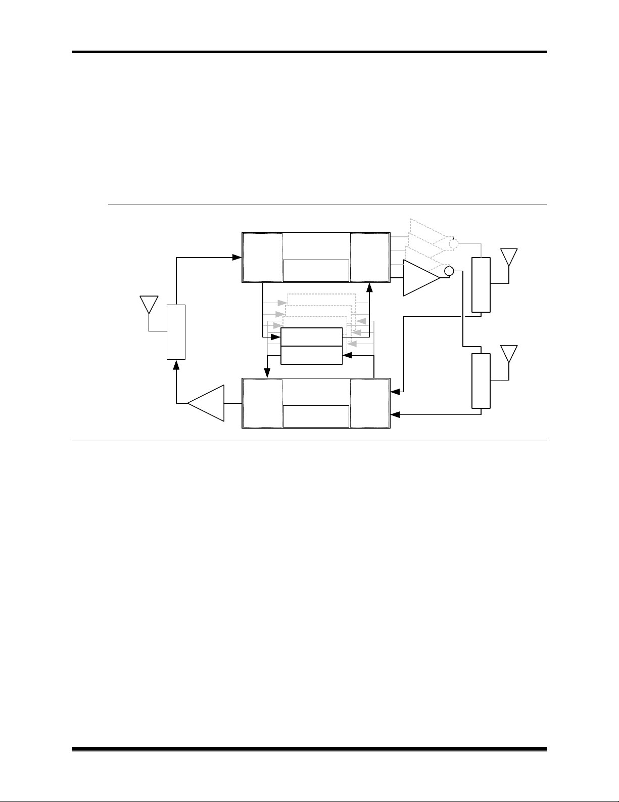
The Forward Block Converter converts the 1930-1990 MHz signals from the donor cell site to
the 870-890 MHz band. The 870-890 MHz block is fed to the 800 MHz TDMA RF modules
for signal processing. The outputs of the 800 MHz modules are individually converted back to
the 1930-1990 MHz band for subsequent transmission to the repeater coverage area. Since the
PCS band is wider than the 800 MHz tuning range of the 800 MHz RF modules, the Block
Converters cover the PCS band in three 20 MHz segments.
Figure 1-2. System Block Diagram
870-890
825-845
CONVERTER
CONVERTER
DOWN-
4-WAY
TDMA RF MODULES
COMBINER
4-WAY
& UP-
BLOCK CONV.
SYNTHESIZER &
800 MHz FWD
800 MHz FWD
800 MHz REV
800 MHz FWD
800 MHz REV
800 MHz REV
BLOCK CONV.
SYNTHESIZER &
DONOR
ANT
1930-1990
DUPLEXER
DONOR
1850-1910
LINEAR
Likewise, the Reverse Block Converter converts the 1850-1910 MHz signals received from the
subscribers to the 825-845 MHz band. Operation is similar to the Forward Block Converter
except that an RF switching matrix is employed to allow M1/M2 antenna diversity selection.
Another difference is that the reverse signal outputs from the 800 MHz modules are linearly
combined and then up-converted as a group to the 1850-1910 MHz band.
A 50-watt linear PA is used for each forward PCS carrier. The PAs are paired and combined in
two 3-dB hybrid combiners. One hybrid combiner output is connected to the TX port of the M1
duplexer, and the other output is connected to the M2 duplexer.
A 1-Watt composite (20 watts peak) PCS linear power amplifier is used for transmitting the
reverse path signals back to the donor.
The EAC-2100 comes in either a low-split or a high-split configuration. The low-split
configuration covers the A, D and B bands, while the high-split configuration covers the E, F,
and C bands. This is summarized in the table below:
1.2.3 EAC-2100 Operation (Continued)
FORWARD
L.O.
800 MHz FWD
800 MHz REV
REVERSE
L.O.
CONVERTER
4-WAY UP-
CONVERTER
4-WAY DWN
DIVERSITY
SWITCH &
2. Preliminary Decisions
1930-1990
45W
45W
45W
45W
1930-1990
1850-1910
1850-1910
M1 DUPLEXER
M2 DUPLEXER
M1 ANT
M2 ANT
AMPS EAC-2100 Manual: (Draft, 02/01) Page 1-4

2. Preliminary Decisions
Model: Low Split High Split
Band: A, D & B E, F, & C
Channel Number Range: 1-1167 833-1999
Forward Frequency Range: 1930-1965 MHz 1955-1990 MHz
Reverse Frequency Range: 1850-1885 MHz 1875-1910 MHz
Note that there is some overlap between the low split and high split bands. This is due to the
characteristics of the duplexers.
Boosting DCCH Channels. The EAC-2100 monitors the PCS donor DCCH channel to obtain
system-specific information. It generates a DCCH data stream and transmits it on a different
DCCH channel that is assigned for repeater use. Subscribers that are unable to receive the
original channel then lock onto the boosted DCCH channel and communicate with the cell site
through the booster. Adding the repeated DCCH channel to the donor’s neighbor list will allow
subscribers in the repeater coverage area to lock onto the repeater and to receive or place calls.
Boosting DTC Channels. The amplifiers for repeating DTC channels are enabled as needed
when digital traffic channel (DTC) activity is detected in the repeater coverage area. The EAC2100 identifies subscribers in the repeater coverage area by two methods: one for identifying
subscribers that place or answer calls from within the repeater coverage area and another for
identifying subscribers that enter the area with a call in progress.
When a call is placed or answered from within the repeater coverage area, the following
sequence occurs:
1. The subscriber accesses the reverse boosted DCCH channel. The EAC-2100 receives the
access, then accesses the reverse donor DCCH channel.
2. The EAC-2100 waits for the corresponding DTC designation message on the forward
channel.
3. The EAC-2100 modifies the DTC designation message by substituting one of its boosted
DTC RF channels for the donor DTC assignment, thus sending the subscriber to one of the
boosted DTC RF channels.
4. A repeat path is set up between the subscriber and the primary donor cell site, with the
subscriber operating on the boosted DTC RF channel, the donor operating on the donor
DTC, and the EAC-2100 translating and boosting between the two.
To identify subscribers that may drive into the boosted coverage area with a call in progress, the
EAC-2100 scans the donor DTC RF channels on a per-time-slot basis and maintains a Received
Signal Strength Indicator (RSSI) average for each time-slot. If the average RSSI exceeds a
preset threshold, the EAC-2100 hands the subscriber to one of the boosted DTC channels.
AMPS EAC-2100 Manual: (Draft, 02/01) Page 1-5

2. Preliminary Decisions
1.2.3 EAC-2100 Operation (Continued)
Boosting to Multiple Donor Cells. To provide for situations in which in-progress calls may be
linked to various neighboring cell sites (multi-donor operation), the system allows for entry of
different donor DTC RF channel lists. For handing in subscribers, note that the donor
antenna system at the EAC-2100 must be specifically designed for multiple donor
operation.
In addition, the MAHO feature of TIA/EIA -136 systems allows the cellular system to hand-off
the subscriber to neighboring cells even if the neighboring cell does not have a propagation path
to the EAC-2100. No additional hardware is required at these neighboring cells. The only
requirement is that these neighboring cells must have their “locate-and-verify” option disabled.
If the booster is adjacent to a single cell site, that cell site is referred to as the donor cell, and the
DCCH channel of that cell site is the donor DCCH channel. The DTC RF channels used in the
donor cell may be entered into the donor DTC channel list with the DVCC of that cell site to
handle subscribers that drive between the donor and booster with a call up.
If the booster is adjacent to several cell sites and there are donor antennas pointing at these cell
sites, the DCCH channel of one of the cell sites is chosen as the donor DCCH channel, and this
cell is then referred to as the primary donor cell. The DTC RF channels of all the neighboring
cells are entered into the scan list with the DVCC of the neighboring cells. Signal strength at
the D1 antenna port must be balanced (to within the cell system hand -off threshold
window) from all neighboring cell sites.
Also, the DCCH channel that is assigned to the EAC-2100 must be included in the DCCH
neighbor list that is sent out by the dono r. This is necessary to allow the subscriber to quickly
find the boosted DCCH channel.
Calls placed or answered from within the booster coverage area (identified by decoding the data
streams) are repeated back to the primary donor cell. Calls handed in (identified by channel and
time-slot scanning) are repeated back to the cell on which the call was in progress.
Driving away from the Repeater to The Donor. The EAC-2100 monitors for weak
subscriber RSSI, and also monitors the MAHO information that is being sent back from the
subscriber handset. If the MAHO information indicates that the subscriber is hearing the donor
DCCH channel at an adequate level, then the EAC-2100 will send a hand-off message to that
subscriber to return him to the donor DTC RF channel.
Driving away from the Donor and the Repeater. For this case, the TIA-136 MAHO feature
allows the donor to hand the subscriber to an adjacent cell. The donor determines if the
subscriber is a candidate for hand-off by evaluating the DCCH channel levels in the MAHO list.
If the subscriber is reporting an adjacent DCCH that is stronger than what it is reporting from
the donor DCCH, then the system will issue a hand-off message to that subscriber.
Note that for adjacent cell site handoff to work pro perly, the system will have to be configured
such that:
AMPS EAC-2100 Manual: (Draft, 02/01) Page 1-6

2. Preliminary Decisions
A. The reverse path signal level from the repeater is set such that it will trigger
MAHO requests from the boosted subscribers,
B. The donor site MAHO list must include all cell sites that are within overlapping
coverage of the repeater, and
C. Those adjacent cell sites that are within overlapping coverage with the repeater
must have any secondary or backup verification feature (such as subscriber locate
and verify before allowing handoff) disabled. Secondary verification may be useful
in a densely populated system where intermod may false the subscriber’s MAHO
readings, but is not necessary in the rural environments for which the EAC-2100 is
intended.
If there is no adjacent cell site to which the donor can direct the subscriber to, then the EAC2100 will maintain the boost path for as long as it can.
Ending the Boost. The EAC-2100 will terminate a boosted call under the following conditions:
A. Loss of signal, either from the donor or the subscriber,
B. The subscriber has terminated the call,
C. The land-side or donor has terminated the call, or
D. The EAC-2100 has handed the subscriber to the donor DTC RF channel, or
E. The donor has handed the subscriber (through the boosted DTC RF channel) to an
adjacent cell site.
AMPS EAC-2100 Manual: (Draft, 02/01) Page 1-7

2. Preliminary Decisions
AMPS EAC-2100 Manual: (Draft, 02/01) Page 1-8


2100 weight and space requirements. (Secs.
Directed retry channels (at least one of the six directed retry channels
2. Preliminary Decisions
2.1 Introduction
Before the EAC-2100 can be installed, preliminary decisions must be made about the following:
• Use of Multi-hop configuration
• Booster site
• Antenna placement
• DCCH and DTC channels to be used
As an installer, you ma y be involved in some or all of these decisions. The checklist in Figure 2-1
provides a brief overview of preparations to be made prior to installing the EAC-2100.
Figure 2-1. Pre-Installation Checklist
q 1. Coverage area and distance from base station identified. (Sec. 2.3.1)
q 2. Distance to donor entered (in kilometers).
q 2. Electrical service verified for installation site. (Sec. 2.3.2)
q 3. Site selected in accordance with EAC-
2.3.3 and 2.3.4)
q 4. M1, M2, D1 and mobile modem antennas selected and installed. (Sec. 2.4)
q Minimum vertical separation of antennas achieved.
q 5. Antenna isolation and signal levels from the cell site measured. (Sec. 2.4.3)
q 6. RF channels selected: (Sec. 2.5)
q Donor DCCH channel
q Boosted DCCH channel
q
should be assigned)
Checklist
AMPS EAC-2100 Manual: (Draft, 02/01) Page 2-2

2. Preliminary Decisions
2.2 Use of Multi-Hop™ Configuration or Multi-Donor™ Units
Multi-hop operation involves setting up two or more EAC-2100 units to operate together in a line. This
configuration is described in greater detail in Section 7.
Note that no additional equipment is required at neighboring cell sites along the multi-hop path. The
MAHO feature of the TIA/EIA -136 system allows the cellular system to hand off a subscriber from the
EAC-2100 multi-hop coverage area to any neighboring cell.
If either of these arrangements is to be used, system parameters will need to be set accordingly.
2.3 Site Requirements
The site chosen for the EAC-2100 must meet requirements related to location, electrical service, space,
and mounting surface, as described below.
2.3.1 Location
Distance from Donor Cell. If a line-of-sight path between donor cell and booster is maintained
and a high-gain dish antenna is used, the EAC-2100 may be placed up to 92 km away from the
donor cell.
Distance from Antennas. The unit should be placed as close as possible to the antennas to
avoid excessive cable loss. Losses should be kept to 3 dB or less for each antenna cable. In
addition, tower-mounted preamplifiers (TMAs) may be used to improve reverse-path sensitivity.
AMPS EAC-2100 Manual: (Draft, 02/01) Page 2-3

2. Preliminary Decisions
2.3.2 AC Mains Service
The following AC mains service is required:
• 120/240 VAC
• single-phase
• 20-amp minimum service
2.3.3 Space
The EAC-2100 unit is approximately 22 in (W) x 23 in (D) x 36 in (H) (56 cm x 59 cm x 91
cm). If it is mounted on a wall bracket, allow an additional 3 in (8 cm) depth. For wall mounted
applications, it is recommended the bottom of the cabinet should be at least 12 in (31 cm) above
the ground or floor. This will allow easy access to the RF connectors that are on the bottom of
the cabinet.
If it is to be mounted on the optional pedestal, allow an additional 12 in (31 cm) to the overall
height. Approximately 3 in (8 cm) space must be provided between the rear of the cabinet and
any obstructing surface, such as a wall. This is necessary to prevent blocking the heat exchanger outlet vent. Also, provide enough space on of the two sides to allow access to the
antenna connectors underneath the cabinet. This access will be through one of the two filter
openings. Enough space should be provided on the other side to allow the filter to be removed
and cleaned. Six inches (15 cm) should be adequate for this purpose.
Finally, allow enough space on the front to allow the door to be fully opened (2 ft, or 60 cm
minimum).
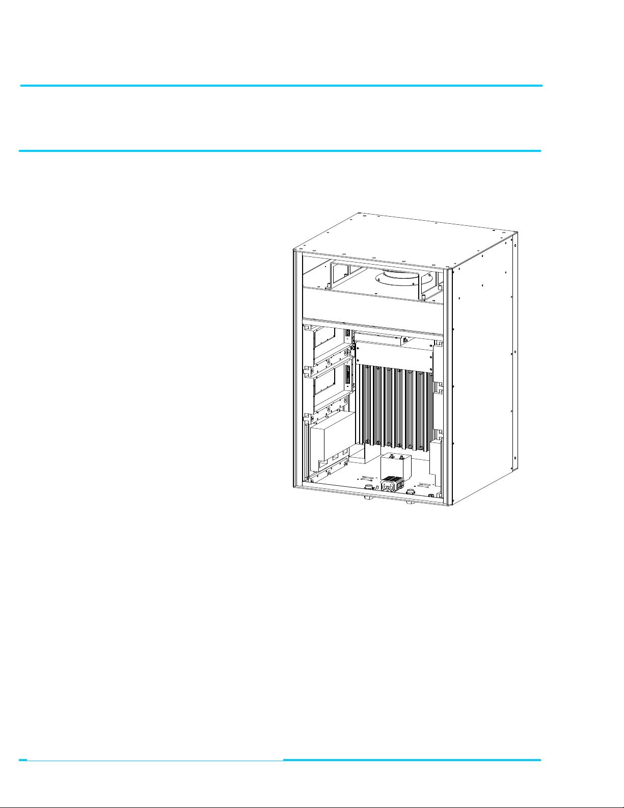
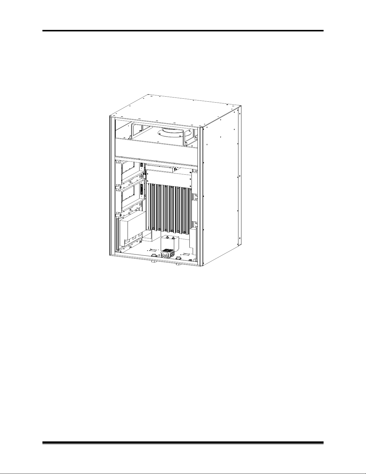
Figure 2-2. Recommended Space
Put updated 3D drawing showing the door, the pedestal, the hanging bracket, and dimensions here.
AMPS EAC-2100 Manual: (Draft, 02/01) Page 2-4
2. Preliminary Decisions
AMPS EAC-2100 Manual: (Draft, 02/01) Page 2-5

2.3.4 Mounting Surface
If the wall hanging bracket is used, make sure that the wall construction and the fastening
hardware is adequate for handling at least the 210 lb (95 kg) of the EAC-2100.
If the pedestal mount is to be used, make sure that the floor or concrete surface is adequate for
handling approximately 60 pounds per square foot (300 kg per square meter). The pedestal has
mounting holes to allow it to be bolted to the floor. Bolting to a surface should be done before
the EAC-2100 is placed on the pedestal.
The EAC-2100 may be mounted either indoors or outside. If it is mounted outside, adequate
drainage away from the pad should be provided to prevent water from accumulatin g underneath
the cabinet.
2.4 Antennas
The EAC-2100 requires four antennas:
D1 antenna: Primary antenna facing donor cell site(s), used for:
• Reception of DCCH and DTC channel signals from donor cell site(s).
• Transmission of DCCH and DTC signals back to cell site(s).
M1 antenna: Primary antenna facing subscribers in the booster coverage area, used for:
• Transmission of boosted DCCH channel and boosted DTC channels to subscribers.
• Diversity reception from subscribers.
• Transmission of hand-back messages to subscribers.
M2 antenna: Second antenna facing subscribers in the booster coverage area, used for:
• Sending hand-in and grab-back messages to subscribers.
• Diversity reception from subscribers.
• Sending data messages to multi-hop EAC-2100s and Multi-Donor Units.
Data mobile antenna (optional): Antenna for the installed cellular mobile. Used for:
• Receiving and transmitting signals from any cell site in the system.
• In many cases the internal data mobile may be connected to the test port on the donor duplexer. This
will allow the data mobile to share the donor antenna for its link back to the donor base station.
Ensure that the proper antenna type and placement have been selected for each antenna.
2. Preliminary Decisions
AMPS EAC-2100 Manual: (Draft, 02/01) Page 2-6

2.4.1 Type
The antennas for the booster area should be chosen by the same criteria as used for a cell site. A
typical installation might use the following antennas:
D1: One high-gain directional antenna pointed toward the donor cell.
M1 and M2: Two identical directional or omnidirectional antennas.
F NOTE: Regardless of the type of antenna chosen, the M1 and M2 antennas must have
Mobile: A low-gain or YAGI base station antenna. Alternatively, a coupler port on the donor
duplexer may be used to share the data mobile with the donor antenna.
2. Preliminary Decisions
identical gain and patterns, and be installed to cover the same area.
AMPS EAC-2100 Manual: (Draft, 02/01) Page 2-7

2. Preliminary Decisions
2100 not adjacent to the donor
70 dBm (at the D1 antenna
2100 in the chain. Each booster
along the path must be able to communicate only with the previous
and next booster. They are not required to be able to receive from or
2.4.2 Placement
Requirements. Antenna locations must meet the following requirements for minimum signal
level, physical separation, and isolation.
• Minimum Signal Level: The minimum signal level from any cell to be used as a donor
must be -75 dBm at the D1 antenna connector on the EAC-2100. The minimum signal level
from the donor cell must be at least -100 dBm at the data mobile antenna feed.
Multi-hop configurations: An EACrequires a forward signal level of at least connector) from the previous EAC-
transmit back to the donor cell site.
• Physical Separation: For diversity operation, the M1 and M2 antennas should be
physically separated by at least 10 feet (3 m) horizontally or 3 feet (1 m) vertically.
F NOTE: Even if diversity reception is not required, both the M1 and M2 antennas
must be installed, since both antennas are used to transmit to the boosted
subscribers.
AMPS EAC-2100 Manual: (Draft, 02/01) Page 2-8
 Loading...