

Andrew Wireless Innovations Group MRx41 User Manual
User’s manual for channel selective repeater MRx41
User’s manual
for
channel selective repeater
MRx41
M0090a0a.doc Id.-No. 148092 Page 1 29-Mar-00

User’s manual for channel selective repeater MRx41
Copyright MIKOM, Buchdorf 2000
All rights reserved.
No parts of this publication may be
reproduced, stored in a retrieval system, transmitted in any form or by
any means, electronical, mechanical photocopying,
recording or otherwise, without prior written permission of the
publisher.
M0090a0a.doc Id.-No. 148092 Page 2 29-Mar-00

User’s manual for channel selective repeater MRx41
Table of Contents
LIST OF FIGURES 7
LIST OF UNIT SPECIFIC ABBREVIATIONS 3
CONTENTS OF DELIVERY 9
HEALTH AND SAFETY WARNINGS 10
PREAMBLE 11
1 INTRODUCTION 13
1.1 Intended purpose 13
1.2 About the MRx41 13
2 FUNCTIONAL DESCRIPTION 14
2.1 Channel modules 18
2.2 Termination module 19
2.3 Mother board 20
2.4 Control module SM2009 21
2.5 Duplexer 24
2.6 Combiner 24
2.7 Measuring aids 24
2.8 Power supply 24
3 FUNCTIONS AND FEATURES 26
3.1 Channel selectivity 26
3.2 DL output power feature 26
3.3 ALC 28
M0090a0a.doc Id.-No. 148092 Page 3 29-Mar-00

User’s manual for channel selective repeater MRx41
3.4 BITE and alarms 28
3.4.1 Handling of alarms 30
3.4.2 Status report 31
3.4.3 Severity levels 31
4 OPTIONAL EQUIPMENT 32
4.1 Remote control via line modem or wireless modem 32
4.1.1 PSTN modem 33
4.1.2 Siemens M1 for GSM900, wireless modem kit 34
4.1.3 Motorola modem for GSM1800, wireless modem kit 34
4.1.4 Nokia modem for PCS1900, wireless modem kit 34
4.2 Battery backup module for modem and control module 37
4.3 LED kit 38
4.4 VSWR module 39
4.5 Traffic statistic module 39
4.6 ICE module 41
4.7 RSSI module 43
4.8 External alarms ( for control module Rev. 07 and higher ) 44
5 INSTALLATION 46
Mechanical specification 46
5.2 Environment and safety 46
5.3 Mechanical installation 47
5.3.1 Wall mounting procedure 48
5.3.2 Pole mounting procedure 49
5.4 Electrical installation 51
5.4.1 Grounding 51
5.4.2 Connection of the antenna cables 52
5.4.3 Power connection 52
M0090a0a.doc Id.-No. 148092 Page 4 29-Mar-00

User’s manual for channel selective repeater MRx41
6 SETTING TO WORK 53
6.1 Preparation 53
6.2 Setting of operational parameters 54
6.2.1 Manual settings by means of rotary switches 54
6.2.2 Local settings via personal computer as terminal 56
6.2.3 Remote control via modem 57
7 TROUBLE SHOOTING 58
7.1 Error indication 58
7.2 Boot process 59
7.3 Alarm monitoring with the alarm history 59
7.4 Power supply 59
7.5 General remarks 60
8 MAINTENANCE 61
8.1 General 61
8.2 Replacement of the power supply and mains fuses 62
8.3 Replacement of the mains cable 63
8.4 Replacement of the RAM / RTC battery 64
8.5 Replacement of the battery backup module ( option ) 65
8.6 Duplexer 66
8.7 PSTN modem kit ( option ) 67
8.8 Channel modules 68
8.9 ICE module 69
8.10 Connecting board 69
M0090a0a.doc Id.-No. 148092 Page 5 29-Mar-00

User’s manual for channel selective repeater MRx41
9 SPARE PARTS LIST 70
9.1 Spare parts for MR341 70
9.2 Spare parts for MR441 72
9.3 Spare parts for MR741 74
10 CONFIGURATION LIST 76
11 APPENDIX 77
11.1 Electrical specifications MR341 77
11.2 Electrical specifications MR441 79
11.3 Electrical specifications MR741 81
11.4 Options for MRx41 83
12 INSTALLATION 84
12.1 Drawing of the repeater 84
12.2 Layout of the repeater ( heat sink ) 85
12.3 Layout of the repeater ( lid ) 86
12.4 ARFCN / Frequency tables for MR341, MR441 and MR741 87
M0090a0a.doc Id.-No. 148092 Page 6 29-Mar-00

User’s manual for channel selective repeater MRx41
LIST OF FIGURES
figure 2-1 One channel system 14
figure 2-2 Configuration of a two channel system 15
figure 2-3 Main unit with connected extension unit 16
figure 2-4 Configuration of a 4 channel system 16
figure 2-5 Configuration of a 6 channel system 17
figure 2-6 Configuration of an 8 channel system 17
figure 2-7 Top view of basic / extension module 18
figure 2-8 Mounting drawing of the termination module 19
figure 2-9 Top view of the mother board 20
figure 2-10 Topview of control module 22
figure 2-11 DIP-Switch settings 23
figure 2-12 Mounting position of the power supply 25
figure 3-1 Channel selectivity 26
figure 3-2 Measuring range 27
figure 4-1 Mounting position of PSTN modem kit 33
figure 4-2 Connection of control module and PSTN modem 34
figure 4-3 Mounting position of PSTN- and wireless modem 35
figure 4-4 Connection of the antenna cable 35
figure 4-5 Battery backup module 37
figure 4-6 LED kit 38
figure 4-7 Cable length and antenna spacing 41
figure 4-8 Configuration of the clamps 44
figure 5-1 System description 46
figure 5-2 Clearance distance 47
figure 5-3 Wall mount procedure 48
figure 5-4 Distances between main unit and extension units 49
figure 5-5 Pole mounting kit 50
figure 5-6 Grounding bolt 51
figure 6-1 Channel rotary switches and gain setting 55
figure 8-1 Mounting position of the power supply and mains fuses 62
figure 8-2 Cable gland 63
figure 8-3 Position of RAM/RTC battery 64
figure 8-4 Battery backup module 65
figure 8-5 PSTN modem kit 67
figure 8-6 Position of hex coded rotary switches 68
figure 8-7 Connecting board 69
figure 12-1 Installation drawing 84
figure 12-2 Layout of the repeater heat sink 85
figure 12-3 Layout of the repeater 86
LIST OF TABLES
table 1-1 List of international sales offices....................................................................................... 12
table 3-1 List of all available alarms ................................................................................................. 29
table 4-1 List of AT commands......................................................................................................... 32
table 6-1 LED indication................................................................................................................... 53
table 8-1 Configuration of hex-coded rotary switches....................................................................... 68
M0090a0a.doc Id.-No. 148092 Page 7 29-Mar-00

User’s manual for channel selective repeater MRx41
LIST OF UNIT SPECIFIC ABBREVIATIONS
ALC Automatic Level Control
ARFCN Absolute Radio Frequency Channel Number
BCCH Broadcast Control Channel
BITE Built In Test Equipment
BTS Base Transceiver Station
DL Downlink
ETS European Telecommunication Standard
ICE Interference Cancellation Equipment
Id.-No. MIKOM part number
I²C-Bus Inter Integrated Circuit Bus ( Philips )
LMT Local Maintenance Timeout
O.C. Open Collector
OMC Operation and Maintenance Centre
NiCd Nickel Cadmium
MR Mikom repeater
MS Mobile Station
Rev . Revision
REPxxxxV1.xx RF repeater software xxxx version 1.xx , e.g. REP1012 V1.04
RF Radio Frequency
RSSI Receive Signal Strength Indication
RTC Real Time Clock
SDA Serial Data Line of I²C-Bus
SCL Serial Clock Line of I²C-Bus
UL Uplink
UPS Uninterruptible Power Supply
VCC Repeater internal DC voltage ( + 5V ) for logic devices
M0090a0a.doc Id.-No. 148092 Page 8 29-Mar-00

User’s manual for channel selective repeater MRx41
CONTENTS OF DELIVERY
Qty1 Repeater MRx41
Qty1 User’s manual for channel selective repeater MRx41
Qty 1 Software manual for REP1012V1.xx
Qty1 Set of test protocols consisting of an electrical acceptance test protocol
and a safety test protocol applying to the power supply
Qty1 Spare parts kit containing:
- 1 control cable RS232, DB9 female / DB9 female, 3m
- 3 socket head cap screws M3.0 x 30
- 2 tallow-drop screws M5.0 x 25
- 2 tallow-drop screws M2.0 x 6
- 2 tallow-drop screws M3.0 x 5
- 4 straight pins 3.0 x 25
- 2 fuses 2.0 A
- 2 O-ring 4 x 2 mm
- 2 Tyraps
- Silicon heat conducting paste
- 4 special nuts M4
- 1 O-ring 63 x 2 mm
- 1 fuse 10 A ( F )
Tools
- 1 hex socket key, size 2.5
- 1 Torx key
- 1 hex socket screw key , size 4, long
Qty1 Wall mounting sheet
M0090a0a.doc Id.-No. 148092 Page 9 29-Mar-00

User’s manual for channel selective repeater MRx41
The grounding of the unit has to be performed by all means. A
HEALTH AND SAFETY WARNINGS
F Note:
F Note:
F Note:
F Note:
The electrical installation has to be performed in accordance with the
safety regulations of the local authorities. Due to safety reasons the
electrical installation must be performed by qualified personnel. The
cover of this unit should not be opened while power is applied.
Subsequent installation, commissioning and maintenance activities
that require the unit to be powered with the cover open shall only be
carried out by suitably qualified personnel.
grounding bolt is provided at the outside of the cabinet in order to
connect the earth bonding cable.
Make sure that a suitable mounting surface is used. Only adequate
manpower is allowed to handle the system.
ESD precautions have to be observed! Before maintenance work use
the available grounding system to connect ESD protection
measures.
F Note:
F Note:
Due to power dissipation the repeater may heat up the air volume
inside the cabinet and reach a very high temperature. Therefore it is
recommended to mount the repeater in the vertical plane to a wall or
a mast without additional enclosure to provide sufficient ventilation.
Between the housing and the wall a minimum distance must be kept
in order to provide air circulation.
Close the repeater housing only after a thorough control of the cable
layout, in order to avoid any damage of the cables.
M0090a0a.doc Id.-No. 148092 Page 10 29-Mar-00

User’s manual for channel selective repeater MRx41
PREAMBLE
Repeaters are an essential part of an efficient and effective wireless system. They
can enhance outdoor coverage as hole fillers, provide coverage extension service on
highways, canyons and in tunnels at the fraction of the cost of a new cell site.
MIKOM is a leading manufacturer of repeaters. They provide excellent electrical
characteristics, they are light-weight and easy to install. Hence, the MIKOM repeater
is the preferred solution.
Your repeater has been built using highly reliable materials. A comprehensive
quality assurance has been applied to all fabrication steps. This secures constant
quality of the product. Every repeater leaves the factory only after a thorough final
acceptance test, accompanied by a test certificate, which warrants perfect function.
The acceptance test protocol is subject of the delivery and it is fixed to the repeater
lid in order to provide a quick reference for the user.
Any intervention has to be performed by authorised persons only. If you need
technical assistance with the repeater MRx41 contact your local sales office ( see
table 1-1 ) or MIKOM directly at following address:
MIKOM GmbH
Industriering 10
86675 Buchdorf
Germany
Tel: +49 (0) 90 99 - 6 90
Fax: +49 (0) 90 99 - 69 31
email: sales@mikom.com
http://www.mikom.com
Under consideration of all references given in this manual, the repeater should be
taken into service without any complications and should operate trouble-free for a
long time.
M0090a0a.doc Id.-No. 148092 Page 11 29-Mar-00

User’s manual for channel selective repeater MRx41
LIST OF INTERNATIONAL SALES OFFICES
Allen Telecom Inc. Allen Telecom Pty Ltd Forem France
30500 Bruce Industrial Parkway 6 Stuart Street Z.I. des Ebisoires
Cleveland, Ohio 44 139-3996 Padstow NSW 2211 78370 Plaisir
USA Australia France
Phone: +1 ( 440 ) 349-8400 Phone: +61 ( 2 ) 9774-4200 Phone: +33 ( 1 )30-79-15-30
FAX: +1 ( 440 ) 349-8407 FAX: +61 ( 2 ) 9774-4500 FAX: +33 ( 1 ) 30-55-55-37
FOREM S.p.A. AT Singapore AT China
Via Archimede N. 22/24 80 Marine Parade Road CITIC Building, # 11-04
20041, Agrate Brianza #19-1 Parkway Parade 19 Jianguomenwai Avenue
Milan Singapore 449269 Beijing
Italy China 100004
Phone: +39 ( 039 )605-41
Phone: +65 ( 345 ) 8022 Phone: +86 ( 10 ) 6508-3088
FAX: +39 ( 039 ) 605-4477 FAX: +65 ( 345 ) 8033 FAX: +86 ( 10 )6508-3066
AT Canada FOREM UK AT Hong Kong
1815 Ironstone Manor, # 12
Pickering, Ontario L1W 3W9
Canada
Unit D
Castle Industrial Park
Pear Tree Lane
Newbury, Berkshire
1603 Remington Center,
23 Hung To road,
Kwun Tong, Kowloon
Hong Kong
U.K. RG 14 2EZ
Phone: +1 ( 905 ) 839-3474 Phone: +44 ( 1635 ) 569-695 Phone: +852 ( 2389 ) 1844
FAX: +1 ( 905 ) 839-4663 FAX: +44 ( 1635 ) 569-463 FAX: +852 ( 2389 ) 4864
AT India
B-256 Ground Floor.
Chittaranjan Park
New Delhi 110019
Phone: +91 ( 11 ) 696-3918
FAX: +91 ( 11 ) 652-1648
MIKOM Switzerland
Tiergartenweg 1
4710 Balzthal
Switzerland
Phone: +41 ( 6238 ) 61260
FAX: +41 ( 6238 ) 61261
MIKOM Austria
Himbergerstr. 7/3/1
2320Schwechat
Austria
Phone: +43 ( 1 ) 706 – 3999
FAX: +43 ( 1 ) 706 – 39999
table 1-1 List of international sales offices
M0090a0a.doc Id.-No. 148092 Page 12 29-Mar-00

User’s manual for channel selective repeater MRx41
1 Introduction
1.1 Intended purpose
Cellular telephone systems transmit signals in two directions between base stations
and mobile telephones within the signal coverage area.
If weak signal transmissions occur within the coverage area because of indoor
applications, topological conditions or distance from the transmitter, a repeater is
used to extend transmission range. In the downlink path the repeater will pickup the
signal from a donor antenna of an existing cell, amplifies and re-transmits it into the
desired dark spot. In the uplink direction the repeater will receive signals from
mobile stations present in its coverage area and re-transmits them to the
corresponding base station.
1.2 About the MRx41
The repeater MRx41 is a channel selective amplifier, which bi-directionally amplifies
signals between mobile stations and a base station in the GSM900, GSM1800 und
PCS1900 mobile telephone system. It can provide highly selective amplification of
up to 8 channels, thus enabling radio coverage in regions where satisfactory quality
of communication is disabled.
MRx41 modules can also be combined with other MRx41 repeater modules in order
to create a combines GSM900, GSM1800 or PCS1900 repeater system. Other
modules, operating in TACS, ETACS and AMPS are available as well. When
different modules are combined, a common antenna terminal and a common control
interface is available. The basic unit is capable of 2 channels and easily expandable
by adding 2-channel extension units delivered in separate cabinets.
The repeater can be set locally or remotely. For modem operation different
interfaces are available. The design of the repeater comprises a large number of
functions which the operator may monitor via terminal emulation program or the
Mikom OMC software platform. An easy to understand and easy to learn
communication language supports the operator to query status reports from the
repeater or to change settings.
F Note: It is not possible to combine MRx41 units / modules with MRx40 units
/ modules.
M0090a0a.doc Id.-No. 148092 Page 13 29-Mar-00
User’s manual for channel selective repeater MRx41
2 Functional description
The repeater MRx41 can be delivered as an one channel system, expandable up to
an 8 channel system by means of extension units connected to the main unit.
The following block diagrams shall illustrate the different configurations.
Configuration of an one channel system
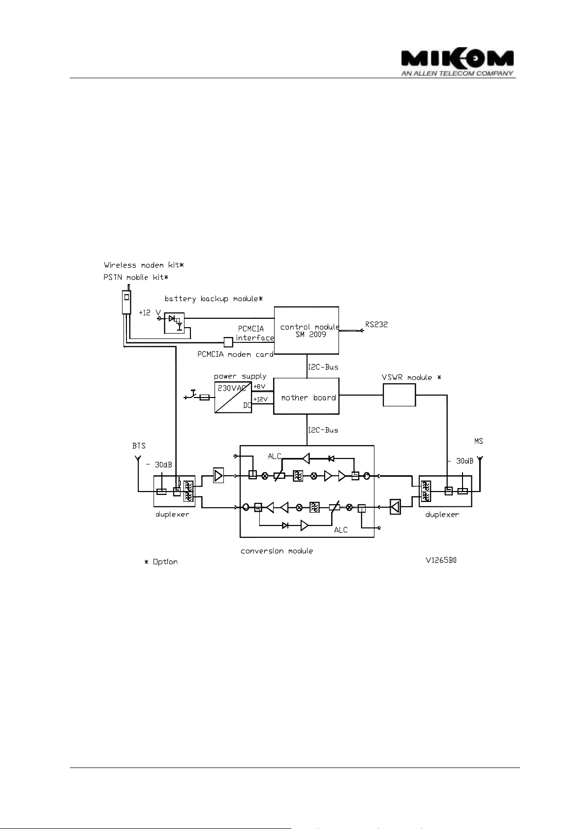
Figure 2-1 illustrates the configuration of an one channel system which consists of
one basic module ( channel 1 ).
figure 2-1 One channel system
M0090a0a.doc Id.-No. 148092 Page 14 29-Mar-00
User’s manual for channel selective repeater MRx41
Configuration of a two channel system
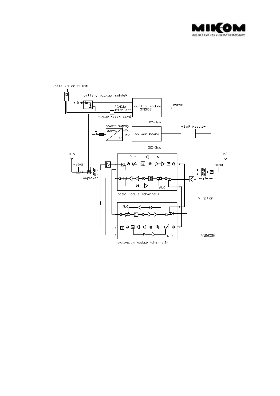
Figure 2-2 illustrates the configuration of a two channel system, containing one
basic module and one extension module.
figure 2-2 Configuration of a two channel system
M0090a0a.doc Id.-No. 148092 Page 15 29-Mar-00
User’s manual for channel selective repeater MRx41
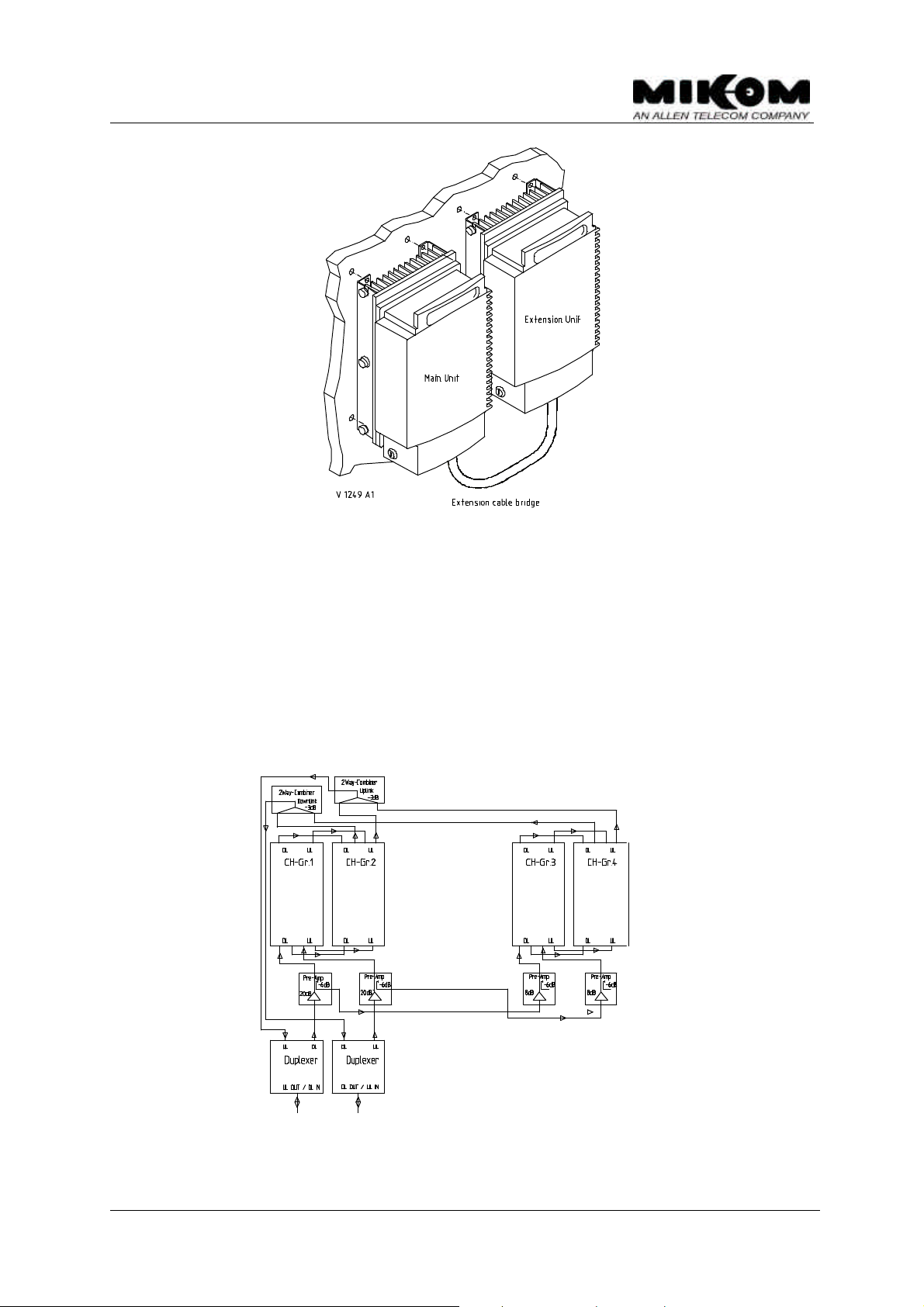
figure 2-3 Main unit with connected extension unit
Configuration of a 4 channel system
Figure 2-3 illustrates the configuration of a 4 channel system. For the configuration
of 3 or 4 channels it is necessary to install a combiner module in the main unit. The
block diagram describes the connection between the channel modules and the
combiner module. The mother board and the control module are not included in the
figure below.
figure 2-4 Configuration of a 4 channel system
M0090a0a.doc Id.-No. 148092 Page 16 29-Mar-00
User’s manual for channel selective repeater MRx41
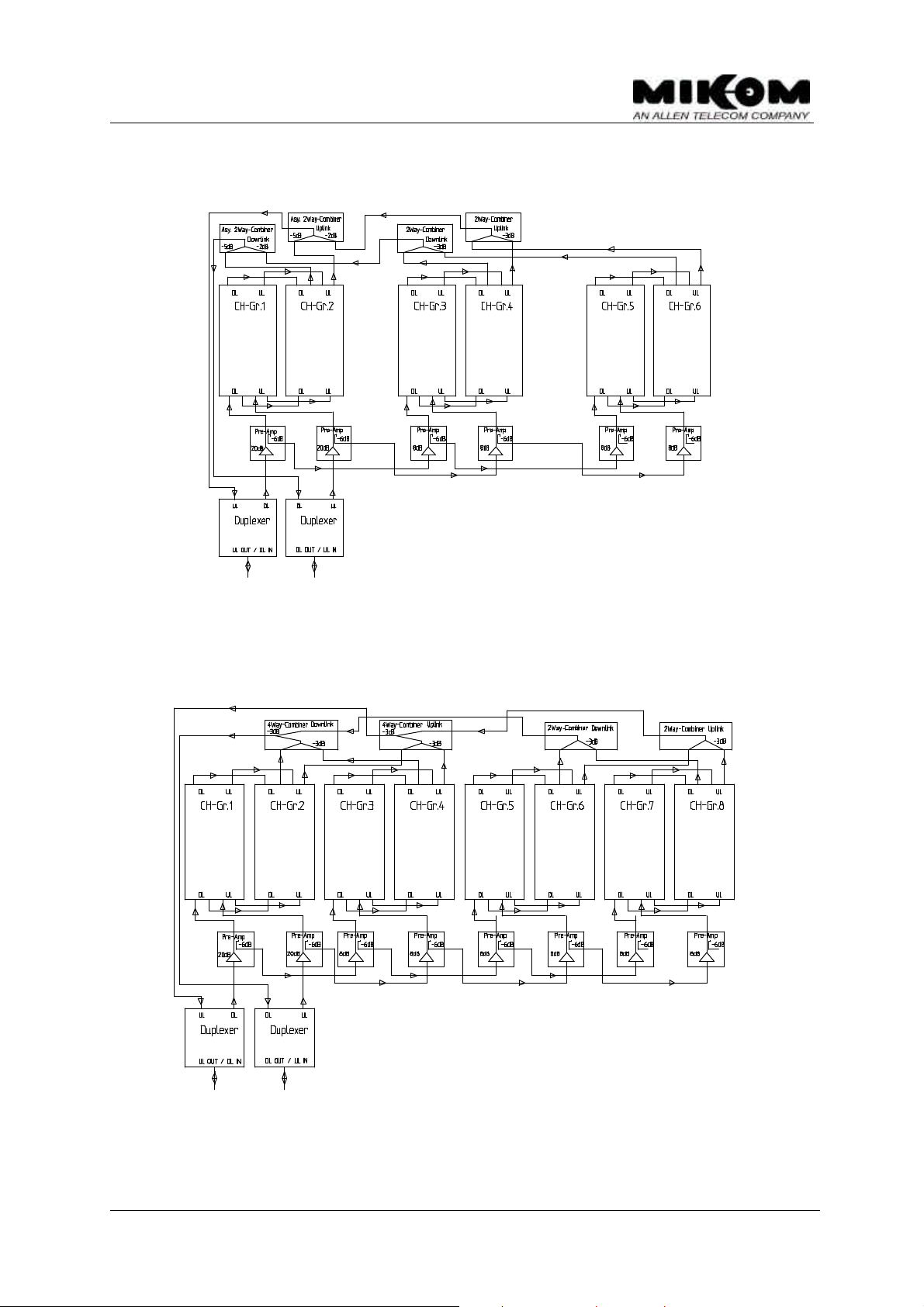
Configuration of a 6 channel system
figure 2-5 Configuration of a 6 channel system
Configuration of an 8 channel system
figure 2-6 Configuration of an 8 channel system
M0090a0a.doc Id.-No. 148092 Page 17 29-Mar-00
User’s manual for channel selective repeater MRx41
2.1 Channel modules
Two different types of conversion modules have been designed.
1. Basic module: Channel 1, 3, 5 and 7
2. Extension module: Channel 2, 4, 6 and 8
Extension
Basic
figure 2-7 Top view of basic / extension module
The repeater consists of two amplifier chains, which are connected antiparallel. The
receive path of one direction is connected to the transmit path of the other direction
by a frequency separation unit, in the following denominated as a duplexer, which
combines both signals to an antenna.
The task of the conversion modules is to amplify the receive signals and to convert
them into an intermediate frequency. The signals, then, proceed a filter stage
comprising of highly selective filters, and run through a digital controllable
attenuator. The attenuation can be set in steps of 2 dB, locally or remotely. By using
the same synthesizer frequency, that was used to convert the signals down to
intermediate frequency, the intermediate frequency is mixed up to the original
frequency.
The synthesizer is controlled via an I²C-Bus. In case of a breakdown in mains, gain
and frequency data are non-volatile stored in an EEPROM on board.
M0090a0a.doc Id.-No. 148092 Page 18 29-Mar-00
User’s manual for channel selective repeater MRx41
The filters of the MRx41 series have the bandwidth of a GSM900; GSM1800 or
PCS1900 channel.
The RF output is protected by limiting the output power with an ALC circuitry inside
the module.
High stability against intermodulation is achieved by isolators before and after the
combiner amplifiers, which inhibits crosstalk into the other amplifier path, thus
preventing the generating of parasitic mixing products. The combiner is followed by
a duplexer.
F Note: For the exchange of a channel module or the installation of a new
channel module, the slave address of the synthesizer has to be
set ( see chapter 8.8).
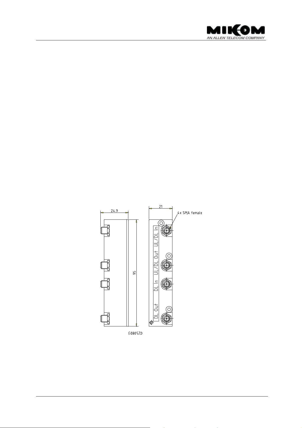
2.2 Termination module
To install a repeater system with an odd channel number ( e.g. 1, 3, 5 or 7 channels
) a termination module has to be installed instead of an extension module. This is
necessary in order to keep the gain balance, otherwise the last channel provides 3
dB more gain and output power.
figure 2-8 Mounting drawing of the termination module
M0090a0a.doc Id.-No. 148092 Page 19 29-Mar-00
User’s manual for channel selective repeater MRx41
Mother board
of repeater unit
ON
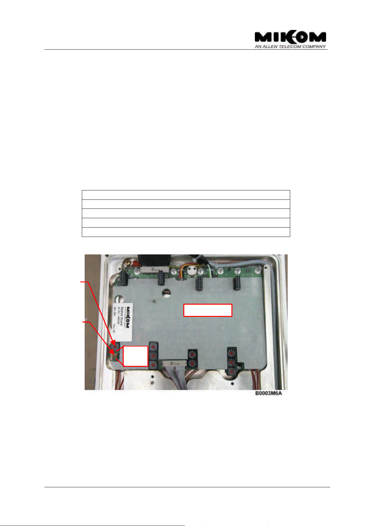
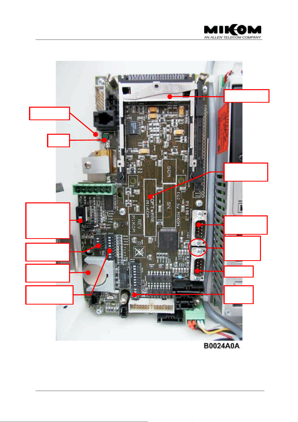
2.3 Mother board
The function of the mother board is the communication between the conversion
modules and the control module via the I²C-Bus but also the support of all necessary
DC voltages and connections. All signals are recognized from the mother board
logic. Furthermore each repeater unit has an allocated address set by means of a
rotary switch. The address of the repeater has been set already in the factory. The
rotary switch is located on the left-hand side of the mother board on top of the board.
F Note: Don’t adjust this switch unless it is necessary.
Configuration of the rotary switch to set the address of the repeater unit.
0 = Main Unit ( channel 1 and 2 )
1 = Extension Unit 1 ( channel 3 and 4 )
2 = Extension Unit 2 ( channel 5 and 6 )
3 = Extension Unit ( channel 7 and 8 )
4...F Do not use!
Rotary switch
to set address
DIP-Switches to
activate the
extension I²C-Bus
OFF
figure 2-9 Top view of the mother board
M0090a0a.doc Id.-No. 148092 Page 20 29-Mar-00

User’s manual for channel selective repeater MRx41
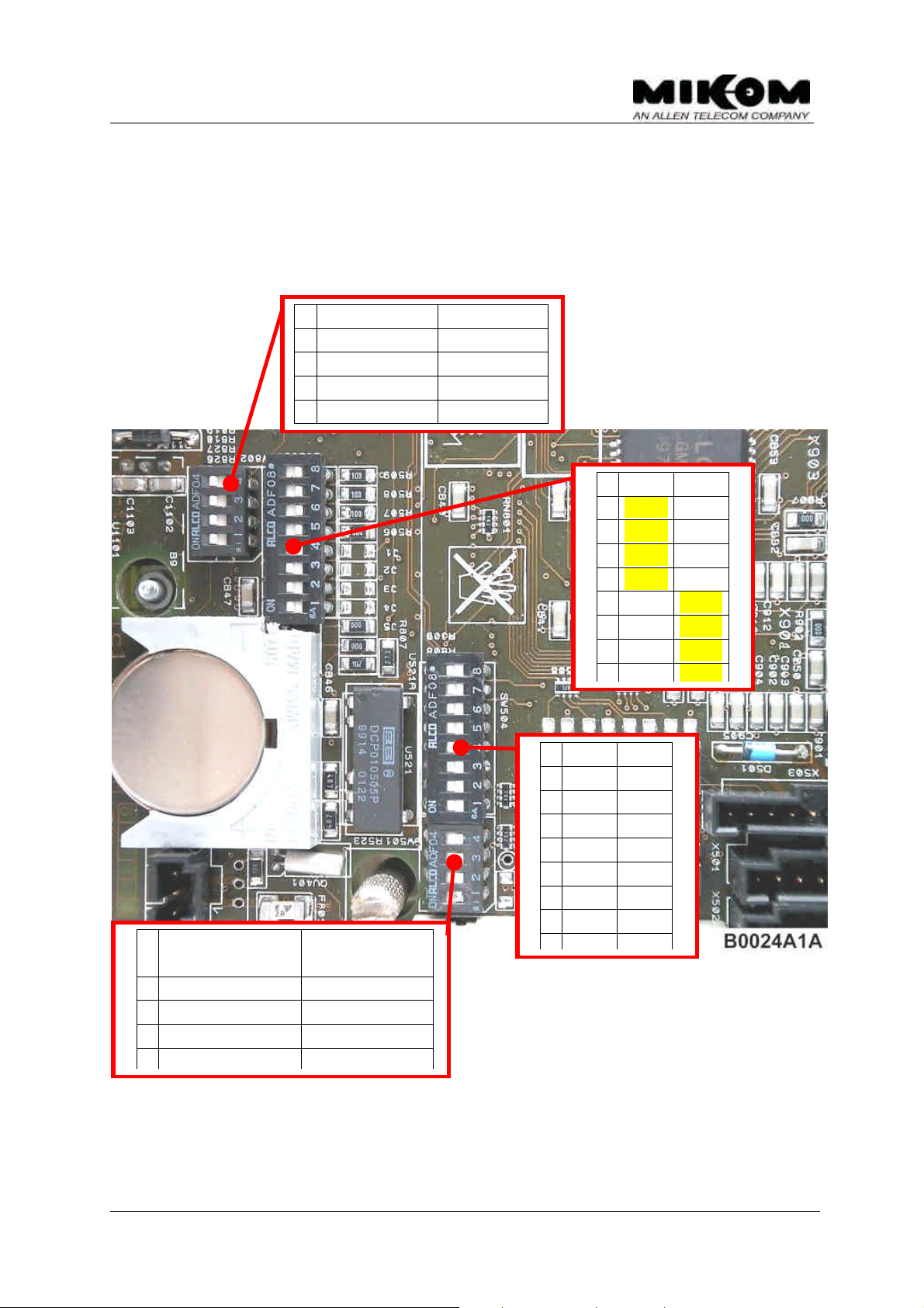
2.4 Control module SM2009
The control module SM2009 is a DOS compatible micro computer. The whole
communication between the operator and the repeater can be done via the control
module. By using either the RS232 interface or the PCMCIA slot and a mobile the
repeater can be controlled locally or remotely by using a VT100 terminal, or a PC
emulating the VT100 terminal.
Gain of uplink and downlink can be controlled, channels can be set and status
messages can be received remotely.
The data transfer between the control module SM2009 and the mother board is
realised by the I²C-Bus.
The I²C-Bus concept was developed by Philips for the serial connection of integrated
circuits within one device. Two wires, SDA - serial data and SCL - serial clock, carry
information between the devices connected to the bus. The MRx41 I²C-Bus concept
is working with a bit rate of 1.5 kbit/s. All configuration parameters are stored nonvolatile in an EEPROM on the control module, so that in case of a power supply
failure all user settings can be restored completely.
M0090a0a.doc Id.-No. 148092 Page 21 29-Mar-00
User’s manual for channel selective repeater MRx41
RS 232
DIP Switch
information
not in use
L1 & L2
L3
PCMCIA slot
(3) Software
BBU switch
ON: No BBU
OFF: BBU in
use
(1) PSTN /
RAM/RTC
(2) MR / MOR
RS 232
Solder
bridge in
Mode
figure 2-10 Topview of control module
(See comments at following page)
M0090a0a.doc Id.-No. 148092 Page 22 29-Mar-00
User’s manual for channel selective repeater MRx41
MR
MOR
1
manual auto
(1) External alarms or PSTN modem selection by DIP-Switches
(2) Configuration DIP-Switches for MR or MOR (Master Unit) repeater
(3) Fixed location for labels (control module Id.- No., revision stage, repeater
software, serial number)
ON OFF
Ext. Alarm 1 PSTN (a)
4
Ext. Alarm 2 PSTN (b)
3
Ext. Alarm 3 PSTN (c)
2
Ext. Alarm 4 PSTN (d)
1
ON OFF
MOR MR
8
MOR MR
7
MOR MR
6
MOR MR
5
MR MOR
4
MR MOR
3
MR MOR
2
ON OFF(default
values)
DO NOT USE! auto
4
3
2
n.c. n.c.
remote mode local mode
figure 2-11 DIP-Switch settings
ON OFF
VCC O.C.
8
VCC O.C.
7
VCC O.C.
6
VCC O.C.
5
VCC O.C.
4
VCC O.C.
3
VCC O.C.
2
M0090a0a.doc Id.-No. 148092 Page 23 29-Mar-00

User’s manual for channel selective repeater MRx41
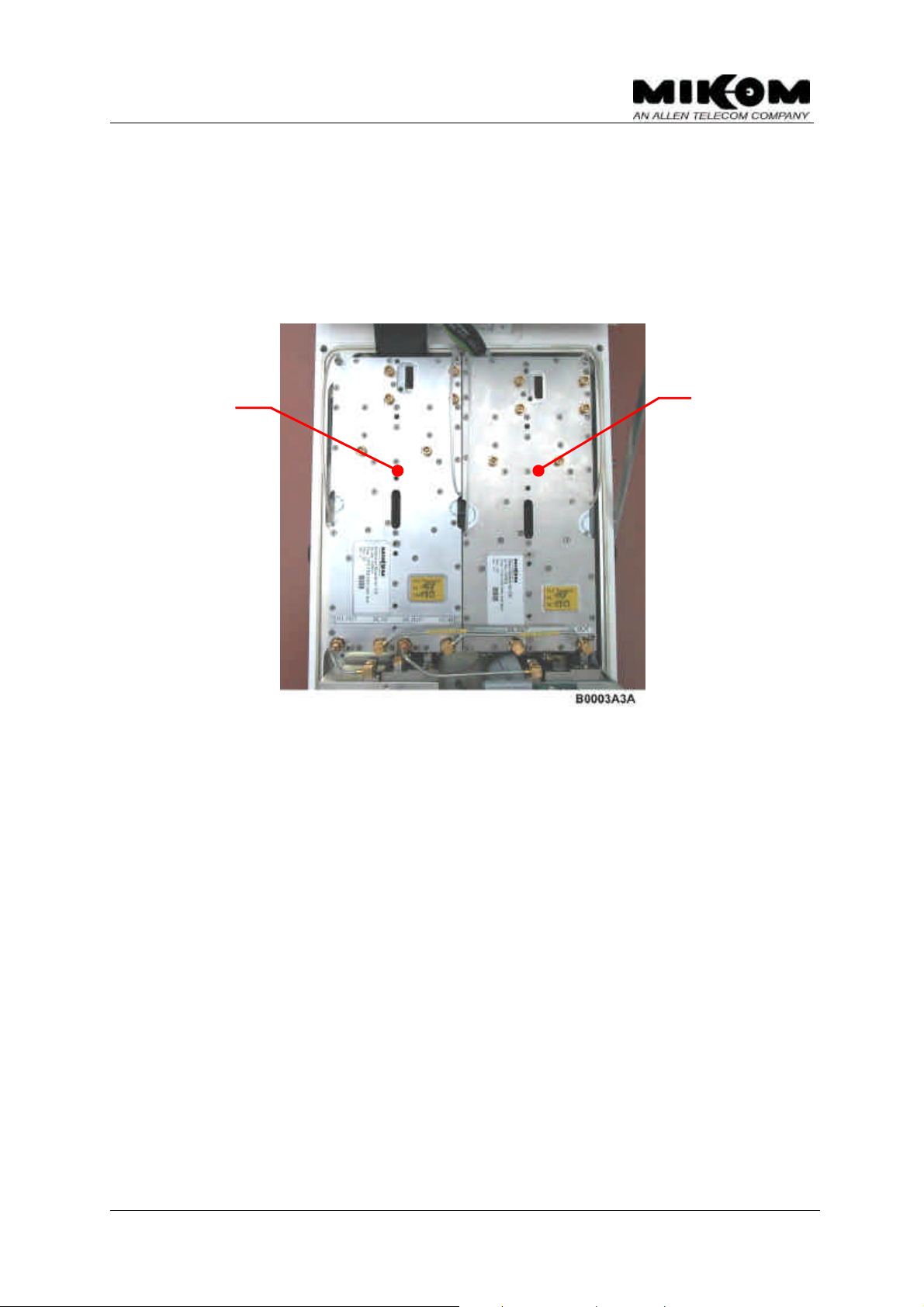
2.5 Duplexer
The receive path of one direction is connected to the transmit path of the other
direction by a frequency separation unit, in the following denominated as a duplexer,
which combines both signals to an antenna.
The task of the duplexer ( see figure 12-2 Layout of the repeater heat sink ) is to
isolate uplink from downlink, i.e. isolate transmit path from receive path. The pass
bandwidth of the duplexer is the required width of the uplink band and the downlink
band respectively in the GSM1800 and PCS1900 band.
2.6 Combiner
After passing through the final stage the signals of all channel groups will be
combined from the combiner module in the UL and in the DL path. The combiner is
only equipped from 3 channels up to 8 channels.and will be followed by the
duplexer. A combiner is not required in an one or two channel repeater.
2.7 Measuring aids
With the built-in RF probe signals can be applied or detected. The probes provide a
coupling factor of 30 dB. This facilitates measurements under all operational
conditions, while an antenna or a dummy load may be connected. Each duplexer is
equipped with one coupler.
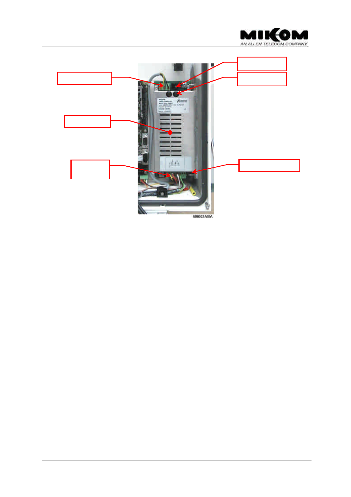
2.8 Power supply
The power supply is provided by 230 Vac (optionally 115 Vac or 48 Vdc or 24 Vdc)
mains power. The following figure shows the mounting position of the power supply
in the repeater lid. The secondary voltage is + 8 Vdc for the channel modules and
the mother board logic, + 12 Vdc for the control module.The power supply can be
switched on or off by means of an external switch. The modules of the repeater are
voltage free if the power supply is switched off.
F Note: To switch the whole repeater voltage free, you have to disconnect
the power lead from mains.
The power supply is factory-set ( with load ) to the following voltages and must not
be changed:
• 7.8 V ± 0.1 V
• 12.4 V ± 0.1 V
M0090a0a.doc Id.-No. 148092 Page 24 29-Mar-00
User’s manual for channel selective repeater MRx41
Power supply
connector
Mains switch
Mains connector
DC voltage
figure 2-12 Mounting position of the power supply
Mains fuses
Secondary 10 A fuse
M0090a0a.doc Id.-No. 148092 Page 25 29-Mar-00
User’s manual for channel selective repeater MRx41
3 Functions and features
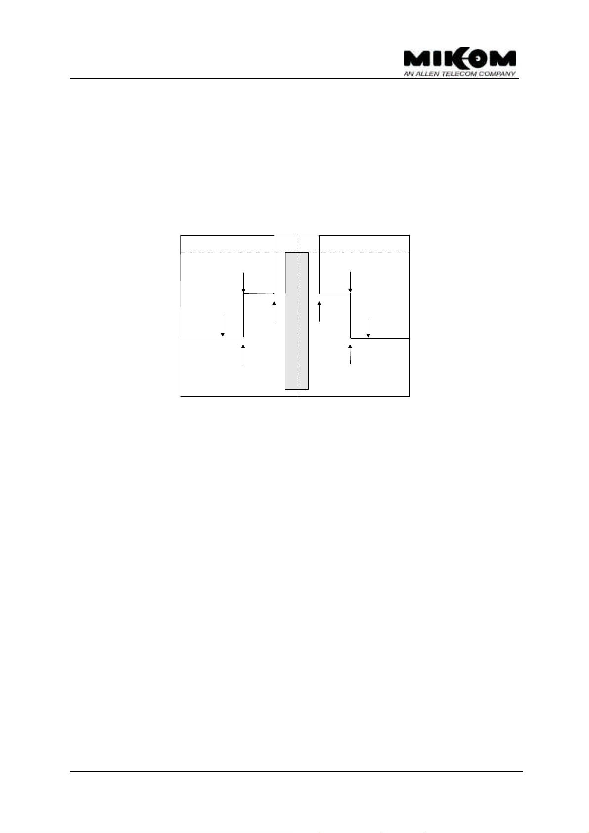
3.1 Channel selectivity
The selectivity of the conversion modules is achieved by highly selective filters,
designed to meet the requirements of a 200 kHz channel and is necessary in order
not to amplify adjacent channels.
Nominal enhancer gain
- 3 dB enhancer gain
- 35 dB
- 35 dB
- 60 dB
-600kHz
-400kHz
-100kHz
F
+400kHz
+100kHz
C
- 60 dB
+600kHz
figure 3-1 Channel selectivity
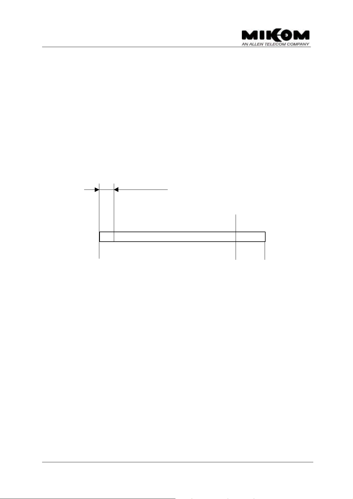
3.2 DL output power
This feature measures the output power in the DL output path of the repeater. If the
output power falls below a certain level an alarm can be released. The power level
and the mask for the alarm can be set by the customer.
The feature shows the provider the output power of the repeater and thus an
optimum of output power can be achieved.
The alarm can be forwarded to an OMC, so that faults and irregularities can be
recognised and eliminated rather quick.
M0090a0a.doc Id.-No. 148092 Page 26 29-Mar-00
User’s manual for channel selective repeater MRx41
< 20 dBm > +33 dBm
ALC alarm
Technical data:
Measuring range ( see figure 3-2 )+ 20 dBm to max. output power (+ 33 dBm)
in steps of 2 dB from + 20 dBm to + 30 dBm
and in steps of 1 dB from + 30 dBm to max.
output power (+ 33 dBm)
Alarm threshold can be set in the measuring range
Requirements:
The power output option can be implemented in each MIKOM repeater provided the
repeater operates channel selective in the DL.
P
alarm threshold
out
Resolution:
P
low alarm
out
2 dBm ± 1 dBm
±
+ 20 dBm + 30 dBm + 33 dBm
Displayed range
figure 3-2 Measuring range
M0090a0a.doc Id.-No. 148092 Page 27 29-Mar-00

User’s manual for channel selective repeater MRx41
3.3 ALC
In order to protect the amplifiers from overload and to prevent the system to
generate spurious emission, the amplifiers have an Automatic Level Control,
designed to limit the output power to a constant value ( max. output power ). A part
of the output power is decoupled, rectified, amplified and used to control an
attenuator network in the conversion modules. In order to avoid oscillation, the
control amplifier has an integrating characteristic.
The threshold for the ALC can be set manually for each motherboard. The ALC
settings affect both modules on the motherboard for UL and DL separately. The ALC
threshold will be set in the factory and can be found on the test data sheet of the
repeater In case a new module will be mounted or a module will be exchanged the
values for the ALC threshold in each link have to be compared. In case they are
different the higher value has to be set. An increase of the input signal results in an
increase of the output signal. If the output power exceeds the required power, an
ALC alarm is triggered.
3.4 BITE and alarms
The Built-In TEst concept comprises the monitoring of the power supplies, the
operational currents in the conversion modules, the mother board and the remote
control interface. Furthermore the temperature of the repeater is monitored.
There are three multicoloured LEDs mounted on the control module. The LED L3
indicates the presence of +12 Vdc in the repeater. Every alarm is indicated by failure
LEDs, L1 and L2 together ( simultaneously ), mounted on the control module ( see
chapter 2.4 ).
In case a hardware failure is detected the concerning hardware module has to be
replaced. If all alarms have been acknowledged the summary error LEDs are set
back from red to green indication.
F Note: In case of mains power failure all data of the alarm history list are
lost.
In case, a remote alarm should be required, a potential free relay contact can be
used, which is situated on the connecting board.
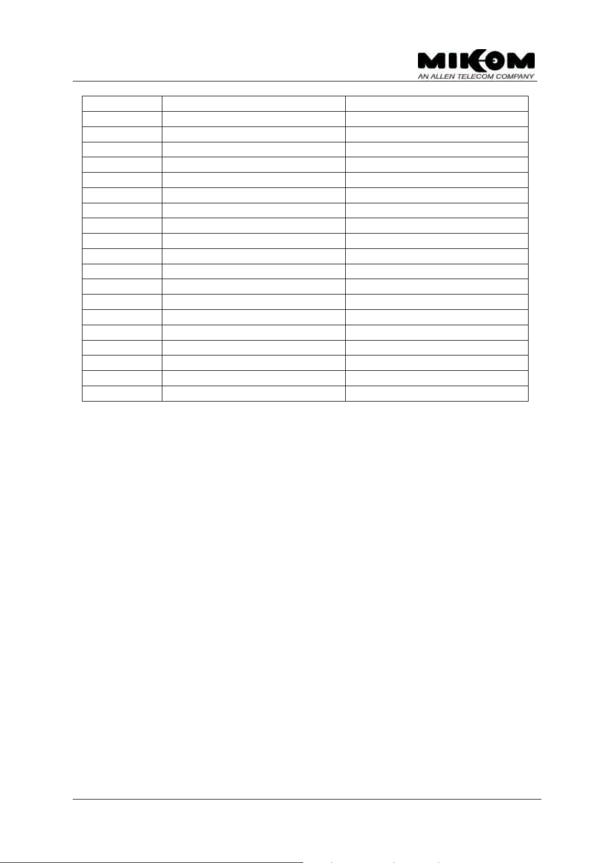
The following list comprises all available alarms in the repeater. These alarms may
occur in the alarm history list.
NO. ALARM NAME ALARM ACTIVE STATUS
1 AMPLIFIER BIAS FAILURE
M0090a0a.doc Id.-No. 148092 Page 28 29-Mar-00
User’s manual for channel selective repeater MRx41
2 POWER SUPPLY 8 V FAILURE
3 POWER SUPPLY 12 V FAILURE
4 POWER SUPPLY MAINS FAILURE
5 SYNTH FAILURE
6 DOOR OPEN
7 VSWR** ALARM
8 ALC FAILURE
10 ACCU VOLTAGE** LOW
11 LITHIUM BATTERY VOLTAGE LOW
12 OVERTEMP
13 PWROUT LOW
13 RSSI** LOW
14 INVALID LOGIN ATTEMPT
15 I2C FAILURE
16 OSCILLATION** ALARM
17 GAIN REDUCTION** WARNING
18* EXT. ALARM 1** FAILURE
19* EXT. ALARM 2** FAILURE
20* EXT. ALARM 3** FAILURE
21* EXT. ALARM 4** FAILURE
* Alarm default settings are changeable by software.
** Only available if option is activated by factory.
table 3-1 List of all available alarms
M0090a0a.doc Id.-No. 148092 Page 29 29-Mar-00

User’s manual for channel selective repeater MRx41
3.4.1 Handling of alarms
As soon as the software recognises a valid alarm, a message can be transmitted to
the OMC.
If the repeater is operating in modem mode the alarm message ‘MIKOM>
REPEATER REQUIRES OPERATOR ATTENTION’ will be sent via modem to the
terminal or the OMC. The first of two stored telephone numbers will be dialled. In
case a connection cannot be established the second telephone number will be
dialled. If this should be unsuccessful as well, the call will be repeated after a preset delay. Default setting is 10 minutes. The repetition cycle can be set by software.
The alarm check routine is searching every 10 seconds for alarms ( polling
principal ). To decide whether an alarm is a valid alarm it must remain for 5 polling
cycles, only then it will be recognized and entered in the alarm history. As soon as
the alarm is valid the contacts of the alarm relay at the mother board are set.
Additionally two summary error LEDs are set to red light to indicate an alarm. These
LEDs are mounted on the control module ( see figure 12-3 ).
The entry in the alarm history describes the alarm type, the time and the date when
it occurred. It is not possible to locate the defect module, only the reason.
Entered alarms in the alarm list can be acknowledged by simply ringing back and
typing a software command. It is also possible to acknowledge alarms in local
mode. Acknowledged alarms will be indicated with ‘-ACK’. As soon as the alarms
have been acknowledged the alarm relay will be reset and the summary LEDs
switch back to green light again.
If the same alarm cause occurs again, it will be entered in the alarm list ( not
acknowledged ) after 5 polling cycles. An already acknowledged alarm must have
an interruption of at least 5 polling cycles to be detected by the software as a new
alarm. Only then the alarm will be entered again in the alarm history ( not
acknowledged ). There exists no command to delete the alarm history.
The alarm list has a capacity of about 50 alarm entries. If more alarms occur the
oldest message will be deleted first ( FIFO principle ).
In the software exists no alarm clear message, i.e., the repeater sends no message
to the terminal or the OMC if an alarm has disappeared by itself.
M0090a0a.doc Id.-No. 148092 Page 30 29-Mar-00
 Loading...