


User’s manual for Repeater MR801B Power
User’s manual for
band or channel selective Repeater
MR801B Power
(Id.-No. 148613)
Author: Approved: QA:
M0067A0A.doc Id.-No 151111 Page 1 02-JUNE-99

User’s manual for Repeater MR801B Power
Table of Contents
LIST OF UNIT SPECIFIC ABBREVIATIONS 6
CONTENTS OF DELIVERY 9
HEALTH AND SAFETY WARNING 10
PREAMBLE 11
1 INTRODUCTION 13
1.1 Intended purpose 13
1.2 About the MR801B POWER 13
2 FUNCTIONAL DESCRIPTION 14
2.1 General 15
2.2 RF modules 15
2.3 Mother board 17
2.4 Control module SM 2009 18
2.5 Duplexer 19
2.6 Active combiner 20
2.7 Measuring aids 20
2.8 Power supply 21
2.9 Feed forward amplifier 22
3 FUNCTIONS AND FEATURES 23
3.1 Band and channel selectivity 23
3.2 Gain setting 23
3.3 ALC 24
M0067A0A.doc Id.-No 151111 Page 2 02-JUNE-99

User’s manual for Repeater MR801B Power
3.4 BITE and alarms 24
3.4.1 Handling of alarms 26
3.4.2 Status report 27
3.4.3 Severity levels 28
4 OPTIONAL EQUIPMENT 30
4.1 VSWR module 30
4.2 External alarms 30
4.3 Modem 32
4.4 Battery backup module 32
5 SPECIFICATION 34
5.1 Electrical specification 34
5.2 Mechanical specification 36
5.3 Environmental and safety 36
5.4 External electrical interfaces 36
5.4.1 Electrical power 36
5.4.2 RF connections 37
5.5 External RF output 39
6 INSTALLATION 40
6.1 Mechanical installation 41
6.2 Electrical installation 44
6.2.1 Grounding 44
6.2.2 Power connection 45
6.2.3 Connection of the antenna cables 45
7 SETTING TO WORK 46
7.1 Preparation 46
7.2 Setting of operational parameters 47
7.2.1 Manual settings by means of rotary switches 47
7.2.2 Settings via personal computer as terminal 49
7.2.3 Settings via modem 52
M0067A0A.doc Id.-No 151111 Page 3 02-JUNE-99

User’s manual for Repeater MR801B Power
8 TROUBLE SHOOTING 53
8.1 Error indication 53
8.2 Boot process 53
8.3 Alarm monitoring with the STATUS HIST command 54
8.4 Power supply 54
8.5 General remarks 54
9 MAINTENANCE 55
9.1 General 55
9.2 Replacement of the fuses (mains) 55
9.3 Replacement of the power supply fuse 56
9.4 Replacement of the mains cable 56
9.5 Replacement of the RAM / RTC battery 57
9.6 Replacement of the dummy battery backup module 58
9.7 Replacement of duplexers 59
9.8 Replacement of RF modules 60
9.9 Replacement of the control module SM 2009 62
9.10 Replacement of power supplies 63
9.11 Replacement of active combiner modules 64
9.12 Replacement of feed forward amplifiers 65
M0067A0A.doc Id.-No 151111 Page 4 02-JUNE-99

User’s manual for Repeater MR801B Power
10 SPARE PARTS LIST 68
11 APPENDIX 70
11.1 Installation drawing of the Repeater 70
11.2 Top view of the Repeater (left side , one channel configuration) 71
11.3 Top view of the Repeater (right side, one channel configuration) 72
11.4 One channel configuration – cabling and block diagram 73
12 INDEX 75
M0067A0A.doc Id.-No 151111 Page 5 02-JUNE-99

User’s manual for Repeater MR801B Power
LIST OF FIGURES AND TABLES
table 1-1 List of international sales offices ............................................................................12
figure 2-1 Block diagram of MR801B Power .......................................................................14
figure 2-2 Top view of an RF module...................................................................................16
figure 2-3 Top view of a mother board.................................................................................17
figure 2-4 Top view of the control module............................................................................18
figure 2-5 Top view of the duplexers....................................................................................19
figure 2-6 Top view of the active combiner module..............................................................20
figure 2-7 Mounting position of power supplies....................................................................21
figure 2-8 ON / OFF position of external switch...................................................................22
figure 2-9 Top view of the feed forward amplifier................................................................22
figure 3-1 Position of rotary switches ...................................................................................23
figure 3-2 Position of failure LEDs.......................................................................................24
figure 3-3 Status hist report..................................................................................................25
table 3-4 List of all available alarms.....................................................................................26
figure 3-5 Example of a GET1 report...................................................................................27
figure 3-6 Example of a STATUS report..............................................................................28
figure 4-1 Clamps for external alarms...................................................................................30
figure 4-2 Cable configuration and installation position........................................................32
figure 4-3 Mounting position of batteries ..............................................................................33
figure 5-1 Screw terminal for mains cable ............................................................................37
figure 5-2 Connector panel layout ........................................................................................37
figure 5-3 Position of external RF output..............................................................................39
figure 6-1 System description...............................................................................................40
figure 6-2 Wall mounting brackets .......................................................................................42
figure 6-3 Clearance distance................................................................................................43
figure 6-4 Grounding kit.......................................................................................................44
figure 6-5 Screw terminal.....................................................................................................45
table 7-1 LED indication ......................................................................................................46
figure 7-2 Position of the DIP-Switch 1................................................................................47
figure 7-3 Position of the rotary switches..............................................................................48
figure 7-4 Rotary switches and label.....................................................................................49
table 7-5 DIP-switch configuration.......................................................................................49
figure 7-6 DIP-switch 2 for local mode.................................................................................50
table 7-7 List of AT commands ............................................................................................52
figure 9-1 Top view of the Repeater.....................................................................................55
figure 9-2 Fuse terminal .......................................................................................................56
figure 9-3 Position of power supply fuse...............................................................................56
figure 9-4 Position of RAM/RTC battery .............................................................................58
figure 9-5 Position of dummy battery backup module ...........................................................59
figure 9-6 Cable configuration of the duplexers....................................................................60
figure 9-7 Connector panel layout ........................................................................................60
figure 9-8 Top view of an RF module...................................................................................61
figure 9-9 Position of hex coded rotary switches...................................................................62
table 9-10 Address of synthesizer.........................................................................................62
M0067A0A.doc Id.-No 151111 Page 6 02-JUNE-99

User’s manual for Repeater MR801B Power
figure 9-11 Position of control module .................................................................................63
figure 9-12 Power supply......................................................................................................63
figure 9-13 Position of special-nut M4..................................................................................64
figure 9-14 Position of counter sunk screws on active combiner...........................................65
figure 9-15 Position of the feed forward amplifier reset board..............................................66
figure 9-16 Position of feed forward amplifiers (4-channel Repeater)...................................67
table 10-1 Spare parts list .....................................................................................................69
figure 11-1 Installation drawing of the Repeater...................................................................70
figure 11-2 Top view of the Repeater (left side, one channel configuration)..........................71
figure 11-3 Top view of the Repeater (right side, one channel configuration) .......................72
figure 11-4 Cabling of one channel Repeater........................................................................73
figure 11-5 Block diagram of one channel Repeater .............................................................74
M0067A0A.doc Id.-No 151111 Page 7 02-JUNE-99

User’s manual for Repeater MR801B Power
LIST OF UNIT SPECIFIC ABBREVIATIONS
ALC Automatic Level Control
BCCH Broadcast Control Channel
BITE Built In Test Equipment
BTS Base Transceiver Station
DL Downlink
ETS European Telecommunication Standard
FFwd Feed Forward Amplifier
Id.-No. Ident Number
I²C-Bus Inter Integrated Circuit Bus ( Philips )
LMT Local Maintenance Timeout
MR MIKOM Repeater
OMC Operation and Maintenance Centre
PABX Private Automatic Branch Exchange
PCMCIA Personal Computer Modem Communication International Association
PSTN Public Switched Telephone Network
Rev Revision
RF Radio Frequency
RLP Radio Link Protocol
RSSI Receive Signal Strength Indication
RTC Real Time Clock
SDA Serial Data Line of I²C-Bus
SCL Serial Clock Line of I²C-Bus
UL Uplink
UPS Uninterruptable Power Supply
VSWR Voltage Standing Wave Ratio
M0067A0A.doc Id.-No 151111 Page 8 02-JUNE-99

User’s manual for Repeater MR801B Power
CONTENTS OF DELIVERY
Qty 1 Repeater MR801B Power
Qty 1 User’s manual for Repeater MR801B Power ( Id.-No. 151111 )
Qty 1 Assembly guide for modification kits
Qty 1 Set of test protocols consisting of an electrical acceptance test protocol
and a safety test protocol applying to the power supply
Qty 1 Spare parts kit containing:
- 1 control cable RS232,
- 1 hex socket key, size 2.5
- 1 Torx key
- 5 socket head cap screws M3.0 x 30
- 2 tallow-drop screws TRX M5.0x25
- 2 tallow-drop screws M2.0x6
- 2 tallow-drop screws M3.0x5
- 4 straight pins 3.0 x 25
- 3 captive washers for M5
- 4 Tyraps
- 3x5g Silicon heat conducting paste
- 1 hex socket screw key , size 4, long
- 4 nuts
- 2 fuses 8 A type MT
- 5 socket head cap screws M3.0x20
- 2 countersunk head screw M3.0x20
- 4 special nuts M4
Qty 1 Wall mounting kit
- 2 mounting brackets
- 4 washers for M8
- 4 socket head cap screws M8.0x16
- 2 tire bolts
Qty 1 Wall mounting sheet
M0067A0A.doc Id.-No 151111 Page 9 02-JUNE-99

User’s manual for Repeater MR801B Power
HEALTH AND SAFETY WARNINGS
F Note:
F Note:
F
Note:
F
Note:
F
Note:
The electrical installation has to be performed in accordance with the safety
regulations of the local authorities. Due to safety reasons the electrical
installation must be performed by qualified personnel. The cover of this unit
should not be opened while power is applied. Subsequent installation,
commissioning and maintenance activities that require the unit to be
powered with the cover open shall only be carried out by suitably qualified
personnel.
The grounding of the Unit has to be performed by all means. A grounding
bolt is provided at the cabinet in order to connect the earth bonding cable.
The Unit is heavy-weight. Make sure that a suitable mounting surface is
used. Only adequate manpower is allowed to handle the system.
ESD precautions have to be observed! Before maintenance work use the
available grounding system to connect ESD protection measures.
Due to power dissipation the Repeater may heat up the air volume inside the
cabinet and reach a very high temperature. Therefore the Repeater must be
mounted in the vertical plane to a wall or a mast without additional
enclosure to provide sufficient ventilation. Between the housing and the wall
a minimum distance must be kept in order to provide air circulation.
M0067A0A.doc Id.-No 151111 Page 10 02-JUNE-99

User’s manual for Repeater MR801B Power
PREAMBLE
In cellular systems, Repeaters are used to enhance the influence of a base station in regions
where, due to topological conditions, poor field strengths disable communication. MIKOM is
a leading manufacturer of Repeaters. They provide excellent electrical characteristics, they are
light-weight and easy to install. Hence, the MIKOM Repeater is the preferred solution.
Your Repeater has been built using high reliable materials. A comprehensive quality
assurance has been applied to all fabrication steps. This secures constant quality of the
product. Every Repeater leaves the factory only after a thorough final acceptance test,
accompanied by a test certificate, which warrants perfect function. The acceptance test
certificate is subject of the delivery, and it is fixed to the Repeater lid in order to provide a
quick reference for the user.
Any intervention has to be performed by authorized persons only. If you need technical
assistance with the Repeater MR801B Power contact your local sales office ( see table 1-1
List of international sales offices ) or MIKOM directly at the following address:
MIKOM GmbH
Industriering 10
86675 Buchdorf
Germany
Tel: +49 (0) 9099 6 90
Fax: +49 (0) 9099 69 31
email: sales@mikom.com
http://www.mikom.com
Under consideration of all references given in this manual, the Repeater should be taken into
service without any complications and should operate trouble-free for a long time.
M0067A0A.doc Id.-No 151111 Page 11 02-JUNE-99

User’s manual for Repeater MR801B Power
LIST OF INTERNATIONAL SALES OFFICES
Allen Telecom Allen Telecom ( Australia )
P/L
30500 Bruce Industrial Parkway PO Box 903 Z.I. des Ebisoires
Cleveland, Ohio 44 139-3996 Bankstown NSW 2200 78370 Plaisir
USA Australia France
Phone: +1 ( 216 ) 349-8657 Phone: +61 ( 2 ) 9793-9644 Phone: +33-1-30-79-15-30
FAX: +1 ( 216 ) 349-8408 FAX: +61 ( 2 ) 9793-9747 FAX: +33-1-30-55-55-37
FOREM S.p.A. AT Singapore AT China
Via Archimede N. 22/24 80 Marine Parade Road CITIC Building, # 11-05
20041, Agrate Brianza #19-1 Parkway Parade 19 Jiangguomenwai Avenue
Milan Singapore 449269 Beijing
Italy China 100004
Phone: +39-39-605-41 Phone: +65-345-8022 Phone: +86-10-6508-3088
FAX: +39-39-605-4477 FAX: +65-345-8033 FAX: +86-10-6508-3066
AT Canada FOREM UK AT Hong Kong
Forem France
Unit D
1815 Ironstone Manor, # 12
Pickering, Ontario L1W 3W9
Canada
Phone: +1 ( 905 ) 839-3474 Phone: +44-1635-569-695 Phone: +852-2389-1844
FAX: +1 ( 905 ) 839-4663 FAX: +44-1635-569-463 FAX: +852-2389-4864
AT India
B-256 Ground Floor.
Chittaranjan Park
New Delhi 110019
Phone: +91-11-696-3918
FAX: +91-11-652-1648
table 1-1 List of international sales offices
Castle Industrial Park
Pear Tree Lane
Newbury, Berkshire
U.K. RG 14 2EZ
1603 Remington Certer,
23 Hung to road,
Kwun Tong, Kow Loon
Hong Kong
M0067A0A.doc Id.-No 151111 Page 12 02-JUNE-99

User’s manual for Repeater MR801B Power
1 Introduction
1.1 Intended purpose
Cellular telephone systems transmit signals in two directions between base stations and
mobile telephones within the signal coverage area.
If weak signal transmissions occur within the coverage area because of indoor applications,
topological conditions or distance from the transmitter, a Repeater is used to extend
transmission range. In the downlink path the Repeater picks up the signal from a donor
antenna of an existing cell, amplifies and re-transmits it into the desired dark spot. In the
uplink direction the Repeater receives signals from mobile stations present in its coverage
area and re-transmits them to the corresponding base station.
1.2 About the MR801B POWER
MIKOM’s MR801B POWER is available as a band or channel selective repeater for CDMA,
TDMA and analog networks.
This repeater bi-directionally amplifies signals between multiple mobiles and a single base
station in the AMPS 800 frequency band. It is employed where poor topological conditions
cause weak field strengths. It can provide highly selective amplification of band segments or
channels in the AMPS 800 band.
MR801B POWER modules can be combined with other repeater modules in order to create a
multi-band repeater system. Modules operating in PCS1900, GSM1800, GSM900, or iDEN
bands are available. When different modules are combined a common antenna and control
interface are available.
The MR801B POWER can be set-up locally or remotely. A PCMCIA slot for modem
operation is an available option. The repeater has a large number of functions that can be
monitored and changed by the operators via a terminal emulation program or the MIKOM
OMC software platform. An easy to understand and simple to learn communication language
is available to help the operator query status reports from the repeater or to change settings.
M0067A0A.doc Id.-No 151111 Page 13 02-JUNE-99
User’s manual for Repeater MR801B Power
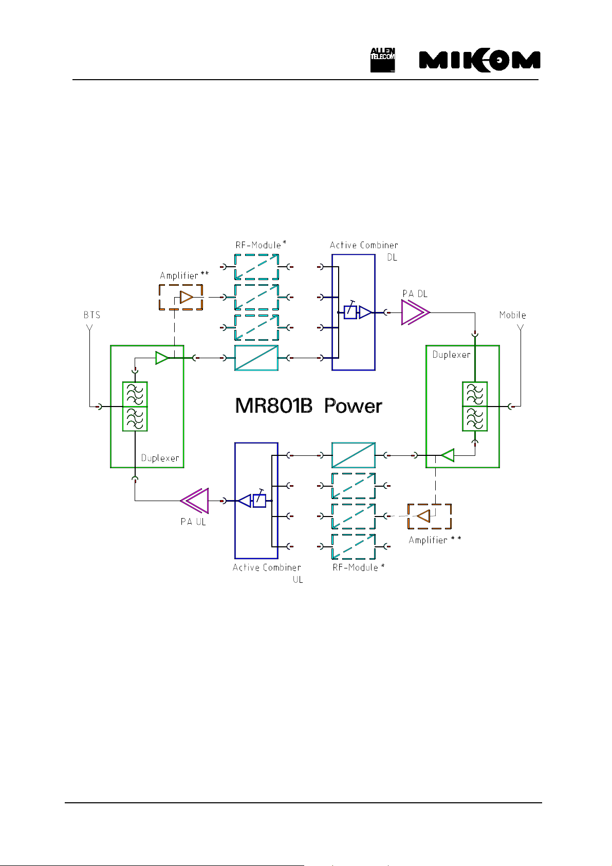
2 Functional description
The Repeater MR801B Power can be equipped from one to four bands or channels.
The following block diagram shall illustrate the configuration of the system.
*: one physical module contains UL and DL
**: with more than two channels, the amplifiers are included; both are in one housing
figure 2-1 Block diagram of MR801B Power
M0067A0A.doc Id.-No 151111 Page 14 02-JUNE-99

User’s manual for Repeater MR801B Power
2.1 General
The Repeater consists of two amplifier chains, which are connected antiparallel. The
receive path of one direction is connected to the transmit path of the other direction by a
frequency separation unit, in the following denominated as a duplexer, which combines
both signals to an antenna (See chapter 2.5).
After the duplexer the signals get to a pre-amplifier and afterwards to an RF module (See
chapter 2.2). Then the signals are combined by the active combiner (See chapter 2.6) and
afterwards amplified by the feed forward amplifier (See chapter 2.9), which provides the
required output power.
After the final amplifier a power detection measures the output power and controls the
gain. This is called Automatic Level Control (ALC) and keeps intermodulations below an
adjustable value. Finally, the signals are fed to the built-in antenna of the Repeater.
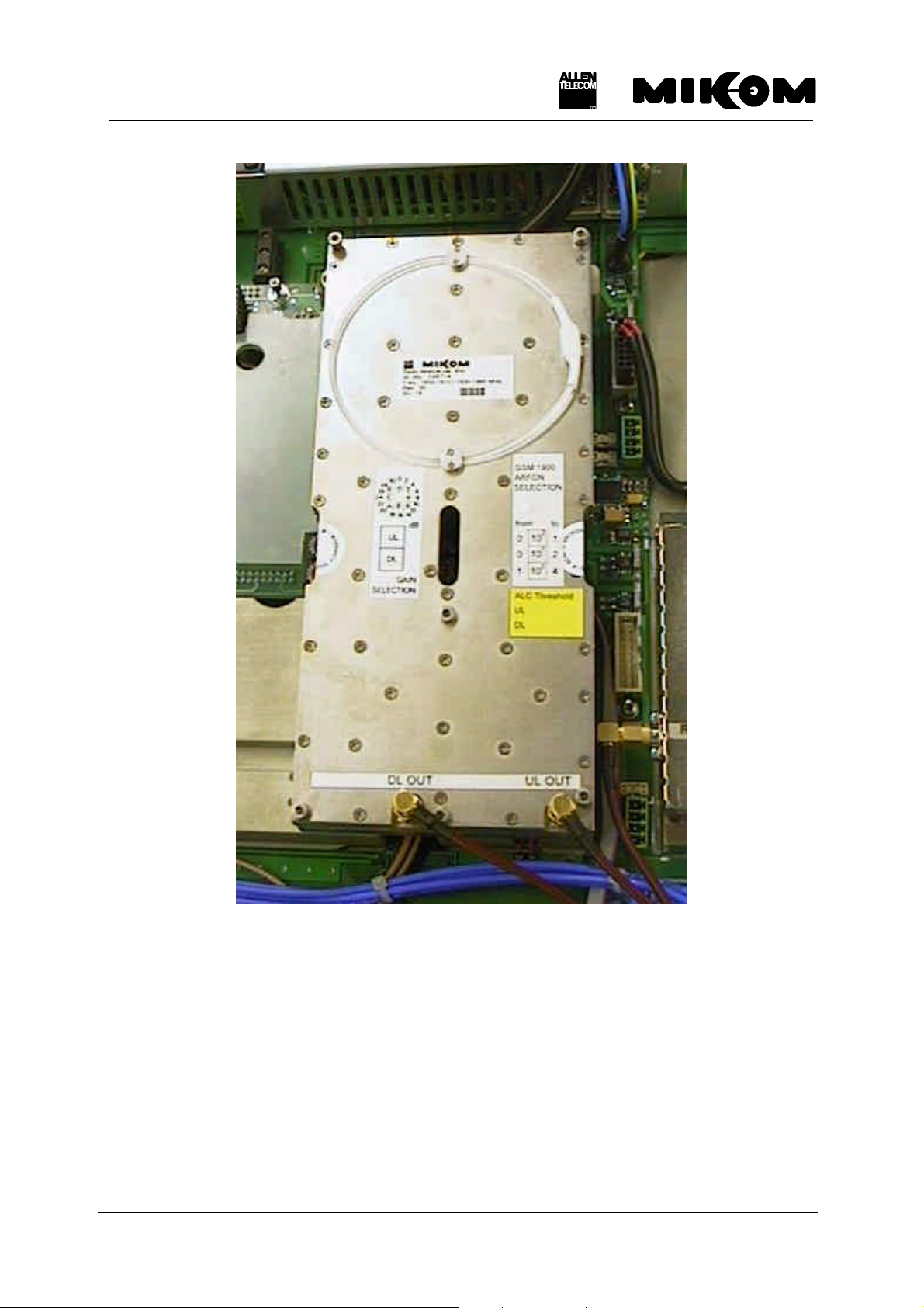
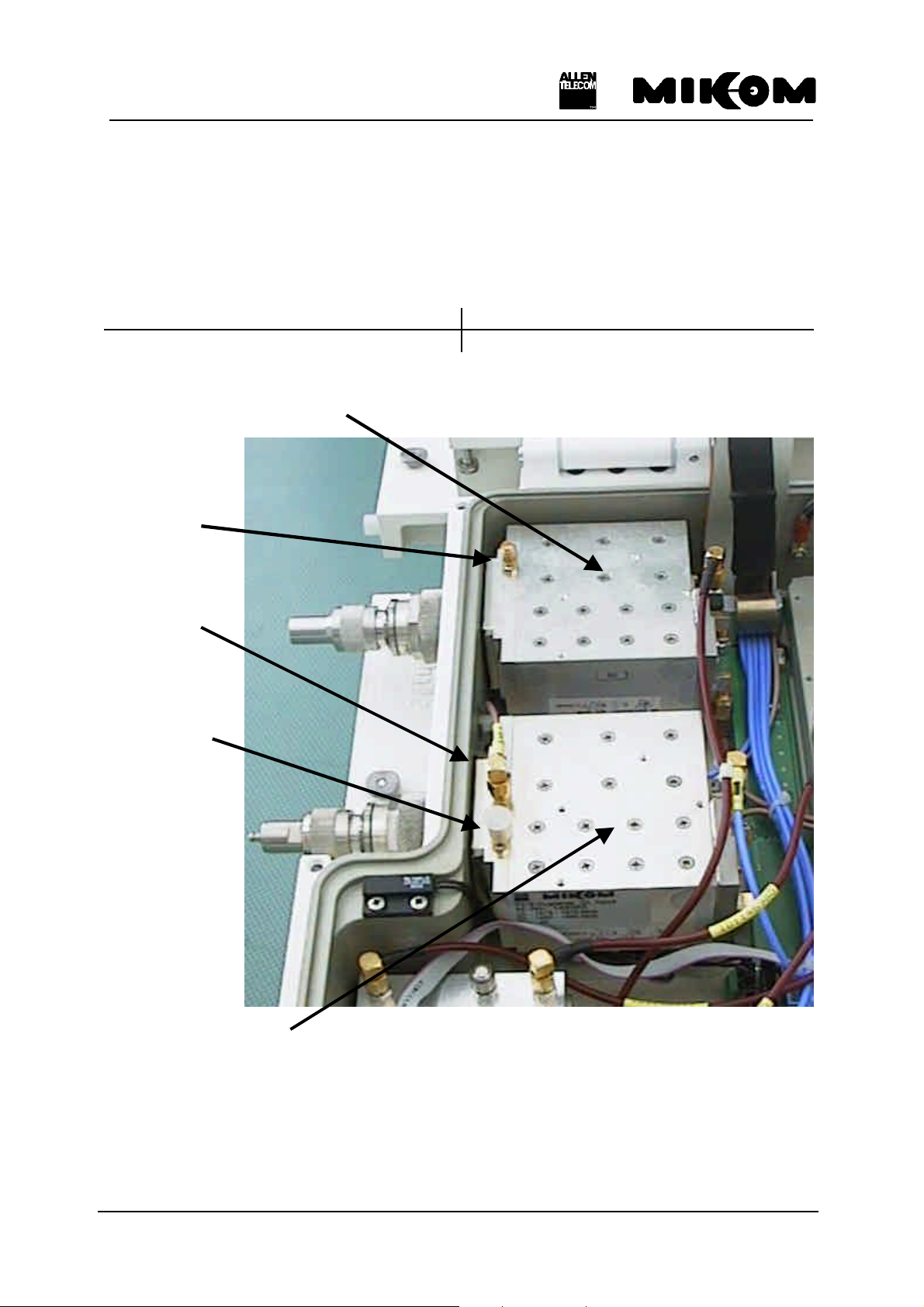
2.2 RF modules
The task of the RF modules is to amplify the receive signals and to convert them into an
intermediate frequency. The signals, then, proceed a filter stage comprising of highly selective
filters, and run through a digital controllable attenuator. The attenuation can be set in steps of
2 dB, locally or remotely. By using the same synthesizer frequency, that was used to convert
the signals down to intermediate frequency, the intermediate frequency is mixed up to the
original frequency.
The synthesizer is controlled via an I²C-Bus. In case of a breakdown in mains, gain and
frequency data are non-volatile stored in an EEPROM on board.
See figure 2-2 Top view of an RF module for an exemplary channel or band module.
M0067A0A.doc Id.-No 151111 Page 15 02-JUNE-99
User’s manual for Repeater MR801B Power
figure 2-2 Top view of an RF module
M0067A0A.doc Id.-No 151111 Page 16 02-JUNE-99
User’s manual for Repeater MR801B Power
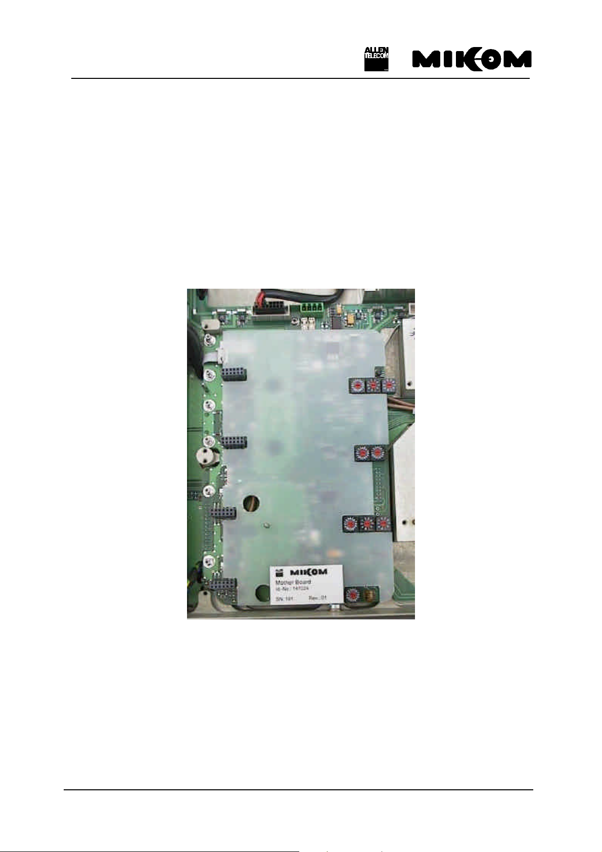
2.3 Mother board
The function of the mother board is the communication between the RF modules and the
control module via the I²C-Bus.
In the three and four channel configuration of the Repeater there is a mother board on the left
and on the right side, whereas in the one and two channel configuration there is only one
mother board implemented on the right side of the Repeater.
Mother boards are located underneath the RF modules.
figure 2-3 Top view of a mother board
M0067A0A.doc Id.-No 151111 Page 17 02-JUNE-99
User’s manual for Repeater MR801B Power
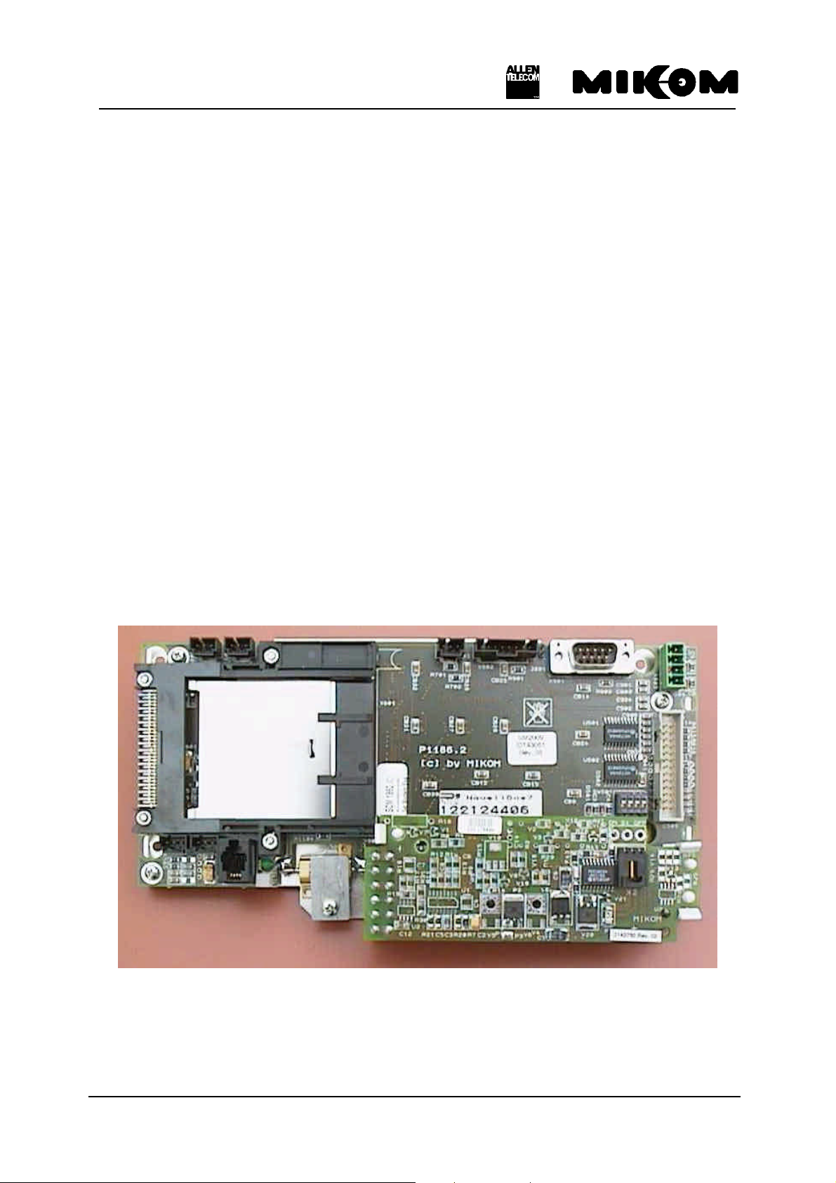
2.4 Control module SM 2009
The control module SM 2009 is a DOS compatible micro computer. The whole
communication between the operator and the Repeater can be done via the control module. By
using either the RS232 interface in connection with a modem card and a mobile the Repeater
can be controlled remotely or locally by using a VT100 terminal, i.e. a PC emulating the
VT100 terminal.
Frequency and gain, power down of RF stages and ALC can be controlled and status
messages can be received remotely. In case a modem or a mobile is connected, automatic
alarm messages can be received.
The data transfer between the control module SM 2009 and the mother board is realized by
the I²C-Bus system.
The I²C-Bus concept was developed by Philips for the serial connection of integrated circuits
within one device. Two wires, SDA - serial data and SCL - serial clock, carry information
between the devices connected to the bus. Each device is recognized by a unique address and
can operate either as transmitter or receiver.
All MR801B Power configuration parameters are stored in an EEPROM on the control
module if a power supply failure occurs.
figure 2-4 Top view of the control module
M0067A0A.doc Id.-No 151111 Page 18 02-JUNE-99
User’s manual for Repeater MR801B Power
2.5 Duplexer
The task of the duplexer is to isolate uplink from downlink, i.e. isolate transmit path from
receive path. The pass bandwidth of the duplexer is the entire width of the uplink band and
the downlink band.
UL frequency DL frequency
824 - 849 MHz 869 - 894 MHz
Duplexer with connector to mobile side
30 dB
coupler
20 dB
coupler
30 dB
coupler
Duplexer with connector to BTS side
figure 2-5 Top view of the duplexers
M0067A0A.doc Id.-No 151111 Page 19 02-JUNE-99
User’s manual for Repeater MR801B Power
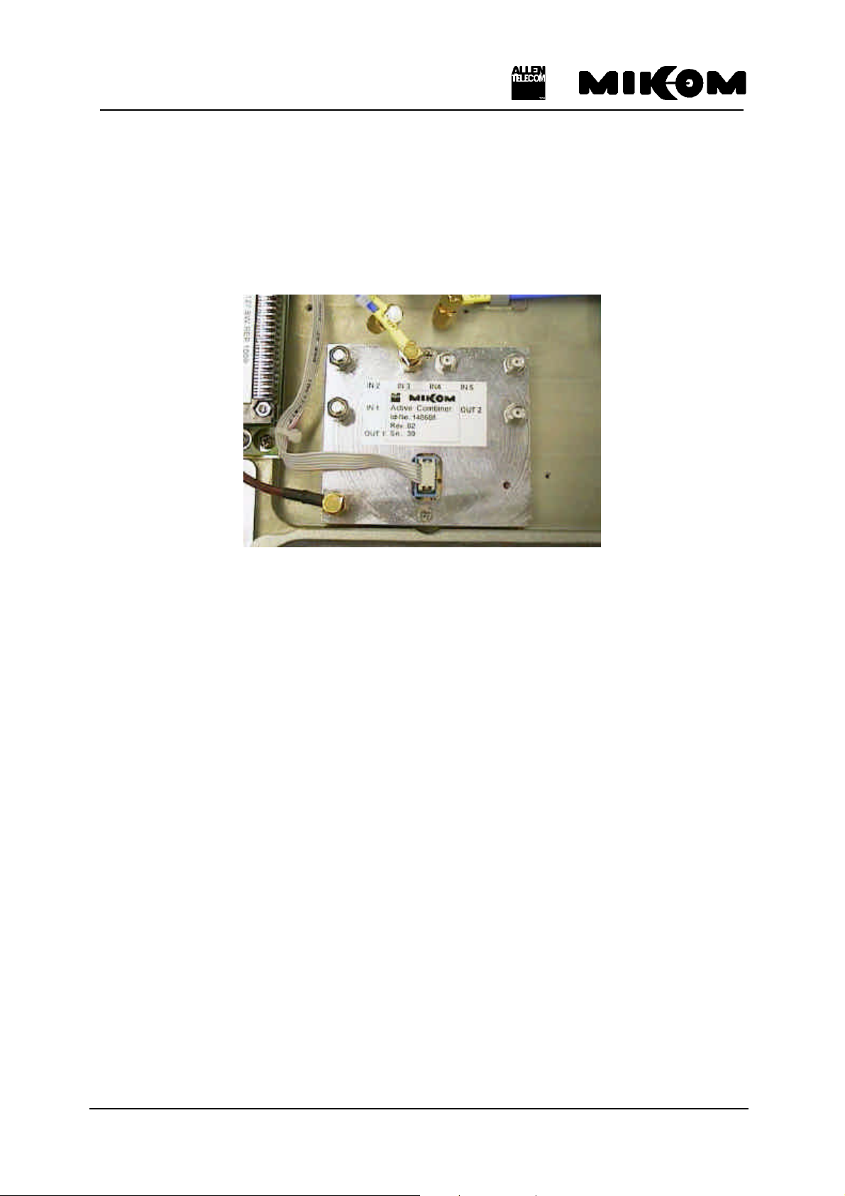
2.6 Active combiner
After passing through the RF modules, the signals will be combined by the active combiner
module in the UL and in the DL path. The active combiner will be followed by the feed
forward amplifier.
figure 2-6 Top view of the active combiner module
2.7 Measuring aids
With built-in RF probes test signals can be applied or detected. The probes provide a coupling
factor of 30 dB respectivly 20 dB. Each duplexer (uplink and downlink) is equipped with one
30 dB coupler, the UL Input duplexer additionally with a 20 dB coupler for a modem or
mobile (See chapter 4 Optional equipment). This facilitates measurements under all
operational conditions, while an antenna or a dummy load may be connected.
The position of the couplers on the duplexers is shown in figure 2-5 Top view of the
duplexers.
M0067A0A.doc Id.-No 151111 Page 20 02-JUNE-99
User’s manual for Repeater MR801B Power
power socket
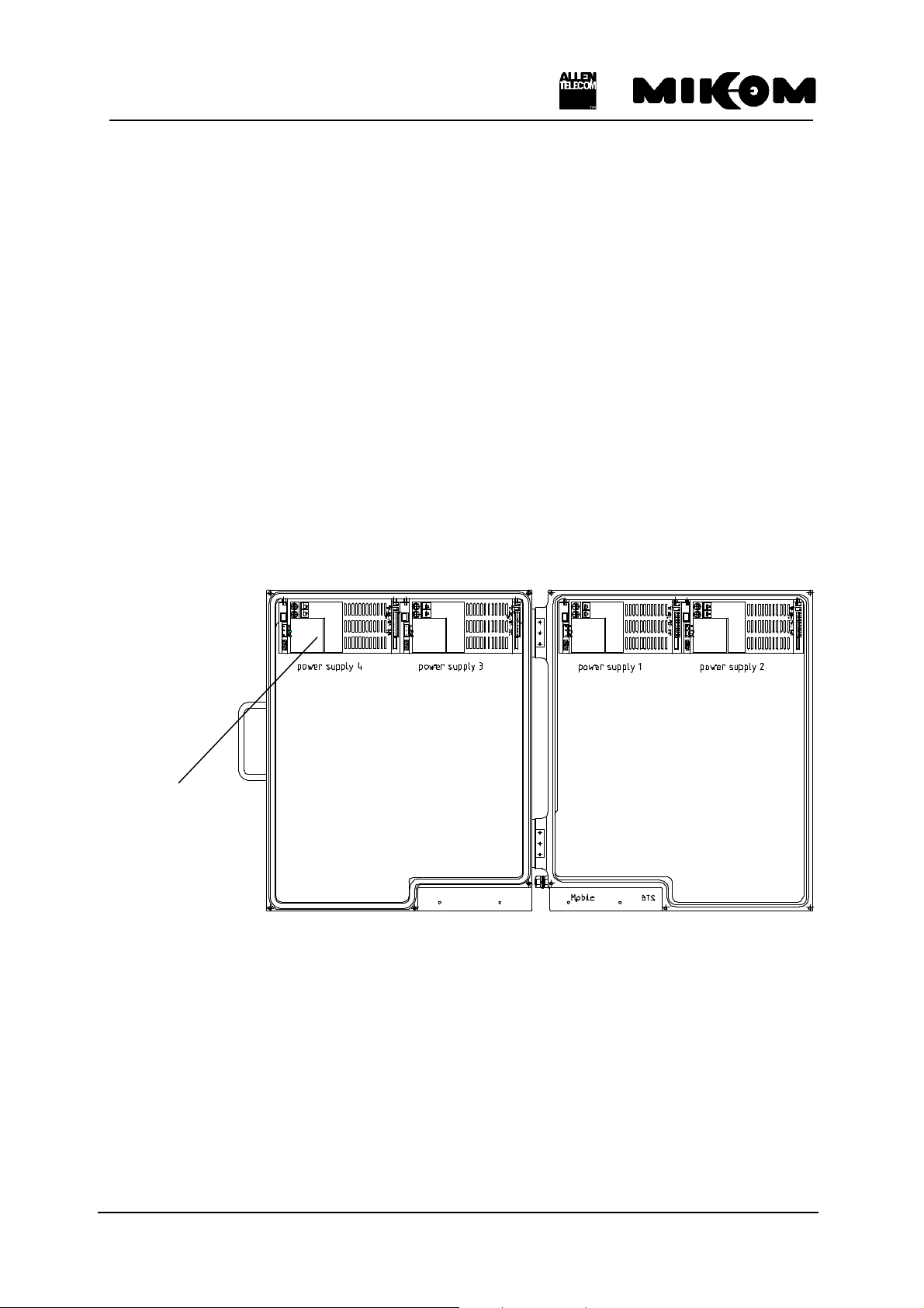
2.8 Power supply
For the MR801B Power four power supplies are necessary.
Power supplies are available with different mains power. See list below for available power
supplies.
• 115 VAC ± 15% / 40 - 65 Hz
• 230 VAC ± 15% / 40 - 65 Hz
• 185 - 320 VAC / 40 - 65 Hz
• 24 VDC
• 42 to 60 VDC
• 80 to 130 VDC
The following figure shows the mounting position of the power supplies in the MR801B
Power cabinet.
(service connector)
figure 2-7 Mounting position of power supplies
Each power supply is equipped with a power socket, protected with two fuses. Each power
supply can be switched on or off by means of an external switch. The modules of the Repeater
are voltage free if all power supplies are switched off. The power socket, however, is still
provided with mains power.
See figure 2-8 ON / OFF position of external switch.
M0067A0A.doc Id.-No 151111 Page 21 02-JUNE-99
User’s manual for Repeater MR801B Power
figure 2-8 ON / OFF position of external switch
F Note: To switch the whole Repeater voltage free, you have to remove the
fuses F1 and F2 on the screw terminal.
The power supply is factory-set.
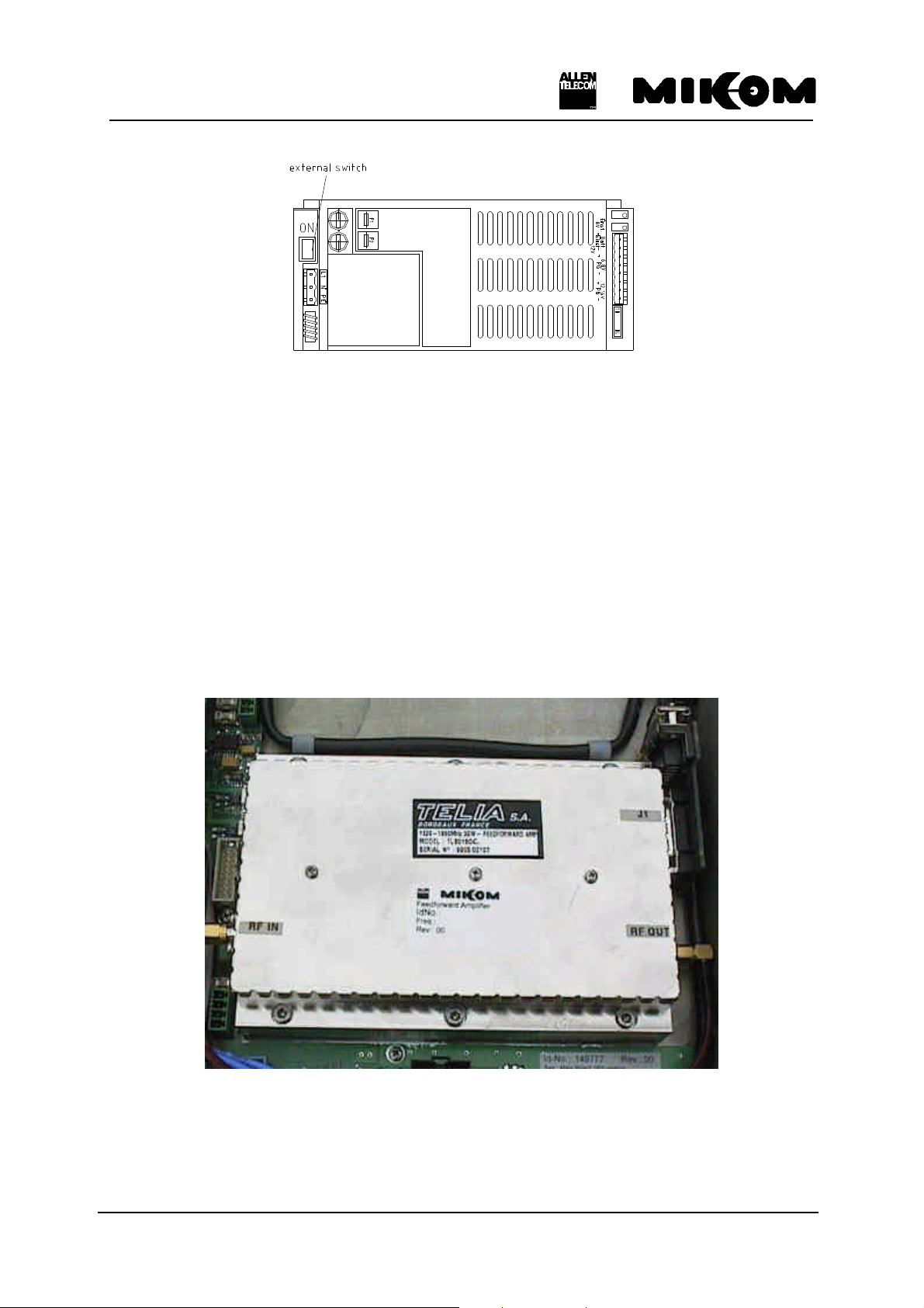
2.9 Feed forward amplifier
The feed forward amplifier is the final stage which enables high output power as well as a
high ICP3. One amplifier has to be installed for each path, the uplink and downlink.
figure 2-9 Top view of the feed forward amplifier
M0067A0A.doc Id.-No 151111 Page 22 02-JUNE-99
User’s manual for Repeater MR801B Power
3 Functions and features
3.1 Band and channel selectivity
The selectivity is achieved by highly selective filters in the IF part of the band / channel
modules.
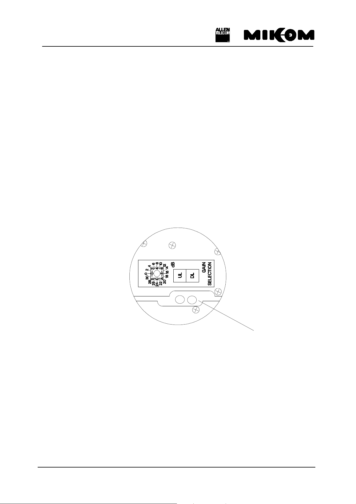
3.2 Gain setting
The gain can be changed by introducing attenuation into the amplifier chain. By using a rotary
switch the attenuation can be adjusted locally in the range from 0 dB to 30 dB maximum in
steps of 2 dB. The attenuation can be set for the UL and DL path separately.
The rotary switches are mounted on the mother board. These switches are accessible through
the long hole between the two RF modules (see figure 3-1 Position of rotary switches). They
can be adjusted easily by means of a small screwdriver.
long hole
figure 3-1 Position of rotary switches
For remote control an RS232 interface can be used to set the gain.
The functions of the control module may be used locally by means of a VT100 terminal or a
personal computer emulating the VT100 terminal. See also chapter 7.2, which deals with
settings of operational parameters.
M0067A0A.doc Id.-No 151111 Page 23 02-JUNE-99
 Loading...