


TM
ION
rel. 24-10
-B Series
User Manual


© Copyright Andrew Wireless Systems Srl
Andrew Wireless Systems Srl
Via Pier De Crescenzi 40
48018 Faenza, Italy
Tel: +39 0546 697111
Fax: +39 0546 682768
This publication is issued to provide outline information and
is not aimed to be part of any offer and contract.
The Company has a policy of continuous product
development and improvement and we therefore reserve
the right to vary information quoted without prior notice.
System and Customer care is available world-wide through
our network of Experts.
The company is certifi ed ISO 9001 and ISO14000.
3MN024-010

Index
1. Introducing ION-B 10
1. Introducing ION-B 11
1.1 The Features 11
1.2 Brief Description of ION-B 11
1.3 ION-B Features 12
1.4 ION-B Typical Applications 13
2. Equipment Overview 16
2. Equipment Overview 17
2.1 Introduction 17
2.2. The ION-B Remote Unit and its relevant accessories 17
2.3. The ION-B Master Unit 19
2.4. ION-B additional options 22
2.5. Block Diagrams 24
3. TFAx Remote Unit 29
3.1. Introduction 30
The Main Tasks of the TFAx Unit: 30
Different Types of Remote Units 31
3.2. Case A Remote Unit 33
Dimensions and Weight: 33
RF ports: 33
Optical ports: 33
Visual Alarms: 34
Dry Contact Alarms: 34
Power Supply 34
Warnings (to be read before Remote Units are installed) 35
Dealing with optical output ports 35
Handling optical connections 35
TFAx Case A installation 36
Installing a Case A Remote Unit WITHOUT the TKA kit 36
Installation of the Case A Remote Unit WITH the TKA04 installation kit 38
TFAx Case A Start-Up 44
TFAx Case A Troubleshooting 44
3.3. Case B Remote Unit 45
Dimensions and Weight: 45
RF ports: 46
Optical ports: 46
Visual Alarms: 46
Dry Contact Alarms: 46
Power Supply 47
Dealing with optical output ports 48
Handling optical connections 48
TFAx Case B installation 49
Installing a Case B Remote Unit WITHOUT the TKA kit 49
Installation of the Case B Remote Unit WITH the TKA04 installation kit 51
TFAx Case B Start-Up 52
TFAx Case B Troubleshooting 57
4
ION-B User Manual

Quick troubleshooting procedure 62
Dry-contact troubleshooting 62
Fibre optic DL troubleshooting 63
3.4. Case R Remote Unit 65
Dimensions and Weight 65
RF ports: 66
Optical ports: 66
Visual alarms: 66
External alarms 66
Power supply: 67
Warnings (to be read before Remote Units are installed) 67
Dealing with optical output ports 67
Choosing a proper installation site for the Remote Units 67
Handling optical connections 67
TFAx Case-R installation 68
TFAx Case R Troubleshooting 72
3.5. Case-R2 Remote Unit 73
Dimensions and Weight 73
RF ports: 74
Optical ports: 74
Visual alarms: 74
External alarms 74
Power supply: 75
Warnings (to be read before Remote Units are installed) 75
Dealing with optical output ports 75
Choosing a proper installation site for the Remote Units 75
Handling optical connections 75
TFAx Case-R2 installation 76
TFAx Case R2 start-up 80
TFAx Case-R or Case-R2 troubleshooting 81
Quick troubleshooting procedure 85
Dry-contact troubleshooting 85
Fibre optic DL troubleshooting 85
3.7. Case F Remote Unit 87
Dimensions and Weight 87
RF ports: 88
Optical ports: 88
Visual alarms: 88
External alarms 88
Power supply: 88
Warnings (to be read before Remote Units are installed) 89
TFAx Case-F installation 90
TFAx Case F start-up 93
TFAx Case F troubleshooting 93
Quick troubleshooting procedure 95
Fibre optic DL troubleshooting 95
4. Rack-based Master Unit 99
4.1. TPRNx4 Subrack 101
Major TPRN features 101
TPRN models 101
220 Vac powered sub-racks (TPRN14 / TPRN24) 102
-48Vdc powered sub-rack (TPRN34) 102
TPRN power supply 103
Universal mains 103
5MN024-010

-48 Vdc 103
TPRN ports 104
RS232 serial port 104
RS485 port 105
Sub-D 15 poles male connector 105
PIN 106
Name 106
Meaning 106
TPRN alarms 108
Warning (recommended for system designing and installing) 108
Providing correct heat dissipation 108
Minimizing equipment costs 108
TPRN Installation 109
TPRN Troubleshooting 111
4.2. Fast MiniRack, TPRF31 113
Major TPRN Features 113
Dimensions and Weight 114
On/Off Switch and Power Supply 114
Reset and Store/Clear buttons 114
Reset 114
Store/Clear 114
Visual Alarms 115
TPRF31 Ports 115
RS232 Serial Port 115
RS485 Port 116
Auxiliary Inputs 118
External Alarms 119
Warning (recommended when designing or installing) 120
Providing correct heat dissipation 120
TPRF31 Installation 120
Mounting the TPRF31 on a wall 122
TPRF31 Start-Up 122
TPRF31 Troubleshooting 124
4.3. Master Optical TRX, TFLN 127
Main tasks carried out by the TFLN module 127
Downlink (DL): 127
Uplink (UL): 127
RF ports 127
Optical ports 127
TFLN Visual Alarms 128
TFLN power supply 128
Warnings (to be read before TFLN installation) 128
Dealing with optical output ports 128
Handling optical connections 129
Inserting or removing TFLN modules 129
TFLN Positioning 130
TFLN Installation 130
TFLN Start-Up 131
Removing a TFLN Module 133
TFLN Troubleshooting 133
Quick Troubleshooting Procedure 134
Fibre Optic UL Troubleshooting 134
4.4. Two-way Splitter/Combiner, TLCN2 137
Description: 137
RF Ports 137
TLCN2 Main Applications 137
TLCN2 Insertion Loss 138
6
ION-B User Manual

Warnings 138
TLCN2 Installation 138
4.5. Four-way Splitter/Combiner,TLCN4 139
Description: 139
RF Ports: 139
TLCN4 Main Applications 139
TLCN4 Insertion Loss 140
Warnings 140
TLCN4 Installation 140
4.6. RF Dual Band Coupler TLDN 141
Description: 141
RF Ports 141
TLDN Main Applications 141
TLDN Insertion Loss 142
Warnings 142
TLDN Installation 142
4.7. RF Tri Band Coupler TLTN 143
Description: 143
TLTN Models 143
RF orts 143
TLTN Main Applications 144
TLTN Insertion Loss 144
Warnings 144
TLTN Installation 144
4.8. RF Duplexer, TDPN 145
Description: 145
RF Ports 145
TDPN Main Applications 145
TDPN Insertion Loss 145
Warnings 145
TDPN Installation 146
4.9. Base Station Interface TBSI 147
Description 147
RF Ports 147
TBSI Main Applications 147
TBSI Insertion Loss 148
Warnings 148
TBSI Installation 148
4.10. Power Limiter TMPx-10 149
Description 149
RF Ports 149
TMP Main Applications 149
TMP Visual Alarms 149
TMP Power Supply 150
TMP Insertion Loss 150
Warnings 150
Inserting or Removing TMP Modules 150
Before to install the TMP Module 150
Setting the GSM 900 MHz / DCS 1800 MHz jumper (only for TMP2-10) 150
TMP Installation 151
Removing a TMP Module 152
TMP Troubleshooting 152
Quick Troubleshooting Procedure 152
7MN024-010

5. Confi guration Examples 155
5. Confi guration Examples 156
5.1 Introduction 156
5.2. Multi-operator applications 156
5.3. Multi-sector applications 159
5.4. Fast MiniRack applications 162
6. Warning and Safety Requirements 163
6. Warning and Safety Requirements 164
Environmental Conditions 164
Installation Site Features 164
Safety and Precautions During Installation or Maintenance 165
Power Supply Connection 166
Safety and Precautions for Lasers 166
Health and Safety Warnings 167
RSS Canadian standards 167
Electromagnetic Fields and RF Power 167
Warning Labels 171
7. TECHNICAL SUPPORT 172
7. TECHNICAL SUPPORT 173
Returning Equipment 174
Appendixes 175
Appendix A: System Commissioning 176
Appendix B: EU Guidelines for WEEE Disposal 180
Disposal Guidelines 180
8
ION-B User Manual

9MN024-010

1. Introducing ION-B
10
ION-B User Manual
1. Introducing ION-B
1.1 The Features
ION-B is an innovative platform designed in order to provide an effective and fl exible
coverage to a large variety of indoor scenarios.
Thanks to its high modularity, its low power consumption, and its full-transparency to protocols
and modulation formats, ION-B is the perfect plug&play solution to distribute any wireless
standard (including GSM, GPRS, EDGE, CDMA, W-CDMA, and WLAN IEEE 802.11b/g) to the inbuilding environments requiring reliable and interference-free communications, as well as high
traffi c capacity and maximum fl exibility about future expansions.
These unique features make the ION-B platform suitable also for applications to critical areas
experiencing diffi culties in establishing and keeping phone calls, while its compact design
always guarantees a minimum aesthetic impact.
1.2 Brief Description of ION-B
ION-B is a Distributed Antenna System (DAS) based on the Radio-over-Fibre (RoF) technology,
and capable of carrying wireless mobile signals through the 800MHz - 2500MHz frequency
range regardless of their protocol and their modulation format.
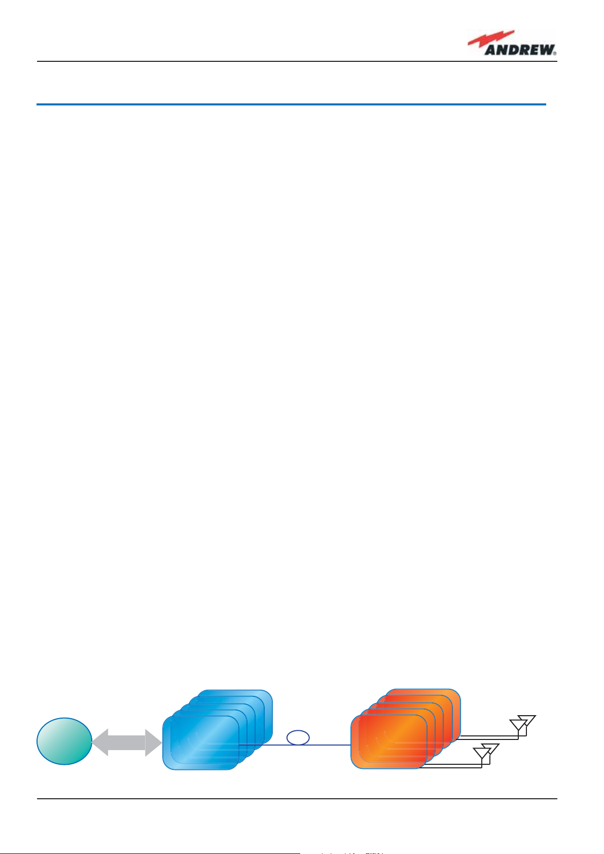
The system has two basic components, a Master Unit and a Remote Unit. The Master Unit
is made of one or more subracks typically connected to the BTS (Base Tranceiver Station)
through either a repeater (RF interface) or a coaxial cable.
Each Remote Unit is connected with a dedicated pair of single-mode optical fi bres (one for
UL and one for DL) to the Master Unit. These optical fi bres work on 1310 nm wavelenght and
provide low losses and almost unlimited bandwidth, available for future system developments.
ION-B is a modular system whose basic components are:
• one Master Unit made of one or more subracks, each providing 12 module slots. Each
slot can host either an active or a RF passive device (chosen among the wide range of ION-B
options), in order to meet the planned design requirements;
BTS
RF Interface
TFLN
Figure 1: ION-B system block diagram
Unit
Remote
11MN024-010

• a variable number of Remote Units (TFAx), whose function is feeding the antenna passive
network;
• a proper number of indoor antennas, suitable to provide radio coverage to the area.
ION-B is fully compatible with any type of indoor antennas;
• the optical cables required to connect the 19” subracks to the TFAx.
1.3 ION-B Features
The following lines report a brief summary of ION-B main features:
• multiband 2G, 2.5G and 3G – 802.11b WLAN compatible: ION-B is completely transparent
to any transmission protocol and modulation format, and it can distribute any 2G, 2.5G,
3G wireless standard. In addition, it allows to carry also the WLAN (802.11b/g) service
over the same infrastructure;
• modular confi guration for fl exible design: by properly setting some parameters like
the amount of RUs and the antenna locations, the ION-B architecture can follow the
environment specifi c features in order to obtain the most effective radio-coverage of the
indoor area. The modularity of the system allows easy modifi cations for future growth and
increasing traffi c;
• easy to install: the intelligent plug & play ION-B system includes an Automatic Gain
Control (AGC), that eliminates system gain variations regardless of optical loss. This avoids
the need for fi eld adjustments, thus reducing design, installation and optimization time.
• low-power consumption: establishing a “quasi line-of-sight propagation” towards all
mobile phones inside the area, ION-B works with low power levels. Low power levels
have two great advantages: 1) allow mobile phones to work at lower power levels, thus
limiting the radiated emissions and increasing their battery life; 2) allow a better control of
interference effects between adiacent cells.
• central supervision functions: all individual alarms of ION-B system are stored in an internal
fl ash memory, and available to both local and remote connections. Detailed alarm
information is provided by special software (i.e. by Supervision or Maintenance software
tools) running on a locally connected host, as well as any information about alarm status
and alarm history is available to remote connections via TCP/IP protocols, SNMP agent,
or HTTP servers. This alarm information is visible also by means of LEDs present on the front
panels of both the MU and the RUs;
• multiple-carriers system: there are no restrictions on the number of carriers that the ION-B
can convey. Obviously, the more carriers per service, the less power per carrier;
• remote power supply: in case mains cannot be used for the Remote Units, ION-B offers a
centralised power supply option, which distributes both a DC low-voltage (-48V) power
and the optical signals through a composite fi bre optic/copper cable;
• wide variety of RF passive devices: the connections between the DAS and the local
BTSs are able to be arranged so as to get the best fi t for the customers needs. ION-
12
ION-B User Manual

B equipment provides RF splitters/combiners, cross band couplers, attenuators, and
duplexers for UL/DL paths, thus allowing maximum in design fl exibility;
• high reliability: high MTBF (Mean Time Between Failure).
1.4 ION-B Typical Applications
Due to its unique features, the ION-B is an ideal solution for radio coverage in a variety of
situations:
• Multi-operator shared infrastructures: each mobile operator has its own carrier
which needs to be transported without interfering the others. The ION-B is capable
of transmitting multiple carriers simultaneously while providing independent level
adjustments for each of them, ensuring maximum performance and reducing
infrastructure costs.
• High rise buildings: RF signals from surrounding macrocells or external BTSs are usually quite
strong inside high rise buildings and can cause so much interference that indoor mobile
communications often become impossible. By strategically placing antennas along the
exterior walls of the building, the signal to noise ratio can be optimised. This interference
control solves many problems, such as the “ping pong” effect that sometimes is
experienced when a mobile frequently changes from indoor to outdoor coverage.
• Exhibitions, conventions, and shopping centres: the critical aspect of these environments
is their high traffi c loads, which are furthermore also highly variable. Thus, the main goal
in these cases is to set up radio coverage enabling the effective management of these
variable traffi c loads, with neither undervalued nor overvalued infrastructure expenses.
A unique feature of the ION-B is that RF frequencies can be allocated quickly when and
where they are needed, thus reducing implementation costs. This makes the ION-B an
ideal solution for temporary or last minute requests (such as conferences).
• Airports: require both modular and fl exible radio coverage in order to meet their current
needs while also foreseeing future expansions. The ION-B is able to manage heavy
traffi c loads, providing a high level of quality with minimum environmental impacts, its
modularity also allows for future expansions.
• Corporate buildings: inside a corporate building, frequent disruptions during mobile
communications may limit business transactions. These environments are often complex
and densely populated while having specifi c requirements: heavy traffi c capacity, high
expectations regarding quality of service, full compatibility with wireless standards and
future expandability. The ION-B guarantees high quality radio coverage in all of the
above conditions and maintains maximum fl exibility while managing any possible traffi c
conditions.
• Subways and densely populated metropolitan areas: These areas are distinguished
by large surface areas, and may require RUs to be placed far away from the BTSs.
The ION-B guarantees signal integrity for distances up to 3km, while through the
13MN024-010

wideband interconnect link option, distances of 20km can be reached. Moreover, these
environments require gradual investments, because initially operators tend to provide
radio coverage only in the busiest areas, and then extend it in order to reach complete
coverage later. The modularity of the ION-B helps operators to gradually expand the
system. Often, large cities set up seamless and reliable radio systems for emergency
services. In these cases, the required RF infrastructure needs to be unobstrusive and
environmental friendly; this can be achieved using an ION-B DAS. When redundancy
is required, two interleaved ION-B systems can be used, management and supervision
for these systems can be remotely established by means of an external modem and an
open protocol such as SNMP.
14
ION-B User Manual

15MN024-010

2. Equipment Overview
16
ION-B User Manual
2. Equipment Overview
2.1 Introduction
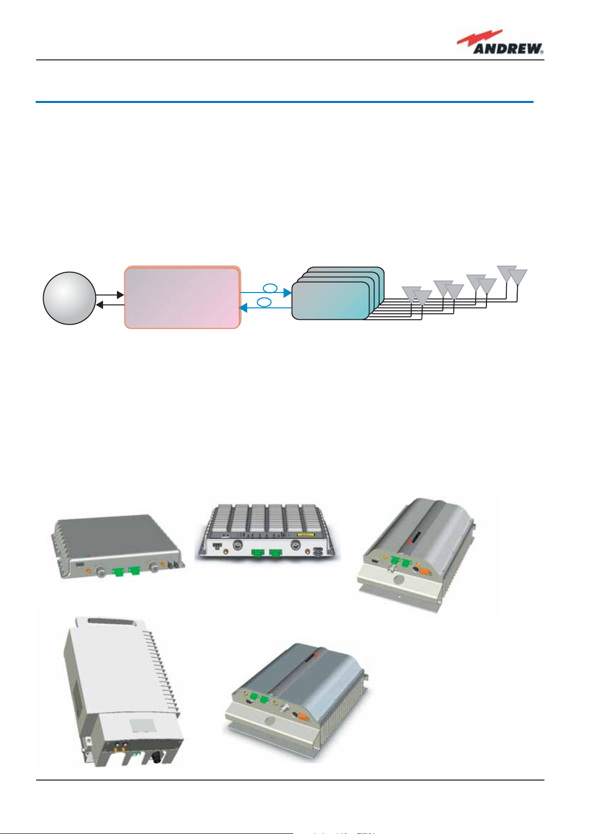
The basic components of an ION-B system (please refer to fi g. 2.1.) are the following:
• a Master Unit, able to bring the mobile signals from the BTS to different Remote Units and
vice-versa, thus remotising the distribution and collection of any mobile signals via fi beroptic
cables;
• a variable number of Remote Units, conveying and receiving mobile signals through lowpower antennas.
BTS
A brief introduction to the main components of the ION-B system’s Master and Remote
Units is presented in the following text. The details of each component can be found in the
subsequent sections of this manual.
ION-B Master Unit
Fig. 2.1: Basic scheme of an ION-B system
Remote Unit
TFAx
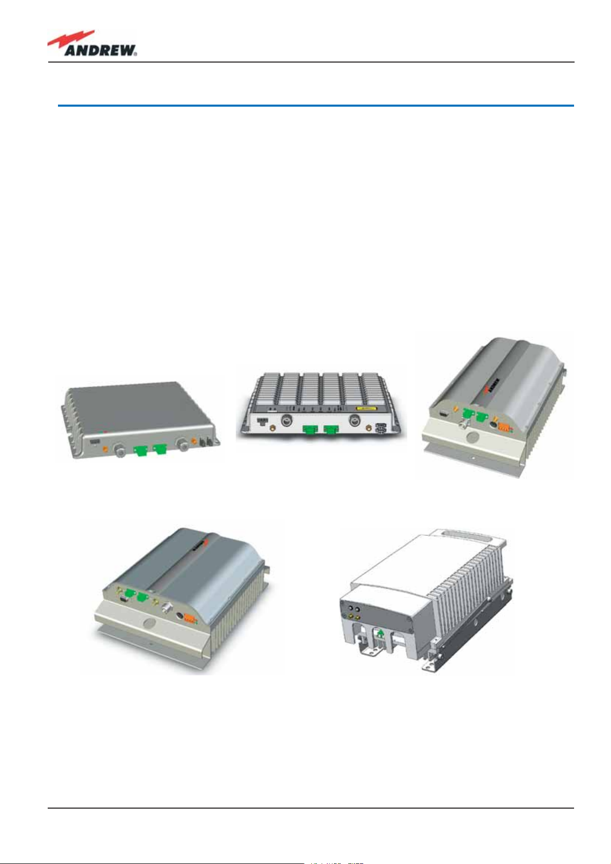
2.2. The ION-B Remote Unit and its relevant accessories
(b)
(a)
(c)
(e)
(d)
Fig. 2.2:
Different versions of the
ION-B Remote Units:
(a) Case-A Remote Unit
(b) Case-B Remote Unit;
(c) Case -R Remote Unit;
(d) Case-R2 Remote Unit;
(e) Case-F Remote Unit
17MN024-010

The Remote Unit (TFAx) is a device which provides optical-to-electrical downlink conversion
and electrical-o-optical uplink conversion, thus allowing a bidirectional transmission of
signals between the Master Unit and the remote antennas. It is available in 3 different power
confi gurations (Low/Medium/High), housed by 4 different architectures (Case B, Case R, Case
R2 and Case F), so as to fulfi l different coverage and band requirements.
In downlink, each TFAx receives an optical signal from the Master Unit, performs an optical-toRF conversion, and transmits the resulting signal to the 2 antenna ports.
In uplink, it receives an RF signal from the remote antennas, provides an RF-to-optical
conversion, and conveys the converted signal to the Master Unit through optical fi bres.
The ION_B Remote Units are available both with power supply 90÷264 Vac and with power
supply -72÷-36 Vdc. Each ION-B Remote Unit is provided with a suitable external power
adapter (TPSNx: please refer to table 2.1).
Last, each ION-B Remote Unit has a wideband auxiliary channel, which can be exploited for
dedicated RF distribution.
Remote UnitS and accessories
Unit name/
Module name
TFAx-case A
TFAx Case B
TFAx Case R
TFAx Case R2
TFAx Case F
TFBWx
TKA04
TPSN 1-40
TPSN 1-80
Description Dimensions (L x W x H)
Remote Unit
Remote Unit
Remote Unit
Remote Unit
Remote Unit
WLAN booster
Remote Unit installation kit
External power supply
External power supply
200 x 240 x 38 (mm)
240 x 240 x 38 (mm)
330 x 200 x 122.5 (mm)
330 x 250 x 122.5 (mm)
546 x 253 x 207 (mm)
240 x 200 x 38 (mm)
340 x 240 x 55 (mm)
175 x 80 x 54 (mm)
18
TPSN 3-30
TPSN 3-80
External power supply
External power supply
Table 2.1: Different cases of ION-B Remote Units,
with dedicated ION-B accessories.
175 x 80 x 51 (mm)
ION-B User Manual
2.3. The ION-B Master Unit
The ION-B Master Unit is a widely-fl exible system. Its modular feature allows it to be developed
both for simple installation-friendly, unobstrusive applications to complex installations, involving
a virtually unlimited number of subracks, and distributed through several fl oors of a building or
through a 20km distance.
The following text presents a brief overview of the components of these units.
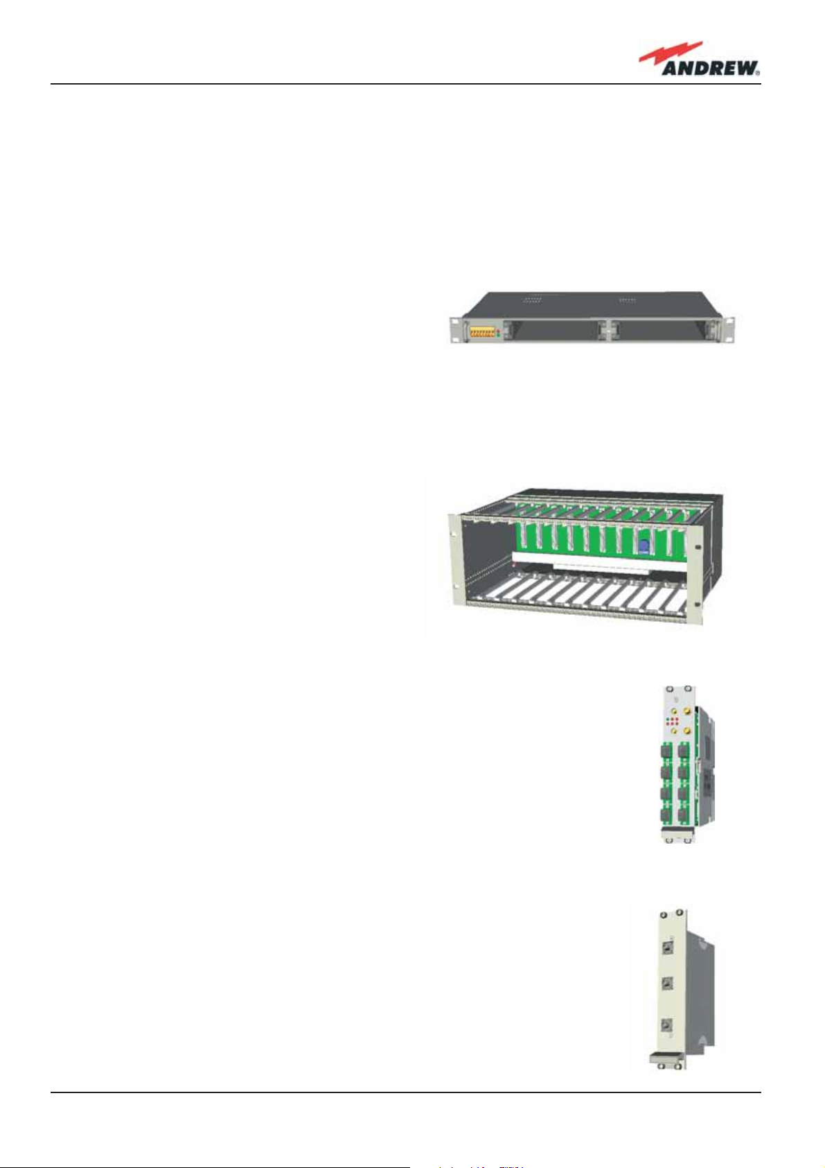
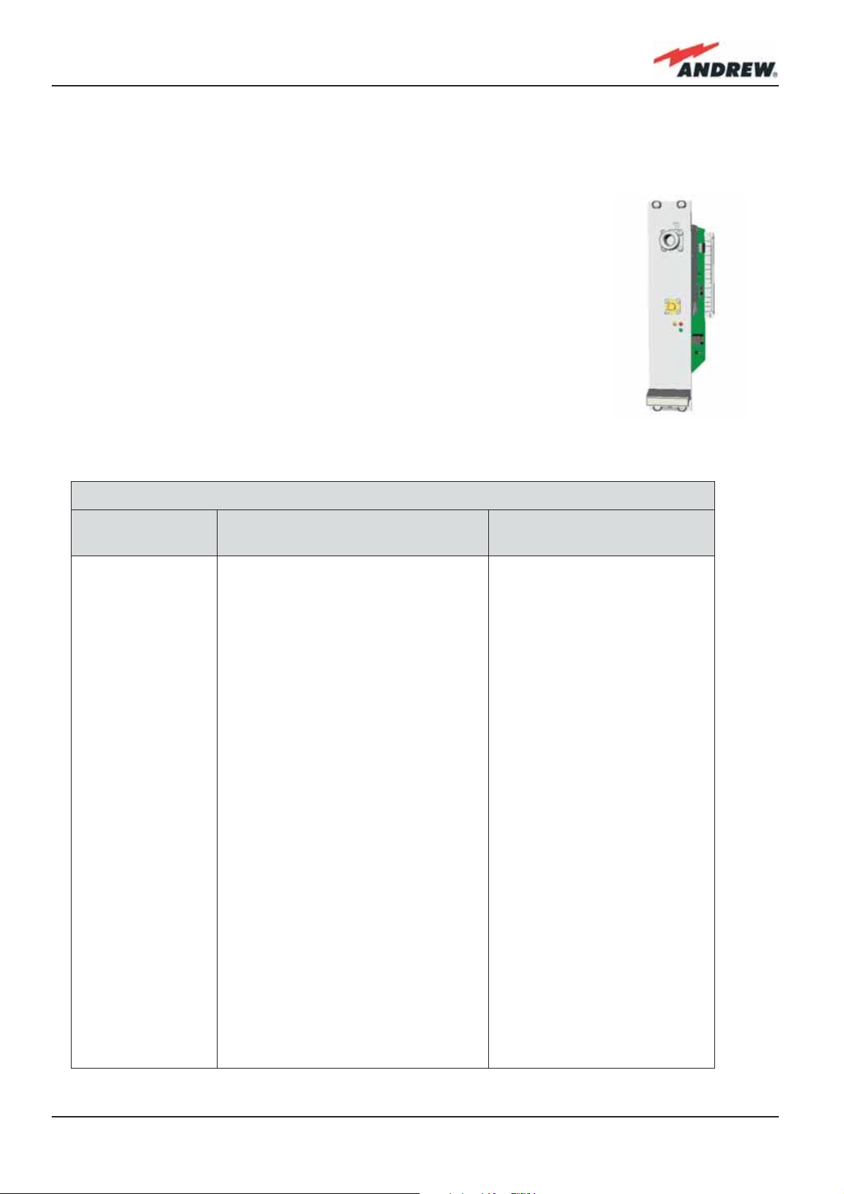
The TPRF31 Fast MiniRack is a 19” x 1HE fastMiniRack housing 2 slots: it can therefore
accommodate 2 of the single-slots (7TE x 4HE)
ION-B cards presented in the following. Thanks to
Fig. 2.3 TPRF31 subrack
its turnable brackets, the TPRF31 is suitable both
for wall and rack-mounting, and can therefore be used both as a stand-alone unit (for simple
ION-B installations) and as an integration of a bigger and more complex ION-B system .
The TPRN sub-rack is a 19”x 4HE subrack with 12
slots, each one sized 7TE x 4HE. As each ION-B
module takes up one or two slots, each Master
Unit can host up to 12 modules, depending on
the design confi guration and requirements.
Fig. 2.4 TPRN subrack
The Master Optical TRX (TFLN): in downlink, it provides an RF-to-optical
conversion of the signal coming from the BTS, and transmits it to 4 optical
outputs, so as to feed 4 TFAx. In uplink, it provides optical-to-RF conversion for
4 optical signals coming from the RUs, and it combines them into a single RF
output, while providing automatic gain control in order to balance the fi bre
losses. Module dimensions:
Width = 7TE, Height = 4HE (one slot in the master unit sub-rack).
The Duplexer (TDPN): it combines the downlink (DL) and the uplink (UL)
paths into a single one, while maintaining the required isolation. The module
dimensions are: Width = 7TE, Height = 4HE
Fig. 2.6 TDPN card
Fig. 2.5 TFLN card
19MN024-010
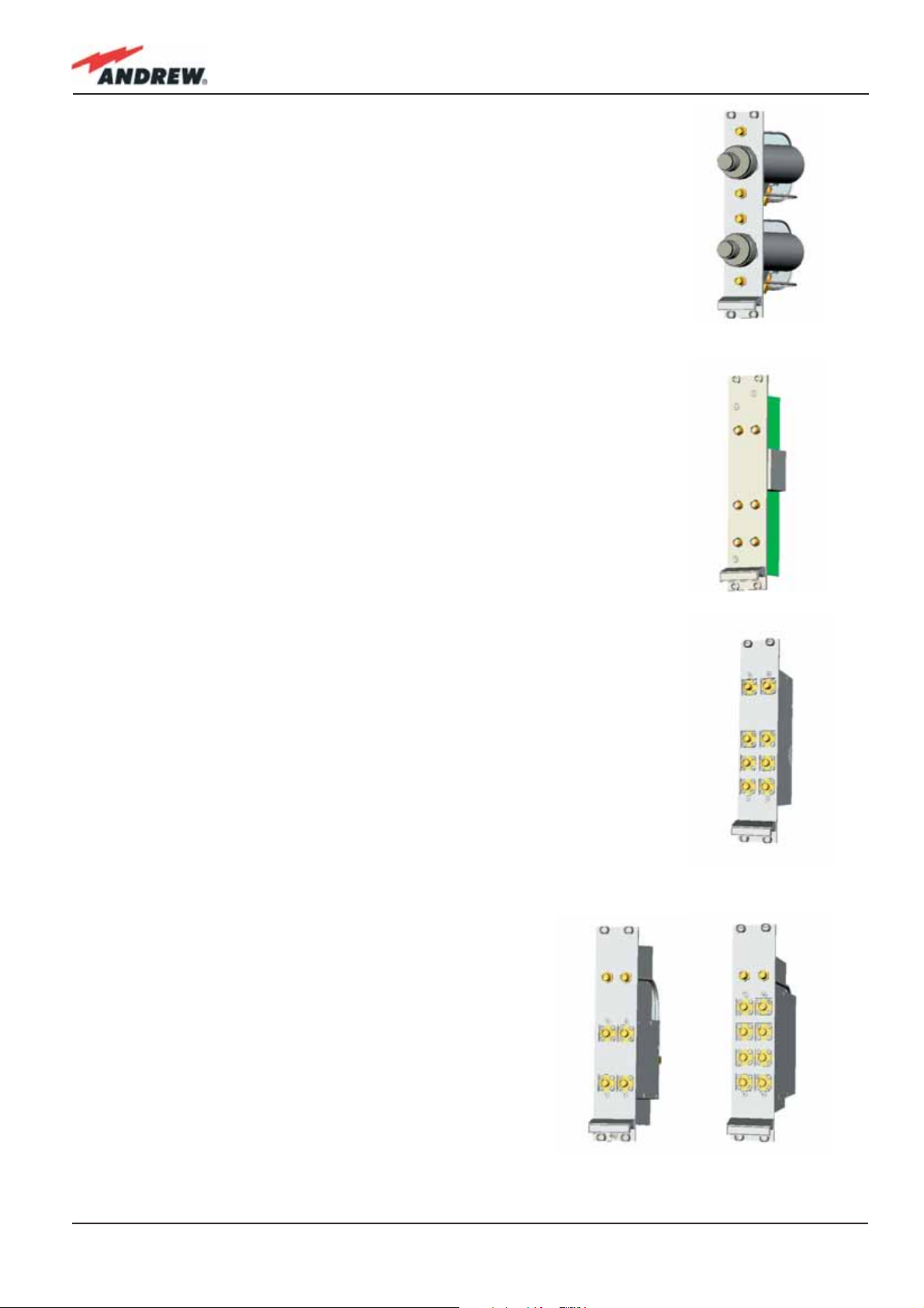
The variable RF attenuators (TBSI): they provide independent
attenuations (adjustable from 0 to 30dB, with 1dB steps) on uplink and
downlink RF paths, and allow the designer to optimize the signal level
close to the BTSs. TBSI is an override attenuator, its dimensions are: Width =
7TE, Height = 4HE.
Fig. 2.7 TBSI card
The Dual Band Coupler (TLDN): in downlink, it combines a low band RF
signal (800 to 1000 MHz) and a high band RF signal (1700 to 2500 MHz) into
a common RF port; in uplink, it splits a composite signal between a low
band RF port and a high band RF port. Module dimensions are: Width = 7
TE, Height = 4 HE.
Fig. 2.8 TLDN card
The Tri Band Coupler (TLTN): in downlink, it combines a Low Band signal, a
Middle Band signal, and a High Band signal into a communal one; in uplink,
it splits the triple band signal among the three RF single band paths.
Please refer to table 4.7.1 or to the bulletin PA-100596-EN for further
information about the different band confi gurations.
Module dimensions are: Width = 7 TE, Height = 4 HE.
Fig. 2.9 TLTN card
The RF splitters/combiners (TLCN2 and TLCN4): TLCN2
is a 2-way splitter/combiner. TLCN4 is a 4-way splitter/
combiner. They can be used in a variety of different
situations, such as:
• To connect a BTS with several master optical TRXs.
In uplink, the TLCN2 (or TLCN4) combines 2 (or 4) RF
signals which come from different master optical
TRXs into a common RF signal entering the BTS. In
downlink, the TLCN2 (or TLCN4) splits the downlink
composite RF signal which comes from the BTS into 2
(or 4) RF ports, entering different master optical TRXs.
20
(a) (b)
Fig. 2.10 TLCN2 (a) and TLCN4 (b) cards
ION-B User Manual
• To connect several BTSs to a master optical TRX. In downlink, the TLCN2 (or TLCN4)
combines the RF signals coming from different BTSs into a common RF signal, entering the
master optical TRX. In uplink, the TLCN2 (or TLCN4) splits the composite RF signal coming from a
master optical TRX into 2 (or 4) RF signals entering different BTSs.
The Power Limiter (TMPx-10): it monitors the DL power coming from the
BTS and attenuates it by 10 dB in case it surpasses a programmable
threshold level.
The TMP2-10 Power Limiter is for 2G and 2.5G signals, working at 900
MHz and 1800 MHz.
The TMP3-10 Power Limiter is for 3G signals.
Both modules are 7TE wide and 4HE high.
Fig. 2.11 TMPx-10 card
Table 2.2 shows an overview of the basic
components of the ION-B Master Unit.
Basic components of ION-B Master Units
Unit name/
Module name
TPRF31
TPRN04
TPRNx4
TFLNx
TLCN 2
TLCN 4
TBSI 2-30
TDPNx
Description Dimensions, H x W ( x D)
Fast MiniRack
Passive subrack
Active subrack
Master Optical TRX
2-way splitter
4-way splitter
Adjustable attenuator
UL/DL duplexer
19” x 1HE x 286mm
19” x 4HE x 350mm
19” x 4HE
7TE x 4HE
7TE x 4HE
7TE x 4HE
7TE x 4HE
7TE x 4HE
TLDNx
TLTNx
TMPx-10
Table 2.2: Overview of the components and accessories for the ION-B master unit
Dual band coupler
Tri band coupler
10 dB power limiter
7TE x 4HE
7TE x 4HE
7TE x 4HE
21MN024-010
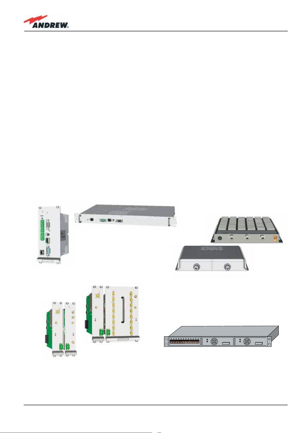
2.4. ION-B additional options
The basic ION-B structure described above can be furtherly expanded or supported by a
range of ION-B options, including:
• A supervision unit (TSUN), enabling to supervise and manage the ION-B system through
any PC or Laptop, thanks to a web-interface supporting the TCP/IP, FTP, HTTP, protocols,
and fully compatible with general purpose SNMP managers.
• RF boosters, which can be connected to the auxiliary channels of the ION-B Remote
Units, thus providing RF coverage in some particular frequency bands (e.g. AWS 1700 MHz
in US, Wi-Fi, or Wi-Max);
• A wide range of Interconnect Link options (TIL), i.e. a set of master-slave modules which
enable to expand the ION-B system through additional subrack stations, up to 20 km
away from the main one.
• A Remote Powering Unit (TRSN), providing -48Vdc power supplying through composite
fi beroptic/copper cables
Table 2.3 shows an overview of these ION-B accessories and of the corresponding Andrew
bulletins you should refer to for further information.
(a)
(e)
(f)
(b)
(d)
(c)
(g)
22
Fig. 2.12: TSUN supervision unit, available both as a plug-in card (a) and as a stand-alone module (b) ;
Wi-Fi (c) and (AWS 1700 MHz) boosters; Interconnect-link master modules (e) and slave modules (f);
TRSN Remote Powering units (g)
ION-B User Manual

Although the following table tables show a brief overview of the main ION-B additional
options, we strongly recommend you to contact your reference Andrew Salesperson or
Product Line Manager in order to have For a full overview of the ION-B options,
Main ION-B additional options
Unit name/
Module name
ION-B Supervision Unit
(TSUN 1, 3, 6)
ION-B Wi-Fi options
TIL Interconnect link
RF dedicated booster
TRSN Remote Power Units
Table 2.3: Overview of the components and accessories for the ION-B rack-based master unit
Reference Bulletin Reference Manual
PA-100596-EN
PA-100928-EN
BR-102130-EN
PA-102073-EN
PA-102072-EN
MN023
MN031
MN032
MN033
Mechanical
Decription
Available both as a plug-in card
and as a stand-alone unit
Different solutions available
multi-module master side
+ multi-module slave side
(each one made of a variable
number of plug-in cards)
stand alone unit,
240 x 200 x 38 mm
19” x 3HE (low power version)
19” x 1HE (medium power
version)
23MN024-010
2.5. Block Diagrams
In order to better understand the functionalities of the different units and modules, some block
diagrams of the ION-B system are presented here.
The core of an ION-B system is the ION-B master unit, which generally develops through a
passive section (providing Level adjustments, Signal splitting/combining, and Band coupling),
followed by an Electrical/Optical conversion (allowing the signal to be distributed through
fi beroptic cables to the TFAx Remote Units).
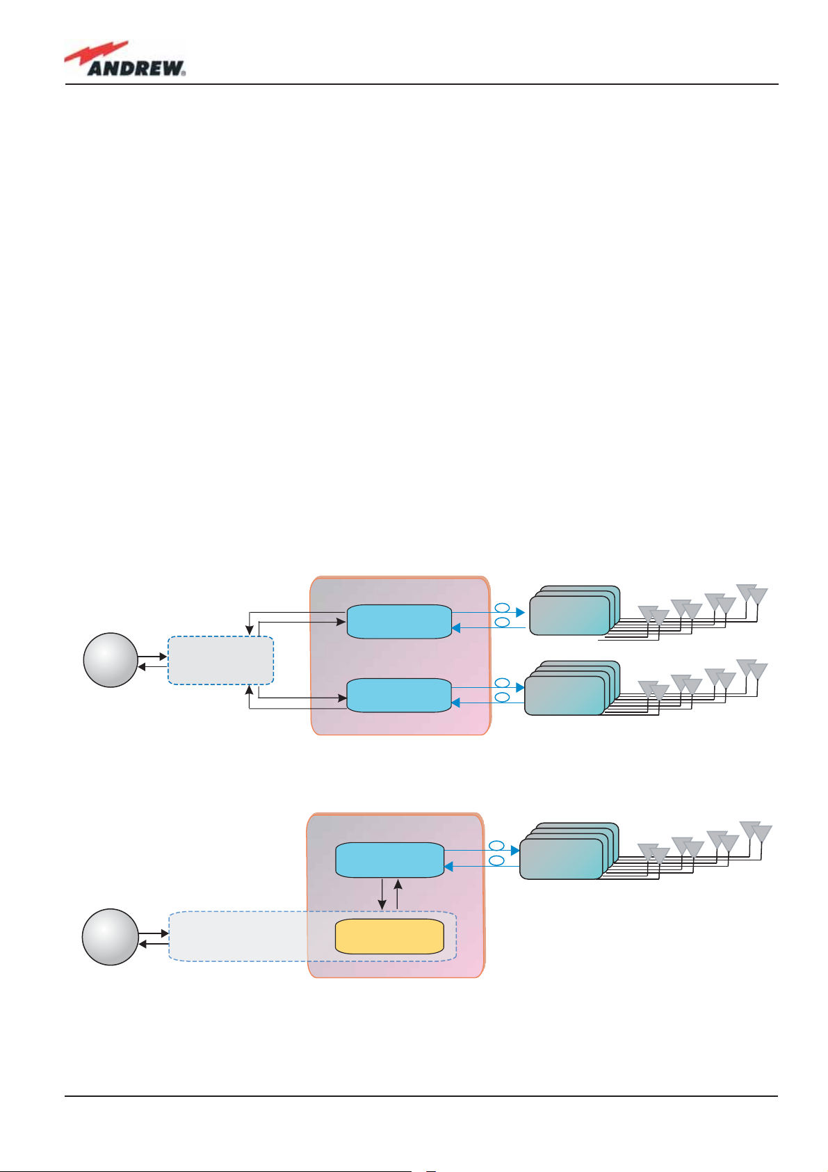
Simple and unobstrusive ION-B installations can be developed through the TPRF31 fast
MiniRacks, which allows a great deal of installation solutions, such as:
- hosting two electrical/optical transceivers, while developing external passive combining
- hosting one electrical/optical transceiver, plus one ION-B interface card (providing splitting/
combining , band coupling or level adjusting).
Please note that more TPRF31 modules can be combined to achieve a more complex, spacesaving system confi guration.
Tipical ION-B confi gurations based on a single TPRF31 Fast MiniRack are shown in fi g. 2-13.
BTS
BTS
External
splitting/combining
section
Splitting/combining section
ION-B Fast Minirack
TFLN
Master Optical Trx
+
TFLN
Master Optical Trx
(a)
ION-B Fast Minirack
TFLN
Master Optical Trx
ION-B passive card
(either splitting/combining
or level adjusting
Remote Unit
TFAx
Remote Unit
TFAx
Remote Unit
TFAx
24
(b)
Fig. 2.13: ION-B confi gurations based on a TPRF31 Fast MiniRack: (a) Confi guration hosting 2 TFLN optical
transceivers; (b) Confi guration hosting 1 TFLN optical transceiver and 1 splitting/combining card
ION-B User Manual

Although TPRF31 proves to be very fl exible, complex distribution systems usually can be better
served by rack-based ION-B Master Units: such ION-B installations are based on one or more
TPRN-subracks, thus exploiting the wide range of ION-B passive cards (TDPN, TMP, TBSI, TLCN2,
TLCN4, TLTN, TLDN), in order to build the passive network which best matches the costumer’s
needs.
Let’s see some examples of such rack-based confi gurations.
Firstly, assume that the BTSs are not duplexed. In this case, no TDPN module (see fi g. 2.14)
is required. Moreover, assuming that the Master Unit is made up of one or more subracks
located in a single site, we do not need an interconnect link in order to remotise a second
subrack. The scheme of this network confi guration is reported hereafter in fi gure 2.14.
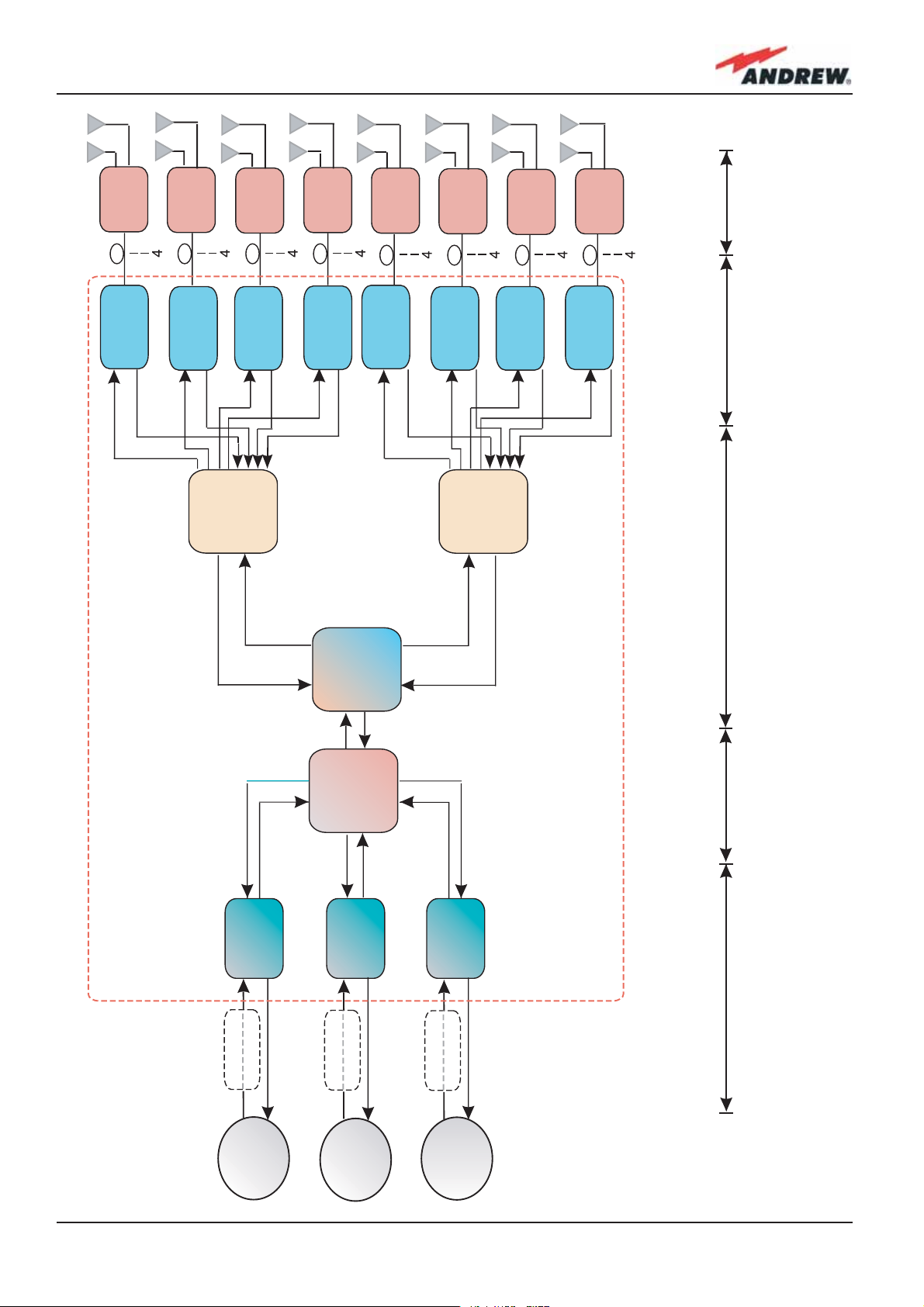
Now let’s consider the same network confi guration, but with duplexed BTSs. In this case, some
TDPN modules (see fi g. 2.7) are required in order to combine UL and DL ports on single RF
channels. The scheme of this network confi guration is reported hereafter in fi gure 2.15.
If we need to expand our ION-B network to a wider area, please note that the Interconnectlink option allows you to use a second subrack station at a distance of up to 20km from the
site where the main subrack station is located.
Please refer to the dedicated Interconnect link brochure (Table 2.3) for further details.
25MN024-010

Frequency
Band 3
BTS
Frequency
Band 2
BTS
Frequency
Band 1
BTS
Fig. 2.14: Block diagram of an
ION-B confi guration supporting
a triple-band system with
DUPLEXED base stations.
,EVELADJUSTMENT
COMBINING
SPLITTING
3ERVICE
Master Unit
Attenuator
Fixed
Duplexer
TDPN
Attenuator
TBSI
Attenuator
Fixed
Duplexer
TDPN
Attenuator
TBSI
Multi-band
Combiner
TLTN
Attenuator
Fixed
Duplexer
TDPN
Attenuator
TBSI
COMBINING
SPLITTING
3IGNAL
%LECTRICAL/PTICAL
CONVERSION
/PTICAL%LECTRICAL
CONVERSION
Optical Trx
Master
TFLN
Remote Units
REMOTE
TFAx
UNIT
Optical Trx
REMOTE
UNIT
Combiner
Master
TFLN
TFAx
Splitter/
TLCN4
Optical Trx
Master
REMOTE
UNIT
TFAx
TFLN
Optical Trx
REMOTE
UNIT
Combiner
Splitter/
Master
TFLN
TFAx
TLCN2
Optical Trx
Master
REMOTE
UNIT
TFLN
TFAx
Optical Trx
Master
REMOTE
UNIT
Combiner
Splitter/
TLCN4
Optical Trx
TFLN
TFAx
UNIT
Master
TFLN
REMOTE
TFAx
Optical Trx
Master
REMOTE
UNIT
TFLN
TFAx
26
ION-B User Manual
TFAx
REMOTE
UNIT
TFAx
REMOTE
UNIT
TFAx
REMOTE
UNIT
TFAx
REMOTE
UNIT
TFAx
REMOTE
UNIT
TFAx
REMOTE
UNIT
TFAx
REMOTE
UNIT
TFAx
REMOTE
UNIT
Remote Units
CONVERSION
/PTICAL%LECTRICAL
TFLN
Master
Master
Optical Trx
TFLN
Master
TFLN
Optical Trx
Master
TFLN
Optical Trx
Master
TFLN
Master
Optical Trx
Optical Trx
CONVERSION
TFLN
Optical Trx
Master
TFLN
Optical Trx
Master
TFLN
Optical Trx
%LECTRICAL/PTICAL
TLCN4
Splitter/
Combiner
TLCN2
Splitter/
Combiner
TLCN4
Splitter/
Combiner
3IGNAL
COMBINING
SPLITTING
Master Unit
TBSI
Attenuator
Fixed
Attenuator
BTS
Band 1
Frequency
TLTN
Combiner
Multi-band
TBSI
Attenuator
Fixed
Attenuator
BTS
Band 2
Frequency
TBSI
Attenuator
Fixed
Attenuator
BTS
Band 3
Frequency
3ERVICE
COMBINING
,EVELADJUSTMENT
Fig. 2.15: Block diagram of an
ION-B confi guration supporting
a triple-band system with NOT
DUPLEXED base stations.
SPLITTING
27MN024-010

28
ION-B User Manual

3. TFAx Remote Unit
29MN024-010
3.1. Introduction
The Main Tasks of the TFAx Unit:
Downlink (DL):
• Optical-to-RF conversion of the input optical signal
• Automatic Gain Control (AGC) of each converted signal, in order to compensate optical
losses;
• RF amplifi cation: the converted RF signal is boosted in order to maintain a good signal-tonoise ratio
• RF fi ltering: a proper fi lter rejects the spurious emissions
• RF duplexing and splitting: the boosted RF signal is conveyed to 2 antenna ports
Uplink (UL):
(b)
(a)
(d) (e)
Fig. 3.1.1: ION-B Remote Units: different cases for different solutions
(c)
• RF amplifi cation: a low noise amplifi er boosts the signal received from antennas in order
to maintain a good signal-to-noise ratio
• RF fi ltering: the boosted signal is cleaned of the spurious emissions
30
ION-B User Manual

• Automatic Level Control (ALC): the RF signal level is adjusted according to blocking
requirements
• RF-to-optical conversion of the signal, which is fi nally conveyed to the output optical port
Different Types of Remote Units
In order to allow radio coverage with different power and band requirements, the ION-B
architecture provides a wide variety of Remote Units. This allows the customer to choose the
solution which best fi ts its coverage and environmental demands.
Depending on the bands where the radio coverage has to be provided and on the signal
power required to cover the environment, your Remote Unit will fall into one of the topologies
shown in fi gure 3.1.1.
The following 4 sections of the manual refer to these 4 Remote Unit topologies. Please follow
the instructions described in the section corresponding to the case (A, B, R, R2, F) of your
particular Remote Unit.
The case of your Remote Unit can be easily identifi ed in Figure 3.1: or, as an alternative, you
could contact your Sales representative or check it on the offi cial ION-B Brochure (see fi g.
3.1.2),.
As in fi g. 3.1.2, the “TFAM 91/18/20” Remote Unit proves to be described in the Andrew bulletin
PA-100508-EN. Look through the Remote Unit’s dedicated bulletin in order to get all of the
technical specifi cations concerning the unit itself.
Remote UnitS
Power Class*, dBm Case Product Code Bulletin Code
GSM900 EGSM900 GSM1800 UMTS2100 LMR800 Cellular850 LMR900 AWS1700 PCS1900 PCS1900 Ext.
27 - - 27 - - - - - - B TFAM 90/20 PA-100582-EN
- 27 - 27 - - - - - - B TFAM 91/20 PA-100583-EN
- - 27 27 - - - - - - B TFAM 18/20 PA-100584-EN
- 32 32 36 - - - - - - R2 TFAM91/18/20 PA-101508-EN
- - - - 27 - - - 27 - B TFAM 80/19 PA-100801-EN
- - - - - 27 - - 27 - B TFAM 85/19 PA-100805-EN
- - - - - - - 27 27 - B TFAM 17/19 PA-101848-EN
- - 27 - - 27 - - - - B TFAM 85/18 PA-100808-EN
- - - 27 - 27 - - - - B TFAM85/20 PA-100809-EN
- - - - 21 - 21 - - 27 B TFAM80/92/19E PA-101058-EN
Fig. 3.1.2: Remote Unit description in the offi cial ION-B Brochure (Rev. 03/07)
31MN024-010

TFAM
Case A
32
ION-B User Manual

3.3. Case A Remote Unit
Dimensions and Weight:
Dimensions: 38 x 240 x 200 mm
(1.5 x 9.4 x 7.9 inches)
Weight : please refer to the Remote Unit dedicated bulletin in order to discover any
updated data regarding the weight of the case A Remote Unit
LED alerts
Green =power ON;
Red = major alarm
TFAM
Case A
Power
supply
connector
RF auxiliary
DL channel
output
RF
antenna
port
DL
optical
port
Fig. 3.2.1: TFAx Case A Remote Unit
UL
optical
port
RF
antenna
port
RF auxiliary
UL channel
input
External
alarm
connection
RF ports:
• 2 RF antenna ports, transmitting/receiving signals to/from distributed antennas. RF
antenna ports are duplexed N-female connectors. These RF ports can be connected
to the antennas either directly (ie. through RF jumper cables) or through splitters, thus
allowing more antennas to be fed. Unused RF ports have to be terminated with a 50 Ω
load.
• 1 RF auxiliary input and 1 auxiliary output (designed to receive and transmit additional
signals). Auxiliary input and output ports are SMA-female connectors.
Optical ports:
• 1 optical output port, transmitting UL signals to TFLN master optical TRX
• 1 optical input port, receiving DL signals from TFLN master optical TRX
33MN024-010

Visual Alarms:
TFAM
Case A
Two control LEDs are provided on the TFAx front side (Fig. 3.2.2). The green LED indicates the
power supply status, while the red LED indicates any major Remote Unit failures (please refer to
Table 3.4).
Led colour Meaning
Low optical power at DL input
and/or RF amplifi er failure
of Case-A remote unts
Figure 3.2.2 - LED alarms on
the upper-front side of Case
B Remote Units (including Power version)
Red
Green Power supply OK
Table 3.2.1 - Description of the LEDs
Dry Contact Alarms:
TFAx is provided with two dry contact inputs which
can be connected (through .062” MOLEX plugs)
to any external device. The alarm information
regarding this external device is able to be
signalled through the red LED of the TFAx LED panel
and displayed on the Supervision System in this
Figure 3.2.3:
Dry contacts for external alarms
way.
Power Supply
The Case A Remote Unit is provided with a TPSN external power supply (Fig. 3.2.4 a,b),
available either for universal mains (90 to 264) or for negative supply. (-72 to -36 Vdc).
(b)
34
(c)
(a)
Figure 3.2.4 - The Case-A power supply inlet (a) can
be connected either with the ION-B 220Vac power
adapter (b) or with the -48 Vdc one ( c), depending
on the chosen version.
ION-B User Manual

TPSN external power supplies provide the Case A Remote Unit with +5Vdc power, by means of
a 3-pole connector.
Warnings (to be read before Remote Units are installed)
Dealing with optical output ports
The TFAx Remote Unit contains semiconductor lasers. Invisible laser beams may be emitted
from the optical output ports. Do not look towards the optical ports while equipment is
switched on.
Choosing a proper installation site for the Remote Units
• TFAx Remote Units have to be installed as close as possible to the radiating antennas,
in order to minimize coaxial cable length, thus reducing downlink power loss and uplink
noise fi gures.
• When positioning the TFAx Remote Unit, be sure to place related antennas in such a way
as to minimize the Minimum Coupling Loss (MLC), in order to avoid blocking.
• The TFAx Remote Unit is intended to be fi xed on walls, false ceilings or other fl at vertical
TFAM
Case A
surfaces (TKA installation kits are available, they provide a protective cover for the TFAx
Remote Unit, while making installation easier and faster).
Handling optical connections
• When inserting an optical connector, take care to handle it so that the optical fi bre is not
damaged. Optical fi bres are to be in single-mode (SM) 9.5/125µm.
• Typically, ION-B equipment is provided with SC-APC optical connectors (other connectors
are provided upon request). Inserting any other connectors will result in severe damage.
• Do not force or stretch the fi bre pigtail with curvature radius of less than 5cm. See fi gure
on right for optimal fi bre cabling.
• Remove the adapter caps only just before making connections. Do not leave any SC-
WRONG
Figure 3.2.5 - Handling
optical connections with
ION-B Remote Units.
CORRECT
35MN024-010

APC adapters open, as they attract dirt. Unused optical connectors must always be
TFAM
Case A
covered with their caps.
• Do not touch the connector tip. Clean it with suitable material before inserting each
connector into its sleeve. If connector tips require cleaning, use only pure ethyl alcohol.
TFAx Case A installation
The Case B Remote Unit is able to be fi xed to walls, false ceilings or other fl at vertical surfaces,
either directly or through a TKA04 installation kit (optional).
Installing a Case A Remote Unit WITHOUT the TKA kit
The TFAx kit includes:
1. a Remote Unit TFAx
2. a TPSN external power supply adapter (86 to 264 Vac or -72 to -36 Vdc, according to the
chosen model)
3. a VDE connector or a -48 Vdc plug (according to the chosen model)
The TKA04 kit includes:
A. four screw anchors (fi xing the wall bearing to the wall)
B. fi ve screw anchors (fi xing the TFAx Case A to the wall bearing)
C. a wall mounting box (wall bearing + cover)
D. a splice holder
Please consider these guidelines in order to choose the correct positioning of the Remote Unit
and of its power supply:
• Under no circumstances should any piece of equipment be affected by the heat
(a)
Figure 3.2.6: Example of proper mounting confi guration, which assures proper heat dissipation. Note that the
Remote Unit and its power supply adapter are mounted side-by-side, and the power supply adapter has the
socket downwards. The Figures refer to a 90/264 vac TFAx Case A (an) and to a -36/-72 Vdc TFAx Case A (b).
36
(b)
ION-B User Manual

created by any other piece. The Remote Unit and its external power supply should be
mounted so as to avoid reciprocal heating. Side-by-side confi guration is suggested (Fig.
3.2.6 a,b)
• Remote Units are provided with cooling fi ns which allow the optimization of heat
dissipation. In order for them to function properly, the mounting environment should allow
for the necessary air changeover
• It is strongly recommended not to mount the external power supply on a horizontal
surface because this position does not allow heat dissipation. External power supplies
must be mounted on vertical surfaces.
• In order to assure proper heat dissipation, external power supplies must be mounted in a
vertical position with the power socket downwards (see Fig. 3.2.7 a,b).
Once you have chosen a location for the Remote Unit, please follow these instructions:
1. In order to install the M4 screw anchors (not included) which hold up the TFAx Remote
Unit, drill into the wall according to the proper layout shown in Fig. 3.2.9.
2. Fix the TFAx to the wall by fi rmly tightening the screws into the anchors.
3. In order to install the M4 screw anchors (not included) which hold up the power supply
TFAM
Case A
SPLICE HOLDER
(a)
Fig. 3.2.7. (a) inside of the Splice Tray, with the Splice
Holder positioned properly; closed splice tray (b)
(b)
external adapter, drill into the wall according to the proper layout of your power supply,
shown in fi g.3.3.10b
4. Fix the external power supply adapter to the wall by fi rmly tightening the screw into the
anchors.
5. Fix the splice holder inside the splice tray (not included) See Fig. 3.2.7 a,b.
6. Splice the optical fi bres and close the splice tray. While handling the fi bers, be careful not
to bend them.
7. Fix the splice tray beside the Remote Unit.
8. Connect the external adapter to the TFAx Remote Unit with the proper cable.
9. If the Remote Unit is -48 Vdc powered, use the -48 Vdc plug (included) in order to
37MN024-010

connect the external adapter to the -48 Vdc supply (Fig. 3.2.6 b). If the Remote Unit
TFAM
Case A
is 90/264 Vac-powered, fi x the 90/264 Vac plug (included) onto a power cord (not
included), and use this cable to connect the external adapter to the mains (Fig. 3.2.6 a).
10. Connect the antenna RF cables to the RF antenna ports. Connect the UL and DL optical
connectors.
11. Once the installation is fi nished, please follow the section “TFAx Case A Start-up” in order
to carry out a proper system start up.
Installation of the Case A Remote Unit WITH the TKA04 installation kit
The TFAx Case A kit includes:
1. a Remote Unit TFAx
2. a 50 Ω load
3. a TPSN external power supply adapter (86 to 264 Vac or -72 to -36 Vdc, according to the
chosen model)
4. a VDE connector or a -48 Vdc plug (according to the chosen model)
The TKA04 kit includes:
A. four screw anchors (fi xing the wall bearing to the wall)
B. fi ve screw anchors (fi xing the TFAx Case A to the wall bearing)
C. a wall mounting box (wall bearing + cover)
D. a splice holder
Please consider these guidelines carefully in order to decide the proper positioning of the
(a)
(b)
Figure 3.2.8:
Example of proper mounting confi guration, which assures proper heat dissipation. Note that the Remote Unit and
its power supply adapter are mounted side-by-side, and the power supply adapter has the socket downwards.
The Figures refer to a 90/264 vac TFAx Case A (a) and to a -36/-72 Vdc TFAx Case A (b), respectively.
38
ION-B User Manual

Remote Unit and its power supply:
• Under no circumstances should any piece of equipment be affected by the heat
created by any other piece. The Remote Unit and its external power supply should be
mounted so as to avoid reciprocal heating. Side-by-side confi guration is suggested (Fig.
3.2.8 a,b)
• It is strongly recommended not to mount the external power supply on a horizontal
surface because this position does not allow for heat dissipation. External power supplies
must be mounted on vertical surfaces.
• In order to assure proper heat dissipation, the external power supplies must be mounted
in a vertical position with the power socket downwards (see Fig. 3.2.8 a,b).
Once you have chosen the position of the Remote Unit mounting case, please follow these
instructions:
1. Unscrew the 4 screws which lock the lower cover of the TKA04 wall bearing (see Fig.
3.2.12 a)
2. In order to install the M4 screw anchors (included) which hold up the TKA04 wall bearing,
drill into the wall according to the TKA layout shown in Fig. 3.2.11.
3. Fix the TKA04 wall bearing by fi rmly tightening the screws into the anchors.
TFAM
Case A
4. In order to install the M4 screw anchors (not included) which hold up the power supply
external adapter, drill into the wall according to the power supply layout shown in
Fig.3.3.10 b.
5. Fix the external power supply adapter to the wall by fi rmly tightening the screws into the
anchors (Fig. 3.2.13 b).
6. Carefully open the splice tray by using a screwdriver as in Fig. 3.2.12 c. Fix the splice
holder inside the splice tray (Fig. 3.2.6 a). Splice the optical fi bres and close the splice
tray. While handling the fi bers, take care not to bend them. Close the splice tray.
7. Fix the Remote Unit to the wall-bearing by using the included screws (Fig. 3.2.6 b).
8. If the Remote Unit is -48 Vdc powered, use the -48 Vdc plug (included) in order to
connect the external adapter to the -48 Vdc mains (Fig. 3.2.8 b). If the Remote Unit
is 90/264 Vac-powered, fi x the 90/264 Vac plug (included) onto a power cord (not
included), and use this cable in order to connect the external adapter to the mains (Fig.
3.2.8 a).
9. Connect the antenna RF cables to the RF antenna ports. Connect the UL and DL optical
connectors (Fig. 3.2.12 e). If the power cable has properly been connected to the
mains, both the green and the red LEDs should turn on. The green LED will remain lit to
indicate that the unit is powered on, while the red LED will turn off as soon as the local
unit is switched on (for further details about the start up of the system, please refer to the
section “TFAx Case A Start-up”)
10. Fix the lower cover by fastening the 4 screws (Fig. 3.2.12 f)
39MN024-010

TFAM
Case A
40
Figure 3.2.9 : Case A layout with waal anchor quotes
ION-B User Manual

TFAM
Case A
X
Figure 3.2.10:
Layout of the 220Vac/+5Vdc power adapter,
provided with Case A Remote Units.
41MN024-010

TFAM
Case A
42
Figure 3.2.11: Layout of the TKA installation kit for TFAx Remote Unit, Case A.
ION-B User Manual

(a) (b)
TFAM
Case A
(c)
(e)
Figure 3.2.12: Mounting the TFAx Case A Remote Unit with a TKA installation kit.
Please not that the Figures do not show the mounting of the external power supply.adapter.
(d)
(f)
43MN024-010

TFAx Case A Start-Up
Before the TFAx Remote Unit is switched on, make sure that:
• the modules hosted in the master unit have been connected to each other with RF
jumpers, according to the system design
• every TFLN master optical TRX has been connected to its Remote Units
• each Remote Unit has been connected to its coverage antennas
For a correct system start-up, all the Remote Units have to be switched on prior to the master
unit.
Once the TFAx has been switched on, its behaviour can be summarized as per the following
indicators:
1. When the Remote Unit is turned on, both the LEDs upon the warm side turn on for a
couple of seconds
2. After that, the unit’s green LED remains on (thus indicating proper power supply), while
the red LED switches off as soon as the master unit is turned on (meaning that DL optical
power is OK and no alarms are present).
3. Once the master unit has been switched on, the status of both LEDs should be
those indicated in Table 3.2.1. In case the red LED remains on, please refer to the
Troubleshooting section.
4. After being switched on, the Remote Unit should start up correctly and in order to be
recognized by the supervision management system, the corresponding TFLN master
optical TRX should carry out the discovery phase (please refer to the Supervision System
Manual for more details). During this phase, which can last for up to a max. 4min,
depending on the system complexity, the TFLN LED
any cables or pieces of equipment during the discovery phase! This may result in the
identifi cation failure of the Remote Unit.
Note: in case discovery doesn’t start automatically, check through either the LMT or the
remote supervision for whether it has been disabled (refer to LMT or remote Supervision System
manuals for further information).
blinks. Do not connect/disconnect
TFAx Case A Troubleshooting
Please refer to the TFAx Case A and Case B troubleshooting for a full overview of the
troubleshooting procedures for Case A Remote Units.
44
ION-B User Manual

3.4. Case B Remote Unit
Dimensions and Weight:
Dimensions: 38 x 240 x 240 mm
(1.5 x 9.4 x 9.4 inches)
Weight : please refer to the Remote Unit dedicated bulletin in order to discover any
updated data regarding the weight of the Case B Remote Unit
LED alerts
Green =power ON;
Red = major alarm
(a)
TFAM
Case B
Power
supply
connector
LED alerts
Green =power ON;
Red = major alarm
Power
supply
connector
RF auxiliary
DL channel
output
RF auxiliary
DL channel
input
RF
antenna
port
RF
antenna
port
DL
optical
port
DL
optical
port
UL
optical
port
UL
optical
port
RF
antenna
port
RF
antenna
port
RF auxiliary
UL channel
input
RF auxiliary
UL channel
input
External
alarm
connection
(b)
External
alarm
connection
Fig. 3.3.1: TFAx Case B Remote Unit (a) and TFAx Case B Remote Unit, Power version (b)
45MN024-010

RF ports:
• 2 RF antenna ports, transmitting/receiving signals to/from distributed antennas. RF
antenna ports are duplexed N-female connectors. These RF ports can be connected
TFAM
Case B
to the antennas either directly (ie. through RF jumper cables) or through splitters, thus
allowing more antennas to be fed. Unused RF ports have to be terminated with a 50 Ω
load.
• 1 RF auxiliary input and 1 auxiliary output (designed to receive and transmit additional
signals). Auxiliary input and output ports are SMA-female connectors.
Optical ports:
• 1 optical output port, transmitting UL signals to TFLN master optical TRX
• 1 optical input port, receiving DL signals from TFLN master optical TRX
Visual Alarms:
Two control LEDs are provided on the TFAx front side (Fig. 3.3.2). The green LED indicates the
power supply status, while the red LED indicates any major Remote Unit failures (please refer to
Table 3.4).
Led colour Meaning
Low optical power at DL input
and/or RF amplifi er failure
of Case-B remote unts
Figure 3.3.2 - LED alarms on
the upper-front side of Case
B Remote Units (including Power version)
Red
Green Power supply OK
Table 3.3.1 - Description of the LEDs
Dry Contact Alarms:
TFAx is provided with two dry contact inputs which
can be connected (through .062” MOLEX plugs)
to any external device. The alarm information
regarding this external device is able to be signalled
through the red LED of the TFAx LED panel and
displayed on the Supervision System in this way.
Figure 3.3.3 - Dry contacts for external alarms on (a)
Case B Remote Unit and (b) case-B Power Remote
Unit
46
(a)
(b)
ION-B User Manual

Power Supply
The Case B and Case B, Power version Remote Units are provided with different types of TPSN
external power supplies (Fig. 3.3.4 a,b), available either for universal mains (90 to 264) or for
negative supply. (-72 to -36 Vdc).
TPSN external power supplies for
Case-B Remote Units provide the with +5Vdc power, by
means of a 3-pole connector (Fig. 3.20 c).
TPSN external power supplies for
Case-B, Power version Remote Units provide the with +28Vdc
power, by means of a shielded circular connector (Fig. 3.20 c).
Before installing your Remote Unit, please check you have been provided with the proper
external power supply. Should you have any doubt, please contact your Sales representative.
(b)
TFAM
Case B
(c)
(a)
Figure 3.3.4 - The Case-B power supply inlet (a) can
be connected either with the ION-B 220Vac power
adapter (b) or with the -48 Vdc one ( c), depending
on the chosen version.
Likewise, the Case-B Power version (d) can be
connected either to the ION-B 220Vac power
adapter or to the -48Vdc one (e).
(e)
(d)
47MN024-010

TFAM
Case B
Warnings (to be read before Remote Units are installed)
Dealing with optical output ports
The TFAx Remote Unit contains semiconductor lasers. Invisible laser beams may be emitted
from the optical output ports. Do not look towards the optical ports while equipment is
switched on.
Choosing a proper installation site for the Remote Units
• TFAx Remote Units have to be installed as close as possible to the radiating antennas,
in order to minimize coaxial cable length, thus reducing downlink power loss and uplink
noise fi gures.
• When positioning the TFAx Remote Unit, be sure to place related antennas in such a way
as to minimize the Minimum Coupling Loss (MLC), in order to avoid blocking.
• The TFAx Remote Unit is intended to be fi xed on walls, false ceilings or other fl at vertical
surfaces (TKA installation kits are available, they provide a protective cover for the TFAx
Remote Unit, while making installation easier and faster).
Handling optical connections
• When inserting an optical connector, take care to handle it so that the optical fi bre is not
damaged. Optical fi bres are to be in single-mode (SM) 9.5/125µm.
• Typically, ION-B equipment is provided with SC-APC optical connectors (other connectors
are provided upon request). Inserting any other connectors will result in severe damage.
• Do not force or stretch the fi bre pigtail with curvature radius of less than 5cm. See fi gure
on right for optimal fi bre cabling.
• Remove the adapter caps only just before making connections. Do not leave any SCAPC adapters open, as they attract dirt. Unused optical connectors must always be
covered with their caps.
48
WRONG
Figure 3.3.5 - Handling optical
connections with ION-B Remote Units.
CORRECT
ION-B User Manual

• Do not touch the connector tip. Clean it with suitable material before inserting each
connector into its sleeve. If connector tips require cleaning, use only pure ethyl alcohol.
TFAx Case B installation
The Case B Remote Unit is able to be fi xed to walls, false ceilings or other fl at vertical surfaces,
either directly or through a TKA04 installation kit (optional).
Installing a Case B Remote Unit WITHOUT the TKA kit
The TFAx kit includes:
1. a Remote Unit TFAx
2. a TPSN external power supply adapter (86 to 264 Vac or -72 to -36 Vdc, according to the
chosen model)
3. a VDE connector or a -48 Vdc plug (according to the chosen model)
The TKA04 kit includes:
A. four screw anchors (fi xing the wall bearing to the wall)
B. fi ve screw anchors (fi xing the TFAx Case B to the wall bearing)
C. a wall mounting box (wall bearing + cover)
TFAM
Case B
D. a splice holder
Please consider these guidelines in order to choose the correct positioning of the Remote Unit
and of its power supply:
• Under no circumstances should any piece of equipment be affected by the heat
created by any other piece. The Remote Unit and its external power supply should be
mounted so as to avoid reciprocal heating. Side-by-side confi guration is suggested (Fig.
3.3.6 a,b)
(a)
(b)
Figure 3.3.6: Example of proper mounting confi guration, which assures proper heat dissipation. Note that the
Remote Unit and its power supply adapter are mounted side-by-side, and the power supply adapter has the
socket downwards. The Figures refer to a 90/264 vac TFAx Case B (an) and to a -36/-72 Vdc TFAx Case B (b).
49MN024-010

TFAM
Case B
• Remote Units are provided with cooling fi ns which allow the optimization of heat
dissipation. In order for them to function properly, the mounting environment should allow
for the necessary air changeover
• It is strongly recommended not to mount the external power supply on a horizontal
surface because this position does not allow heat dissipation. External power supplies
must be mounted on vertical surfaces.
• In order to assure proper heat dissipation, external power supplies must be mounted in a
vertical position with the power socket downwards (see Fig. 3.3.6 a,b).
Once you have chosen a location for the Remote Unit, please follow these instructions:
1. In order to install the M4 screw anchors (not included) which hold up the TFAx Remote
Unit, drill into the wall according to the proper layout shown in Fig. 3.3.9.
2. Fix the TFAx to the wall by fi rmly tightening the screws into the anchors.
3. In order to install the M4 screw anchors (not included) which hold up the power supply
external adapter, drill into the wall according to the proper layout of your power supply,
shown in fi g.3.4.10b
4. Fix the external power supply adapter to the wall by fi rmly tightening the screw into the
anchors.
5. Fix the splice holder inside the splice tray (not included) See Fig. 3.3.7 a,b.
6. Splice the optical fi bres and close the splice tray. While handling the fi bers, be careful not
to bend them.
7. Fix the splice tray beside the Remote Unit.
8. Connect the external adapter to the TFAx Remote Unit with the proper cable.
9. If the Remote Unit is -48 Vdc powered, use the -48 Vdc plug (included) in order to
connect the external adapter to the -48 Vdc supply (Fig. 3.3.6 b). If the Remote Unit
is 90/264 Vac-powered, fi x the 90/264 Vac plug (included) onto a power cord (not
included), and use this cable to connect the external adapter to the mains (Fig. 3.3.6 a).
10. Connect the antenna RF cables to the RF antenna ports. Connect the UL and DL optical
connectors.
11. Once the installation is fi nished, please follow the section “TFAx Case B Start-up” in order
to carry out a proper system start up.
SPLICE HOLDER
Fig. 3.3.7. (a) inside of the Splice Tray, with the Splice
Holder positioned properly; closed splice tray (b)
50
(a)
(b)
ION-B User Manual

Installation of the Case B Remote Unit WITH the TKA04 installation kit
The TFAx Case B kit includes:
1. a Remote Unit TFAx
2. a 50 Ω load
3. a TPSN external power supply adapter (86 to 264 Vac or -72 to -36 Vdc, according to the
chosen model)
4. a VDE connector or a -48 Vdc plug (according to the chosen model)
(a)
(b)
TFAM
Case B
Figure 3.3.8:
Example of proper mounting confi guration, which assures proper heat dissipation. Note that the Remote Unit and
its power supply adapter are mounted side-by-side, and the power supply adapter has the socket downwards.
The Figures refer to a 90/264 vac TFAx Case B (a) and to a -36/-72 Vdc TFAx Case B (b), respectively.
The TKA04 kit includes:
A. four screw anchors (fi xing the wall bearing to the wall)
B. fi ve screw anchors (fi xing the TFAx Case B to the wall bearing)
C. a wall mounting box (wall bearing + cover)
D. a splice holder
Please consider these guidelines carefully in order to decide the proper positioning of the
Remote Unit and its power supply:
• Under no circumstances should any piece of equipment be affected by the heat
created by any other piece. The Remote Unit and its external power supply should be
mounted so as to avoid reciprocal heating. Side-by-side confi guration is suggested (Fig.
3.3.8 a,b)
• It is strongly recommended not to mount the external power supply on a horizontal
surface because this position does not allow for heat dissipation. External power supplies
must be mounted on vertical surfaces.
• In order to assure proper heat dissipation, the external power supplies must be mounted
51MN024-010

TFAM
Case B
in a vertical position with the power socket downwards (see Fig. 3.3.8 a,b).
Once you have chosen the position of the Remote Unit mounting case, please follow these
instructions:
1. Unscrew the 4 screws which lock the lower cover of the TKA04 wall bearing (see Fig.
3.3.12 a)
2. In order to install the M4 screw anchors (included) which hold up the TKA04 wall bearing,
drill into the wall according to the TKA layout shown in Fig. 3.3.11.
3. Fix the TKA04 wall bearing by fi rmly tightening the screws into the anchors.
4. In order to install the M4 screw anchors (not included) which hold up the power supply
external adapter, drill into the wall according to the power supply layout shown in
Fig.3.4.10 b.
5. Fix the external power supply adapter to the wall by fi rmly tightening the screws into the
anchors (Fig. 3.2.13 b).
6. Carefully open the splice tray by using a screwdriver as in Fig. 3.3.12 c. Fix the splice
holder inside the splice tray (Fig. 3.3.6 a). Splice the optical fi bres and close the splice
tray. While handling the fi bers, take care not to bend them. Close the splice tray.
7. Fix the Remote Unit to the wall-bearing by using the included screws (Fig. 3.3.6 b).
8. If the Remote Unit is -48 Vdc powered, use the -48 Vdc plug (included) in order to
connect the external adapter to the -48 Vdc mains (Fig. 3.3.8 b). If the Remote Unit
is 90/264 Vac-powered, fi x the 90/264 Vac plug (included) onto a power cord (not
included), and use this cable in order to connect the external adapter to the mains (Fig.
3.3.8 a).
9. Connect the antenna RF cables to the RF antenna ports. Connect the UL and DL optical
connectors (Fig. 3.3.12 e). If the power cable has properly been connected to the
mains, both the green and the red LEDs should turn on. The green LED will remain lit to
indicate that the unit is powered on, while the red LED will turn off as soon as the local
unit is switched on (for further details about the start up of the system, please refer to the
section “TFAx Case B Start-up”)
10. Fix the lower cover by fastening the 4 screws (Fig. 3.3.12 f)
TFAx Case B Start-Up
Before the TFAx Remote Unit is switched on, make sure that:
• the modules hosted in the master unit have been connected to each other with RF
jumpers, according to the system design
• every TFLN master optical TRX has been connected to its Remote Units
• each Remote Unit has been connected to its coverage antennas
For a correct system start-up, all the Remote Units have to be switched on prior to the master
unit.
52
ION-B User Manual

TFAM
Case B
Figure 3.3.9 : Case B layout with wall anchor quotes
53MN024-010

TFAM
Case B
Figure 3.3.10:
(a) Layout of the 220Vac/+5Vdc power
adapter, provided with Case B Remote Units.
(b) Layout of the 220Vac/+5Vdc power
adapter, provided with Case B Remote Units.
(a)
X
(b)
54
X
ION-B User Manual

TFAM
Case B
Figure 3.3.11: Layout of the TKA installation kit, provided with Case B Remote Units.
55MN024-010

TFAM
Case B
(a) (b)
(c)
(e)
Figure 3.3.12: Mounting the TFAx Remote Unit with a TKA installation kit.
Please not that the Figures do not show the mounting of the external power supply.adapter.
(d)
(f)
56
ION-B User Manual

Once the TFAx has been switched on, its behaviour can be summarized as per the following
indicators:
1. When the Remote Unit is turned on, both the LEDs upon the warm side turn on for a
couple of seconds
2. After that, the unit’s green LED remains on (thus indicating proper power supply), while
the red LED switches off as soon as the master unit is turned on (meaning that DL optical
power is OK and no alarms are present).
3. Once the master unit has been switched on, the status of both LEDs should be
those indicated in Table 3.3.1. In case the red LED remains on, please refer to the
Troubleshooting section.
4. After being switched on, the Remote Unit should start up correctly and in order to be
recognized by the supervision management system, the corresponding TFLN master
optical TRX should carry out the discovery phase (please refer to the Supervision System
Manual for more details). During this phase, which can last for up to a max. 4min,
depending on the system complexity, the TFLN LED
any cables or pieces of equipment during the discovery phase! This may result in the
identifi cation failure of the Remote Unit.
blinks. Do not connect/disconnect
TFAM
Case B
Note: in case discovery doesn’t start automatically, check through either the LMT or the
remote supervision for whether it has been disabled (refer to LMT or remote Supervision System
manuals for further information).
TFAx Case B Troubleshooting
Faults can be revealed by LEDs on the TFAx front panel, as well as by LMT or the Supervision
System (running on the remote supervision unit)
Both the LMT and the Supervision System are able to provide complete information about the
cause of the alarm. As a consequence, troubleshooting procedures can be immediate when
failure detection is carried out directly through either the LMT or the Supervision System.
ION-B modules are designed to exchange information, meaning that each Remote Unit can
receive failure notifi cations from its external equipment through dry-contact connections.
Moreover, the TFAx constantly monitors the optical signal received from its TFLN unit to control
optical losses.
Tables 3.3.2 shows a brief description of the alarms related to the Case B Remote Unit, with
reference to the corresponding alerted LEDs and to the actions to be carried out in case of a
fault.
As the Tables show, minor alarms (low priority alarms) are revealed only by either the LMTs or
57MN024-010

TFAM
Case B
ALARM CODE
(TSUN
description)
Antenna DC
loop alarm
DL optical
power fail
AGC out of
DL RF alarm
in Band 1
DL RF alarm
in Band 2
DL RF alarm
in Band 3
(if present)
External 1
External 2
Power supply
Internal BUS
range
alarm
alarm
alarm
alarm
1
1
ALARM
DESCRIPTION
The optical power
received on the
DL is too low and
can’t no more be
compensated
The optical power
received is under
the allowed
3dB optical loss
but it can be
compensated
HW failure on the
DL low band RF
section
HW failure on the
DL high band RF
section
HW failure on the
DL UMTS band RF
section
Alarm on the
device connected
on dry-contact 1
Alarm on the
device connected
on dry-contact 2
UPS HW failure or
malfunction.
RF is turned OFF
A malfunctioning
on the digital
part involves a
fault in monitoring
functionalities
SUPERVISION
ACTIVE LED
PRIORITY
LEVEL
ALWAYS OK
RED MAJOR
NONE WARNING
RED CRITICAL Return the unit MAJOR
RED CRITICAL Return the unit MAJOR
RED CRITICAL Return the unit MAJOR
RED MAJOR
RED MAJOR
RED MAJOR
RED CRITICAL Return the unit MAJOR
ACTION
RECOMMENDED
Check the DL fi bre
and the TFLN laser
status
Clean optical
connectors
Check the
external device or
alarm connection
Check the
external device or
alarm connection
Check the
external PSU.
If it works properly,
return the unit
RELÉ PRIORITY
LEVEL
(subrack)
MAJOR
MINOR
MAJOR
MAJOR
MAJOR
Temperature
alarm
Over-temperature
alarm
NONE MINOR
Check ventilation
and environment
Table 3.3.2: Description of the alarms of the Case-B Remote Unit, as they
are presented by the LMT application or by the Supervision interface
the Supervision Systems, and not through LEDs. Minor alarms detect
critical situations which should be checked and tested in order to avoid
future possible system faults.
Each Remote Unit is provided with an AGC system which comes in after
the optical-to-RF conversion. This AGC is able to correctly compensate
optical losses when these are estimated to be <3.5 dB. In case optical
losses are > 3.5dB, the LMT application and the ION-B supervision unit
will display a “Warning” alarm: the whole system still work, but AGC is
near to its borderline levels.
The red LED switches on when the estimated optical losses are >4.5 dB,
the AGC not being able to compensate these losses any more.
MINOR
0dBm
Normal
-3.5dBm
Warning
-4.5dBm
Alarm
Fig. 3.3.13:
AGC thresholds
vs LED alerts
58
ION-B User Manual

As shown in the previous table, the same red LED switches on to reveal any major failures. By
following the next troubleshooting procedure, it will be possible to better understand what
problem has occurred.
Note:
Each Remote Unit is provided with an AGC system which kicks in after the optical-to-RF
conversion. This AGC can correctly compensate for optical losses when they are estimated to
be <3.5 dB. In case optical losses are > 3.5dB, the LMT application and the ION-B supervision
unit will display a “Warning” alarm: the whole system still work, but AGC is near to its borderline
levels.
The red LED switches on when the estimated optical losses are >4.5, because the AGC is not
able to compensate for these losses anymore.
TFAM
Case B
start
Verify if any external equip-
ment or any dry contact port
have some problems.
Refer to dry-contact trouble-
shooting (fig.3.16b)
Clean the SC - APC
optical adapters
and connectors
troubleshooting
Is the red LED
ON upon the TFAx?
Yes
Is the red LED
ON upon the TFAx?
Yes
Is the red LED
ON upon the TFAx?
Yes
Optical cable or optical
connections are supposed
to have problems on DL
path. Refer to fibre optic DL
troubleshooting (fig.3.16c)
No
No
No
end
Figure 3.3.14 (a): Flow-chart describing the quick troubleshooting procedure of a TFAx Case B
59MN024-010

start
Is any dry contact
connected to some
external equipment?
No
Rearrange the optical
path to avoid sharp
bends. If necessary,
replace the optical cable
with a longer one
TFAM
Case B
Are SC-APC
connectors properly
installed at both fiber
ends?
Yes
Disconnect the
optical fiber and
clean it at both ends.
Disconnect the optical
SC-APC connector from
the remote unit DL port.
No
Yes
Fix better the
SC-APC
connectors.
Yes
Clean the optical SC-APC
Is the red LED
upon the TFAx
still ON??
ports on both the TFLN
and the remote unit.
No
Yes
External equipment
connected to this dry
contact port should
be faulty. Test it.
Yes
Is the red LED
upon the TFAx
still ON??
Is this dry-contact
electrically closed?
No
No
Measure the output
power at the corre-
sponding fiber ends.
Calculate the fiber DL attenuation:
DL[dB]=input power - output power
A
Is ADL >4dB?
No
Figure 3.3.14 (b): Flow-chart describing the quick troubleshooting procedure of a TFAx Case B
Yes
Go to the
TFLN side
Fiber optic cable has
some problems.
Please replace it
The troubleshooting procedure has not identi-
fied the problem. Use the supervision system or
contact assistance
Disconnect the optical
SC-APC connectors from
the TFLN DL ports
Measure the input
power coming out
of the TFLN DL port
end
60
ION-B User Manual

start
Is any dry contact
connected to some
external equipment?
No
Rearrange the optical
path to avoid sharp
bends. If necessary,
replace the optical cable
with a longer one
Are SC-APC
connectors properly
installed at both fiber
ends?
Yes
Disconnect the
optical fiber and
clean it at both ends.
Disconnect the optical
SC-APC connector from
the remote unit DL port.
No
Yes
Fix better the
SC-APC
connectors.
Yes
Clean the optical SC-APC
Is the red LED
upon the TFAx
still ON??
ports on both the TFLN
and the remote unit.
No
Yes
External equipment
connected to this dry
contact port should
be faulty. Test it.
Yes
Is the red LED
upon the TFAx
still ON??
Is this dry-contact
electrically closed?
TFAM
Case B
No
No
Measure the output
power at the corre-
sponding fiber ends.
Calculate the fiber DL attenuation:
A
DL[dB]=input power - output power
Is ADL >4dB?
No
Figure 3.3.14 (c): Flow-chart describing the quick troubleshooting procedure of a TFAx Case B
Yes
Go to the
TFLN side
Fiber optic cable has
some problems.
Please replace it
The troubleshooting procedure has not identi-
fied the problem. Use the supervision system or
contact assistance
Disconnect the optical
SC-APC connectors from
the TFLN DL ports
Measure the input
power coming out
of the TFLN DL port
end
61MN024-010

TFAM
Case B
As shown in the previous table, the same red LED switches on to reveal any major failures. By
following the next troubleshooting procedure, it will be possible to better understand what
problem occurred.
Quick troubleshooting procedure
(The following procedure is summarized by the fl ow-chart in Fig. 3.3.14a)
If the red LED is LIT, please follow these steps:
1. Refer to dry-contact troubleshooting in order to discover whether or not the alarm is a
result of external equipment failure.
2. If dry-contact troubleshooting has not revealed any failures, clean the optical adapters.
3. If the problem still persists, refer to the fi bre optic DL troubleshooting procedures to see if
the optical cables or connections have any problems along the DL path.
4. If none of the previous actions served to switch off the LED, replace the unit with a new
one or contact for assistance.
Dry-contact troubleshooting
(The following procedure is summarized by the fl ow-chart in Fig. 3.3.14b)
This procedure should be considered if at least one TFAx dry-contact is connected to any
external equipment. If not, return to main troubleshooting procedure.
These steps aim to detect any failure inside external equipment or dry-contact ports. If the drycontacts aren’t able to reveal any equipment malfunctions or port failures, then return to the
main troubleshooting procedure.
For any dry-contact that is connected to external equipment, follow these steps:
1. Disconnect it, and check the TFAx LED status after the disconnection.
2. If the red LED has switched off, any external equipment that is connected to the dry
contact port is probably faulty. Please test it.
3. If the TFAx red LED still remains on after the disconnection, measure the voltage between
the terminals of the dry contact port.
a. If the terminals are electrically closed, the dry-contact port is faulty. Contact the
manufacturer for assistance.
b. If the terminals are open, this means neither the analysis of the present dry
contact nor the one of its external equipment has revealed failures. Re-connect
62
the present dry contact port to its external equipment. If the TFAx has any other
unchecked dry-contacts connected to external equipment, apply the whole
procedure (i.e. steps 1-3) to this new port
ION-B User Manual

Fibre optic DL troubleshooting
(The following procedure is summarized by the fl ow-chart in Fig. 3.3.14c)
1. Check to see if there are any points in which fi bres are experiencing a short radius of
curvature. In these cases, rearrange the optical path in order to avoid sharp bends (if
necessary, replace the optical cable with a longer one). If the TFLN red LED switches off,
troubleshooting has been successfully carried out. Otherwise, follow the next steps.
2. Check to see if SC-APC connectors are properly installed at both fi bre ends. In case
they are not, replug
troubleshooting has been successful. Otherwise, follow the next steps.
3. Disconnect the optical fi bre and clean it at both ends, then clean the SC-APC ports on
both the TFLN and the Remote Unit. Re-connect the fi bre to relevant ports after cleaning.
If it hasn’t made the TFLN red LED switch off, follow the next steps.
4. Disconnect the optical SC-APC connector from the Remote Unit’s DL port, and measure
the output power POUT(DL) at the corresponding fi bre end. Then, go to the TFLN side,
disconnect the optical SC-APC connector from the TFLN DL port and measure the input
power PIN(DL) coming out of the TFLN DL port. Calculate the DL fi bre attenuation ADL as
ADL [dB] = PIN(DL) – POUT(DL)
a. If ADL > 4dB, then there are problems with the fi bre optic cable. Replace it with a
new one.
b. If ADL < 4dB, the troubleshooting procedure has not identifi ed the problem. Refer
to the Supervision System or contact assistance.
the SC-SPC connectors to adapters. If the TFLN red LED switches off,
TFAM
Case B
63MN024-010

TFAM
Case R
64
ION-B User Manual

3.5. Case R Remote Unit
Dimensions and Weight
Dimensions: mm. 564 x 255 x 167
(inches 21.5 x 10 x 8.1)
Weight: please refer to the Remote Unit dedicated bulletin in order to know the
updated data about the weight of your case-R Remote Unit.
Figure 3.4.1: ION-B, Case-R
Remote Unit: (a) Remote Unit
view; (b) front view
TFAM
Case R
(b)
RS-232
port
RF auxiliary
UL channel
input
UL optical
port
RF antenna
port
(a)
DL optical
port
connector
Power
supply
RF auxiliary
DL channel
output
External
connection
LED alerts
Green =power ON;
Red = major alarm
alarm
65MN024-010

TFAM
Case R
RF ports:
• 1 RF antenna port, transmitting/receiving signals to/from distributed antennas. This RF
antenna port is a duplexed N-female connectors. The port can be connected to the
antenna either directly (ie. through RF jumper cables) or through splitters, thus allowing
more antennas to be fed.
• 1 RF auxiliary input and 1 RF auxiliary output (designed to receive and transmit additional
signals). Auxiliary input and output ports are SMA-female connectors.
Optical ports:
• 1 optical output port, transmitting UL signals to TFLN master optical TRX;
• 1 optical input port, receiving DL signals from TFLN master optical TRX.
Visual alarms:
Two control LEDs are provided on the Case-R upper side (fi g. 3.4.2).
The green LED describes the power supply status, while the red LED describes the major
Remote Unit failures.
Led colour Meaning
Figure 3.4.2:
LED alarms on the upper-front
side of Case B Remote Units
(including Power version)
Red
Green Power supply OK
Table 3.4.1 - Description of the LEDs
Low optical power at DL input
and/or RF amplifi er failure
of Case-R remote unts
External alarms
Case-R TFAx is provided with two dry contact inputs which can be connected (through .062”
MOLEX plugs) to any external device. The alarm information regarding this external device
is able to be signalled through the red LED of the TFAx LED panel and displayed on the
Supervision System in this way.
66
Figure 3.4.3:
LED alarms on the upper-front side of Case B Remote Units
(including Power version)
ION-B User Manual

Power supply:
Case-R Remote Unit is provided with a TPSN
external power supply (Fig. 3.4.4 a,b), available
either for universal mains (90 to 264) or for negative
supply. (-72 to -36 Vdc).
Before installing your Remote Unit, please check
you have been provided with the proper external
power supply. Should you have any doubt, please
contact your Sales representative.
The nominal Voltage provided by the TPSN external
power supply is +28Vdc.
Figure 3.4.4. TPSN External Power Supply
for TFAx Case-R Remote Unit
Warnings (to be read before Remote Units are installed)
Dealing with optical output ports
TFAM
Case R
The Case-R Remote Unit contains semiconductor lasers. Invisible laser beams may be emitted
from the optical output ports. Do not look towards the optical ports while equipment is
switched on.
Choosing a proper installation site for the Remote Units
• Case-R Remote Units have to be installed as close as possible to the radiating antennas,
in order to minimize coaxial cable length, thus reducing downlink power loss and uplink
noise fi gure.
• When positioning the Case-R Remote Unit, pay attention that the placing of related
antennas should be decided in order to minimize the Minimum Coupling Loss (MLC), so as
to avoid blocking.
• The Case-R Remote Unit is intended to be fi xed on walls or other fl at vertical surfaces.
Handling optical connections
• When inserting an optical connector, take care to handle it so smoothly that the optical
fi bre is not damaged. Optical fi bres are to be single-mode (SM) 9.5/125µm.
• Typically, ION-B equipment is provided with SC-APC optical connectors (other connectors
may be provided on request). Inserting any other connectors will result in severe
damages.
• Do not force or stretch the fi bre pigtail with radius of curvature less than 5cm. See
rightward fi gure for optimal fi bre cabling.
• Remove the adapter caps only just before making connections. Do not leave any SC-
67MN024-010

APC adapter open, as they attract dirt. Unused optical connectors must always be
covered with their caps.
• Do not touch the connector tip. Clean it with a proper tissue before inserting each
connector into the sleeve. In case connector tips need to be cleaned, use pure ethyl
alcohol.
TFAM
Case R
TFAx Case-R installation
Each Cabinet-R Remote Unit kit includes:
• 1 Cabinet-R Remote Unit;
• 1 power supply cable (85 to 264 Vac or -48Vdc, depending on the power supply which
has been chosen);
• 1 pair of mounting plates;
• 1 screw kit, including four hexagonal-head screws and a torque key.
The operations which need to be carried out in order to perform a proper installation of the
Cabinet-R Remote Unit are hereby described.
The Cabinet-R Remote Unit has to be mounted with heat-dissipation fi ns in vertical position.
The suggested installation layout is shown in Figure 3.4.5a, with the external power supply
mounted side by side to the Remote Unit, using a common screw anchor to support both the
Remote Unit’s right side and the power supply’s left wing.
An external splice box (not included) may be mounted side by side to the power supply or to
the Remote Unit, sharing an anchor with one of them (see pict 3.4.5g).
1 –Drill the wall to install the four M6 screw anchors (not included) according to the layout
shown in Fig. 3.4.5b.
As an alternative, you can choose to install your power supply conveniently close to the
Remote Unit.
2 –Insert the four M6 screw anchors in the holes, and fi x the power supply to the wall (see fi g.
3.4.5c). If you planned to use a common screw anchor to support both the Remote Unit
and the external power supply, take care not to screw this anchors until you fi xed the
Remote Unit.
3 – Fix the Remote Unit to the wall and tighten the 4 screw anchors (Fig. 3.4.5d)
4 - Fix the splice holder (not included) inside a splice tray, like the one shown in Fig. 3.4.5e
(not included).
Make the optical splices and close the splice tray (3.5.5f).
Place the splice tray inside a splice box (not included), and mount the splice box beside
68
ION-B User Manual

(a)
Figure 3.4.5:
Mounting the Case-R Remote Unit,
Steps (a) - (c).
TFAM
Case R
(b)
(c)
69MN024-010

TFAM
Case R
Figure 3.4.5:
Mounting the Case-R Remote Unit,
Steps (d) - (h).
(d)
70
(e)
(g)
(f)
(h)
ION-B User Manual

Figure 3.4.5:
Mounting the Case-R Remote Unit,
Steps (i) - (l).
TFAM
Case R
(i)
(l)
71MN024-010

the Remote Unit. The suggested installation position is side by side to the power supply or
to the Remote Unit, using one of their M6 anchors already installed to support the splice
box as well (please see Fig. 3.4.5g, 3.4.5h).
NOTE: Take care not to bend the fi bers too much.
5 - Now connect the RF cables, the optical connectors, and the power supply connector to
TFAM
Case R
the Remote Unit (Fig. 3.4.5i ). Take care to connect UL and DL fi bers properly.
After the Remote Unit has been properly cabled, insert the power plug in the external
power supply adapter, so as to connect it to the mains.
6 - A fi ber protection can be placed around DL optical fi bers (Fig. 3.4.5l ).
TFAx Case R Troubleshooting
Please refer to the TFAx Case R and Case R2 troubleshooting for a full overview of the
troubleshooting procedures for Case R Remote Units.
72
ION-B User Manual

3.6. Case-R2 Remote Unit
Dimensions and Weight
Dimensions: mm. 564 x 255 x 167
(inches 21.5 x 10 x 8.1)
Weight: please refer to the Remote Unit dedicated bulletin in order to know the
updated data about the weight of your case-F Remote Unit.
TFAM
Case R2
(a)
RF auxiliary
UL channel
input
UL optical
RS-232
port
port
DL optical
port
RF auxiliary
DL channel
output
RF antenna
port
connector
Figure 3.5.1: ION-B, Case-R2
Remote Unit: (a) fulll view; (b)
front view
External
alarm
connection
Power
supply
LED alerts
Green =power ON;
Red = major alarm
(b)
73MN024-010

TFAM
Case R2
RF ports:
• 1 RF antenna port, transmitting/receiving signals to/from distributed antennas. This RF
antenna port is a duplexed N-female connectors. The port can be connected to the
antenna either directly (ie. through RF jumper cables) or through splitters, thus allowing
more antennas to be fed.
• 1 RF auxiliary input and 1 RF auxiliary output (designed to receive and transmit additional
signals). Auxiliary input and output ports are SMA-female connectors.
Optical ports:
• 1 optical output port, transmitting UL signals to TFLN master optical TRX;
• 1 optical input port, receiving DL signals from TFLN master optical TRX.
Visual alarms:
Two control LEDs are provided on the Case-R2 upper side (fi g. 3.5.2).
The green LED describes the power supply status, while the red LED describes the major
Remote Unit failures (fi g. 3.9).
Led colour Meaning
Figure 3.5.2:
LED alarms on the upper-front
side of Case B Remote Units
(including Power version)
Red
Green Power supply OK
Table 3.5.1 - Description of the LEDs
Low optical power at DL input
and/or RF amplifi er failure
of Case-R2 remote unts
External alarms
Case-R2 TFAx is provided with two dry contact inputs which can be connected (through
.062” MOLEX plugs) to any external device. The alarm information regarding this external
device is able to be signalled through the red LED of the TFAx LED panel and displayed on the
Supervision System in this way.
74
Figure 3.5.3:
LED alarms on the upper-front side of Case R2 Remote Units
(including Power version)
ION-B User Manual

Power supply:
Each case-R2 Remote Unit must be ordered with
a proper TPSN external power supply (Fig. 3.5.4),
available either for universal mains (90 to 264) or for
negative supply. (-72 to -36 Vdc).
Before installing your Remote Unit, please check
you have been provided with the proper external
power supply. Should you have any doubt, please
contact your Sales representative.
The nominal Voltage provided by the TPSN external
power supply is +28Vdc.
Figure 3.5.4. TPSN External Power Supply
for TFAx Case-R2 Remote Unit
Warnings (to be read before Remote Units are installed)
Dealing with optical output ports
The Cabinet-R2 Remote Unit contains semiconductor lasers. Invisible laser beams may be
emitted from the optical output ports. Do not look towards the optical ports while equipment
is switched on.
Choosing a proper installation site for the Remote Units
• Cabinet R2 Remote Units have to be installed as close as possible to the radiating
TFAM
Case R2
antennas, in order to minimize coaxial cable length, thus reducing downlink power loss
and uplink noise fi gure.
• When positioning the Cabinet-R2 Remote Unit, pay attention that the placing of related
antennas should be decided in order to minimize the Minimum Coupling Loss (MLC), so as
to avoid blocking.
• The Cabinet-R2 Remote Unit is intended to be fi xed on walls or other fl at vertical surfaces.
Handling optical connections
• When inserting an optical connector, take care to handle it so smoothly that the optical
fi bre is not damaged. Optical fi bres are to be single-mode (SM) 9.5/125µm.
• Typically, ION-B equipment is provided with SC-APC optical connectors (other connectors
may be provided on request). Inserting any other connectors will result in severe
damages.
• Do not force or stretch the fi bre pigtail with radius of curvature less than 5cm. See
rightward fi gure for optimal fi bre cabling.
• Remove the adapter caps only just before making connections. Do not leave any SC-
75MN024-010

TFAM
Case R2
APC adapter open, as they attract dirt. Unused optical connectors must always be
covered with their caps.
• Do not touch the connector tip. Clean it with a proper tissue before inserting each
connector into the sleeve. In case connector tips need to be cleaned, use pure ethyl
alcohol.
TFAx Case-R2 installation
Each Case-R2 Remote Unit kit includes:
• 1 Case-R2 Remote Unit;
• 1 power supply cable (85 to 264 Vac or -48Vdc, depending on the power supply which
has been chosen);
• 1 pair of mounting plates;
• 1 screw kit, including four hexagonal-head screws and a torque key.
The operations which need to be carried out in order to perform a proper installation of the
Case-R2 Remote Unit are hereby described:
The Cabinet-R2 Remote Unit has to be mounted with heat-dissipation fi ns in vertical position.
The suggested installation layout is shown in Figure 3.5.5a, with the external power supply
mounted side by side to the Remote Unit, using a common screw anchor to support both the
Remote Unit’s right side and the power supply’s left wing.
An external splice box (not included) may be mounted side by side to the power supply or to
the Remote Unit, sharing an anchor with one of them (see pict 3.5.5g).
1 – Drill the wall to install the four M6 screw anchors (not included) according to the layout
shown in Fig. 3.5.5b.
As an alternative, you can choose to install your power supply conveniently close to the
Remote Unit.
2 – Insert the four M6 screw anchors in the holes, and fi x the power supply to the wall.
If you planned to use a common screw anchor to support both the Remote Unit and the
external power supply, take care not to screws this anchors till you fi xed the Remote Unit
(Fig. 3.5.5c).
3 – Fix the Remote Unit to the wall and tighten the 4 screw anchors (Fig. 3.5.5d)
4 - Fix the splice holder (not included) inside a splice tray like the one shown in Fig. 3.5.5e (not
included).
Make the optical splices and close the splice tray (Fig. 3.5.5f).
Place the splice tray inside a splice box (not included), and mount the splice box beside
the Remote Unit. The suggested installation position is side by side to the power supply or
76
ION-B User Manual

(a)
Figure 3.5.5:
Mounting the Case-R2 Remote Unit,
Steps (a) - (c).
TFAM
Case R2
(b)
(c)
77MN024-010

TFAM
Case R2
Figure 3.5.5:
Mounting the Case-R2 Remote Unit,
Steps (d) - (h).
(d)
78
(e)
(g)
(f)
(h)
ION-B User Manual

Figure 3.5.5:
Mounting the Case-R2 Remote Unit,
Steps (i) - (l).
TFAM
Case R2
(i)
(l)
79MN024-010

TFAM
Case R2
to the Remote Unit, using one of their M6 anchors already installed to support the splice
box as well (please see Fig. 3.5.5g).
NOTE: Take care not to bend the fi bers too much.
5 - Now connect the RF cables, the optical connectors, and the power supply connector to
the Remote Unit (Fig. 3.5.5h).
Take care to connect UL and DL fi bers properly (Fig. 3.5.5i ).
After the Remote Unit has been properly cabled, insert the power plug in the external
power supply adapter, so as to connect it to the mains.
6 - A fi ber protection can be placed around DL optical fi bers (Fig. 3.5.5l ).
TFAx Case R2 start-up
Before the Case-R2 Remote Unit is switched on, make sure that:
• the modules hosted in the master unit have been connected each other with RF
jumpers, according to the system design
• every TFLN master optical Trx has been connected to its Remote Units
• each Remote Unit has been connected to its coverage antennas
For a correct system start-up, all the Remote Units have to be switched on before the
master unit.
Once the Cabinet-R2 Remote Unit has been switched on, its behaviour could be checked by
unscrewing the four hexagonal screws (see fi g on the sides of the case-F), removing the cover,
and looking at the control LEDs. When the system starts-up, their status can be summarised as
per the following steps.
1. When the Remote Unit is turned on, both the LEDs turn on for a couple of seconds.
2. After that, the unit green LED remains on (thus indicating proper power supply), while the
red LED switches off as soon as the TFLN master unit is turned on (meaning that DL optical
power is OK and no alarms are present).
3. Once the TFLN master unit has been switched on, the status of both LEDs have to be the
one reported in table 3.5.1. If the red LED remains on, please refer to the troubleshooting
section.
4. Once it has been switched on, the Remote Unit starts working correctly. Anyway, in
80
order to be recognized by the supervision management system, it is necessary for the
corresponding TFLN master optical TRX to carry out the discovery phase (please refer to
Supervision System Manual for more details). During this phase, (whose duration depends
on the system complexity, and which can last at max. 4min) the TFLN LED blinks. Do not
connect/disconnect any cable or any piece of equipment during the discovery phase!
This may result in no identifi cation of the Remote Unit.
ION-B User Manual

Note: if then discovery doesn’t start automatically, check through the LMT or the remote
supervision whether it has been disabled (refer to LMT or remote Supervision System manuals
for further information).
ALARM CODE
(TSUN
description)
Antenna DC
loop alarm
DL optical
power fail
AGC out of
range
DL RF alarm
in Band 1
DL RF alarm
in Band 2
DL RF alarm
in Band 3
(if present)
External 1
External 2
Power supply
Internal BUS
1
1
alarm
alarm
alarm
alarm
ALARM
DESCRIPTION
The optical power
received on the
DL is too low and
can’t no more be
compensated
The optical power
received is under
the allowed
3dB optical loss
but it can be
compensated
HW failure on the
DL low band RF
section
HW failure on the
DL high band RF
section
HW failure on the
DL UMTS band RF
section
Alarm on the
device connected
on dry-contact 1
Alarm on the
device connected
on dry-contact 2
UPS HW failure or
malfunction.
RF is turned OFF
A malfunctioning
on the digital
part involves a
fault in monitoring
functionalities
SUPERVISION
ACTIVE LED
PRIORITY
LEVEL
ALWAYS OK
RED MAJOR
NONE WARNING
RED CRITICAL Return the unit MAJOR
RED CRITICAL Return the unit MAJOR
RED CRITICAL Return the unit MAJOR
RED MAJOR
RED MAJOR
RED MAJOR
RED CRITICAL Return the unit MAJOR
ACTION
RECOMMENDED
Check the DL fi bre
and the TFLN laser
status
Clean optical
connectors
Check the
external device or
alarm connection
Check the
external device or
alarm connection
Check the
external PSU.
If it works properly,
return the unit
RELÉ PRIORITY
LEVEL
(subrack)
MAJOR
MINOR
MAJOR
MAJOR
MAJOR
TFAM
Case R2
Temperature
alarm
Over-temperature
alarm
NONE MINOR
Check ventilation
and environment
MINOR
Table 3.5.2: Description of the alarms of the Case-R and Case R2 Remote Unit,
as they are presented by the LMT application or by the Supervision interface
TFAx Case-R or Case-R2 troubleshooting
Faults can be revealed by LEDs on the Remote Unit (RU) front panel as well as by LMT or
Supervision System (running on the remote supervision unit)
Both LMT and Supervision System provide full information about the device causing the alarm.
As a consequence, troubleshooting procedure can be very immediate when the failure
81MN024-010

detection is directly carried out through LMT or Supervision System.
ION-B modules are designed in order to exchange information each other: each RU
constantly monitors the optical signal received from its TFLN unit, so as to control optical losses.
Table 3.5.2 shows a brief description of the alarms related to a Cabinet R2 Remote Unit, with a
reference to the corresponding alerted LEDs and to the actions to be carried out in the case
of a fault.
As the table shows, not all the alarms are revealed by the LEDs placed on the Remote Unit
control panel: in fact, LEDs reveal only major alarms (i.e., the high priority ones), whereas the
TFAM
Case R2
minor alarms (i.e., the low priority ones) are revealed only by the LMT software or through the
TSUN Supervision System. The minor alarms usually detect critical situations which should be
checked so as to avoid future possible system faults.
1
Note:
Each Remote Unit is provided with an AGC system which comes
Normal
0dBm
in after the optical-to-RF conversion. This AGC can correctly
compensate optical losses when these are estimated to be <3.5
dB. In case optical losses are > 3.5dB, the LMT application and the
ION-B supervision unit will display a “Warning” alarm: the whole
system still work, but AGC is near to its borderline levels.
Warning
Alarm
-3.5 dBm
-4.5dBm
The red LED switches on when the estimated optical losses are
>4.5dB, the AGC not being able to compensate these losses any
more.
start
Is the red LED
ON upon the TFAH?
Yes
AGC thresholds vs LED alerts
No
Fig. 3.5.6:
82
Clean the SC - APC
optical adapters
and connectors
troubleshooting
connections are supposed
path. Refer to fibre optic DL
troubleshooting (fig.3.16c)
Figure 3.5.7 (a): Flow-chart describing the quick troubleshooting procedure of a TFAx Case R
Is the red LED
ON upon the TFAH?
Yes
Optical cable or optical
to have problems on DL
No
end
ION-B User Manual

start
Is any dry contact
connected to some
external equipment?
Yes
No
Rearrange the optical
path to avoid sharp
bends. If necessary,
replace the optical cable
with a longer one
Are SC-APC
connectors properly
installed at both fiber
ends?
Yes
Disconnect the
optical fiber and
clean it at both ends.
Disconnect the optical
SC-APC connector from
the remote unit DL port.
No
Fix better the
SC-APC
connectors.
Yes
Clean the optical SC-APC
Is the red LED
upon the TFAx
still ON??
ports on both the TFLN
and the remote unit.
No
Yes
External equipment
connected to this dry
contact port should
be faulty. Test it.
Yes
Is the red LED
upon the TFAx
still ON??
Is this dry-contact
electrically closed?
No
TFAM
Case R2
No
Measure the output
power at the corre-
sponding fiber ends.
Calculate the fiber DL attenuation:
DL[dB]=input power - output power
A
Is ADL >4dB?
No
Figure 3.5.7 (b): Flow-chart describing the external alarm troubleshooting on TFAx Case R2
Yes
Go to the
TFLN side
Fiber optic cable has
some problems.
Please replace it
The troubleshooting procedure has not identi-
fied the problem. Use the supervision system or
contact assistance
Disconnect the optical
SC-APC connectors from
the TFLN DL ports
Measure the input
power coming out
of the TFLN DL port
end
83MN024-010

start
Is any dry contact
connected to some
external equipment?
Yes
No
Rearrange the optical
path to avoid sharp
bends. If necessary,
replace the optical cable
with a longer one
TFAM
Case R2
Are SC-APC
connectors properly
installed at both fiber
ends?
Yes
Disconnect the
optical fiber and
clean it at both ends.
Disconnect the optical
SC-APC connector from
the remote unit DL port.
No
Fix better the
SC-APC
connectors.
Yes
Clean the optical SC-APC
Is the red LED
upon the TFAx
still ON??
ports on both the TFLN
and the remote unit.
No
Yes
External equipment
connected to this dry
contact port should
be faulty. Test it.
Yes
Is the red LED
upon the TFAx
still ON??
Is this dry-contact
electrically closed?
No
No
Measure the output
power at the corre-
sponding fiber ends.
Calculate the fiber DL attenuation:
A
DL[dB]=input power - output power
Is ADL >4dB?
No
Yes
Figure 3.5.7 (c): Flow-chart describing the fi beroptiic troubleshooting
Go to the
TFLN side
Fiber optic cable has
some problems.
Please replace it
The troubleshooting procedure has not identi-
fied the problem. Use the supervision system or
contact assistance
Disconnect the optical
SC-APC connectors from
the TFLN DL ports
Measure the input
power coming out
of the TFLN DL port
end
84
ION-B User Manual

As shown in the previous table, the same red LED switches on to reveal any major failure.
Following the troubleshooting procedure reported hereinafter it is possible to better
understand what problem occurred.
Quick troubleshooting procedure
(The following procedure is summarized by the fl ow-chart in fi g. 3.5.7a)
In case the red LED is ON, please follow these steps:
1. First of all, clean the optical adapters
2. If the problem still persists, refer to the fi bre optic DL troubleshooting to check if optical
cables or optical connections have any problem on DL path.
3. If previous actions didn’t make the LED switch off replace the unit with a new one or
contact for assistance.
Dry-contact troubleshooting
(The following procedure is summarized by the fl ow-chart in Fig. 3.5.7b)
This procedure should be considered if at least one TFAx dry-contact is connected to any
external equipment. If not, return to main troubleshooting procedure.
These steps aim to detect any failure inside external equipment or dry-contact ports. If the drycontacts aren’t able to reveal any equipment malfunctions or port failures, then return to the
main troubleshooting procedure.
For any dry-contact that is connected to external equipment, follow these steps:
1. Disconnect it, and check the TFAx LED status after the disconnection.
2. If the red LED has switched off, any external equipment that is connected to the dry
contact port is probably faulty. Please test it.
3. If the TFAx red LED still remains on after the disconnection, measure the voltage between
TFAM
Case R2
the terminals of the dry contact port.
a. If the terminals are electrically closed, the dry-contact port is faulty. Contact the
manufacturer for assistance.
b. If the terminals are open, this means neither the analysis of the present dry
contact nor the one of its external equipment has revealed failures. Re-connect
the present dry contact port to its external equipment. If the TFAx has any other
unchecked dry-contacts connected to external equipment, apply the whole
procedure (i.e. steps 1-3) to this new port
Fibre optic DL troubleshooting
(The following procedure is summarized by the fl ow-chart in fi g. 3.5.7c)
1. Check if there is any point where fi bre experiences a short radius of curvature. In this
85MN024-010

TFAM
Case R2
case, rearrange the optical path in order to avoid sharp bends (if necessary, replace the
optical cable with a longer one). If TFLN red LED switches off, troubleshooting has been
successfully carried out. Otherwise, follow next steps.
2. Check if SC-APC connectors are properly installed at both fi bre ends. In case they are
not, fi x better SC-SPC connectors to adapters. If TFLN red LED switches off, troubleshooting
has been successful. Otherwise, follow next steps.
3. Disconnect the optical fi bre and clean it better at both ends then clean the SC-APC
ports on both the TFLN and the Remote Unit. Re-connect the fi bre to relevant ports after
cleaning. If it doesn’t made TFLN red LED switch off, follow next steps.
4. Disconnect the optical SC-APC connector from Remote Unit DL port, and measure
the output power P
(DL) at the corresponding fi bre end. Then, go to the TFLN side,
OUT
disconnect the optical SC-APC connector from TFLN DL port and measure the input
power P
A
[dB] = PIN(DL) – P
DL
(DL) coming out of the TFLN DL port. Calculate the DL fi bre attenuation ADL as
IN
(DL)
OUT
a. If A
> 4dB, then the fi bre optic cable has some problems. Replace it with a new
DL
one.
b. If A
< 4dB troubleshooting procedure has not identifi ed the problem. Refer to
DL
Supervision System or contact assistance.
86
ION-B User Manual

3.7. Case F Remote Unit
Dimensions and Weight
Dimensions: mm. 564 x 255 x 167
(inches 21.5 x 10 x 8.1)
Weight: please refer to the Remote Unit dedicated bulletin in order to know the updated
data about the weight of your case-F Remote Unit.
Figure 3.6.1: Case F Remote Unit (a)
with connector panel (b)
TFAM
Case F
(a)
RF auxiliary
DL channel
LED alerts
Green =power ON;
Red = major alarm
RF antenna
port
RF auxiliary
UL channel
DL optical
port
Power supply
UL optical
port
connector
(b)
87MN024-010

TFAM
Case F
RF ports:
• 1 RF antenna port, transmitting/receiving signals to/from distributed antennas. This RF
antenna port is a duplexed N-female connectors. The port can be connected to the
antenna either directly (ie. through RF jumper cables) or through splitters, thus allowing
more antennas to be fed.
• 1 RF auxiliary input and 1 RF auxiliary output (designed to receive and transmit additional
signals). Auxiliary input and output ports are SMA-female connectors.
Optical ports:
• 1 optical output port, transmitting UL signals to TFLN master optical TRX;
• 1 optical input port, receiving DL signals from TFLN master optical TRX.
Visual alarms:
Two control LEDs are provided on the Case-F upper side (fi g. 3.6.2).
The green LED describes the power supply status, while the red LED describes the major
Remote Unit failures (Table 3.6.1).
Led colour Meaning
Red
Green Power supply OK
Low optical power at DL input
and/or RF amplifi er failure
External alarms
Case F architecture does not provide any external alarms control.
Figure 3.6.2: LED panel on
the Case-F Remote Unit
Table 3.6.1: LED panel on
the Case-F Remote Unit
Power supply:
Case-F Remote Unit is available in two versions: one feeded by universal mains (85 to 265 Vac),
the other by negative power supply (-72 to -36 Vdc): in fi gure 3.6.3, the 85/220 Vac connector
and the -72/-36 Vdc connector are described. Power feeder is always internal. The power
cable is always included in the Case-F Remote Unit kit.
88
ION-B User Manual

2
1
6
4
4
2
1
6
85/264 Vac: Connector
PE: ground
1: N
-36/-72 Vdc: Connector
4: 0V
6: -48V
2: L
Figure 3.6.3: Description of the 85/264 Vac inlet (a)
and of the -36/-72 Vdc inlet (b) on a Case-F Remote Unit
Warnings (to be read before Remote Units are installed)
Dealing with optical output ports
The Case-F Remote Unit contains semiconductor lasers. Invisible laser beams may be emitted
from the optical output ports. Do not look towards the optical ports while equipment is
switched on.
Choosing a proper installation site for the Remote Units
• Case-F Remote Units have to be installed as close as possible to the radiating antennas,
in order to minimize coaxial cable length, thus reducing downlink power loss and uplink
TFAM
Case F
noise fi gure.
• When positioning the Case-F Remote Unit, pay attention that the placing of related
antennas should be decided in order to minimize the Minimum Coupling Loss (MLC), so as
to avoid blocking.
• The Case-F Remote Unit is intended to be fi xed on walls or other fl at vertical surfaces.
Handling optical connections
• When inserting an optical connector, take care to handle it so smoothly that the optical
fi bre is not damaged. Optical fi bres are to be single-mode (SM) 9.5/125µm.
• Typically, ION-B equipment is provided with SC-APC optical connectors (other connectors
may be provided on request). Inserting any other connectors will result in severe
damages.
• Do not force or stretch the fi bre pigtail with radius of curvature less than 5cm. See
rightward fi gure for optimal fi bre cabling.
• Remove the adapter caps only just before making connections. Do not leave any SCAPC adapter open, as they attract dirt. Unused optical connectors must always be
covered with their caps.
89MN024-010

• Do not touch the connector tip. Clean it with a proper tissue before inserting each
connector into the sleeve. In case connector tips need to be cleaned, use pure ethyl
alcohol.
TFAx Case-F installation
Each case-F Remote Unit kit includes:
• 1 Case-F Remote Unit;
• 1 power supply cable (85 to 264 Vac or -48Vdc, depending on the power supply which
has been chosen);
• 1 pair of mounting plates;
• 1 screw kit, including four hexagonal-head screws and a torque key.
TFAM
Case F
The operations which need to be carried out in order to perform a proper installation of the
Case-F Remote Unit are hereby described:
1- Drill the wall to install four M8 screws anchors (not included) as indicated by the installation
drawing shown in fi g. 3.6.4a. Fix the two mounting plates to the wall by fi rmly screwing the
anchors.
2 –Take two of the hexagonal-head screws included in the kit, and fasten them at the top of
the case-F unit (fi g. 3.6.4b, step “b,1”) by using the torque key: while fastening the screws,
take care to leave the space required to hang the case-F to the plates (fi g. 3.6.4b, step
“b,2”).. Fasten the screws further only after hanging the case-F. Then take the other two
hexagonal screws (included) and use them to fasten the bottom sides of the unit to the
bottom side of the plates (fi g. 3.6.4b, step “b,3”).
3 – Fix a splice holder (not included) inside the proper splice tray (not included, fi g. 3.6.4c).
Makes the splices between the fi beroptics patchcords coming from the Case-F Remote
Unit and the fi beroptics cables which go to the local units. House the optical splices inside
the splice holder. Close the splice tray. During these operations, please take care not to
bend the fi bres too much. Fix the splice tray inside a splice box (not included), and mount
the splice box beside the Remote Unit.
4 - Use the torque key in order to loose the four screws fi xing the cover (fi g. 3.6.4d), and open
the unit.
Connect the antenna RF cable to the RF antenna port. Connect the UL and DL optical
connectors to the corresponding UL and DL adapters on the unit.
Connect the Power cable to the power connector. In case the power cable has been
connected to the mains, both the green and the red LEDs should turn on. The green
LED will remain on to indicate that the unit is powered on, while the RED led will turn off
90
ION-B User Manual

Figure 3.6.4:
Mounting the Case-F Remote Unit
Steps (a), (b)
TFAM
Case F
(a)
1
1
(b)
2
3
3
91MN024-010

TFAM
Case F
Figure 3.6.4:
Mounting the Case-F Remote Unit
Steps (c)-(d)
(c)
92
(d)
ION-B User Manual

as soon as the local unit will be switched on (for further details about the start-up of the
whole system, please refer to the section ”TFAx Case F start-up”).
5 - Close the unit, and fasten the 4 screws shown in fi g. 3.6.4c by using the torque key.
TFAx Case F start-up
Before the Case-F Remote Unit is switched on, make sure that:
• the modules hosted in the master unit have been connected each other with RF jumpers,
according to the system design
• every TFLN master optical TRX has been connected to its Remote Units
• each Remote Unit has been connected to its coverage antennas
For a correct system start-up, all the Remote Units have to be switched on before the master
unit.
Once the Case-F Remote Unit has been switched on, its behaviour could be checked by
unscrewing the four hexagonal screws (see fi g on the sides of the case-F), removing the cover,
and looking at the control LEDs. When the system starts-up, their status can be summarised as
per the following steps.
1. When the Remote Unit is turned on, both the LEDs turn on for a couple of seconds.
2. After that, the unit green LED remains on (thus indicating proper power supply), while the
red LED switches off as soon as the TFLN master unit is turned on (meaning that DL optical
power is OK and no alarms are present).
3. Once the TFLN master unit has been switched on, the status of the LEDs is described by
Table 3.6.1. If the red LED remains on, please refer to the troubleshooting section.
4. Once it has been switched on, the Remote Unit starts working correctly. Anyway, in
order to be recognized by the supervision management system, it is necessary for the
corresponding TFLN master optical TRX to carry out the discovery phase (please refer to
Supervision System Manual for more details). During this phase, (whose duration depends
on the system complexity, and which can last at max. 4min) the TFLN LED “
Do not connect/disconnect any cable or any piece of equipment during the discovery
“ blinks.
TFAM
Case F
phase! This may result in no identifi cation of the Remote Unit.
Note: if then discovery doesn’t start automatically, check through the LMT or the remote
supervision whether it has been disabled (refer to LMT or remote Supervision System manuals
for further information).
TFAx Case F troubleshooting
Faults can be revealed by LEDs on the Remote Unit (RU) front panel as well as by LMT or
Supervision System (running on the remote supervision unit)
93MN024-010

TFAM
Case F
Both LMT and Supervision System provide full information about the device causing the alarm.
As a consequence, troubleshooting procedure can be very immediate when the failure
detection is directly carried out through LMT or Supervision System.
ION-B modules are designed in order to exchange information each other: each RU
constantly monitors the optical signal received from its TFLN unit, so as to control optical losses.
Table 3.6.2 shows a brief description of the alarms related to a Case L Remote Unit, with a
reference to the corresponding alerted LEDs and to the actions to be carried out in the case
of a fault.
As this table shows, not all the alarms are revealed by the LEDs placed on the Remote Unit
control panel: in fact, LEDs reveal only major alarms (i.e., the high priority ones), whereas the
minor alarms (i.e., the low priority ones) are revealed only by the LMT software or through the
TSUN Supervision System. The minor alarms usually detect critical situations which should be
checked so as to avoid future possible system faults.
Note:
Each Remote Unit is provided with an AGC system which comes in after the optical-to-RF
conversion. This AGC can correctly compensate optical losses when these are estimated to
be <3.5 dB. In case optical losses are > 3.5dB, the LMT application and the ION-B supervision
unit will display a “Warning” alarm: the whole system still work, but AGC is near to its borderline
ALARM CODE
(TSUN description)
DL optical power
AGC out of range
DL low alarm in Band 1
DL high alarm in band 2
Power supply alarm
Internal BUS alarm
Temperature alarm Over-temperature alarm NONE MINOR
Alarm Description Active
The DL received optical
power is too low and
can no more be
compensated by AGC 1
The DL received optical
power experiences
a loss > 3dB, which
nevertheless can still be
compensated 1
HW failure on the DL RF
low band
HW failure on the UL RF
low band
UPS HW failure or
malfunction.
RF is turned OFF
A malfunctioning on
the digital part involves
a fault in monitoring
functionalities
Supervision
LED
RED MAJOR
NONE
RED CRITICAL Return the unit
RED CRITICAL
RED MAJOR Return the unit MAJOR
RED CRITICAL Return the unit MAJOR
Priority Level
WARNING
Action
Recommended
Check the DL fi bre
and the TFLN laser
status
Clean optical
connectors
Return the unit MAJOR
Check ventilation
and environment
RELE’ Priority
level
MAJOR
MINOR
MAJOR
MINOR
94
Table 3.6.2 (a): Description of the alarms of the TFAx Case F Remote Unit,
as they are reported by LMT application or Supervision Interface.
ION-B User Manual

levels.
The red LED switches on when the estimated optical losses are >4.5
dB, the AGC not being able to compensate these losses any more.
0dBm
Normal
As shown in the previous table, the same red LED switches on to
reveal any major failure. Following the troubleshooting procedure
reported hereinafter it is possible to better understand what
Warning
Alarm
-3.5dBm
-4.5dBm
problem occurred.
AGC thresholds vs LED alerts
Quick troubleshooting procedure
(The following procedure is summarized by the fl ow-chart in fi g. 3.6.6a)
In case the red LED is ON, please follow these steps:
1. First of all, clean the optical adapters
2. If the problem still persists, refer to the fi bre optic DL troubleshooting to check if optical
cables or optical connections have any problem on DL path.
3. If previous actions didn’t make the LED switch off replace the unit with a new one or
contact for assistance.
Fig. 3.5.6:
TFAM
Case F
Fibre optic DL troubleshooting
(The following procedure is summarized by the fl ow-chart in fi g. 3.6.6b)
1. Check if there is any point where fi bre experiences a short radius of curvature. In this
case, rearrange the optical path in order to avoid sharp bends (if necessary, replace the
start
Clean the SC - APC
optical adapters
and connectors
troubleshooting
Is the red LED
ON upon the TFAH?
Yes
Is the red LED
ON upon the TFAH?
Yes
Optical cable or optical
connections are supposed
to have problems on DL
path. Refer to fibre optic DL
troubleshooting (fig.3.16c)
No
No
end
Figure 3.6.6 (a): Flow chart describing the quick troubleshooting procedure for the Case F Remote Unit
95MN024-010

start
Is any dry contact
connected to some
external equipment?
Yes
No
Rearrange the optical
path to avoid sharp
bends. If necessary,
replace the optical cable
with a longer one
TFAM
Case F
Are SC-APC
connectors properly
installed at both fiber
ends?
Yes
Disconnect the
optical fiber and
clean it at both ends.
Disconnect the optical
SC-APC connector from
the remote unit DL port.
No
Fix better the
SC-APC
connectors.
Yes
Clean the optical SC-APC
Is the red LED
upon the TFAx
still ON??
ports on both the TFLN
and the remote unit.
No
Yes
External equipment
connected to this dry
contact port should
be faulty. Test it.
Yes
Is the red LED
upon the TFAx
still ON??
Is this dry-contact
electrically closed?
No
No
Measure the output
power at the corre-
sponding fiber ends.
Calculate the fiber DL attenuation:
A
DL[dB]=input power - output power
Is ADL >4dB?
No
Yes
Figure 3.6.6 (b): Flow chart describing the fi ber DL troubleshooting
Go to the
TFLN side
Fiber optic cable has
some problems.
Please replace it
The troubleshooting procedure has not identi-
fied the problem. Use the supervision system or
contact assistance
Disconnect the optical
SC-APC connectors from
the TFLN DL ports
Measure the input
power coming out
of the TFLN DL port
end
96
ION-B User Manual

optical cable with a longer one). If TFLN red LED switches off, troubleshooting has been
successfully carried out. Otherwise, follow next steps.
2. Check if SC-APC connectors are properly installed at both fi bre ends. In case they are
not, fi x better SC-SPC connectors to adapters. If TFLN red LED switches off, troubleshooting
has been successful. Otherwise, follow next steps.
3. Disconnect the optical fi bre and clean it better at both ends then clean the SC-APC
ports on both the TFLN and the Remote Unit. Re-connect the fi bre to relevant ports after
cleaning. If it doesn’t made TFLN red LED switch off, follow next steps.
4. Disconnect the optical SC-APC connector from Remote Unit DL port, and measure
the output power POUT(DL) at the corresponding fi bre end. Then, go to the TFLN side,
disconnect the optical SC-APC connector from TFLN DL port and measure the input
power PIN(DL) coming out of the TFLN DL port. Calculate the DL fi bre attenuation ADL as
ADL [dB] = PIN(DL) – POUT(DL)
a. If ADL > 4dB, then the fi bre optic cable has some problems. Replace it with a new
one.
b. If ADL < 4dB troubleshooting procedure has not identifi ed the problem. Refer to
Supervision System or contact assistance.
TFAM
Case F
97MN024-010

98
ION-B User Manual

4. Rack-based Master Unit
99MN024-010

100
ION-B User Manual
 Loading...