


MR Booster Manual
Order No. MN001808-1
Issue 7/99
©
Copyright 1999 Mikom
All Rights Reserved

Field Support
If you need technical assistance with the MR Booster contact MIKOM at:
Technical Hotline: (800) 800-3224
All rights reserved. No part of this publication, or any software included with it, may be
reproduced, stored in a retrieval system, or transmitted in any form or by any means,
including photocopying, electronic, mechanical, recording, or otherwise, without prior
written permission of the copyright holder.
This document contains proprietary information of MIKOM. The contents are confidential
and any disclosure to persons other than the officers, employees, agents, or subcontractors of
the owner or licensee of this document, without prior written consent of MIKOM, is strictly
prohibited.
Page - ii - MR Booster Manual (MN001808-1, 7/99)

Safety Information
The MR Booster equipment has been designed for maximum safety when installed, operated,
and maintained according to the instructions in this manual. Do not bypass any of the safety
features of this equipment or operate this equipment in an improper environment.
All wiring external to the equipment should comply with the current edition of the Electrical
Code or any national wiring rules that apply.
Publication Notice
The information in this document is subject to change without notice. MIKOM shall not be
liable for technical or editorial errors or omissions that may occur in this document, or for
incidental or consequential damages resulting from the furnishing, performance, or use of this
document.
MR Booster Manual (MN001808-1, 7/99) Page - iii -

LIMITED WARRANTY
to the first consumer (the "Warranty Period").
to have been defective in the respects aforesaid during the Warranty Period.
term with respect to any part or parts repaired or replaced by ALLEN TELECOM
WARRANTY PERIOD SPECIFIED ABOVE.
WARRANTY OR OF ANY IMPLIED WARRANTY.
for it any obligation or liability other than as herein expressly stated.
MIKOM, a division of ALLEN TELECOM INC. ("ALLEN
TELECOM"), warrants, on the terms and conditions hereto set forth, all products
manufactured by it to be free under normal use and service from defects in
materials and workmanship for a period of one (1) year from the date of shipment,
ALLEN TELECOM's obligation under this Warranty is limited to prompt
repair or replacement of the product, at its option, without charge, at an authorized
ALLEN TELECOM dealer or at the factory of ALLEN TELECOM in Cleveland,
Ohio, when the product is returned to an authorized dealer or to the factory with
all transportation charges prepaid and examination of the product shall disclose it
The Limited Warranty Period shall not be extended beyond its original
hereunder.
The Warranty Period shall not apply to any product which has been
repaired or altered in any manner by anyone other than ALLEN TELECOM or an
authorized outlet of ALLEN TELECOM, or if the defect , malfunction or failure
of the was caused by damage by lightning, flood or other acts of nature or by
power surges, or from unreasonable use, or from improper installation or
application, or to any product which has not been maintained or used in
accordance with the operating specifications set forth in ALLEN TELECOM's
written instructions.
IMPLIED WARRANTIES OF MERCHANTABILITY OR FITNESS
FOR ANY PARTICULAR PURPOSE ARE LIMITED IN DURATION TO THE
UNDER NO CIRCUMSTANCES SHALL ALLEN TELECOM BE
LIABLE FOR ANY CONSEQUENTIAL DAMAGES FOR BREACH OF THIS
ALLEN TELECOM neither assumes nor authorizes any person to assume
Page - iv - MR Booster Manual (MN001808-1, 7/99)

Contents
Page
Section 1. Introduction................................ ................................ ........................ 1
1.1 About This Manual................................ ................................ ................................ ........1
1.2 Conventions Used in This Manual................................ ................................ ................ 2
1.3 Terminology................................ ................................ ................................ .................. 2
Section 2. System Description................................ ................................ ............. 3
2.1 Introduction................................ ................................ ................................ ................... 3
2.2 System Overview................................ ................................ ................................ .......... 3
2.3 Theory of Operation ................................ ................................ ................................ ......5
2.3.1 Downlink Path ................................ ................................ ................................ ..5
2.3.2 Uplink Path ................................ ................................ ................................ .......6
2.3.3 System Control ................................ ................................ ................................ .6
2.4 System Components................................ ................................ ................................ ......9
2.4.1 Power Supply................................ ................................ ................................ ....9
2.4.2 Downlink Power Amplifier................................ ................................ .............. 9
2.4.3 Logic Controller Board................................ ................................ ..................... 9
2.4.4 PA Combiner/Splitter Module................................ ................................ ........ 10
2.4.5 Uplink Low Noise Amplifier................................ ................................ .......... 10
2.4.6 Duplexers................................ ................................ ................................ ........ 11
2.4.7 RF Cable ................................ ................................ ................................ .........11
2.4.8 Fan Assembly................................ ................................ ................................ ..11
2.4.9 VSWR Module................................ ................................ ............................... 11
2.4.10 Downlink Driver Amplifier................................ ................................ ............ 12
2.4.11 Input/Output Panel................................ ................................ .......................... 12
Section 3. Installation................................ ................................ ........................ 15
3.1 Introduction................................ ................................ ................................ ................. 15
3.2 Site Selection................................ ................................ ................................ ............... 15
3.2.1 Equipment Inventory ................................ ................................ ...................... 15
3.2.2 Installation Tools and Equipment ................................ ................................ ...16
3.2.3 Site Requirements................................ ................................ ........................... 16
3.3 Installation ................................ ................................ ................................ ................... 17
3.3.1 Mechanical................................ ................................ ................................ ......17
3.3.2 Electrical Connections ................................ ................................ .................... 20
3.3.3 RF Connections................................ ................................ ............................... 21
3.3.4 Logic Controller Board................................ ................................ ................... 22
3.4 Installation Checklist ................................ ................................ ................................ ...24
3.5 System Optimization................................ ................................ ................................ ...25
3.5.1 Downlink Gain Setting ................................ ................................ ................... 25
3.5.2 Downlink Power Measurement................................ ................................ ......25
3.5.3 Uplink Gain Setting................................ ................................ ........................ 26
MR Booster Manual (MN001808-1, 7/99) Page - v -

Contents
Section 4. Setting Up for Initial Operation ................................ ...................... 27
4.1 Introduction................................ ................................ ................................ ................. 27
4.2 Connecting a Terminal................................ ................................ ................................ 28
4.3 Basic Commands................................ ................................ ................................ ........ 29
4.3.1 Syntax................................ ................................ ................................ ............. 29
4.3.2 Entering Commands................................ ................................ ....................... 30
4.3.3 Commonly Used Commands................................ ................................ ......... 30
4.3.4 Escaping From Continuous Cycle................................ ................................ .. 31
4.3.5 Ending a Session ................................ ................................ ............................ 31
4.4 Using SET Menus................................ ................................ ................................ ....... 32
4.4.1 Moving Forward................................ ................................ ............................. 32
4.4.2 Moving Backward................................ ................................ .......................... 33
4.4.3 Exiting................................ ................................ ................................ ............ 33
4.5 Setting Initial Parameters................................ ................................ ............................ 33
4.5.1 Checking System Status................................ ................................ ................. 33
4.5.2 Setting PA Parameters................................ ................................ .................... 33
Section 5. Troubleshooting................................ ................................ ............... 35
5.1 Introduction................................ ................................ ................................ ................. 35
5.2 System Status Indicators................................ ................................ ............................. 35
5.2.1 Logic Controller LED Indicators ................................ ................................ ... 35
5.2.2 Power Supply LED Indicators................................ ................................ ........ 36
5.2.3 Logic Controller Software Alarms and Monitoring Parameters .................... 36
5.3 Removing and Replacing Failed Parts................................ ................................ ........ 36
Section 6. Specifications................................ ................................ .................... 37
Appendix A:TBD ................................ ................................ ......................... A-1
Parts & Accessories
A. Introduction................................ ................................ ................................ .......... Parts-1
B. Model Numbers................................ ................................ ................................ ... Parts-1
C. Suggested Spares................................ ................................ ................................ .Parts-2
D. Replacing Parts and Accessories ................................ ................................ ......... Parts-3
Page - vi - MR Booster Manual: (MN001808-1, 7/99)

Section 1. Introduction
1.1 About This Manual
This manual provides installation, operating, and maintenance instructions for the
MR Booster. It is intended for anyone who installs or maintains MR Booster
equipment.
Section 1. Introduction: Provides a brief overview of the manual contents and
terminology.
Section 2. System Description: Describes the basic functionality, features, and
technical details of an MR Booster.
Section 3. Installation: Explains the procedures for mounting the MR Booster and
making all connections.
Section 4. Setting Up for Initial Operation: Describes the procedures for
connecting and operating a local terminal.
Section 5. Troubleshooting: Describes the procedures for locating and fixing
problems that can occur in an MR Booster.
Section 6. Specifications: Lists mechanical, electrical, and environmental
specifications of the MR Booster.
Appendices
A. TBD
Parts & Accessories Order Information
Provides information about MR Booster model and part numbers, and suggested
spares.
MR Booster Manual (MN001808-1, 7/99) Page 1
1. Introduction
void any existing warranties.
CAUTION:
1.2 Conventions Used in This Manual
The following special notations are used to draw attention to particularly important
information:
WARNING! Warning statements alert you to situations that can
cause equipment damage. Failure to heed warning statements may
Caution statements alert you to situations that can
cause interruption or serious degradation of service. For optimum
system performance, observe caution statements.
NOTE: Notes contain helpful hints or reminders of important information.
1.3 Terminology
The following table lists the meanings of frequently used acronyms in this manual.
For descriptions of these system components, refer to Section 2.
Acronym Definition
BDA
BTS
MR
Bi-Directional Amplifier
Base Transceiver Station
Mikom Repeater
Table 1-1. Definitions
Page 2 MR Booster Manual (MN001808-1, 7/99)

Section 2. System Description
2.1 Introduction
This section describes the basic functions and features of an MR Booster, including:
• System overview
• Theory of operation
• System components
2.2 System Overview
The MR Booster is a broadband, bi-directional amplifier (BDA) used to extend the
coverage area in a wireless communications network. The booster is specifically
designed to interface with the MIKOM MR series repeater. It can also be used with
an existing repeater or a base transceiver station (BTS) that needs a downlink power
boost.
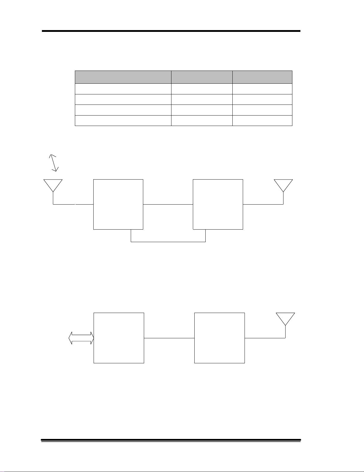
Figure 2-1 illustrates a typical MR Booster application with a repeater, and Figure 22 illustrates a typical application with a BTS. The booster is connected directly to the
coverage antenna port from the repeater or BTS and boosts the downlink signal
power while maintaining dynamic range on the uplink. The booster performs several
basic functions to enhance network coverage:
• The repeater or BTS downlink RF output is filtered, amplified and transmitted,
via the mobile coverage antenna, using high efficiency RF power amplifiers.
• Uplink RF signals from handsets in the coverage area are received at the mobile
antenna, amplified by an LNA, and passed directly to the repeater or BTS.
• Control and alarm monitoring is maintained by MR repeater software or through
two relay contact outputs from the booster.
• Power supply and power amplifier soft-fail redundancies offer increased
reliability.
• A separate uplink diversity path is available as an option.
• Downlink output VSWR monitoring is available as an option.
MR Booster Manual (MN001808-1, 7/99) Page 3
2. System Description
• The Booster is available in one of two output power options (medium and high)
and four frequency ranges:
Band Uplink Downlink
AMPS800 full band 824-849 MHz 869-894 MHz
LMR8-00 full band 806-824 MHz 851-869 MHz
PCS1900 ADB band 1850-1885 MHz 1930-1965 MHz
PCS1900 extended EFC band 1875-1910 MHz 1955-1990 MHz
TO/FROM
BTS
DONOR
ANTENNA
PORT
REPEATER
Table 2-1. Frequency chart
REPEATER
PORT
MOBILE
ANTENNA
PORT
BOOSTER
COVERAGE
ANTENNA
MR
MOBILE
PORT
TO/FROM
MOBILE
SWITCHING
OFFICE
I2C BUS
CONTROL
Figure 2-1. Typical MR Booster Application (Repeater)
BTS
REPEATER
PORT
COVERAGE
ANTENNA
PORT
MR
BOOSTER
Figure 2-2. Typical MR Booster Application (BTS)
COVERAGE
ANTENNA
MOBILE
PORT
Page 4 MR Booster Manual (MN001808-1, 7/99)
Repeater or BTS
main port
PA
COMBINER/
SPLITTER
+26V-A
POWER AMPLIFIERS
+26V-B
PA
COMBINER/
SPLITTER
2. System Description
Main coverage
antenna
MOBILE
DUPLEXER
RPTR
DUPLEXER
Repeater or BTS
diversity port
+26V-A +26V-B
POWER
SUPPLY
A
+12V
Figure 2-3. MR Booster functional block diagram
2.3 Theory of Operation
A block diagram of the basic high-power MR Booster system is shown in Figure 2-3.
In order to simplify the discussion, a repeater-booster installation is assumed as in
Figure 2-1.
POWER
SUPPLY
B
MAIN LNA
DIVERSITY LNA
+12V
+26V
CONTROLLER
I2C
+12V
LOGIC
+12V
Diversity coverage
antenna
UL FILTER
CONTROL I/O
2.3.1 Downlink path
Duplexed RF from the repeater’s coverage antenna port is connected to the
booster downlink port. The repeater duplexer then routes the downlink signal
frequencies to the PA combiner/splitter module.
MR Booster Manual (MN001808-1, 7/99) Page 5

2. System Description
The downlink signal frequencies are then routed to the PA combiner/splitter
module by the repeater duplexer. In the high-power option, the RF is split
into four separate paths by the hybrid combiner/splitter module and
distributed to four RF PAs. In the medium-power option, the RF is split into
two separate paths and distributed to two RF PAs.
NOTE: The multiple amplifiers provide soft-fail redundancy to maintain
minimum output power capability should one or more fail in the field.
The PA outputs are summed in a second combiner/splitter, then routed to the
mobile-side duplexer. The duplexer routes the downlink RF output to the
coverage antenna, which transmits to handsets in the booster coverage area.
2.3.2 Uplink path
Mobile handset transmissions are received at the mobile duplexer port and
routed to the LNA input by the mobile duplexer. The amplified LNA output
is then routed to the repeater duplexer, which is connected to the installed
repeater’s coverage antenna port.
A diversity option offers a second, identical uplink path when diversity is in
use in the donor BTS or repeater.
2.3.3 System control
Control functions include PA keying, fan control, and uplink attenuation
setting. Monitored parameters include PA output power, status, system
temperature, power supply temperature, DC output voltage and status, and
input power source (ac or dc).
Resident software can be accessed via the supplied serial interface cable with
a laptop computer and terminal-emulation software to initialize and customize
the unit during installation or to perform troubleshooting.
The booster can be remotely controlled after installation with a Mikom MR
series repeater via the I2C bus interface cable.
For other applications, or if remote control is not required, a pair of relay
closure outputs from the booster can be user-configured and routed to the
donor system to flag system problems after installation.
Page 6 MR Booster Manual (MN001808-1, 7/99)
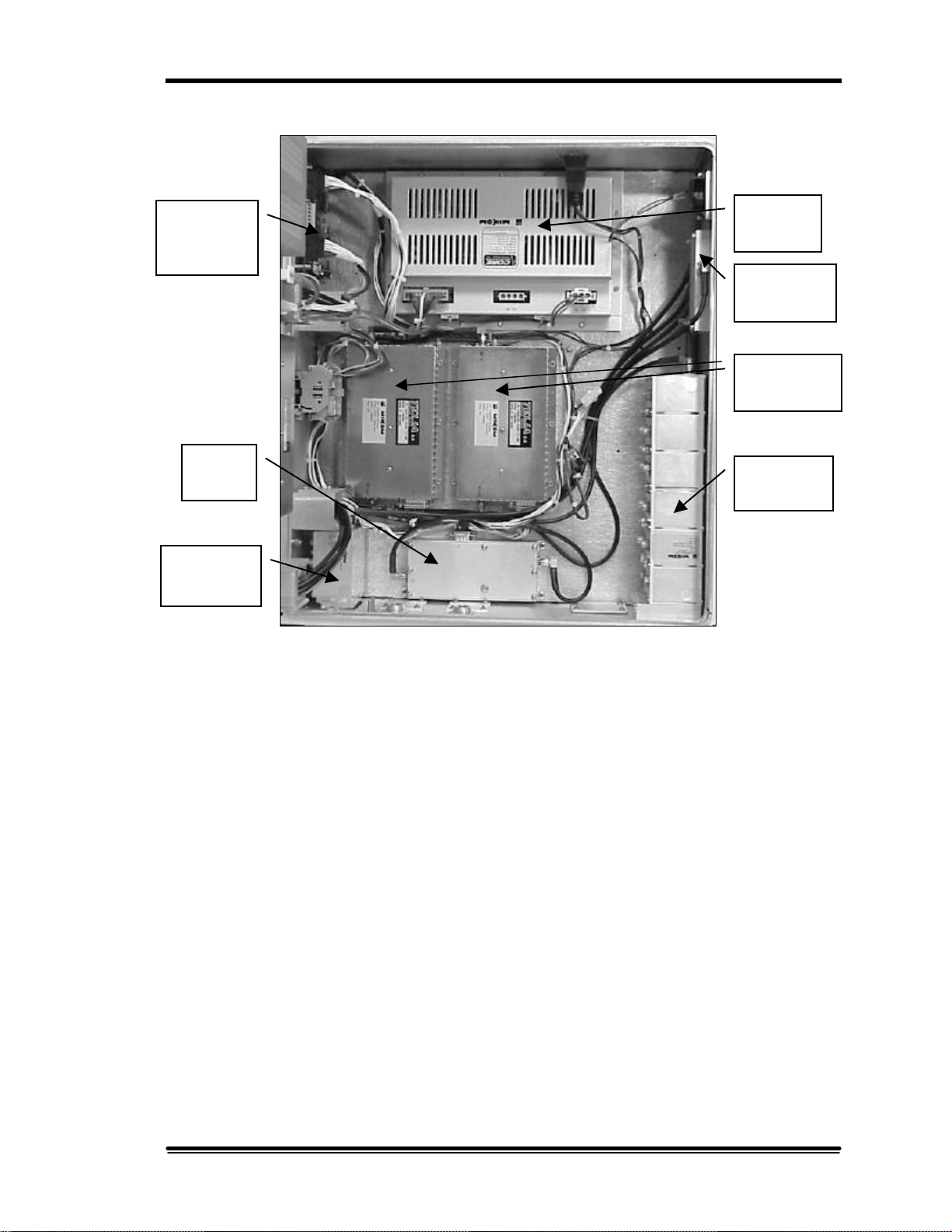
Power
Power
Mobile
Uplink
Logic
Controller
Board
Repeater
Combiner/
2. System Description
Supply
Splitter
Amplifiers
LNA
Duplexer
Duplexer
Figure 2-4. MR Booster (inside cabinet)
MR Booster Manual (MN001808-1, 7/99) Page 7
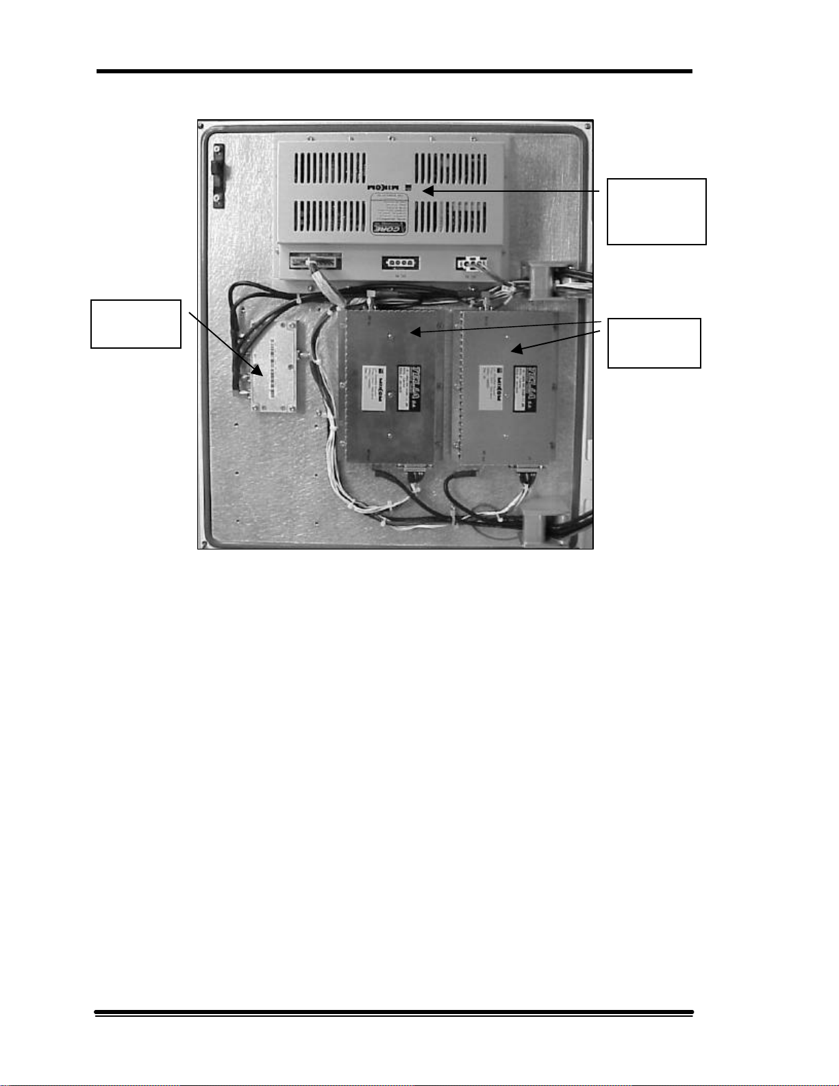
2. System Description
Power
Power
Combiner/
Splitter
Supply
Amplifiers
Figure 2-5. MR Booster (inside door)
Page 8 MR Booster Manual (MN001808-1, 7/99)

2.4 System Components
2.4.1 Power Supply
The MR Booster provides two high-efficiency power supplies with 26 VDC
and 12 VDC outputs (see Figures 2-4 and 2-5). The 26 V output is split
evenly between the system PAs to provide soft-fail redundancy. The 12 V
output is diode-connected at the controller and the LNAs, ensuring that both
will function if a power supply fails. The power supply has thermal
shutdown capability.
The AC supply input is auto-ranging to handle 115 and 220 volt, 50 or 60 Hz
systems. During loss of AC mains, the booster will automatically switch over
to the DC input for operation with a BBU.
2.4.2 Downlink Power Amplifier
The downlink power amplifiers (see Figure 2-4) provide low distortion
amplification of downlink RF signals using proprietary feedforward
correction techniques. After duplexer, splitter and combiner losses, the PAs
provide 20 dB nominal gain for the booster in the downlink signal path.
2. System Description
The amplifiers are powered by the 26 VDC output of the power supplies. To
provide maximum output power and soft-fail redundancy, the downlink power is
shared between either four (high-power option) or two (medium-power option)
PAs. Each PA provides output power and temperature status information to the
system controller and provides both overcurrent and overtemperature protection
circuitry.
2.4.3 Logic Controller Board
The logic controller board (see Figure 2-4) monitors and controls internal
booster functions, and provides alarms to the donor system. The controller
contains an I2C bus interface for remote control by a Mikom MR series
repeater. The controller is powered by the 12 VDC supply.
System configuration information is retained in an on-board EEPROM. For
installation or troubleshooting, the board-resident software can be accessed
from an MR repeater, or from an on-site laptop computer. The controller can
set:
• uplink gain
• PA key/unkey
• fan speed control (high/low/off)
MR Booster Manual (MN001808-1, 7/99) Page 9

2. System Description
The controller monitors the status of the following system components:
• PA power output
• PA temperature
• PA shutdown
• power supply temperature
• average 26 VDC and 12 VDC output voltages
• AC mains presence
• VSWR input (when installed)
The controller also routes the DC power to the VSWR module.
For general use, two alarm outputs are provided that can be user-configured
during installation. The outputs are normally open relay contact pairs, which
are closed when no alarm condition is present. These signals are provided on
four of the seven pins of a terminal block on the controller board.
2.4.4 PA Combiner/Splitter Module
The PA combiner/splitter module (see Figure 2-4) splits the input signal,
distributes it to the PAs and combines it after amplification. Identical hybrid
design is used to ensure maximum amplitude and phase matching of the
downlink signal.
2.4.5 Uplink Low Noise Amplifier
The LNA (see Figure 2-4) maintains dynamic range for uplink mobile
signals. The LNA provides low noise figure and high input IP3 so the booster
does not decrease sensitivity or increase distortion in the system.
The gain of the LNA chain after duplexer and cable losses is nominally 20 dB
with the uplink attenuation set to 0 dB. Using the internal software, the gain
can be reduced by increasing the attenuation in 1 dB steps up to 15 for
optimal IP3, or where equal uplink and downlink booster gain is not
necessary. The same LNA is used in the diversity option and the attenuation
setting is ganged so each uplink path is set for equal gain.
Page 10 MR Booster Manual (MN001808-1, 7/99)
2.4.6 Duplexers
CAUTION:
proper MIKOM part numbers.
The duplexers (see Figure 2-4) provide isolation between uplink and
downlink paths, and band-limit the signals that are either passed to the donor
hardware, or transmitted at the mobile antenna. The small repeater duplexer
provides adequate UL/DL isolation. The mobile duplexer offers low insertion
loss to maximize downlink output power and uplink noise figure. Forward
and reverse directional coupler outputs are provided on the mobile duplexer.
The coupler outputs are routed to the VSWR module when that option is
installed.
2.4.7 RF Cables
The RF cables are a critical part of the MR Booster, particularly in the
downlink function. Low loss provides maximum output power and cable
propagation delays must be properly controlled so that the amplifiers are
combined with low phase error.
2. System Description
Never substitute RF cables in the booster. Use only
2.4.8 Fan Assembly (High-power only)
Dual DC fans (not shown) maintain a low cabinet temperature in the high
power option. The fans are sealed to withstand all weather conditions. The
plenum and ducting structure of the booster is designed to move air over all
heat fins, even if one fan fails. The fans can be disabled or operated at low
speed for climates where over-heating will not be a problem. The logic
controller provides the fan interface.
2.4.9 VSWR Module (Optional)
The VSWR module (not shown) monitors the downlink output VSWR. The
customer is alerted to potentially damaging antenna mismatch. The module
receives ± 12 VDC from the controller and coupled outputs from the mobile side
duplexer. The coupled signals are processed the output VSWR is routed to the
logic controller.
MR Booster Manual (MN001808-1, 7/99) Page 11
2. System Description
2.4.10 Downlink Driver Amplifier (Optional)
An ultra-linear driver amplifier (not shown) provides more downlink gain or
boosts the linear output power. Contact technical support for availability and
details.
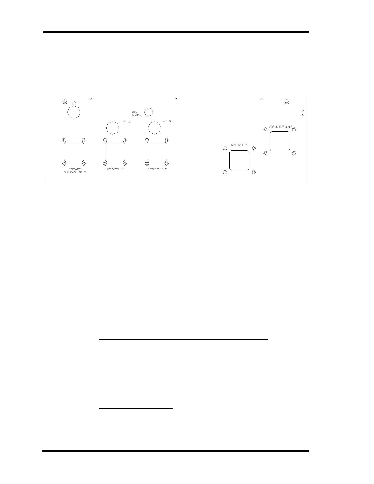
Figure 2-5. Input/output panel
2.4.11 Input/Output Panel
All system inputs and outputs are accessible from the bottom panel of the
cabinet (see Figure 2-5). All RF connectors are 7-16 female bulkhead. All
unused RF ports have gasketed plates covering the connector cutout.
Control, alarm, and power connections are made via multi-conductor cables
routed through weatherproof glands. Unused glands are filled with removable
plugs.
NOTE: The customer is responsible for ensuring a weatherproof seal on
glands not set up in the factory.
Following are the descriptions of the available I/O connections:
• Repeater Duplexer or DL (optionally repeater DL only): Connected to
the repeater’s mobile coverage antenna port. It accepts downlink signals
from the repeater and outputs the uplink RF to the repeater.
NOTE: If the MR Booster must interface with a non-duplexed system,
this port can be used to route the downlink output from the repeater to the
booster.
• Repeater UL (optional): This port is used only when the repeater has
non-duplexed mobile input and output. The uplink output is then routed
through this connector from the booster to the repeater.
Page 12 MR Booster Manual (MN001808-1, 7/99)

2. System Description
• Mobile Duplexer: Connected to the repeater’s coverage antenna.
• Diversity In (optional): The diversity coverage (mobile) antenna is
connected to the diversity input port.
• Diversity Out (optional): The diversity output is routed to the repeater’s
uplink diversity path input port.
• AC IN gland: The AC input cable is passed through this gland and
connected to the WAGO terminal block inside the cabinet.
• DC IN gland: If a DC input is used, the multi-conductor cable is passed
through this gland and distributed to the DC input connector of the power
supplies. Contact the factory for further details if using a customersupplied BBU or DC source.
• I2C gland: The I2C control cable is routed through this gland and
connected to the logic controller board inside the cabinet. The far end of
the cable is connected to the MR series repeater control bus.
• BBU signal gland: This gland is provided to interface to a BBU alarm or
sense output.
MR Booster Manual (MN001808-1, 7/99) Page 13


3.1 Introduction
This section describes the procedures for installation of an MR Booster and system
optimization. The Installation Checklist at the end of this section provides a concise
summary of the installation steps. Section 4 will provide initial software instructions.
3.2 Site Selection
The site chosen for the MR Booster must meet requirements related to location,
power, space, mounting surface, environment, and antenna isolation.
3.2.1 Equipment Inventory
The following table lists items shipped with the MR Booster. Use a separate
table for each booster installed.
Section 3. Installation
MR Booster
Site: Installer:
q MR Booster
Tuck Pack:
q Manual
q 6mm T-handle wrench
q 4mm T-handle wrench
q 3mm T-handle wrench
2
q I
C bus cable
q Serial cable
q Drilling template
q Keys for security cover
Serial #:
Serial Part #:
MN001808-1
G71A0031-2
G71A0031-3
G71A0031-1
G15A0309-1
G15A0327-1
G27AT000-1
???N/A
Table 3-1. Equipment List
MR Booster Manual (MN001808-1, 7/99) Page 15

3. Installation
3.2.2 Installation Tools and Equipment
You will need the following tools and equipment for installation of the MR
Booster:
Factory supplied:
• 6mm T-handle wrench to mount cabinet to bracket
• 4mm T-handle wrench to open/close cabinet door
• DB-9 to DB-9 serial control cable
• I2C bus cable (if applicable)
Customer supplied:
• M8 carriage bolts, flat washers, split lock washers, and drivers to bolt the
mounting bracket to a wall or pole
• Laptop computer with serial port and terminal emulation software (e.g.,
ProComm)
• Coaxial RF cables terminated with a 7-16 male connector
ü for donor port
ü for repeater port or RX port (if applicable)
ü for diversity input (if applicable)
ü for diversity output (if applicable)
ü for TX port (if applicable)
• >30 dB, 60 W attenuator
• RF power meter with 20 dBm power-handling capability
• Miscellaneous RF test cables and adapters
3.2.3 Site Requirements
Space: The MR Booster dimensions are 742 mm (H) x 466 mm (W) x 287
mm (D) (29.2 x 18.3 x 11.3 inches) with fans, 535 mm (H) (21.1 inches)
without fans. Allow a minimum of 500 mm in front of the booster for door
clearance, 30 mm below for cable access, and 150 mm on either side for
access to mounting hardware.
Mounting surface: The cabinet should be mounted to a vertical surface with
a load-bearing capacity of at least 55 kg. It may be mounted to a wall or a
pole.
Page 16 MR Booster Manual (MN001808-1, 7/99)

Environment: The MR Booster is in a weatherproof cabinet that can be
operated at ambient temperatures between -30°C to +55°C.
Power: The cabinet requires 90-264 VAC, 50-60 Hz at 600 Watts maximum,
or 21-28 VDC, 20 Amps maximum (when equipped for DC operation).
Antenna isolation: When the MR Booster is used with a repeater, the
isolation between the donor and mobile antennas must be at least 15 dB
greater than the composite system gain of the repeater plus booster for
optimum performance.
3.3 Installation
3.3.1 Mechanical
Use the supplied template, shown in Figure 3-1, to drill holes to mount the
MR Booster mounting bracket. Install the mounting bracket with two M8
carriage bolts for pole mounting, and four M8 carriage bolts for surface
mounting. Use a flat washer and split lock washer under the head of each
bolt.
3. Installation
WARNING! The MR Booster may weigh up to 51 kg
(112.4 lbs), depending on options; use two people to lift the
booster onto the mounting bracket.
Lift the repeater up and set the top M10 screws into the recesses provided in
the top of the mounting bracket. Align the holes in the cabinet with the holes
in the mounting bracket, then install and tighten the four M8 socket-head cap
screws using the supplied 6mm T-handle wrench.
To access the inside of the cabinet (see Figure 3-2), use the supplied 4mm Thandle wrench to unscrew the four M5 socket-head cap screws that secure the
door to the main cabinet.
MR Booster Manual: (MN001808-1, 7/99) Page 17

3. Installation
Figure 3-1. Drilling template (not to scale)
Page 18 MR Booster Manual (MN001808-1, 7/99)

Door
Access
Screws
3. Installation
Figure 3-2. Door access screws
MR Booster Manual: (MN001808-1, 7/99) Page 19

3. Installation
3.3.2 Electrical Connections
AC: The unit is shipped with the internal AC connections already made. The
cable extends 10 feet outside the cabinet to allow termination to a junction
box or other connection to the AC mains. Since the power supply inputs are
autoranging, no special accommodations are required to connect to standard
voltage and frequency.
The wires are attached to a WAGO connector inside the cabinet as follows:
Wire Color WAGO Color
Brown (hot) Gray
Blue (neutral) Blue
Green/Yellow (ground) Screwed to ground lug
Table 3-2. Wire Chart
DC: Please consult MIKOM at 1 (800) 800-3224 for applications with a
customer-owned DC power source or battery-backup unit.
Page 20 MR Booster Manual (MN001808-1, 7/99)

3.3.3 RF Connections
RF cables to the MR Booster must be terminated with a 7-16 male RF
connector. A low-loss, 50 ohm cable with superior shielding is recommended
for all RF connections. See Section 2.4.11 for I/O options.
3. Installation
Figure 3-3. I/O connections
Minimum configuration (see Figure 3-3) consists of two cables:
• From the duplexed port of the donor repeater to the Repeater Duplexer
connector on the booster.
• From the Mobile Duplexer port of the booster to the coverage antenna.
MR Booster Manual: (MN001808-1, 7/99) Page 21

3. Installation
J1
J6
J7
Terminal
Block
I2C Bus
Connection
Serial
Connection
Figure 3-4. Logic Controller Board
3.3.4 Logic Controller Board
Several connections are made through the I/O panel on the bottom of the
repeater. Figure 3-5 shows the position of applicable connectors.
I2C bus: To enable control functions, such as alarms, from a Mikom repeater,
connect the supplied I2C cable connector to J7 on the logic controller board.
Pass the cable through the I2C gland on the I/O panel. The cable can then be
routed to the MR Repeater’s I2C connector.
Serial control: Connect the female DB-9 end of the supplied serial cable to
J6 on the logic controller board. Route the cable through the door of the
booster and close it (the door seal will prevent the cable from being crushed).
Connect the male end of the serial cable to serial port 1 of the laptop
computer. After initialization or troubleshooting has been completed, this
cable can be removed.
Page 22 MR Booster Manual (MN001808-1, 7/99)

3. Installation
Alarm outputs: The alarm output wires are available from terminal block J1
on the logic controller board. A multiple-conductor cable must be passed
through the I2C gland. The alarm function is defined through software in the
initialization process. Pin out is as follows:
Pin Function
1 Alarm 1
2 Alarm 1 return
3 Alarm 2
4 Alarm 2 return
5 External digital alarm input (optional)
0-5 V TTL level input
6 Ground reference
7 External analog alarm input (optional)
0-30 V analog alarm input
Table 3-3. Alarm pin out
WARNING! Inspect the unit after cabling to ensure that unused
connector holes have plates and gaskets applied, and that unused
glands have stops inserted. All connections should be completed
and weatherproofing ensured before AC mains or DC power is
applied.
MR Booster Manual: (MN001808-1, 7/99) Page 23

3. Installation
3.4 Installation Checklist
The following checklist provides a summary of the procedures for installing an MR
Booster system.
Step Item/ Action Description Check
1
2
3
4
5
6
7
8
9
10
11
MR Booster Site Drawing
Equipment List:
MR Booster
AC or DC power source
Uplink source
Downlink source
Installation tools:
M8 carriage bolts To install mounting bracket
6mm and 4mm drivers To mount cabinet to bracket, open door
Serial control cable To connect terminal to booster
terminal To initialize booster
I2C bus cable (if applicable)
Coaxial cables
>30 dB, 60 W attenuator
RF power meter
Miscellaneous RF test cables
Run cable to site
Mount the equipment
Attach cables
Connect terminal to J6 on the
logic controller board
Power up booster
Initialize booster
Close cabinet and screw shut
Optimize system
Master copy of the site plan noting the MR
Booster location and serial number.
Power, uplink, downlink, I2C (if applicable)
See Section 3.3.
Power, uplink, downlink, I2C (if applicable),
alarm outputs (if applicable)
For initialization.
See Section 4, Setting Up for Initial Operation
See Section 3.5, System Optimization
Table 3-4. Installation checklist
Page 24 MR Booster Manual (MN001808-1, 7/99)

TO/FROM
BTS
REPEATER
DONOR
ANTENNA
PORT
Figure 3-5. Typical MR Booster Application (Repeater)
3.5 System Optimization
MOBILE
ANTENNA
PORT
CONTROL
REPEATER
I2C BUS
PORT
MR
BOOSTER
3. Installation
COVERAGE
ANTENNA
MOBILE
PORT
Refer to Figure 3-5 for an example of an application in which the MR Booster is used
to boost a repeater. For additional information regarding system optimization, please
contact Mikom technical support at 1 (800) 800-3224.
3.5.1 Downlink Gain Setting
The downlink gain is generally determined by the output power that provides
coverage of the hole that the MR Booster is filling. This power should not
exceed the specifications in Section 6 for differing technologies and number
of carriers. The gain of the repeater must be adjusted via the operational
software so that the desired output power equals the system gain (repeater
plus booster) plus the input power received from the BTS.
The input power can be determined from the downlink RSSI reading of the
repeater for each applicable RF channel. For greatest accuracy, the factory
test data sheet enclosed with the MR Booster can be used to determine the
booster gain near each channel of interest.
3.5.2 Downlink Power Measurement
To ensure that the proper output power is reached, measure the composite
power coming out of the mobile duplexer port. Use a power meter capable of
handling 100 mW with a 30 dB, 60 W power attenuator on the mobile
connector for an accurate measurement without damage. The composite
power measured by the meter, after calibrating out the loss of the attenuator,
should be approximately equal to the desired power per carrier plus 10logN,
where N is the number of carriers.
MR Booster Manual: (MN001808-1, 7/99) Page 25

3. Installation
3.5.3 Uplink Gain Setting
In most cases, the repeater gain is adjusted to make the uplink gain equal to
the downlink gain to maintain a balanced link. Adjust the repeater gain, leave
the MR Booster LNA gain set to maximum, and the overall system noise
figure is minimized.
In cases where unusually strong in-band interferers are present, it may be
necessary to decrease the LNA gain in order to increase the overall system
input intercept point. The amount of attenuation added depends on the
required system intercept point, – the maximum allowable system noise
figure and the dynamic range of the repeater.
Page 26 MR Booster Manual (MN001808-1, 7/99)

Section 4. Setting Up for Initial Operation
4.1 Introduction
All MR Booster operating parameters are under software control and can be changed
from a terminal connected via serial link to the booster. The booster has default
settings for optional parameters. These parameters may need to be adjusted for
proper operation in your network.
This section describes procedures for:
• Connecting the terminal
• Becoming familiar with system commands
• Programming initial parameters
The checklist in Table 4-1 presents a brief overview of these procedures. For
descriptions of all operating parameters, see Appendix A, Control Software. If
problems occur during setup, refer to Section 5, Troubleshooting.
MR Booster Manual (MN001808-1, 7/99) Page 27

4. Setting Up for Initial Operation
Setup Checklist
? 1. Terminal connected:
? a. Terminal powered up and set to 9600-N-8-1, full duplex, send carriage return
only, no CTS/RTS, no XON/XOFF.
? b. MR Booster repeater powered up.
? 2. System status (SSS) and alarm (ALA) report checked; no DISABLED and no
alarms shown.
? 3. System parameters programmed:
? a. Gain
? b. PA settings reviewed.
? c. Alarm settings reviewed.
? d. Alarm report reset (ALA=0, press Enter).
? 4. RF performance checked.
Table 4-1. Setup Checklist
4.2 Connecting a Terminal
The MR Booster can communicate with a PC running a terminal-emulation program
such as ProComm, or a conventional ASCII, RS-232 terminal.
1. Using the supplied serial cable, connect the PC COM PORT to J-1 on the
controller board (see Figure 3-4 on Page 22).
2. Power up the terminal and set it to the following parameters:
• 9600 baud
• Non parity
• 8 data bits, 1 stop bit
• Full duplex (no local echo)
• Send carriage return only
• Disable AUTO XON/XOFF
NOTE: Some terminal emulation programs generate extraneous characters that
may cause interference when communicating with the booster.
Page 28 MR Booster Manual (MN001808-1, 7/99)

3. Power up the MR Booster. After about two seconds, the terminal should respond
with a welcome message.
• If the response is garbled, check the terminal setup.
• If there is no response, turn the booster OFF, then ON again. If there is still
no response, turn the unit OFF. Recheck the power hookup and the terminal
hookup and configuration.
4.3 Basic Commands
Following are basic rules and key commands for use with the MR Booster operating
software.
Symbol Definition
4. Setting Up for Initial Operation
>
<CTRL>
<ESC>
4.3.1 Syntax
System commands consist of three letters followed by a maximum of three
data fields, as follows:
COM [FIELD 1 -] [FIELD 2 =] [FIELD 3] Enter
• COM: Three-letter command.
• FIELD 1: Up to four hex characters followed by a dash (-).
• FIELD 2: Up to four hex characters followed by an equal (=) sign.
• FIELD 3: Up to two hex characters.
Command Prompt. The system uses this prompt character to indicate
it is ready to accept commands.
Control Key. Used in combination with other keys.
Escape Key. Escape is a single key marked ESC on most keyboards.
Table 4-2. Command Definitions
• Enter: Press the Enter key after each command.
NOTE: Few commands require entry of data fields. After a command has
been entered, the system will prompt for data it needs. The system will ignore
unneeded data fields.
MR Booster Manual: (MN001808-1, 7/99) Page 29

4. Setting Up for Initial Operation
4.3.2 Entering Commands
When entering commands:
• After the three-letter command has been entered, spaces may be added to
separate the fields.
• Leading zeros may be omitted.
• Use DELETE or BACKSPACE to correct mistakes.
• Press Enter at the end of each command.
4.3.3 Commonly Used Commands
Table 4-3 lists the most commonly used commands. The most complex
command is SET. This command is structured to ensure that parameter entry
can be done easily and accurately. The other commands, which are much
simpler, require little or no subsequent data input. Their actions are completed
in a matter of seconds.
NOTE: To become familiar with these commands, try each command
(except SET) and observe the system's response.
CAUTION: RES will momentarily interrupt any calls
currently being boosted. Otherwise, the system commands do
not interfere with calls being boosted.
Page 30 MR Booster Manual (MN001808-1, 7/99)

Command Meaning Purpose
4. Setting Up for Initial Operation
HEL
HEL A
SET
SSS
ALA
RES
PWR
Help Lists the syntax and function of the primary
commands.
Help All Lists the syntax and function of all commands.
Set up
Prompts a menu-driven entry mode used to inspect
or change all MR Booster operating parameters.
(To exit this command, press <CTRL> X and answer
N, press Enter.)
Show System Status
Lists current repeater parameter settings and
conditions of monitored input parameters.
Alarm report Reports on number of alarm conditions since last
system reset.
Reset Resets the booster. Parameters in effect when the
command is issued will be saved.
Power display Repeatedly lists power readings on the PAs.
(To exit this command, press <ESC> or <CTRL> Z.)
Table 4-3. System Commands
4.3.4 Escaping From Continuous Cycles
Some commands, such as RSS, enter a mode in which the program does
something continuously. To get out of this mode and return to the command
prompt, press <ESC> or <CTRL> Z.
4.3.5 Ending a Session
The RES command preserves extensive parameter changes made during a
session. It ensures that all parameter changes take effect, since all hardware is
initialized after a reset. Also, all alarms conditions counter to 0.
MR Booster Manual: (MN001808-1, 7/99) Page 31

4. Setting Up for Initial Operation
MAIN MENU AMPLIFIERS
POWER SUPPLIES
ACCESSORIES
ALARMS
LNA ATTENUATOR SETTING
POWER SUPPLY 1-2
FAN CON TROL
VSWR
MAX POWER SUPPLY TEMP
MAX PA TEMP
EXTERNAL I/O
CRITICAL ALARMS
TYPE
MAX POWER ALARM POINT
MIN POWER ALARM POINT
POWER SUPPLY TYPE
DIGITAL INPUT ALARM STATE
ANALOG INPUT THRESHOLD
ANALOG INPUT ALARM STATE
OUTPUT 1 STATE
OUTPUT 2 STATE
PA POWER HI ALARM
PA POWER LO ALARM
PA TEMP HI ALARM
PA OUT OF SERVICE ALARM
PA OVERCURRENT/OVERDRIVE ALARM
AC POWER LOST ALARM
POWER SUPPLY REGULATION ALARM
VSWR HI ALARM
DOOR OPEN ALARM
EXTERNAL DIGITAL INPUT TRIPPED
EXTERNAL ANALOG INPUT TRIPPED
EXTERNAL ROM ALARM
EEPROM ALARM
Figure 4-1. SET Command Menu Map
4.4 Using SET Menus
Use the local terminal to configure the MR Booster. From the command prompt (>),
the SET command launches the setup utility, which displays a progression of menus.
The menus provide a guided path to each booster parameter. The menu map in
Figure 4-1 illustrates the SET menu paths. For descriptions of all SET menus and
commands, see Appendix A, Control Software.
4.4.1 Moving Forward
After each command has been entered, a menu is displayed, with a character
in front of each item. To select an item, type the character and press Enter.
The next menu (or the parameter to be changed) will be displayed.
Page 32 MR Booster Manual (MN001808-1, 7/99)

4.4.2 Moving Backward
To move backward along a path, type X and press Enter. This indicates a
"Done with this menu" selection. The previous menu will be displayed.
Continue to back out to the main SET menu.
4.4.3 Exiting
To exit SET, press <CTRL> X at any menu level. Or, type X and press
Enter while at the main menu level.
4.5 Setting Initial Parameters
The MR Booster is shipped with the filters set to default center frequencies. Before
operating the unit, set initial parameters. This includes:
• Checking system status.
• Configuring the system for narrowband or wideband (channel number, band
offset, and gain).
4. Setting Up for Initial Operation
• Reviewing and recording power amplifier and alarm settings.
Setting these parameters is the minimum required to provide performance. All
parameters can be changed to fine-tune the system as more information is gathered
about system performance.
4.5.1 Checking System Status
Check the system status to be sure parameters were properly set after factory
testing.
1. At the > prompt, type SSS, press Enter. (The current state of various
parameters is displayed.)
2. At the > prompt, type ALA Enter. (The number of alarm conditions
since last reset is displayed.)
No alarms should be listed. If there are any Out-of-Service or memory
alarms, refer to Section 5, Troubleshooting.
4.5.2 Setting PA Parameters
From the Main Menu, type B, press Enter to display the Power Amplifiers
Menu.
MR Booster Manual: (MN001808-1, 7/99) Page 33

4. Setting Up for Initial Operation
Power Amplifiers Menu
A Downlink PA Power High Alarm Point...................... +33 43 dBm
B Downlink PA Power Low Alarm Point ...................... +20 dBm
Use the following guidelines and recommendations to set the power amplifier
parameters. These settings should provide serviceable operation. Refer to
Section 3.5, System Optimization, to fine-tune and optimize the settings.
Downlink PA Power High Alarm Point: Set to + 33 43 dBm to trigger an
alarm at that setting.
Downlink PA Power Low Alarm Point: Must be set to 6 dB below the
Forward Maximum Wideband Power. Once initial operation is established,
use the SSS command (see Appendix A, SSS Command) to examine the
downlink PA power output under normal operating conditions. Adjust the
downlink PA Power Low Alarm Point to a few dB below the normal
operating power.
Page 34 MR Booster Manual (MN001808-1, 7/99)

Section 5. Troubleshooting
5.1 Introduction
This section describes methods for locating and resolving problems in an MR
Booster. Instructions are given for replacing some of the major modules in the
system; however, it is recommended that Mikom technical support personnel perform
all MR Booster maintenance. Please call 1 (800) 800-3224 for assistance.
5.2 System Status Indicators
The MR Booster has visual indicators on the logic controller and the power supplies
that are the first indicators of basic system functionality. All other troubleshooting
tools are contained within the user software.
5.2.1 Logic Controller LED Indicators
A green and a red LED on the logic controller board indicate the following
conditions:
Green LED Red LED Operational State
Pulsing OFF Normal state, no alarms.
OFF ON Indicates power applied, but operational
software is not running properly.
OFF OFF No +12 VDC
Table 5-1. Logic controller status indicators
MR Booster Manual (MN001808-1, 7/99) Page 35

5. Troubleshooting
DC system power before servicing.
5.2.2 Power Supply LED Indicators
Each power supply has two green LEDs, which indicate:
AC GOOD DC GOOD BDASTATUS
ON OFF AC input present; DC output not functioning
ON ON AC input present; DC +26 V/+12 V outputs
properly.
OK.
OFF OFF
OFF ON AC power not present; DC input present and
AC power not present; DC source not present
or out of proper voltage range.
+26 V/12 V outputs OK.
Table 5-2. Logic controller status indicators
5.2.3 Logic Controller Software Alarms and Monitoring Parameters
The SSS command, which displays the general status of the booster modules,
and the SET command, which is used to monitor or set operating parameters,
can be used to find component failures. See Section 4 and Appendix A for a
detailed description of the software. Please contact Technical Support at 1
(800) 800-3224 for assistance in troubleshooting system problems.
5.3 Removing and Replacing Failed Parts
It is recommended that only higher failure rate and easily accessible items be
removed from the booster cabinet. The supplied 3mm T-handle wrench may be used
to remove and/or replace a power supply or power amplifier.
Other hardware can be removed from the booster with either standard-size metric
Allen keys or Phillips screwdrivers.
Page 36 MR Booster Manual (MN001808-1, 7/99)
WARNING! It is recommended that trained Mikom technicians
provide service for the MR Booster. Always remove both AC and

6.1 Specifications
This section provides mechanical and electrical specifications for the MR Booster.
Mechanical Specifications
Section 6. Specifications
Dimensions
Weight
(approximate, fully populated)
Operating temperature
Alarm outputs
(user configurable – available
through I2C/alarm gland)
RF I/O
(7-16 female connectors)
Other I/O
(4 weatherproof glands)
742 mm (H) x 466 mm (W) x 287 mm (D), with fans
(29.2 in x 18.3 in x 11.3 in)
535 mm (H) x 466 mm (W) x 287 mm (D), without fans
(21.1 in x 18.3 in x 11.3 in)
51 kg (112 lbs), 4 PAs, with fans
45 kg, (99 lbs) 2 PAs without fans
-30°C to +55°C
Alarm 1: Closed relay contact indicates alarm state
Alarm 2: Closed relay contact pair indicates system
alarm state
Repeater UL/DL
Mobile Antenna
UL diversity input (optional)
UL diversity output (optional)
Repeater DL only (optional)
AC input
DC input
BBU alarm
I2C/alarm
Table 6-1. Mechanical specifications
MR Booster Manual (MN001808-1, 7/99) Page 37

6. Specifications
Electrical Specifications
Power requirements 90-265 Vac, 50-60 Hz: 600 W max (fully loaded)
Automatic switchover to BBU with loss of AC mains
21-26 Vdc, 20 A max (fully loaded)
Frequency bands
(uplink/downlink)
Downlink gain
Downlink gain
variation
Uplink attenuation
setting
(main and diversity)
Uplink gain variation
Uplink noise figure
(main and diversity)
Uplink input IP
3
(main and diversity)
Downlink output power
per communication
format
(typical performance at
25°C)
AMPS800 full band: 824-849/869-894 MHz
LMR8-00 full band: 806-824/851-869 MHz
PCS1900 ADB band: 1850-1885/1930-1965 MHz
PCS1900 extended EFC band: 1875-1910/1955-1990 MHz
20 dB nominal, 19 dB minimum at upper band edge
±1 dB over any frequency band at 25°C
±2 dB over -30°C to +55°C ambient
0 dB to 15 dB from maximum gain in monotonic 1 dB steps
±1 dB over any frequency band at 25°C
±2 dB over -30°C to +55°C ambient
3 dB typical at 0 dB attenuation
10 dBm typical
# of
carriers
GSM1900,
analog:
TDMA:
med/high pwr
CDMA, iDEN:
med/high pwr
med/high pwr
1 42.5* 45.0* 42.5 45.0 39.5 42.0
2 39.5 42.0 36.5 39.0 33.5 36.0
4 35.5 38.0 32.5 35.0 30.5 33.0
8 31.5 34.0 29.5 32.0 27.5 30.0
Table 6-2. Electrical specifications
* Limited by maximum PA current.
Page 38 MR Booster Manual (MN001808-1, 7/99)

Electrical Specifications (Continued)
6. Specifications
Control modes
Control parameters
Monitor parameters
Module alarms
Stand-alone serial mode: Uplink gain, booster control, and
monitor signals passed via DB-9 connector on controller PCB
(pre-operational), alarms outputs available via I2C/alarm gland
(operational).
Repeater control: All booster control and monitor functions
maintained through MR-701/801 repeater software with
communication via I2C bus.
Stand-alone manual mode: Uplink gain set via switch on
controller PCB, alarms outputs available via I2C/alarm gland.
PA 1-4 shutdown
Fan 1, 2 speed control (high, low, off)
Uplink LNA attenuation setting (0-15 dB)
PA 1-4 output power
PA 1-4 temperature
Power supply 1, 2 temperature
Power supply average DC output voltages (+26 V, +12 V)
PA 1-4 shutdown
ac mains 1, 2 power absent
Table 6-2. Electrical specifications (Continued)
Indoor
MR Booster Manual (MN001808-1, 7/99) Page 39


MR Booster Manual
Appendices
Order No. MN001808-1
Issue 7/99
©
Copyright 1999 Mikom
All Rights Reserved


Contents
Page
MR Booster Manual: Appendices (MN001808-1, 7/99) Page iii


Appendix A: Control Software
A.1 Introduction
Extensive monitoring software included with the MR Booster allows the installer or
service provider to control and monitor the system's performance.
This section includes a description of the terminal interface to the booster, which is
used to set parameters, monitor system status, and report and diagnose problems. It
includes procedures for entering commands and setting parameters and provides
information on interpreting the results.
For instructions on installing the MR Booster, setting initial parameters, and making
adjustments to achieve optimum performance, refer to Section 3, Installation, and
Section 4, Setting Up for Initial Operation.
A.2 Connecting a Terminal
The MR Booster can communicate with a PC running a terminal-emulation program
such as ProComm, or a conventional ASCII, RS-232 terminal.
1. Using the supplied serial cable, connect the PC COM PORT to J-1 on the
controller board (see Figure X-X).
2. Power up the terminal and set it to the following parameters:
• 9600 baud
• Non parity
• 8 data bits, 1 stop bit
• Full duplex (no local echo)
• Send carriage return only
• Disable AUTO XON/XOFF
NOTE: Some terminal emulation programs generate extraneous characters that
may cause interference when communicating with the booster.
MR Booster Manual: Appendices (MN001808-1, 7/99) Page A-1

A. Software Control
3. Power up the MR Booster. After about two seconds, the terminal should respond
with a welcome message.
• If the response is garbled, check the terminal setup.
• If there is no response, turn the booster OFF, then ON again. If there is still
no response, turn the unit OFF. Recheck the power hookup and the terminal
hookup and configuration.
A.3 Basic Commands
Following are basic rules and key commands for use with the MR Booster operating
software.
Symbol Definition
>
<CTRL>
<ESC>
A.3.1 Syntax
System commands consist of three letters followed by a maximum of three
data fields, as follows:
COM [FIELD 1 -] [FIELD 2 =] [FIELD 3] Enter
• COM: Three-letter command.
• FIELD 1: Up to four hex characters followed by a dash (-).
• FIELD 2: Up to four hex characters followed by an equal (=) sign.
• FIELD 3: Up to two hex characters.
Command Prompt. The system uses this prompt character to indicate
it is ready to accept commands.
Control Key. Used in combination with other keys.
Escape Key. Escape is a single key marked ESC on most keyboards.
Table A-1. Command Definitions
• Enter: Press enter at the end each command.
NOTE: Few commands require entry of data fields. After a command has
been entered, the system will prompt for data it needs. The system will ignore
unneeded data fields.
Page A-2 MR Booster Manual: Appendices (MN001808-1, 7/99)

A.3.2 Entering Commands
When entering commands:
• After the three-letter command has been entered, spaces may be added to
separate the fields.
• Leading zeros may be omitted.
• Use DELETE or BACKSPACE to correct mistakes.
• Press Enter at the end of each command.
A.3.3 Commonly Used Commands
Table A-2 lists the most commonly used commands. The most complex
command is SET. This command is structured to ensure that parameter entry
can be done easily and accurately. The other commands, which are much
simpler, require little or no subsequent data input. Their actions are completed
in a matter of seconds.
A. Software Control
NOTE: To become familiar with these commands, try each command
(except SET) and observe the system's response.
CAUTION: RES will momentarily interrupt any calls
currently being boosted. Otherwise, the system commands do
not interfere with calls being boosted.
MR Booster Manual: Appendices (MN001808-1, 7/99) Page A-3

A. Software Control
Command Meaning Purpose
HEL
HEL A
SET
SSS
ALA
RES
PWR
Help Lists the syntax and function of the primary
commands.
Help All Lists the syntax and function of all commands.
Set up
Prompts a menu-driven entry mode used to inspect
or change all MR Booster operating parameters.
(To exit this command, press <CTRL> X and answer
N, press Enter.)
Show System Status
Lists current repeater parameter settings and
conditions of monitored input parameters.
Alarm report Reports on number of alarm conditions since last
system reset.
Reset Resets the booster. Parameters in effect when the
command is issued will be saved.
Power display Repeatedly lists power readings on the PAs.
(To exit this command, press <ESC> or <CTRL> Z.)
Table A-2. System Commands
A.3.4 Escaping From Continuous Cycles
Some commands, such as RSS, enter a mode in which the program does
something continuously. To get out of this mode and return to the command
prompt, press <ESC> or <CTRL> Z.
A.3.5 Ending a Session
The RES command preserves extensive parameter changes made during a
session. It ensures that all parameter changes take effect, since all hardware is
initialized after a reset. Also, all alarms conditions counter to 0.
Page A-4 MR Booster Manual: Appendices (MN001808-1, 7/99)

A.4 SET Command
From the command prompt (>), the SET command launches the setup utility, which
displays a progression of menus. The menus provide a guided path to each booster
parameter. The menu map in Figure A-1 illustrates the SET menu paths. Table A-3
summarizes the alarm parameters that can be programmed using the SET command.
• Moving Forward: After each command has been entered, a menu is displayed,
with a character in front of each item. To select an item, type the character and
press Enter. The next menu (or the parameter to be changed) will be displayed.
• Moving Backward: To move backward along a path, type X and press Enter.
This indicates a "Done with this menu" selection. The previous menu will be
displayed. Continue to back out to the main SET menu.
• Exiting: To exit SET, press <CTRL> X at any menu level. Or, type X and press
Enter while at the main menu level.
A. Software Control
MR Booster Manual: Appendices (MN001808-1, 7/99) Page A-5

A. Software Control
Figure A-1. SET Command Menu Map
Page A-6 MR Booster Manual: Appendices (MN001808-1, 7/99)

A. Software Control
Parameter Options Default Description
PA TEMP - HIGH ALARM POINT 0 (Disabled)
1−100° C
DC POWER - LOW ALARM POINT 0 (Disabled)
0.1−14.9 Volts
AC POWER LOST - ALARM POINT 0 (Disabled)
1−250
PS TEMP ALARM Enabled
Disabled
DOOR OPEN ALARM Enabled
Disabled
EXTERNAL ANALOG INPUT
ALARM STATE (For each of 3 inputs)
EXTERNAL DIGITAL INPUT ALARM
STATE (For each of 3 inputs)
EXTERNAL DIGITAL OUTPUT
CURRENT STATE (For 2 outputs)
0−5 volts
(0) Disabled
(1) Above threshold
(2) Below threshold
(0) Disabled
(1) High
(2) Low
(1) High
(2) Low
(3) High if alarm. . .
(4) Low if alarm. . .
90° C
10.0 Volts Alarm thresholds for power supply
10 x 0.1
minutes
Enabled Enables alarm for power supply
Enabled Enables door open alarm.
0.0 Vdc Defines alarm condition on the
Disabled Defines alarm conditions on the
Disabled Defines alarm conditions on the
Low Defines state of the two general-
Defines PA temperature alarm
condition.
voltages
Defines duration of no ac for alarm.
over temperature.
three analog inputs.
three analog inputs.
three general-purpose inputs.
purpose outputs.
Parameter Options Default Description
CRITICAL ALARMS:
PA Out-of-Service Alarm
PA Temp - High Alarm
PA Power - Low Alarm
ROM Alarm
RAM Alarm
NOVRAM Alarm
PS Voltages - Low Alarm
AC Power Lost Alarm
PS Temp Alarm
Door Open Alarm
External Analog Input Alarm
External Digital Input - Alarms
Log only or
Critical
Critical
Critical
Critical
Critical
Critical
Critical
Critical
Critical
Critical
Critical
Critical
Critical
"Log only" alarm
occurrences will be logged;
total number of occurrences
can be viewed using the
ALA command.
"Critical" alarms will not
only be logged, but also ???
Table A-3. Alarm Parameters
MR Booster Manual: Appendices (MN001808-1, 7/99) Page A-7

A. Software Control
A
A.4.1 Main Menu
Entry: At the > prompt, type SET, press Enter.
Menu:
Main Setup Menu
B Power Amplifiers Menu
D Alarms Menu
E Set Defaults
Purpose: Gives access to setup menus.
NOTE: Use caution with selection E, Set Defaults.
A.4.2 Power Amplifiers Menu
Entry: From the Main Menu, at the > prompt, type B, press Enter.
Menu:
Power Amplifiers Menu Default
Forward PA Power High Alarm Point ................................ ..+33 dBm
B Forward PA Power Maximum AGC Threshold...................... +31 dBm
C Forward PA Power Low Alarm Point................................ ....+20 dBm
D Reverse PA Power High Alarm Point................................ ....+33 dBm
E Reverse PA Power Maximum AGC Threshold...................... +31 dBm
F Reverse PA Power Low Alarm Point................................ .....DISABLED
Purpose: Gives access to each PA parameter.
A: Forward PA Power High Alarm Point
Entry: From the Power Amplifiers Menu, type A, press Enter.
Purpose: To define the maximum acceptable RF power output. If the
level exceeds that figure, an alarm will be logged.
Options:
• Allowable range: +20 to +35 dBm
• Default: +33 dBm
Page A-8 MR Booster Manual: Appendices (MN001808-1, 7/99)

B: Forward PA Power Maximum AGC Threshold
Entry: From the Power Amplifiers Menu, type B, press Enter.
Purpose: To set the RF power level at which the booster will begin to
cut back gain. If this level is exceeded, the gain is reduced by 4 dB
every Gain Control Period until the RF power level is below the AGC
threshold or until the PA is shut down.
Options:
• Allowable range: +20 to +35 dBm
• Default: +31 dBm
C: Forward PA Power Low Alarm Point
Entry: From the Power Amplifiers Menu, type C, press Enter.
Purpose: To define the minimum acceptable RF power output. If the
level exceeds that figure, an alarm will be logged.
A. Software Control
Options:
• Allowable range: +20 to +35 dBm
• Default: +20 dBm
NOTE: The system will not log a PA Power Low Alarm if there is
not sufficient input RSSI to drive the amplifier with the current gain.
D: Reverse PA Power High Alarm Point
Entry: From the Power Amplifiers Menu, type D, press Enter.
Purpose: To define the maximum acceptable RF power output. If the
level exceeds that figure, an alarm will be logged.
Options:
• Allowable range: +20 to +35 dBm
• Default: +33 dBm
MR Booster Manual: Appendices (MN001808-1, 7/99) Page A-9

A. Software Control
A
E: Reverse PA Power Maximum AGC Threshold
F: Reverse PA Power Low Alarm Point
Entry: From the Power Amplifiers Menu, type E, press Enter.
Purpose: To set the RF power level at which the booster will begin to
cut back gain. If this level is exceeded, the gain is reduced by 4 dB
every Gain Control Period until the RF power level is below the AGC
threshold or until the PA is shut down.
Options:
• Allowable range: +20 to +35 dBm
• Default: +31 dBm
Entry: From the Power Amplifiers Menu, type F, press Enter.
Purpose: To define the minimum acceptable RF power output. If the
level exceeds that figure, an alarm will be logged.
Options:
• Allowable range: +20 to +35 dBm
• Default: Disabled
NOTE: The system will not log a PA Power Low Alarm if there is
not sufficient input RSSI to drive the amplifier with the current gain.
A.4.3 Alarms Menu
Entry: From the Main Menu, at the > prompt, type D, press Enter.
Menu:
Alarms Menu Default
PA Temp – High Alarm Point ................................ .............. 90° C
C DC Power – Low Alarm Point................................ .............. 10.0 V
D AC Power Lost – Alarm Point ................................ .............. 10 (x 0.1 Min)
E PS Temp Alarm................................ ................................ ...ENABLED
F Door Open Alarm................................ ................................ ENABLED
G External Analog Inputs Menu
H External Digital Inputs Menu
I External Digital Outputs Menu
J Critical Alarms Menu
Purpose: Gives access to parameters that generate alarm conditions. Each
condition may be designated “log only” or “critical.”
Page A-10 MR Booster Manual: Appendices (MN001808-1, 7/99)

A: PA Temp – High Alarm Point
Entry: From the Alarms Menu, type A, press Enter.
Purpose: To define the maximum acceptable PA temperature.
Temperatures above this limit will cause an alarm to be logged.
Options:
• Allowable range: 0-200º C
• Default: 90º C
C: DC Power – Low Alarm Point
Entry: From the Alarms Menu, type C, press Enter.
Purpose: To specify the +12 V supply voltage alarm threshold. An
alarm is generated if the +12 V reading is equal to or lower that this
voltage. This alarm indicates a problem with the power supply,
harness wiring, or connectors.
A. Software Control
Options:
• Allowable range: 0 (Disabled), 0.1 to 14.9 V
• Default: 10.0 V
D: AC Power Lost Alarm Point
Entry: From the Alarms Menu, type D, press Enter.
Purpose: To specify the duration of an AC power outage that will
cause an alarm to log.
Options:
• Allowable range: 0 (Disabled), 1 to 250 X 0.1 Minutes
• Default: 10 X 0.1 Minutes
E: PS Temp Alarm
Entry: From the Alarms Menu, type E, press Enter.
Purpose: To enable or disable the alarm for the power supply over
temperature.
Options:
• Allowable range: Enabled or Disabled
• Default: Enabled
MR Booster Manual: Appendices (MN001808-1, 7/99) Page A-11

A. Software Control
3
Ext. Analog Input 3 Alarm State
..........
DISABLED
;Input Currently 0.0 Volts
F: Door Open Alarm
G: External Analog Inputs Menu
Entry: From the Alarms Menu, type F, press Enter.
Purpose: To enable or disable the door open alarm.
Options:
• Allowable range: Enabled or Disabled
• Default: Enabled
NOTE: The Door Open Alarm will not log for 10 minutes after an
ALA=0 or RES command. This will allow the operator time to
disconnect the local terminal and close the door.
Entry: From the Alarms Menu, type G, press Enter.
Menu:
External Analog Inputs Menu Default Values
1 Ext. Analog Input 1 Alarm State .......... DISABLED ;Input Currently 0.0 Volts
2 Ext. Analog Input 2 Alarm State .......... DISABLED ;Input Currently 0.0 Volts
Purpose: Allows setting of the alarm conditions for the external
analog inputs. Up to three analog inputs may be connected (see
Section 3.3.4.
Options:
• Allowable entries:
(0) DISABLED
(1) ABOVE
(2) BELOW
• The input alarm points are individually controllable; if above or
below is selected, a threshold between 0.1 and 5.0 V may be
specified.
• Default: (0) DISABLED
Page A-12 MR Booster Manual: Appendices (MN001808-1, 7/99)

A. Software Control
H: External Digital Inputs Menu
Entry: From the Alarms Menu, type H, press Enter.
Menu:
External Digital Inputs Menu Default Values
1 Ext. Digital Input 1 Alarm State ........... DISABLED ;Input Currently HIGH
2 Ext. Digital Input 2 Alarm State ........... DISABLED ;Input Currently HIGH
3 Ext. Digital Input 3 Alarm State ........... DISABLED ;Input Currently HIGH
Purpose: Allows setting of the alarm conditions for the external
digital inputs. Up to three digital inputs may be connected (see
Section 3.3.4).
Options:
• Allowable entries:
(0) DISABLED
(1) HIGH
(2) LOW
• Default: (0) DISABLED
I: External Digital Outputs Menu
Entry: From the Alarms Menu, type I, press Enter.
Menu:
External Digital Inputs Menu Default Values
1 Ext. Digital Output 1 State ................................ ........... LOW
2 Ext. Digital Output 2 State ................................ ........... LOW
Purpose: Allows setting of the state for the external digital outputs.
Up to two digital outputs may be connected. The outputs may be used
to control external equipment (see Section 3.3.4). Also, options (1)
and (2) support using external monitoring equipment to be connected
to the MR Booster.
Options:
• Allowable entries:
(0) LOW
(1) LOW IF CRITICAL ALARM EXISTS
(2) HIGH IF CRITICAL ALARM EXISTS
(3) HIGH
• Default: (0) LOW
MR Booster Manual: Appendices (MN001808-1, 7/99) Page A-13

A. Software Control
N
J: Critical Alarms Menu
Entry: From the Alarms Menu, at the > prompt, type J, press Enter.
Menu:
Critical Alarms Menu Default
J PA OUT-OF-SERVICE ALARM ................................ ........CRITICAL
K PA TEMP – HIGH ALARM ................................ ................ CRITICAL
L PA POWER – HIGH ALARM ................................ ............. CRITICAL
M PA POWER – LOW ALARM................................ .............. CRITICAL
ROM ALARM................................ ................................ ....CRITICAL
P NOVRAM ALARM................................ ............................ CRITICAL
Q POWER SUPPLY VOLTAGE – LOW ALARM................... CRITICAL
R AC POWER LOST ALARM................................ ................ CRITICAL
S PA TEMP ALARM ................................ ............................. CRITICAL
T DOOR OPEN ALARM................................ ........................ CRITICAL
U EXTERNAL ANALOG INPUT ALARM............................. CRITICAL
V EXTERNAL DIGITAL INPUT - ALARMS ......................... CRITICAL
Purpose: Displays a list of logged alarms. Any alarm may be set to
“log only” or “critical.”
Options:
• Allowable entries:
(1) CRITICAL
(2) LOG ONLY
• Default: (1) CRITICAL
A.5 System Monitoring Commands
The MR Booster software monitors the status and performance of the system through
simple commands. Each command is entered at the command prompt (>). The
following commands are described in this section:
• SSS (Show System Status) Command
• ALA (Alarm Report) Command
• PWR (PA Power Display) Command
• REV (Show Software Revision) Command
Page A-14 MR Booster Manual: Appendices (MN001808-1, 7/99)

A.5.1 SSS (Show System Status) Command
Entry: At the > prompt, enter SSS press Enter.
Purpose: Lists a one-page report of selected MR Booster operating
parameters, along with the conditions of inputs that are monitored, then
returns to the command entry level. Figure X-X shows a sample SSS report.
Items listed in the report are described on the following pages.
Reported Items:
• BOARD MODE: Operating mode of each board:
ü Enabled: Indicates the board is actively repeating signals in both
forward and reverse directions.
ü Standby: Indicates the board is OK, but not currently Active due to a
problem with another element in the system. Normally, a board that is
Standby will automatically go back to Active if the problem on the
board or PA is cleared up.
ü Disabled: Indicates either that the board status is set to None or
Disabled (i.e., the board has been disabled by the user) or that the
board is Disabled due to an alarm condition. If the latter case is true,
the ALA command will show an OUT OF SERVICE alarm that
caused the out-of-service condition.
A. Software Control
>sss
To come . . .
• BOARD TYPE: Board type as read from the actual hardware. The
Figure X-X. Sample SSS Report
installed boards have a built-in personality identifier that is read and
reported. Board types are indicated as follows:
ü Wideband boards:
- Cellular: Indicates the band and service the board is designed to
support.
- 1.25 MHz: Indicates the bandwidth of the filters on the board.
ü None: No board is detected, or there is a hardware communication
problem between the RF board and the controller. (The rest of the
display for that column will be blank.)
MR Booster Manual: Appendices (MN001808-1, 7/99) Page A-15

A. Software Control
• PA MODE: Active, Standby, or Disabled. A PA cannot be disabled by
the user. If a PA MODE is Disabled, it is always due to an alarm on that
PA.
• PA POWER (DBM): Power output indication (nominal level at the
antenna connection).
• PA TEMP (DEG C): Temperature reading of the PA.
• DC VOLTAGE: The current voltage reading of the (nominal) 13.8 Volt
supply. Range: 0-20 Volts.
• AC SUPPLY: OK or LOST FOR X MINUTES. Indicates if ac is
present, or, if lost, for how long.
• POWER SUPPLY TEMP: ???
• CABINET DOOR: OPEN or CLOSED.
• EXT. ANALOG VOLTAGES: Voltages at the three general-purpose
analog inputs. Range: 0-5 Volts.
• EXT. DIGITAL I/O: Shows the current state of the three general-
purpose digital inputs and two general-purpose digital outputs. Range:
HIGH or LOW.
A.5.2 ALA (Alarm Report) Command
Entry: At the > prompt, enter ALA press Enter.
Purpose: Displays a report of the number of alarm conditions that have
occurred since the last system reset, then returns to the > prompt. Figure X-X
shows a sample ALA report. Reported alarms are described on the following
pages.
>ala
to come . . .
Figure X-X. Sample ALA Report
Reported Alarms Description:
• Counts stop at 63.
• All counts are zeroed after a power reset or a RES command. Counts may
be zeroed by entering ALA=0.
Page A-16 MR Booster Manual: Appendices (MN001808-1, 7/99)

A. Software Control
• Alarm log rate: Some alarms are checked as often as five times a second.
To prevent a single alarm condition from running up the count, a given
alarm is logged, at most, one time in 10 minutes. The alarm counts may
be interpreted as the number of 10-minute intervals in which the alarm
occurred.
There are two exceptions to this: the board and PA Out of Service alarms,
which are really not logs at all, but reflect the current condition of the
board or PA.
• Automatic Restore to Service: If an alarm condition causes a board or
PA to be taken out of service, the system will continue to process calls
using available boards and PAs until no calls are up. At that time, the
controller will attempt to restore out-of-service boards to service by
resetting the boards.
After the boards reset???, the controller power -on diagnostics are run on
all boards and PAs. These diagnostics check for all alarms that may cause
a board or PA to be out of service, and if an alarm of that type occurs, the
board or PA remains out of service. If a board or PA fails to come back in
service, the controller repeatedly tries to restore boards or PAs to service
(during times when no calls are up) up to 10 times, the last seven of
which are spaced at least 1 hour apart. Note that regardless of whether the
board or PA comes back in service, the original alarm that caused the
problem is still maintained in the log. Except for the Out of Service
alarms, the only way alarms can be zeroed is with ALA=0 or a system
reset.
PA Alarms Reported:
• PA OUT OF SERVICE ALARM: PA currently out of service. If the
measured PA power exceeds the Maximum Power AGC Threshold level,
the controller will reduce the gain in 4 dB steps, as long as the condition
persists, down to the minimum setting. If the output power still exceeds
the Maximum Power AGC Threshold, the PA will be taken out of service.
(If the PA mode displayed by the SSS command is DISABLED, the PA
has been taken out of service.)
MR Booster Manual: Appendices (MN001808-1, 7/99) Page A-17

A. Software Control
When a PA goes out of service, the MR Booster will attempt to bring it
back into service by re-initializing the RF hardware, including the
boards??? and the PAs. Because an out-of-service PA is usually due to
an oscillation condition, the system does not attempt immediately to bring
it back. Rather, the system will attempt a restore-to-service once each
hour, as long as the PA continues to go back out of service. After seven
such attempts, the system will discontinue restore-to-service attempts to
that PA, leaving it out of service. However, if another board or PA goes
out of service, it will trigger its own set of restarts, any of which might
bring back any or all out-of-service boards or PAs.
• PA TEMP HIGH ALARM: PA temperature above the Maximum PA
Temperature Alarm Point parameter.
• PA POWER HIGH ALARM: PA output power above the Maximum
Power Alarm Point parameter. Following is a list of possible causes:
ü Improper setting of the PA Power High Alarm Point with respect to
ü Failure of the AGC algorithm to keep the power in check
ü Too much gain
ü Oscillation
the PA Power AGC Threshold
• PA POWER LOW ALARM: PA output power below the Minimum
Power Alarm Point parameter at a time when RSSI and gain are sufficient
to cause that much power. Following is a list of possible causes:
ü PA failure
ü Board failure (either low gain or inaccurate RSSI reporting)
ü Problem with one of the RF cables that couple the boards and PAs
System Alarm Conditions Reported:
• ROM ALARM: Problem in Read Only Memory. (Checked at power-up
by computing a ROM checksum and comparing it with a stored
checksum. Note: The CHK command will recompute the ROM checksum
and display the stored checksum but will not check for a match.)
• NOVRAMALARM: Problem in Nonvolatile Memory. (Checked at
power-up by looking for several "signature bytes" that indicate if data
have ever been written and if gross memory loss has occurred. If the
signature cannot be found, the system tries to write the defaults [and the
signature] to the NOVRAM.
ü Alarm readings:
0 = No problems.
Page A-18 MR Booster Manual: Appendices (MN001808-1, 7/99)

A. Software Control
1 = Signature not found, but system was able to write it
successfully. (All operating parameters will revert to their
default values.) Software upgrades usually result in this
reading, since different versions employ different signatures.
Repeated occurrences indicate an intermittent NOVRAM.
2 = Signature not found; system could not write the signature.
Indicates faulty NOVRAM circuitry.
• DC VOLTAGE LOW ALARM: The +12 volt supply went below the
associated Low Alarm Point. The voltages are monitored at the controller
board. A monitored supply voltage point must be in the alarm condition
for at least 1 second before an alarm is logged. Shorter duration dips
below the alarm points are ignored.
• AC SUPPLY LOST ALARM: This alarm is logged if the AC power is
lost for a period of time longer than the AC Power Lost - Alarm Point
duration.
• POWER SUPPLY TEMP ALARM: This alarm count indicates the
number of 10-minute intervals during which the power supply
temperature exceeded its internally set Max Operating Point.
• CABINET DOOR OPEN ALARM: This alarm count indicates the
number of 10-minute intervals during which the cabinet door was
detected to be open for at least 1 second.
NOTE: Alarm will not be logged for 10 minutes after an ALA=0 or RES
command. This allows the operator time to disconnect the local terminal
and close the door.
• EXT. ANALOG ALARMS: Indicates the number of times the voltage
on the general-purpose analog input has gone above or below the
threshold specified in the Ext. Analog Input Alarm State parameter. An
external analog input alarm condition must persist for at least 1 second
before an alarm is logged. Shorter durations are ignored.
• EXT. DIGITAL ALARMS: Indicates the number of times the input has
been different from the Ext. Digital Input Alarm State parameter if
enabled. An external digital input alarm condition must persist for at
least 1 second before an alarm is logged. Shorter durations are ignored.
A.5.3 PWR (PA Power Display) Command
Entry: At the > prompt, enter PWR, press Enter, or PWR X , press Enter
where X is 1-3 (2 or 4 depending on # of PAs??? How are they numbered in
the cabinet???) indicating the display option desired.
MR Booster Manual: Appendices (MN001808-1, 7/99) Page A-19

A. Software Control
Purpose: The PWR command allows the user to continuously monitor the
PA power. Also, PWR allows continuous monitoring of other PA parameters
by choosing options 2-3. Each of the PWR options causes a selected SSS
display line to be displayed on a continuously updated basis. The information
has the same meaning as with SSS. Figure X.X shows a sample list of power
readings.
>pwr
OPTIONS: 1-PA PWR; 2 -PA TEMP; 3-PA MODE... ENTER CHOICE (1-3): 1
PA FWD REV
PA POWER (DBM) +25 +0
PA TEMP (DEG C) +32 +33
PA MODE ENABLED ENABLED
<ESCAPE>
Figure X.X. Sample List of Power Readings
A.5.4 REV (Show Software Revisions) Command
Enter: From the > prompt, enter REV press Enter.
Purpose: Shows the controller board software revision, date code, and serial
number.
Page A-20 MR Booster Manual: Appendices (MN001808-1, 7/99)

A. Introduction
This part of the manual provides information about MR Booster parts, including:
• Model numbers: MR Booster model numbers.
• Suggested spares: Suggestions for replacement parts to be kept on hand,
according to system size.
• Replacing parts and accessories: Procedures for exchanging units under
warranty (see page iv for product warranty) as well as those not under warranty,
and for purchasing spare parts.
B. Model Numbers
The figure below explains the meaning of each character in the MR Booster model
number.
Parts & Accessories
Order Information
Example: MRBDUP19L
MRB DUP 19 L
MR Booster Options:
BASE: Basic cabinet
DUP: Donor duplexer
RDUP: Downlink duplexer
AMP4x: High power
AMP2x: Medium power
DIV: With diversity
PREAMP: Downlink amplifier
VSWR: Antenna VSWR
Frequency Bands
LMR800: 07
AMPS800: 08
PCS ADB: 19
PCS EFC: 19
Frequency sub-bands
(duplexer and diversity
options only):
L: PCS ADB blocks
H: PCS extended EFC blocks
X: Full-band coverage
Table Parts-1. Model numbers
MR Booster Manual: Parts & Accessories (MN001808-1, 7/99) Parts-1

Parts & Accessories Order Information
C. Suggested Spares
The recommended spares per number of fielded MR Boosters is shown below.
Follow instructions in Section C to purchase spare components
Part Recommendation Part Number
Power supply 1 per 5 systems G59A0021-1
Power amplifier 2 per 5 high-power systems G75A0049-1
LNA 1 per 10 systems A001762.G2
Logic controller board 1 per 10 systems A001769-1
Combiner/splitter 1 per 10 systems 2-way: A001748.G3
Fans 1 per 5 high-power systems G45AF005-1
Table Parts-2. Spare parts list
4-way: A001748.G4
Parts-2 MR Booster Manual: Parts & Accessories (MN001808-1, 7/99)

D. Replacing Parts and Accessories
To order spare or replacement parts, refer to the following instructions:
Parts & Accessories Order Information
I. Exchange Procedures: Units Under Warranty
1
Failed MR Booster parts that are still under the manufacturer's warranty can be
exchanged by following these procedures:
1. Obtain the model or part number of the MR Booster unit, as listed earlier
in this section.
2. Call the MIKOM Hotline at 1 (800) 800-3224. Be prepared to provide
the part number and any other pertinent information.
3. Repair parts/assemblies will be shipped. MIKOM will ship replacement
parts or assemblies with a Return Materials Authorization (RMA) form.
This form must be used to return failed parts or assemblies to MIKOM.
All parts are shipped next day air, free of charge, unless otherwise
instructed by the customer.
4. Return failed parts/assemblies to MIKOM according to instructions on
the RMA form.
+ The customer account will be billed for the full value of the
replacement part or assembly at the time of shipment. The account
will be credited (subject to inspection of the returned item) when
the failed parts/assemblies are received by MIKOM. For parts that
are ordered incorrectly and returned, a 10% restocking fee will be
assessed.
1
A copy of the Warranty is provided in the front of this manual, page iv
MR Booster Manual: Parts & Accessories (MN001808-1, 7/99) Parts-3

Parts & Accessories Order Information
II. Exchange Procedures: Units No Longer Under Warranty
Selected units that are no longer under warranty can be replaced through the
MIKOM exchange program. This program permits customers to exchange a
failed part or assembly for a working part or assembly, for a charge. Contact
MIKOM, Systems Engineering Department, to determine which assemblies can be
exchanged under this program.
To take advantage of this program, follow the procedures listed above under I.
Exchange Procedures: Units Under Warranty.
+ The customer account will be billed for the full value of the
replacement part or assembly at the time of shipment. The account
will be issued a core value credit (subject to inspection of the returned
item) when the failed part/assembly is received by MIKOM. The
customer account will be billed a nominal exchange charge . All parts
are shipped at the customer's expense. For parts that are ordered
incorrectly and returned, a 10% restocking fee will be assessed.
III. Purchasing Spare Parts/Assemblies
Spare parts/assemblies for the MR Booster can be purchased by contacting
MIKOM at (440) 349-8677 or (800) 321-9977 for prices and delivery. Refer to
the list in Section C to identify specific parts.
+ Spare or replacement parts orders can be processed more efficiently
when items are identified by their part number. The Systems
Engineering Department of MIKOM can assist customers with
locating and verifying the correct part number. Customers should be
prepared to provide the unit model and serial number, which are
printed on labels affixed to each unit.
IV. Returning Products for Repair
Products under warranty will be repaired and returned at no charge; no purchase
order is required.
For non-warranty repairs, a purchase order must be submitted in advance, and
shipping charges are paid by the customer. Repair estimates will be given if
requested. Products still under warranty but damaged by the customer are treated
as non-warranty repairs.
Parts-4 MR Booster Manual: Parts & Accessories (MN001808-1, 7/99)
 Loading...