

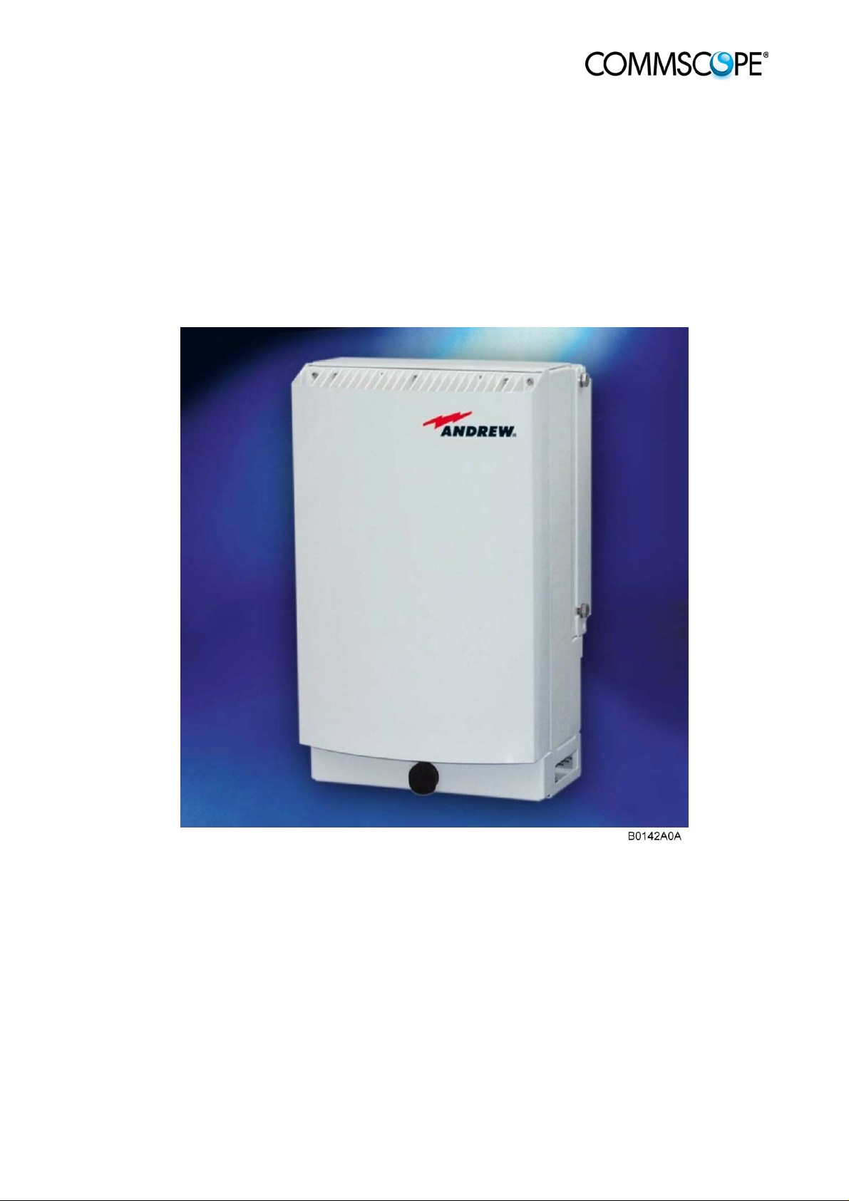
Extension Unit
ION™-M17P/26 EU
(Q-cabinet)
User's Manual
MF0133AUA

© Copyright 2011 CommScope, Inc.
All rights reserved.
User’s Manual for
ION™-M17P/26 EU
Andrew Solutions is a trademark of CommScope, Inc.
All information contained in this manual has been revised thoroughly. Yet Andrew
Solutions accepts no liability for any omissions or faults.
Andrew Solutions reserves the right to change all hard- and software characteristics
without notice.
Names of products mentioned herein are used for identification purposes only and
may be trademarks and / or registered trademarks of their respective companies.
No parts of this publication may be reproduced, stored in a retrieval system,
transmitted in any form or by any means, electronical, mechanical photocopying,
recording or otherwise, without prior written permission of the publisher.
Andrew Wireless Systems GmbH, 17-November -2011
Page 2 Manual MF0133AUA.doc

TABLE OF CONTENTS
1. GENERAL 5
1.1. USED ABBREVIATIONS 5
1.2. HEALTH AND SAFETY WARNINGS 6
1.3. ABOUT ANDREW SOLUTIONS 8
1.4. INTERNATIONAL CONTACT ADDRESSES FOR CUSTOMER SUPPORT 9
2. FUNCTIONAL DESCRIPTION 11
2.1. PURPOSE 11
2.2. THE ION-M17P/26 EU 11
2.3. THE ION-M26 EU (STANDALONE VERSION) - FOR WIMAX 12
3. COMMISSIONING 14
3.1. MECHANICAL INSTALLATION 14
3.1.1. General 14
3.1.2. Wall and Pole Mounting 15
3.2. ELECTRICAL INSTALLATION 16
3.2.1. General 16
3.2.2. Connections 17
3.2.3. Grounding 17
3.2.4. Connection to the Main Unit 18
3.2.5. Connection of RF Cables to Combining Unit 18
3.2.6. Power Connection 19
3.3. COMMISSIONING 20
4. ALARMS 24
4.1. BITE AND ALARMS 24
4.2. HANDLING OF ALARMS 24
4.3. ALARM STATUS 24
4.4. TROUBLESHOOTING 25
5. MAINTENANCE 26
5.1. OPENING AND CLOSING OF THE CABINET 27
5.2. REPLACEMENT OF POWER SUPPLY 28
Page 3

User’s Manual for
ION™-M17P/26 EU
5.3. REPLACEMENT OF FAN UNIT 29
5.4. SPECIFICATIONS 30
5.4.1. Electrical Specifications of ION-M17P EU 30
5.4.2. Electrical Specifications of ION-M26 EU 30
5.4.3. Mechanical Specifications of ION-M17P/26EU 30
5.4.4. Environmental and Safety Specifications of ION-M17P/26EU 31
5.5. SPARE PARTS LIST 31
6. INDEX 32
FIGURES AND TABLES
figure 3-1 Wall mounting........................................................................................... 15
figure 3-2 Pole mounting .......................................................................................... 15
figure 3-3 ION-M17P/26 EU, connector flange, exemplary....................................... 17
figure 3-4 Grounding bolt.......................................................................................... 17
figure 3-5 AC mains plug.......................................................................................... 19
figure 3-6 DC mains plug.......................................................................................... 19
figure 5-1 Locker with key......................................................................................... 27
figure 5-2 Front and top cover screws...................................................................... 27
figure 5-3 Power supply screws................................................................................ 28
figure 5-4 Fan unit screws ........................................................................................ 29
figure 5-5 Fan-connector cable................................................................................. 29
table 1-1 List of international contact addresses....................................................... 10
table 4-1 Status LED alarms..................................................................................... 25
table 5-1 Specified torques for various screw types ................................................. 26
Page 4 Manual MF0133AUA.doc

1. GENERAL
1.1. USED ABBREVIATIONS
3GPP 3rd Generation Partnership Project
AC/DC Alternating current / Direct Current
AIMOS Andrew Integrated Management and Operating System
ALC Automatic Level Control
BITE Built-In Test Equipment
BTS Base Transceiver Station
CE "Conformité Européenne" ("European Conformity")
CD Compact Disk
CPD Channel Power Detection
DL Downlink
DoC Declaration of Conformity
EDGE Enhanced Data Rates for GSM Evolution
EN European Norm
EP Extension Port
ESD Electrostatic Discharge
ETS European Telecommunication Standard
EU Extension Unit
GSM Global System for Mobile Communication
GND Ground
GUI Graphical User Interface
ICP3 Intercept Point 3
ID No Identification Number
ION Intelligent Optical Network
IP Ingress Protection
ISO International Organization for Standardization
LED Light Emitting Diode
LMT Local Maintenance Terminal
LTE Long Term Evolution
MIMO Multiple Input Multiple Output
MS Mobile Station
MU Main Unit
NF Noise Figure
OTRx Optical Transceiver = SRMU (Subrack Master Unit)
PDU Power Distribution Unit
PG Packing Gland
PIM Passive Intermodulation
R&TTE Radio & Telecommunications Terminal Equipment
Rev Revision
RF Radio Frequency
RU Remote Unit
RX Receiver
SNMP Simple Network Management Protocol
TS Technical Specification
TX Transmitter
UL Uplink
UMTS Universal Mobile Telecommunication System
UPS Uninterruptible Power Supply
VSWR Voltage Standing Wave Ratio
WCDMA Wideband Code Division Multiple Access
WDM Wavelength Division Multiplex
rd
order

1.2. HEALTH AND SAFETY WARNINGS
1. Only suitably qualified personnel is allowed to work on this unit and only after
becoming familiar with all safety notices, installation, operation and maintenance
procedures contained in this manual.
2. Read and obey all the warning labels attached to the unit. Make sure that the
warning labels are kept in a legible condition and replace any missing or
damaged labels.
3. Obey all general and regional installation and safety regulations relating to work
on high voltage installations, as well as regulations covering correct use of tools
and personal protective equipment.
4. Keep operating instructions within easy reach and make them available to all
users.
5. It is the responsibility of the network provider to implement prevention measures
to avoid health hazards which may be associated to radiation from the antenna(s)
connected to the unit.
6. Note for a Class A digital device or peripheral:
This equipment has been tested and found to comply with the limits for a
Class A digital device, pursuant to part 15 of the FCC Rules. These limits
are designed to provide reasonable protection against harmful interference
when the equipment is operated in a commercial environment. This
equipment generates, uses, and can radiate radio frequency energy and, if
not installed and used in accordance with the instruction manual, may
cause harmful interference to radio communications. Operation of this
equipment in a residential area is likely to cause harmful interference in
which case the user will be required to correct the interference at his own
expense.
7. Make sure, access is restricted to qualified personnel.
8. Only licence holders for the respective frequency range are allowed to operate
this unit.
9. Corresponding local particularities and regulations must be observed. For national
deviations please refer to the respective documents included in the manual CD
delivered.
10. Use this equipment only for the purpose specified by the manufacturer. Do not
carry out any modifications or fit any spare parts which are not sold or
recommended by the manufacturer. This could cause fires, electric shock or other
injuries.
11. Due to power dissipation, the repeater may reach a very high temperature. Do not
operate this equipment on or close to flammable materials.
Page 6 Manual MF0133AUA.doc

12. Before opening the unit, disconnect mains.
13. ESD precautions must be observed! Before commencing maintenance work, use
the available grounding system to connect ESD protection measures.
14. This unit complies with European standard EN60950.
15. Make sure the repeater settings are according to the intended use (see also
product information of manufacturer) and regulatory requirements are met.
16. Although the repeater is internally protected against overvoltage, it is strongly
recommended to earth the antenna cables close to the repeater’s antenna
connectors for protection against atmospheric discharge.
17. Laser radiation! Do not stare into the beam; do not view it directly or with optical
instruments.

1.3. ABOUT ANDREW SOLUTIONS
Andrew Wireless Systems GmbH based in Buchdorf / Germany, is a leading
manufacturer of coverage equipment for mobile radio networks, specializing in high
performance, RF and optical repeaters. Our optical distributed networks and RF
repeater systems provide coverage for every application: outdoor use, indoor
installations, tunnels, subways and many more.
Andrew Wireless Systems GmbH has unparalleled experience in providing RF
coverage and capacity solution for wireless networks in both indoor and outdoor
environment and belongs to Andrew Solutions, a CommScope Company.
Andrew Solutions is the foremost supplier of one-stop, end-to-end radio frequency
(RF) solutions. Our products are complete solutions for wireless infrastructure from
top-of-the-tower base station antennas to cable systems and cabinets, RF site
solutions, signal distribution, and network optimization.
Andrew Solutions has global engineering and manufacturing facilities. In addition, it
maintains field engineering offices throughout the world.
We operate a quality management system in compliance with the requirements of
ISO 9001. All equipment is manufactured using highly reliable material. In order to
ensure constant first-rate quality of the products, comprehensive quality monitoring is
conducted at all fabrication stages. Finished products leave the factory only after a
thorough final acceptance test, accompanied by a test certificate guaranteeing
optimal operation.
Note: Exceptions of and national deviations from this intended use may be
possible. To observe corresponding local particularities and
regulations, please refer to the respective documents (also in
national language) which are included in the manual CD delivered.
To make the most of this product, we recommend you carefully read the instructions
in this manual and commission the system only according to these instructions.
For technical assistance and support, please also contact the local office or Andrew
Solutions directly at one of the addresses listed in the following section.
Page 8 Manual MF0133AUA.doc

1.4. INTERNATIONAL CONTACT ADDRESSES FOR CUSTOMER SUPPORT
Americas:
Canada United States
Andrew Solutions Canada
620 North Greenfield Parkway
Mail
Phone
Fax +1-905-878-3297 Fax +1-919-329-8950
E-mail
Mail
Phone + 55-15-9104-7722 Phone
Fax + 55-15-2102-4001 Fax +52-55-1346-1901
E-mail WIsupport@commscope.com
Garner, NC 27529
U.S.A.
+1-905-878-3457 (Office)
+1-416-721-5058 (Mobile)
Peter.Masih@commscope.com,
WIsupport.us@commscope.com
Brazil & South America
CommScope Cabos do Brasil Ltda.
Av. Com. Camilo Julio 1256
Zonal Industrial CP 597
Sorocaba SP 18086-000
Brazil
Andrew LLC, A CommScope Company
Mail
Phone +1-888-297-6433
E-mail WIsupport.us@commscope.com
Mail
E-mail WIsupport@commscope.com
Andrew Solutions,
620 North Greenfield Parkway
Garner, NC 27529
U.S.A.
Mexico, Central America &
Caribbean region
Andrew Corporation Mexico,
SA DE CV
Av. Insurgentes Sur 688, Piso 6
Col. Del Valle, CP: 03100
Mexico City
Mexico
+52-55-1346-1900 (Office)
+52-1-55-5419-5260 (Mobile)
APAC Countries:
China, India and Rest of Asia Australia & New Zealand
Andrew International Corporation Andrew Corporation (Australia) Pty Ltd.
Room 915, 9/F
Chevalier Commercial Centre
Mail
Phone +852-3106-6100 Phone +613-9300-7969
Fax +852-2751-7800 Fax +613-9357-9110
E-mail WIsupport.China@commscope.com
8 Wang Hoi Rd
Kowloon Bay
Hong Kong
Mail
E-mail WIsupport.Australia@commscope.com
Unit 1
153 Barry Road
Campbellfield
VIC 3061
Australia

Europe:
United Kingdom France
Andrew Solutions UK Ltd CommScope France
Unit 15, Ilex Building
Mulberry Business Park
Mail
Phone +44-1189-366-792 Phone
Fax +44-1189-366-773 Fax
E-mail WIsupport.uk@commscope.com
Mail
Phone +49-9099-69-0 Phone +420-464-6280-80
Fax +49-9099-69-930 Fax +420-464-6280-94
Fishponds Road
Wokingham Berkshire
RG41 2GY
England
Germany Czech Republic
Andrew Wireless Systems GmbH
Industriering 10
86675 Buchdorf
Germany
Mail
E-mail WIsupport@commscope.com
Mail
Immeuble Le Lavoisier
4, Place des Vosges
92052 Courbevoie
France
+33-1 82 97 04 00
+33-1 47 89 45 25
Andrew Solutions Czech Republic
C-Com, spol. s r.o
U Moruší 888
53006 Pardubice
Czech Republic
E-mail WIsupport@commscope.com
Austria Switzerland
Andrew Wireless Systems (Austria) GmbH Andrew Wireless Systems AG
Weglgasse 10
Mail
Phone +43-1706-39-99-10 Phone +41-62-386-1260
Fax +43-1706-39-99-9 Fax +41-62-386-1261
E-mail WIsupport.austria@commscope.com
Mail
Phone +39-0546-697111 Phone +34-91-745-20 40
Fax +39-0546-682768 Fax +34-91-661-87 02
E-mail WIsupport.italia@commscope.com
2320 Wien-Schwechat
Austria
Italy Spain and Portugal
Commscope Italy S.r.l., Faenza, Italy
Via Mengolina, 20
48018 Faenza (RA)
Italy
E-mail WIsupport@commscope.com
Tiergartenweg 1
Mail
E-mail WIsupport.ch@commscope.com
Mail
E-mail WIsupport.iberia@commscope.com
CH-4710 Balsthal
Switzerland
Andrew Solutions España S.A.
A Commscope Company
Avda. de Europa, 4 - 2ª pta.
Parque Empresarial La Moraleja
28108 Alcobendas (Madrid)
Spain
table 1-1 List of international contact addresses
Page 10 Manual MF0133AUA.doc
 Loading...