

®
ION
-E
Series
User's Manual
M0201A0A
PRELIMINARY

DISCLAIMER:
This document has been developed by CommScope, and is intended for the use of its customers and customer
support personnel. The information in this document is subject to change without notice. While every effort has been
made to eliminate errors, CommScope disclaims liability for any difficulties arising from the interpretation of the
information contained herein. The information contained herein does not claim to cover all details or variations in
equipment, nor to provide for every possible incident to be met in connec
tion with installation, operation, or
maintenance. This document describes the performance of the product under the defined operational conditions and
does not cover the performance under adverse or disturbed conditions. Should further information be desired, or
should particular problems arise which are not covered sufficiently for the purchaser’s purposes, contact CommScope.
CommScope reserves the right to change all hardware and software characteristics without notice.
COPYRIGHT:
© Copyright 2014 CommScope Inc. All Rights Reserved.
This document is protected by copyright. No part of this document may be reproduced, stored in a retrieval system, or
transmitted, in any form or by any means, electronic, mechanical photocopying, recording, or otherwise without the
prior written permission of CommScope.
For patents see www.cs-pat.com
.
TRADEMARKS
All trademarks identified by ® or ™ are registered trademarks or trademarks, respectively, of CommScope. Names of
products mentioned herein are used for identification purposes only and may be trademarks and / or registered
trademarks of their respective companies.
Andrew Wireless Systems GmbH, 09-February-2015
1. General
1.1. DCCS Technical Support
For technical assistance and support, please contact the DCCS technical support team.
Email: wisupport@commscope.com
+1 888-297-6433 in North and South America and +49 9099-69-333 in Europe, Middle East and Asia
1.2. Equipment Symbols Used / Compliance
Please observe the meanings of the following symbols used in this equipment:
Symbol Compliance Meaning
--- FCC
CE
WARNING: This is NOT a CONSUMER device. It is designed for installation by FCC LICENSEES and
QUALIFIED INSTALLERS. You MUST have an FCC LICENSE or express consent of an FCC Licensee to
operate this device. Unauthorized use may result in significant forfeiture penalties, including penalties in
excess of $100,000 for each continuing violation.
You MUST register Class B signal boosters (as defined in 47 CFR 90.219) online at www.fcc.gov/signalboosters/registration.
Alert sign to R&TTE
To be sold exclusively to mobile operators or authorized installers – no harmonised frequency bands,
operation requires license
Intended use: EU and EFTA countries
Indicates conformity with the R&TTE directive 1999/5/EC certified by the notified body no. 0700.
Page 2
M0201A0A_uc User’s Manual for ION®-E
1.3. Health and Safety
1. Warning: A High leakage current ground (earth) connection
to the power supply subrack is essential before connecting
the supply.
2. Caution: Laser radiation. Risk of eye injury in operation. Do
not stare into the beam; do not view it directly or with optical
instruments.
3. Caution: High frequency radiation in operation. Risk of
health hazards associated with radiation from the antenna(s)
connected to the unit. Implement prevention measures to
avoid the possibility of close proximity to the antenna(s)
while in operation.
1.4. Property Damage Warnings
1. Attention: Due to power dissipation, the power supply units
may reach a very high temperature if not properly ventilated.
Do not operate this equipment on or close to flammable
materials.
2. Notice: ESD precautions must be observed. Before
commencing maintenance work, use the available grounding
(earthing) system to connect ESD protection measures.
3. Notice: Keep operating instructions within easy reach and
make them available to all users.
4. Notice: Only license holders for the respective frequency
range are allowed to operate this unit.
5. Notice: Read and obey all the warning labels attached to
the unit. Make sure that all warning labels are kept in a
legible condition. Replace any missing or damaged labels.
6. Notice: Make sure the unit’s settings are correct for the
intended use (refer to the manufacturer product information)
and regulatory requirements are met. Do not carry out any
modifications or fit any spare parts, which are not sold or
recommended by the manufacturer.
1.5. Compliance
1. Warning! This is class A equipment. This equipment can
cause radio interference in domestic areas. In this case the
operator can be asked to start preventive action.
2. Notice: For installations, which have to comply with FCC RF
exposure requirements, the antenna selection and
installation must be completed in a way to ensure
compliance with those FCC requirements. Depending on the
RF frequency, rated output power, antenna gain, and the
loss between the repeater and antenna, the minimum
distance D to be maintained between the antenna location
and human beings is calculated according to this formula:
P
[ mW
]
D
=
[
cm]
4
∗π ∗
PD
[
mW / cm
2
]
where
• P (mW) is the radiated power at the antenna, i.e. the
max. rated repeater output power in addition to the
antenna gain minus the loss between the repeater and
the antenna.
a. PD (mW/cm²) is the allowed Power Density limit acc.
to 47 CFR 1.1310 (B) for general population /
uncontrolled exposures which is
o F (MHz) / 1500 for frequencies from 300MHz to
1500MHz
o 1 for frequencies from 1500MHz to 100,000MHz
RF exposure compliance may need to be addressed at the
time of licensing, as required by the responsible FCC
Bureau(s), including antenna co-location requirements of
1.1307(b)(3).
M0201A0A_uc User’s Manual for ION
®
-E Page 3
1.
3. Notice: For installations which have to comply with
European EN50385 exposure compliance requirements, the
following Power Density limits/guidelines (W/M²) according
to ICNIRP are valid:
a. 2 for frequencies from 10 MHz to 400 MHz
b. F (MHz) / 2000 for frequencies from 400 MHz to 2 GHz
c. 10 for frequencies from 2 GHz to 300 GHz
4. Notice: Notice: For installations which have to comply with
FCC/Industry Canada requirements:
English
This device complies with FCC Part 15. Operation is subject
to the following two conditions: (1) this device may not cause
interference, and (2) this device must accept any
interference, including interference that may cause
undesired operation of the device.
This device complies with Health Canada’s Safety Code.
The installer of this device should ensure that RF radiation is
not emitted in excess of the Health Canada’s requirement.
Information can be obtained at http:
//www.hc-sc.gc.ca/ewh-semt/pubs/radiation/radio_guidelignes_direct-eng.php.
Changes or modifications not expressly approved by the
party responsible for compliance could void the user’s
authority to operate the equipment.
The antenna(s) used for this transmitter must be installed to
provide a separation distance of at least 20 cm from all
persons and must not be co-located or operating in
conjunction with any other antenna or transmitter.
French
Cet appareil est conforme à FCC Partie15. Son utilisation
est soumise à Les deux conditions suivantes: (1) cet
appareil ne peut pas provoquer d’interférences et (2) cet
appareil doit accepter Toute interférence, y compris les
interférences qui peuvent causer un mauvais
fonctionnement du dispositif.
Cet appareil est conforme avec Santé Canada Code de
sécurité 6. Le programme d’installation de cet appareil doit
s’assurer que les rayonnements RF n’est pas émis au-delà
de I’exigence de Santé Canada. Les informations peuvent
être obtenues:
http://www.hc-sc.gc.ca/ewhsemt/pubs/radiation/radio_guide-lignes_direct-fra.php
Les changements ou modifications non expressément
approuvés par la partie responsable de la conformité
pourraient annuler l'autorité de l'utilisateur à utiliser cet
équipement.
La ou les antennes utilisées avec cet émetteur doivent être
installées avec une séparation d’au minimum 20cm avec
toute personne et ne doivent pas être co-localisées ou
utilisées avec toute autre antenne ou tout autre émetteur.
5. Notice: Corresponding local particularities and regulations
must be observed. For national deviations, please refer to
the respective documents included in the manual CD that is
delivered with the unit.
General
6. Note: For a Class A digital device or peripheral:
This equipment has been tested and found to comply with
the limits for a Class A digital device, pursuant to EN55022
and part 15 of the FCC Rules. These limits are designed to
provide reasonable protection against harmful interference
when the equipment is operated in a commercial
environment.
2. ION-E System
This equipment generates, uses, and can radiate radio
frequency energy and, if not installed and used in
accordance with the instruction manual, may cause harmful
interference to radio communications. Operation of this
equipment in a residential area is likely to cause harmful
interference in which case the user will be required to
correct the interference at his own expense.
7. Note: This unit complies with European standard EN60950.
Overview
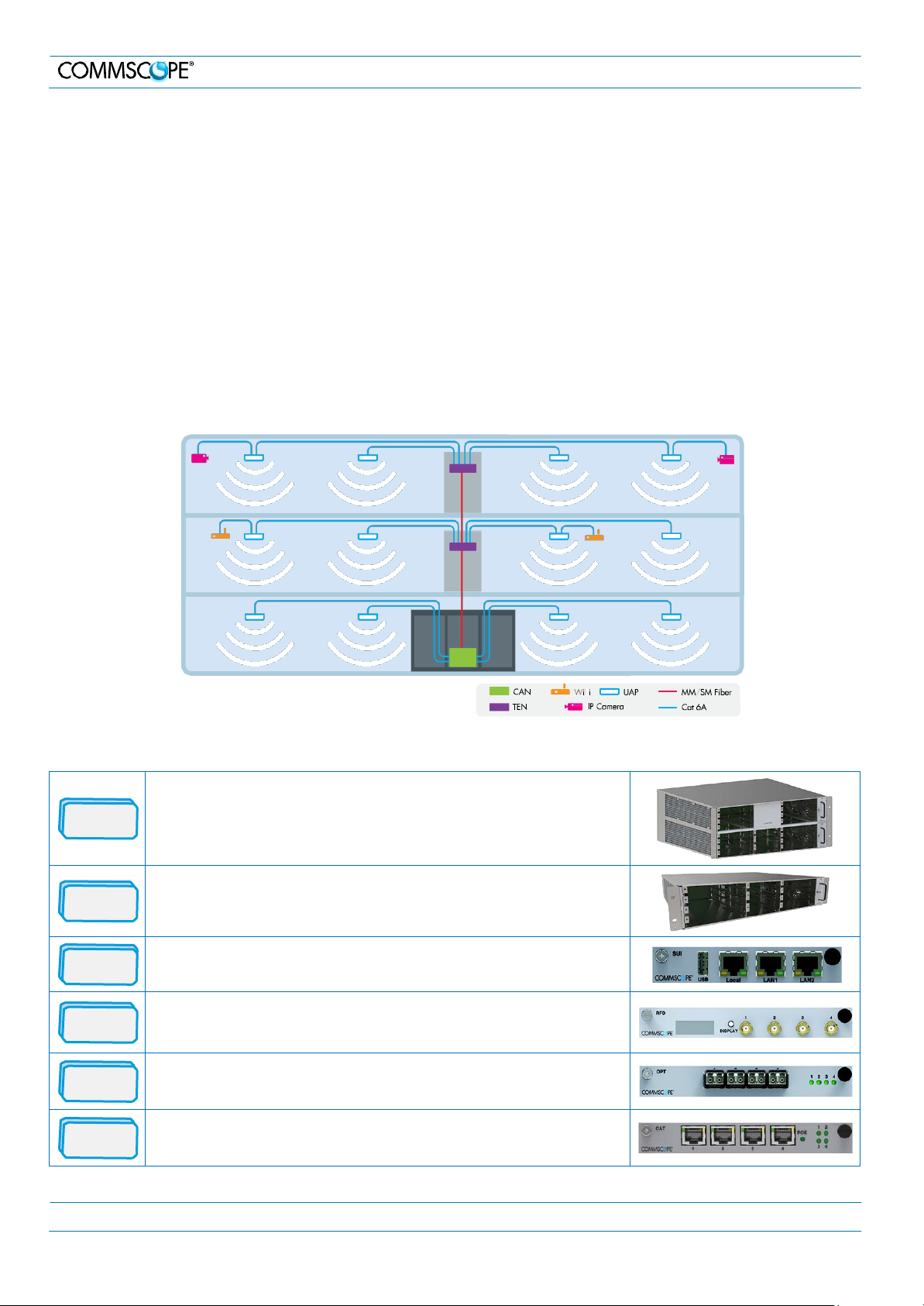
2. ION-E System Overview
The ION-E is a unified wireless infrastructure platform defined around IT based architecture. It brings together licensed wireless
and power, plus Gigabit Ethernet for Wi-Fi into one wireless network that can scale to building size and is technology and spectrum
agnostic and adaptive.
• Central Area Node (CAN): Server-level control and primary signal distribution. 2U and 4U subrack options are available.
• Transport Expansion Node (TEN): The secondary distribution point connected to a CAN using multimode or single mode
fiber.
• Universal Access Point (UAP): data and power through Category 6A twisted pair cabling. Supports gigabit Ethernet for
WiFi, IP cameras, or other devices in addition to wireless over a common cable.
2.1. ION-E Components Overview
WCS-4
The WCS-4 is a 4U subrack. It is typically used as a CAN but can also
serve as a TEN.
WCS-2
The WCS-2 is a 2U subrack. It is typically used as a TEN, but can also
serve as a CAN.
SUI
RFD
OPT
CAT
The System User Interface card provides local and LAN Ethernet
connections and a USB port.
The RF Donor card is the interface for RF signals between the CAN and
the BTS or eNode-B. Each of its four ports (QMA F) simultaneously
transmits and receives signals.
The OPtical Transport card provides a 10 Gb fiber connection between a
CAN and a TEN. Each card supports up to four SFP+ modules.
The Copper Transport card provides 10 Gb Cat6A connections between
the CAN or TEN and the UAP. The cards also supply the PoE to the UAPs.
M0201A0A_uc User’s Manual for ION®-E Page 4
Metal C
ab
i
ne
t
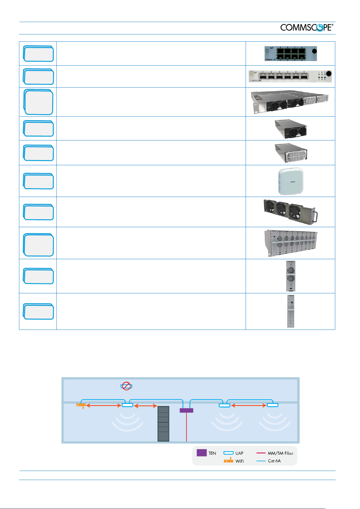
2. ION-E System Overview
The Auxiliary Unit Transport card provides a 1 Gb pass-through
AUT
connection between the CAN or TEN and the UAP for Wi-Fi, IP cameras,
or other 1 Gb Ethernet devices.
BIT
Power
Supply
Subrack
12 VDC
57 VDC
UAP
FAN
e-POI
Subrack
The Baseband Interface Transceiver card provides the fiber interface to
BBU ports. Up to six BBU port connections per card are supported.
The Power Supply subrack houses two 12 Vdc and two 57 Vdc modules to
supply power to the WCS subracks, UAPs, and connected devices.
The 12 Vdc modules plug into the power supply subrack to provide 12 Vdc
power to the WCS and e-POI subracks.
The 57 Vdc modules plug into the power supply subrack to provide 57 Vdc
power for the UAP and other PoE devices connected to a WCS subrack.
The Universal Access Point broadcasts up to 300 MHz of RF spectrum in
four bands. Plus it has a gigabit Ethernet port for ancillary devices.
The Fan tray and Filter modules cool the WCS and all of its cards. One fan
tray is used for a WCS-2. Two trays are used for a WCS-4.
The e-POI subrack supports up to 8 e-POI modules and an IFC module.
e-POI
IFC
The e-POI (Point of Interface) card is a low PIM attenuator. It reduces high
power RF signals from their source by 30 dB to interface to the RFD cards.
The IFC (Interface Card) is used to set the subrack number of the e-POI
subrack. It also provides a status LED for each of the e-POI modules in the
subrack.
2.2. UAP Ceiling Mounting
The UAP is equipped with a grounding screw located in the center of the unit, however, grounding is not required as UAPs are
classified as low-voltage devices and do not have internal power supplies. CommScope recommends checking your local and
national electrical codes to determine if grounding is a requirement.
WiFi
3m min
Install below ceiling grid
2m min
only
Collocated
UAPs (MIMO)
3m min
M0201A0A_uc User’s Manual for ION®-E Page 5
 Loading...