

Andrew Wireless Innovations Group BCEL-800-900 Users Manual
27. Installation and cabling
27.1. Location
The TPR sub-rack should be placed as near as possible the BTS or the RF repeater.
The sub-rack location should be easy to reach by the users in order to allow alarm
monitoring.
WARNING! do not close the air circulation subrack grids (top and bottom) with
9
panels or obstacles.
If the subrack mounting location does not have a good air circulation, leave at
9
least one unit (1HE) free between subracks.
27.2. Power supply
The connection to the mains has to be carried out following all the necessary
precautions, including the following:
• in accordance with diligence rules (ex. CEI rules, IEC rules, etc.);
• in accordance with the rules for the safety against direct or indirect contacts;
• in accordance with the rules for the safety against over current (short circuit,
overloading);
• in accordance with the rules for the safety against the over tension;
• the connection is to be carried out by properly trained technicians.
27.2.1. Universal mains
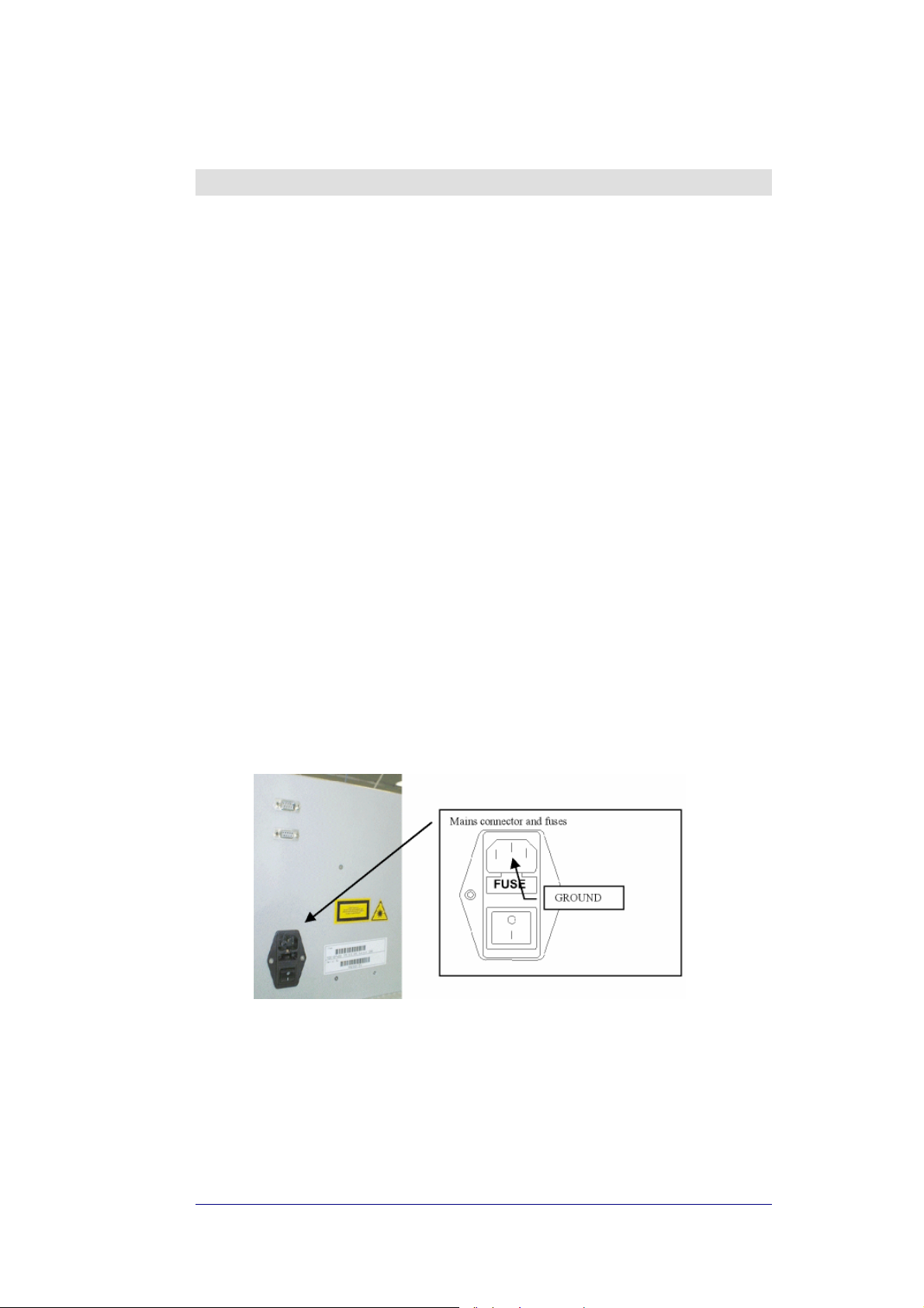
Universal main (85-264VAC, 50/60Hz) apply to TPR912 model only. Mains
connector is placed on the back panel (see Fig. 26 mains connector)
Fig. 26 mains connector
The TPR912 model has an internal AC/DC converter. With 220VAC power supply
the efficiency is 75%. Each TFA has a power consumption of 12W, therefore a fully
equipped configuration (6 TFLs) requires (12W x 6) / 0.75 = 96W.
This formula is helpful in verifying the overall power consumption.
BRITECELL System Manual MN010-04 June 2003 Page 40 of 78
The company has a policy of continuous product development and improvement and we therefore
reserve the right to vary any information quoted without prior notice.
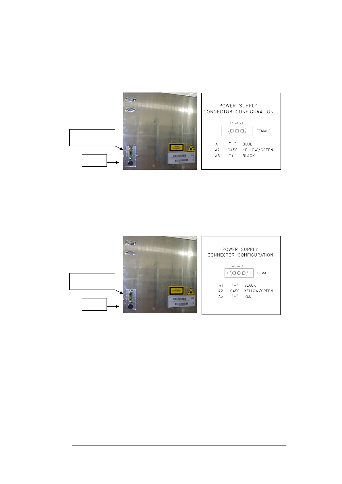
27.2.2. DC negative supply
Direct current ( –72 to –36 VDC) apply to TPR922 model only. Power connector is
placed on the back panel (see
Fig. 27 VDC Connector (TPR922 only))
MALE POWER
CONNECTOR
FUSE
Fig. 27 VDC Connector (TPR922 only)
TPR922 model has an internal DC/DC converter: power consumption is the same
as above.
Direct current (16 to 24 VDC) to be applied to TPR932 model only. Power
connector is placed on the back panel (see Fig. 28 VDC Connector (TPR932 only))
MALE POWER
CONNECTOR
FUSE
Fig. 28 VDC Connector (TPR932 only)
TPR932 model has an internal DC/DC converter: power consumption is the same
as above.
BRITECELL System Manual MN010-04 June 2003 Page 41 of 78
The company has a policy of continuous product development and improvement and we therefore
reserve the right to vary any information quoted without prior notice.
27.2.3. Grounding
Ground terminals are part of power supply connectors, as showed in previous
figures (Fig. 26 mains connector, Fig. 27 VDC Connector (TPR922 only), Fig. 28
VDC Connector (TPR932 only)).
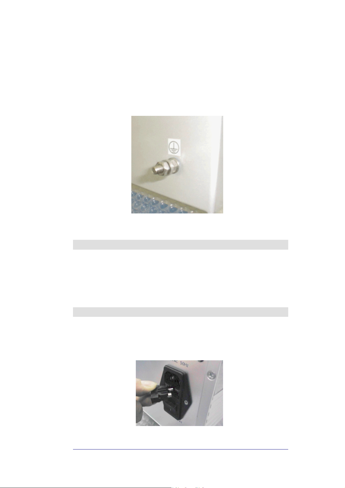
An external grounding terminal, with screw, is available at the back panel (see Fig.
29 ground)
Fig. 29 ground
28. Start up
WARNING: Verify voltage levels before connecting and powering on the
9
subrack
Please refer to system start-up section for further details.
29. Troubleshooting
The way a fuse is changed depends on the subrack version (refer to the
datasheet). One or two fuses are present on the back of the rack, which needs to
be replaced when they fail
BRITECELL System Manual MN010-04 June 2003 Page 42 of 78
The company has a policy of continuous product development and improvement and we therefore
reserve the right to vary any information quoted without prior notice.
Fig. 30 fuse

TFL-BSI RF attenuator
30. Introduction
This section describes the TFL-BSI (Base Station Interface). The TFL-BSI is part of
the Britecell system and allows the operator to optimise the signal level the BTS or
repeater and the Britecell system. It includes two independent variable attenuators
(30 dB, one dB step) for uplink and downlink RF path.
A single attenuator version is available, for downlink only or uplink only operations.
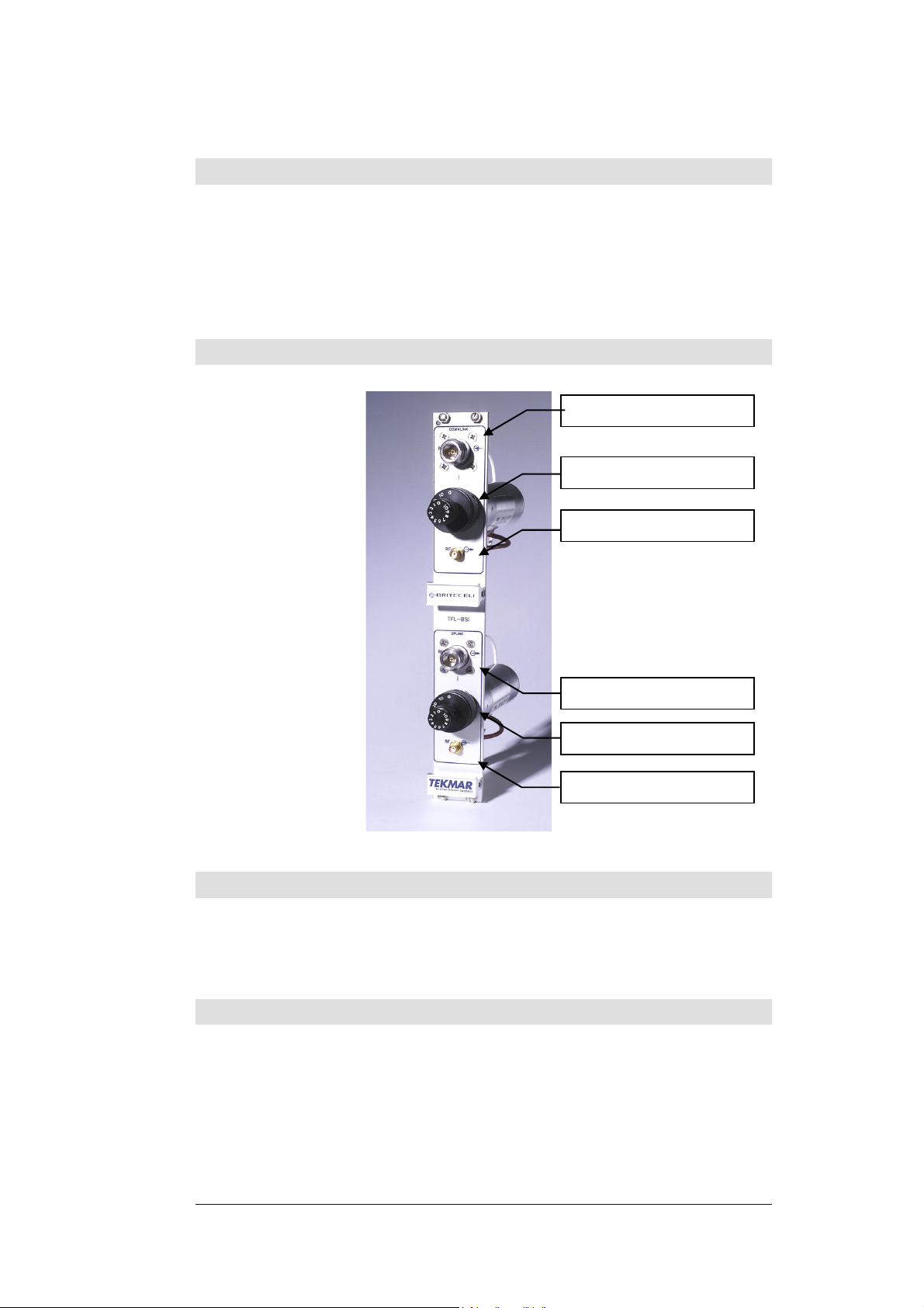
31. Part description
Fig. 31 - TFLBSI
Downlink RF input (from BTS)
Downlink attenuation settings
Downlink RF output (to TFL)
Uplink RF output (to BTS)
Uplink attenuation settings
Uplink RF input (from TFL)
32. Warnings
9
Maximum RF composite input power must not exceed 30 dBm.
9
SMA connectors must be screwed with a proper dynamometric key.
33. Functional description
33.1. Down link operation
If the RF signal coming from the BTS or repeater in downlink path has a power
level, which is not adequate to the TFL’s characteristics, an attenuator is required.
BRITECELL System Manual MN010-04 June 2003 Page 44 of 78
The company has a policy of continuous product development and improvement and we therefore
reserve the right to vary any information quoted without prior notice.

33.2. Uplink operation
The RF signal coming from the mobile through the TFA and TFL in the uplink
direction may not be an optimal level. When this is the case, the uplink attenuator
is used to prevent the BTS from being over driven.
34. Installation and cabling
34.1. TPR housing
The TFL-BSI is a modular plug-in card designed to be put in a 6 HE sub-rack (TPR
family).
The TFL-BSI interfaces with the BTS transmitter and receiver through N-female
connectors and with Britecell with SMA-female connectors.
The connection with the BTS may be direct, if the BTS’s transmitter and receiver
are separated, or through a circulator or a common path RF combiner (please refer
also to THYB section).
When the system is air interfaced through a repeater a common path RF combiner
is required in order to separate the uplink and downlink path.
The connection between TFL-BSI and Local Units may be direct or through a
combiner stage (please refer to TLC section) depending on the system’s
configuration.
35. Calculation of attenuation setting
35.1. Downlink
Calculation of Downlink TFL-BSI setting is made in order to supply Britecell Local
Unit with correct DL input power.
)(]dB[
PILILPA
−−−=
where:
P
IL
IL
P
@POI_Input
Dir.Coupler
Comb.Net
DL_BC_Max
[dBm/c]= RF power level per carrier at POI input:
[dB]= Directional coupler insertion loss (if present);
. [dB]= Combining Network insertion loss;
[dBm/c]= Max input power per carrier at Local Unit input.
35.2. Uplink
Calculation of Uplink TFL-BSI setting is made to meet BTS uplink blocking
requirements.
where:
P
LU_UL@Blocking
[dBm]= Local Unit output power when Remote Unit is at blocking
level (3 dB C/N degradation);
P
BTS@Blocking
[dBm]= BTS receiver blocking level;
SM = Safe margin (typically 3 dB).
)]([]dB[
BlockingBTSNetbCCpouplerDirBlockingULLUblkULBSI
@.om.@___
MaxBCDLNetbCCpouplerDirInputPOIDLBSI
__.om._@_
+−+−=
SMPILILPA
BRITECELL System Manual MN010-04 June 2003 Page 45 of 78
The company has a policy of continuous product development and improvement and we therefore
reserve the right to vary any information quoted without prior notice.

TLC RF combiner - splitter
36. Introduction
This section describes the TLC splitter/combiner. The TLC is part of Britecell
system and provides a family of 2-way and 3-way RF power combiners in order to
allow several local interface modules to be connected to common UL and DL RF
paths, for interfacing to the BTS.
All units have internal pads (one per path) to achieve predefined insertion loss.
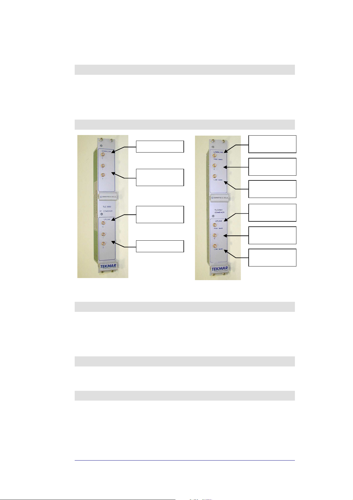
37. Part description
Downlink RF input
Downlink RF
splitted outputs
Uplink RF
combined output
Uplink RF inputs
Fig. 32 TLC2502 Fig. 33 TLC2501
Downlink RF
High Band input
Downlink RF
combined output
Downlink RF
Low Band input
Uplink RF
High Band output
Uplink RF
combined input
Uplink RF
Low Band output
38. Functional description
TLC2502/3 is a two/three way splitter for downlink path and combiner for uplink
path. For insertion loss values refer to datasheets.
TLC2501 is a crossband coupler, designed to combine or split hi-band signal and
low band signal in dual band systems. Insertion loss in this case is minimal (see
datasheets).
39. Warnings
9
Maximum RF composite input power must not exceed 24 dBm.
9
SMA connectors must be screwed with a proper dynamometric key.
40. Installation and cabling
40.1. TPR housing
The TLC is a modular plug-in card, suited to be contained in a 6 HE Sub rack (TPR
family).
The 2-way TLC module interfaces with the BTS transmitter and receiver through
TFL-BSI and with TFL Local Units directly or through 3-way splitter/combiner.
BRITECELL System Manual MN010-04 June 2003 Page 47 of 78
The company has a policy of continuous product development and improvement and we therefore
reserve the right to vary any information quoted without prior notice.

THYB common path RF
combiner
41. Introduction
This section describes the THYB common path RF combiner family. THYB is part of
Britecell system and it allows combining of downlink and uplink path into a single
one, while maintaining required isolation and stability.
This component has been designed for Britecell system configuration requiring
single RF connector carrying both DL and UL signals when system is interfaced
through a diplexed BTS.
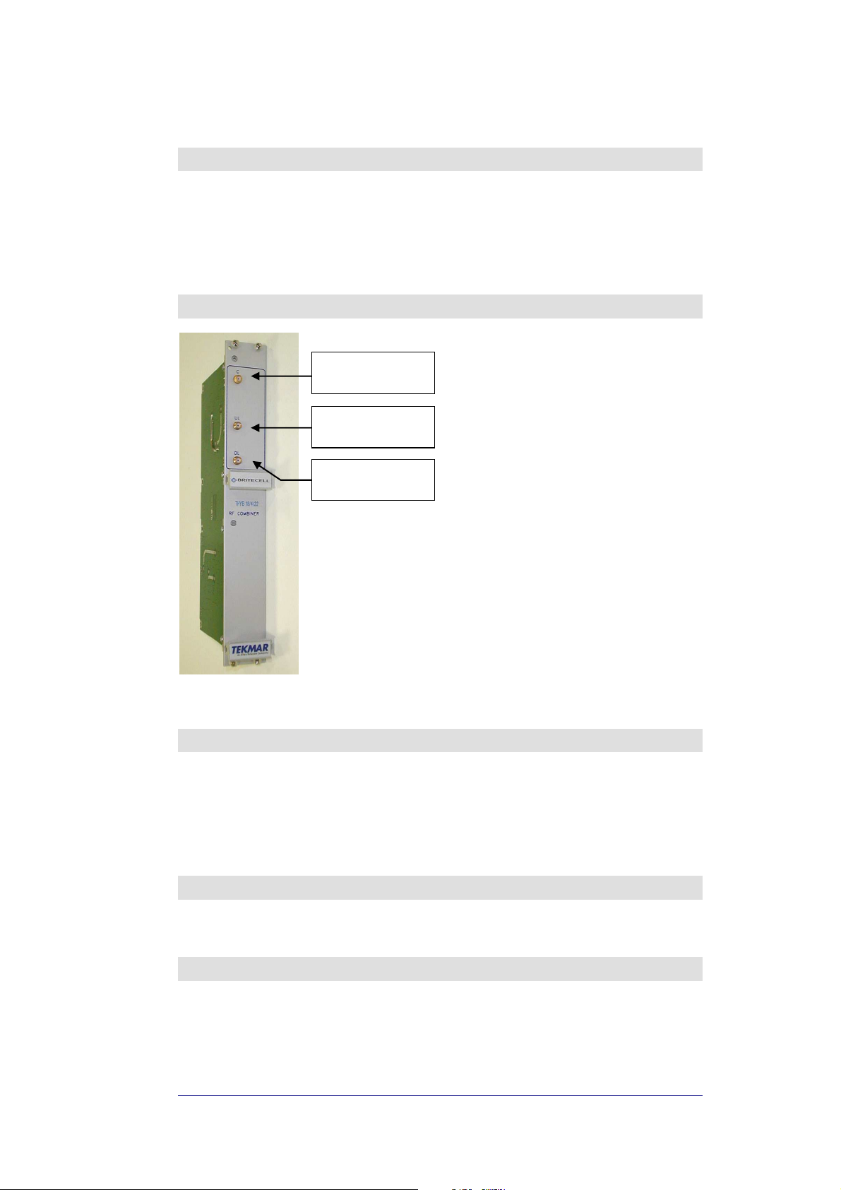
42. Part description
Fig. 34 THYB
DL/UL RF combined
input/output
Uplink RF
input
Downlink RF
output
43. Functional description
THYB is a bi-directional hybrid RF combiner/splitter. It can be chosen in single or
dual band version. It’s provided with uplink pass-band filters to improve UL
isolation performances.
THYB typical application is in conjunction with diplexed BTS where DL and UL
paths are provided in single RF connector.
For insertion loss value, refer to datasheets.
44. Warnings
9
Maximum RF composite input power must not exceed 30 dBm.
9
SMA connectors must be screwed with a proper dynamometric key.
45. Installation and cabling
THYB is a modular plug-in card, suited to be contained in a 6 HE Sub rack (TPR
family). THYB interfaces with BTS transceiver through ‘C’ connector (type SMAfemale). THYB interfaces with Britecell downlink and uplink paths through ‘DL’ and
‘UL’ connectors respectively (type SMA-female).
BRITECELL System Manual MN010-04 June 2003 Page 49 of 78
The company has a policy of continuous product development and improvement and we therefore
reserve the right to vary any information quoted without prior notice.

TFB booster
46. Introduction
The TFBxx is an optional part of the Britecell system and it’s intended to enhance
transmit power of Britecell remote transceivers TFA in order to maintain an output
power of 10 dBm per carrier when operating with up to 8 carriers.
Typical TFB configuration is together with TFA remote unit and TPA passive
antennae.
TFB is housed in the same metallic case as TFA and contains one amplifier for each
direction (uplink and downlink).
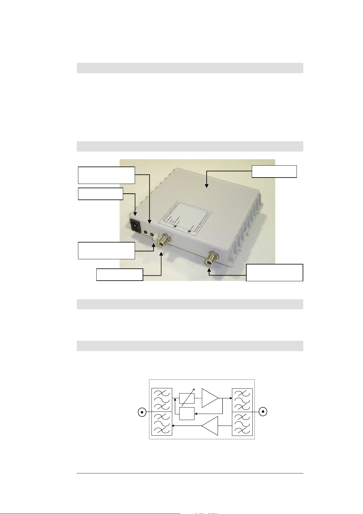
47. Part description
power on led (green)
alarm led (red)
power supply
alarm relay contact
(normally closed)
RF port to TFA
Fig. 35 TFB RF booster
warm side
RF port to
coverage antenna
48. Warnings
CAUTION! Do not connect the booster to TFA without first switching power
9
supply off.
49. Functional description
49.1. Block diagram
High Band Booster
TFA remote unit
Fig. 36 block diagram
BRITECELL System Manual MN010-04 June 2003 Page 51 of 78
The company has a policy of continuous product development and improvement and we therefore
reserve the right to vary any information quoted without prior notice.
ALC
AMP
AMP
TPA antenna
 Loading...