

22. Introduction
This section describes the TPR family (19” Sub rack). The TPR is part of the
Britecell system and host all plug-in modules such as TFL-card, TLC
splitter/combiner, TFL-BSI Base Station Interface and control modules.
A TPR sub-rack, when fully equipped, can support up to 6 TFL Local Units, one 2way splitter-combiner, two 3-way splitter-combiners, one Base Station Interface,
and one control module. Therefore this complete configuration supports up to 24
TFA Remote Units and up to 48 antennas.
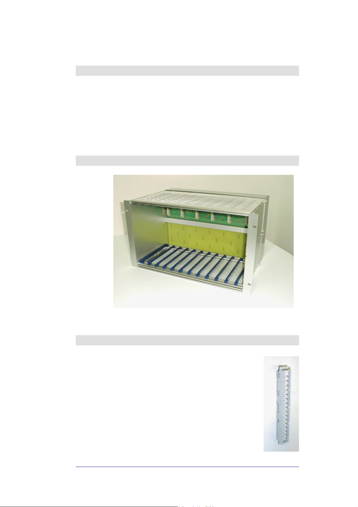
23. Part description
Fig. 22 TPR912
24. Warnings
Local interfaces may not be placed next to each other; one 7te
module is always required between them.
TFL local interface cards can only be fitted in slots 1, 3, 5, 7, 9,
and 11 of the sub-rack, slot 1 being the left most one.
WARNING: any slot capable of accepting an TFL that is
9
unused must be fitted with a dummy plug to avoid alarms
being generated (see Fig. 23)
WARNING: do not remove or insert any module into TPR
9
subrack, without switching the power supply off.
BRITECELL System Manual MN010-04 June 2003 Page 36 of 78
The company has a policy of continuous product development and improvement and we therefore
reserve the right to vary any information quoted without prior notice.
Fig. 23 - Dummy connector
25. Functional description
The TPR subrack provides:
• power supply to the active plug-in cards (12VDC);
• alarm logic and relays;
• mechanical housing and positioning.
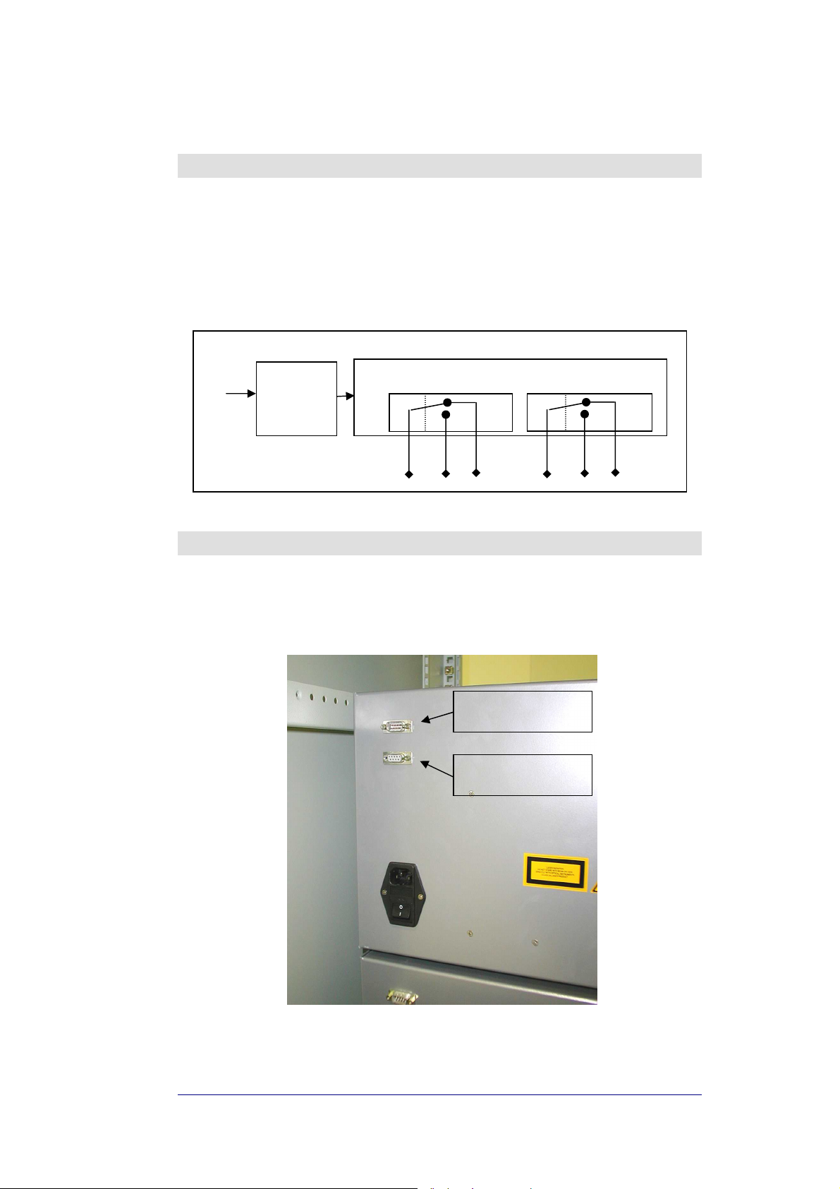
25.1. Block diagram
MAINS
AC/DC
or
DC/DC
converter
backplane, logic & relays
DL UL
Fig. 24 – TPR block diagram
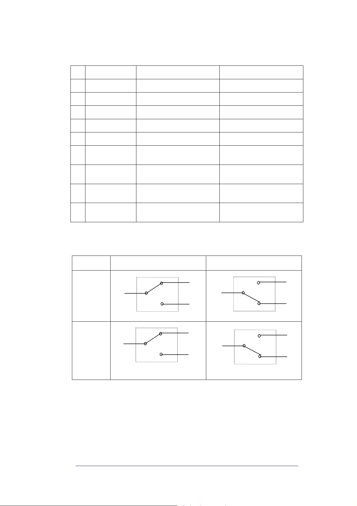
26. Alarms
The TPR sub-rack has a built-in alarm circuit: any fault in TFL or TFA causes a
contact relay close or open.
A sub-D 9 pins male connector at the back of the sub-rack gathers summary and
specific alarms of master/local subrack (see Tab. 6)
Fig. 25 alarm relay connector
Sub-D Male
Master sub-rack alarms
Sub-D Female
Slave sub-rack alarms
BRITECELL System Manual MN010-04 June 2003 Page 37 of 78
The company has a policy of continuous product development and improvement and we therefore
reserve the right to vary any information quoted without prior notice.
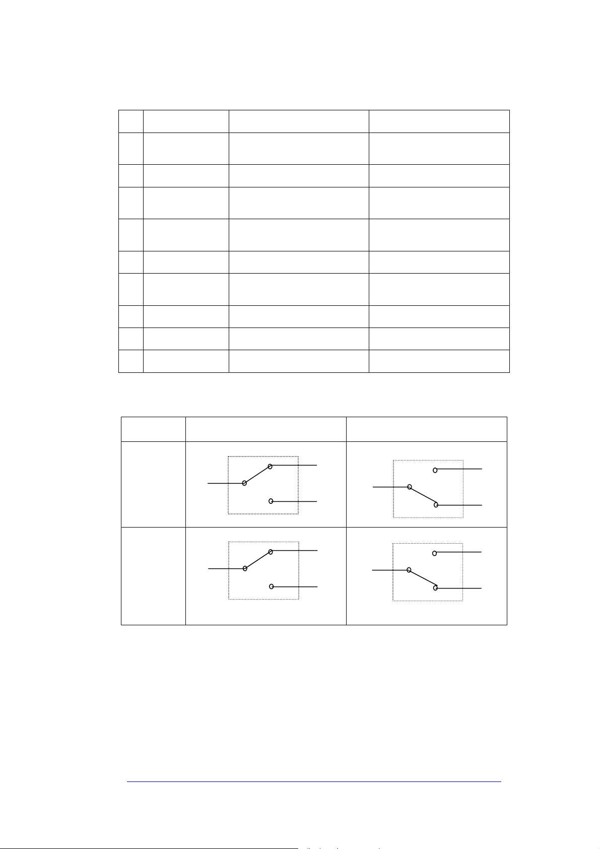
Master/Local Sub-rack Alarm status (SUB-D Male)
PIN Name Meaning Description
1 not connected
2 DL Summary Alarm Common contact
3 not connected
4 UL Summary Alarm Common contact
5 not connected
6 DL Summary Alarm
7 DL Summary Alarm
8 UL Summary Alarm
9 UL Summary Alarm
To choose in conjunction with PIN 2,
Normally Closed
To choose in conjunction with PIN 2,
Normally Open
To choose in conjunction with PIN 4,
Normally Closed
To choose in conjunction with PIN 4,
Normally Open
Tab. 6 Master sub-rack alarm connector pinout
2 - 6 = Open circuit if Local Sub rack
Downlink is in alarm
2 – 7 = Short circuit if Local Sub rack
Downlink is in alarm
4 - 8 = Open circuit if Local Sub rack
Uplink is in alarm
4 – 9 = Short circuit if Local Sub rack
Uplink is in alarm
normal condition (no alarm) Alarm Condition
Down Link
2
6
2
7
Up Link
8
4
4
9
If a slave sub-rack is connected via TSU012 Control Unit or TFLB Interconnect Link
Unit, alarms from slave/remote sub rack are also reported through the TPR back
plane at the auxiliary DB9 female connector, providing alarm relay logic similar to
the master ( see Tab. 7)
NOTE: TPR subrack provides connections for more detailed alarms, at the right
most slots (see TSU012 control unit product specification)
6
7
8
9
BRITECELL System Manual MN010-04 June 2003 Page 38 of 78
The company has a policy of continuous product development and improvement and we therefore
reserve the right to vary any information quoted without prior notice.
Slave/Remote Sub-rack Alarm status (SUB-D Female)
PIN Name Meaning Description
1 UL Summary Alarm
2 UL Summary Alarm Common contact
3 DL Summary Alarm
4 DL Summary Alarm
5 DL Summary Alarm Common contact
6 UL Summary Alarm
7 not connected
8 not connected
9 not connected
To choose in conjunction with PIN 2,
Normally Open
To choose in conjunction with PIN 5,
Normally Closed
To choose in conjunction with PIN 5,
Normally Open
To choose in conjunction with PIN 2,
Normally Closed
Tab. 7 Slave sub-rack alarm connector pinout
2 – 1 =Short circuit if Remote Sub
rack Uplink is in alarm
5 - 3 =Open circuit if Remote Sub
rack Downlink is in alarm
5 – 4 =Short circuit if Remote Sub
rack Downlink is in alarm
2 - 6 =Open circuit if Remote Sub
rack Uplink is in alarm
Normal Condition (no alarm) Alarm Condition
Down Link
Up Link
5
3
5
4
3
4
6
2
2
1
6
1
BRITECELL System Manual MN010-04 June 2003 Page 39 of 78
The company has a policy of continuous product development and improvement and we therefore
reserve the right to vary any information quoted without prior notice.
27. Installation and cabling
27.1. Location
The TPR sub-rack should be placed as near as possible the BTS or the RF repeater.
The sub-rack location should be easy to reach by the users in order to allow alarm
monitoring.
WARNING! do not close the air circulation subrack grids (top and bottom) with
9
panels or obstacles.
If the subrack mounting location does not have a good air circulation, leave at
9
least one unit (1HE) free between subracks.
27.2. Power supply
The connection to the mains has to be carried out following all the necessary
precautions, including the following:
• in accordance with diligence rules (ex. CEI rules, IEC rules, etc.);
• in accordance with the rules for the safety against direct or indirect contacts;
• in accordance with the rules for the safety against over current (short circuit,
overloading);
• in accordance with the rules for the safety against the over tension;
• the connection is to be carried out by properly trained technicians.
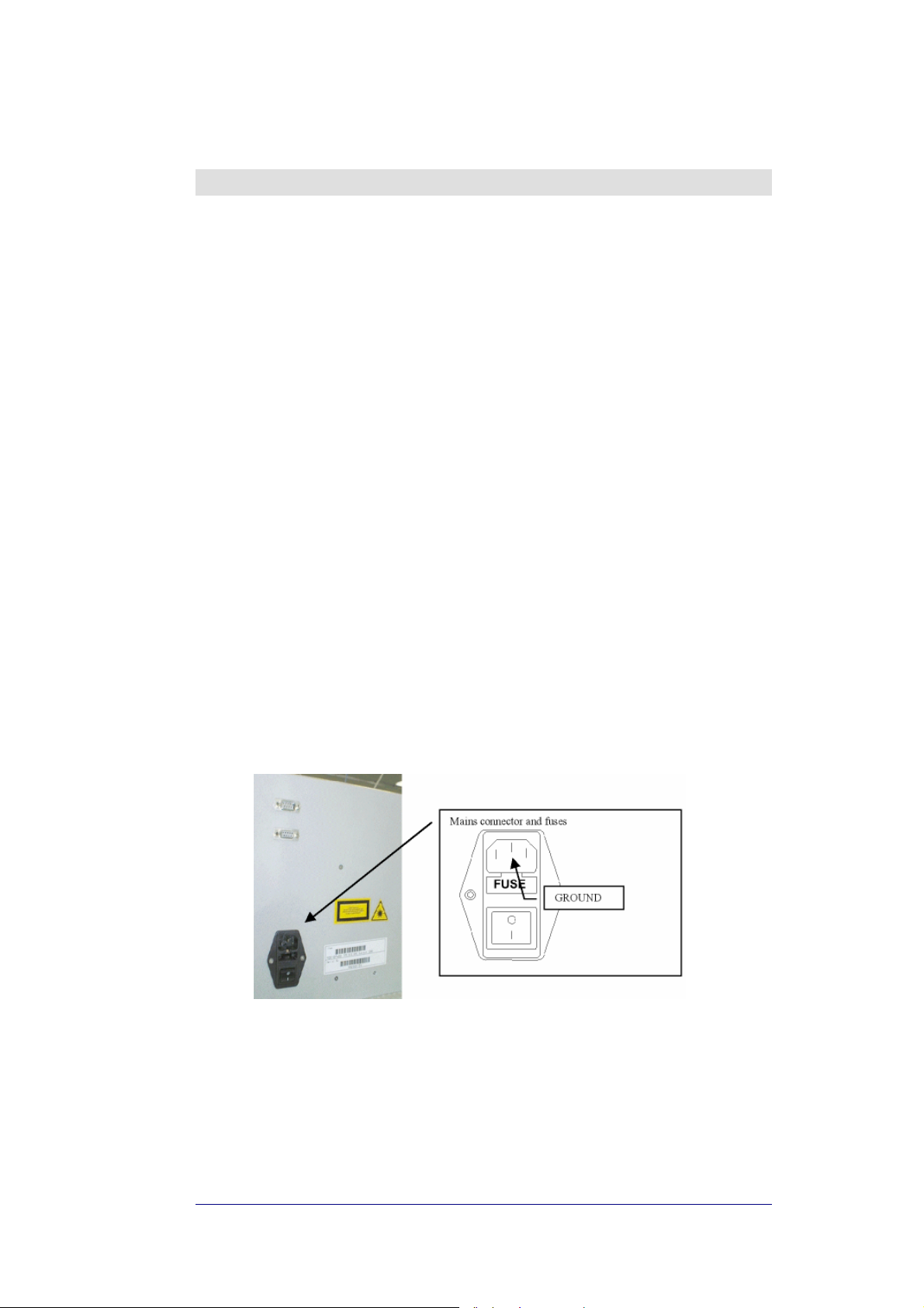
27.2.1. Universal mains
Universal main (85-264VAC, 50/60Hz) apply to TPR912 model only. Mains
connector is placed on the back panel (see Fig. 26 mains connector)
Fig. 26 mains connector
The TPR912 model has an internal AC/DC converter. With 220VAC power supply
the efficiency is 75%. Each TFA has a power consumption of 12W, therefore a fully
equipped configuration (6 TFLs) requires (12W x 6) / 0.75 = 96W.
This formula is helpful in verifying the overall power consumption.
BRITECELL System Manual MN010-04 June 2003 Page 40 of 78
The company has a policy of continuous product development and improvement and we therefore
reserve the right to vary any information quoted without prior notice.
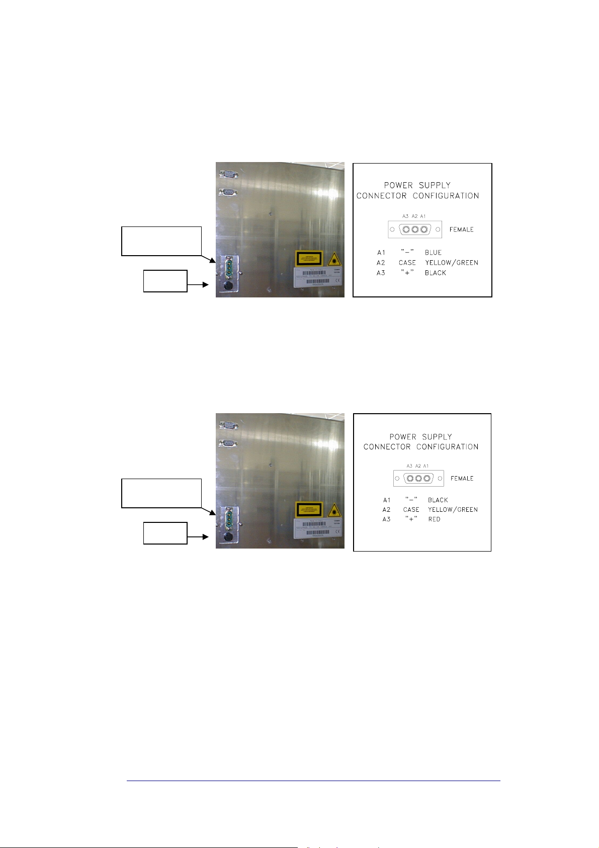
27.2.2. DC negative supply
Direct current ( –72 to –36 VDC) apply to TPR922 model only. Power connector is
placed on the back panel (see
Fig. 27 VDC Connector (TPR922 only))
MALE POWER
CONNECTOR
FUSE
Fig. 27 VDC Connector (TPR922 only)
TPR922 model has an internal DC/DC converter: power consumption is the same
as above.
Direct current (16 to 24 VDC) to be applied to TPR932 model only. Power
connector is placed on the back panel (see Fig. 28 VDC Connector (TPR932 only))
MALE POWER
CONNECTOR
FUSE
Fig. 28 VDC Connector (TPR932 only)
TPR932 model has an internal DC/DC converter: power consumption is the same
as above.
BRITECELL System Manual MN010-04 June 2003 Page 41 of 78
The company has a policy of continuous product development and improvement and we therefore
reserve the right to vary any information quoted without prior notice.
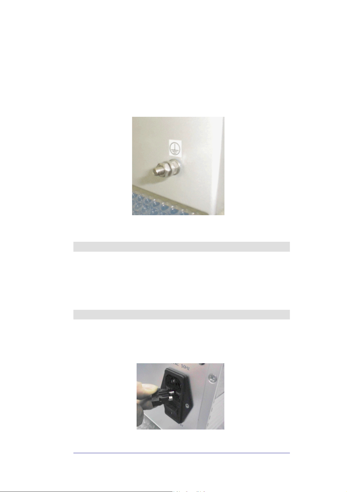
27.2.3. Grounding
Ground terminals are part of power supply connectors, as showed in previous
figures (Fig. 26 mains connector, Fig. 27 VDC Connector (TPR922 only), Fig. 28
VDC Connector (TPR932 only)).
An external grounding terminal, with screw, is available at the back panel (see Fig.
29 ground)
Fig. 29 ground
28. Start up
WARNING: Verify voltage levels before connecting and powering on the
9
subrack
Please refer to system start-up section for further details.
29. Troubleshooting
The way a fuse is changed depends on the subrack version (refer to the
datasheet). One or two fuses are present on the back of the rack, which needs to
be replaced when they fail
BRITECELL System Manual MN010-04 June 2003 Page 42 of 78
The company has a policy of continuous product development and improvement and we therefore
reserve the right to vary any information quoted without prior notice.
Fig. 30 fuse

TFL-BSI RF attenuator
30. Introduction
This section describes the TFL-BSI (Base Station Interface). The TFL-BSI is part of
the Britecell system and allows the operator to optimise the signal level the BTS or
repeater and the Britecell system. It includes two independent variable attenuators
(30 dB, one dB step) for uplink and downlink RF path.
A single attenuator version is available, for downlink only or uplink only operations.
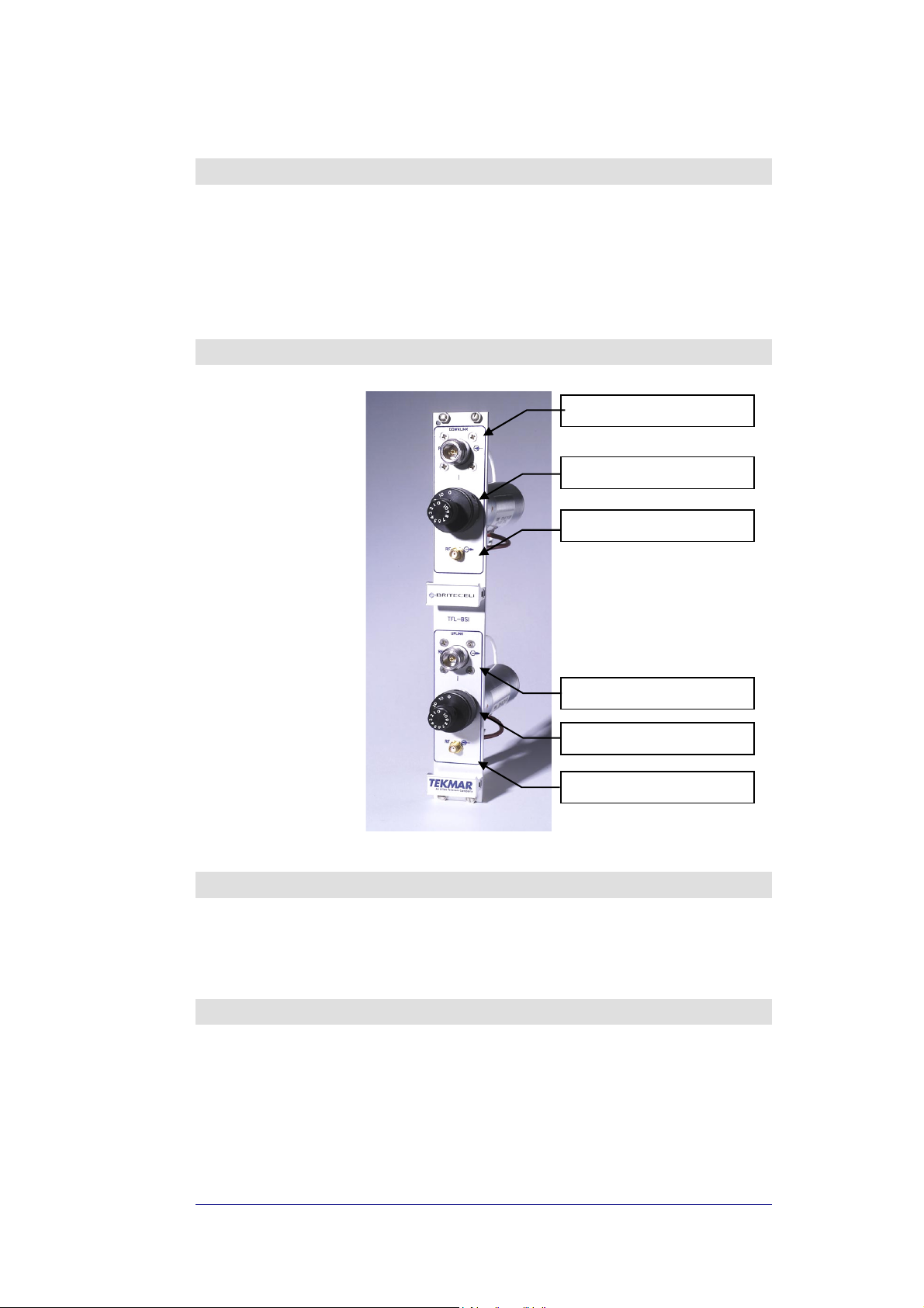
31. Part description
Fig. 31 - TFLBSI
Downlink RF input (from BTS)
Downlink attenuation settings
Downlink RF output (to TFL)
Uplink RF output (to BTS)
Uplink attenuation settings
Uplink RF input (from TFL)
32. Warnings
9
Maximum RF composite input power must not exceed 30 dBm.
9
SMA connectors must be screwed with a proper dynamometric key.
33. Functional description
33.1. Down link operation
If the RF signal coming from the BTS or repeater in downlink path has a power
level, which is not adequate to the TFL’s characteristics, an attenuator is required.
BRITECELL System Manual MN010-04 June 2003 Page 44 of 78
The company has a policy of continuous product development and improvement and we therefore
reserve the right to vary any information quoted without prior notice.

33.2. Uplink operation
The RF signal coming from the mobile through the TFA and TFL in the uplink
direction may not be an optimal level. When this is the case, the uplink attenuator
is used to prevent the BTS from being over driven.
34. Installation and cabling
34.1. TPR housing
The TFL-BSI is a modular plug-in card designed to be put in a 6 HE sub-rack (TPR
family).
The TFL-BSI interfaces with the BTS transmitter and receiver through N-female
connectors and with Britecell with SMA-female connectors.
The connection with the BTS may be direct, if the BTS’s transmitter and receiver
are separated, or through a circulator or a common path RF combiner (please refer
also to THYB section).
When the system is air interfaced through a repeater a common path RF combiner
is required in order to separate the uplink and downlink path.
The connection between TFL-BSI and Local Units may be direct or through a
combiner stage (please refer to TLC section) depending on the system’s
configuration.
35. Calculation of attenuation setting
35.1. Downlink
Calculation of Downlink TFL-BSI setting is made in order to supply Britecell Local
Unit with correct DL input power.
)(]dB[
PILILPA
−−−=
where:
P
IL
IL
P
@POI_Input
Dir.Coupler
Comb.Net
DL_BC_Max
[dBm/c]= RF power level per carrier at POI input:
[dB]= Directional coupler insertion loss (if present);
. [dB]= Combining Network insertion loss;
[dBm/c]= Max input power per carrier at Local Unit input.
35.2. Uplink
Calculation of Uplink TFL-BSI setting is made to meet BTS uplink blocking
requirements.
where:
P
LU_UL@Blocking
[dBm]= Local Unit output power when Remote Unit is at blocking
level (3 dB C/N degradation);
P
BTS@Blocking
[dBm]= BTS receiver blocking level;
SM = Safe margin (typically 3 dB).
)]([]dB[
BlockingBTSNetbCCpouplerDirBlockingULLUblkULBSI
@.om.@___
MaxBCDLNetbCCpouplerDirInputPOIDLBSI
__.om._@_
+−+−=
SMPILILPA
BRITECELL System Manual MN010-04 June 2003 Page 45 of 78
The company has a policy of continuous product development and improvement and we therefore
reserve the right to vary any information quoted without prior notice.

TLC RF combiner - splitter
36. Introduction
This section describes the TLC splitter/combiner. The TLC is part of Britecell
system and provides a family of 2-way and 3-way RF power combiners in order to
allow several local interface modules to be connected to common UL and DL RF
paths, for interfacing to the BTS.
All units have internal pads (one per path) to achieve predefined insertion loss.
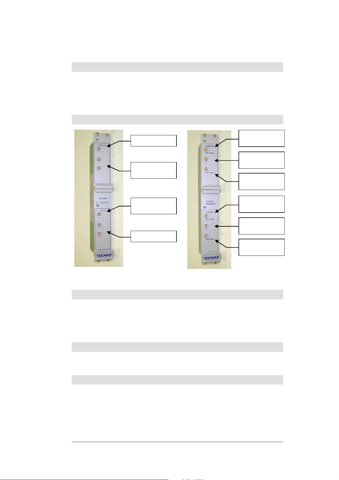
37. Part description
Downlink RF input
Downlink RF
splitted outputs
Uplink RF
combined output
Uplink RF inputs
Fig. 32 TLC2502 Fig. 33 TLC2501
Downlink RF
High Band input
Downlink RF
combined output
Downlink RF
Low Band input
Uplink RF
High Band output
Uplink RF
combined input
Uplink RF
Low Band output
38. Functional description
TLC2502/3 is a two/three way splitter for downlink path and combiner for uplink
path. For insertion loss values refer to datasheets.
TLC2501 is a crossband coupler, designed to combine or split hi-band signal and
low band signal in dual band systems. Insertion loss in this case is minimal (see
datasheets).
39. Warnings
9
Maximum RF composite input power must not exceed 24 dBm.
9
SMA connectors must be screwed with a proper dynamometric key.
40. Installation and cabling
40.1. TPR housing
The TLC is a modular plug-in card, suited to be contained in a 6 HE Sub rack (TPR
family).
The 2-way TLC module interfaces with the BTS transmitter and receiver through
TFL-BSI and with TFL Local Units directly or through 3-way splitter/combiner.
BRITECELL System Manual MN010-04 June 2003 Page 47 of 78
The company has a policy of continuous product development and improvement and we therefore
reserve the right to vary any information quoted without prior notice.

THYB common path RF
combiner

41. Introduction
This section describes the THYB common path RF combiner family. THYB is part of
Britecell system and it allows combining of downlink and uplink path into a single
one, while maintaining required isolation and stability.
This component has been designed for Britecell system configuration requiring
single RF connector carrying both DL and UL signals when system is interfaced
through a diplexed BTS.
42. Part description
Fig. 34 THYB
DL/UL RF combined
input/output
Uplink RF
input
Downlink RF
output
43. Functional description
THYB is a bi-directional hybrid RF combiner/splitter. It can be chosen in single or
dual band version. It’s provided with uplink pass-band filters to improve UL
isolation performances.
THYB typical application is in conjunction with diplexed BTS where DL and UL
paths are provided in single RF connector.
For insertion loss value, refer to datasheets.
44. Warnings
9
Maximum RF composite input power must not exceed 30 dBm.
9
SMA connectors must be screwed with a proper dynamometric key.
45. Installation and cabling
THYB is a modular plug-in card, suited to be contained in a 6 HE Sub rack (TPR
family). THYB interfaces with BTS transceiver through ‘C’ connector (type SMAfemale). THYB interfaces with Britecell downlink and uplink paths through ‘DL’ and
‘UL’ connectors respectively (type SMA-female).
BRITECELL System Manual MN010-04 June 2003 Page 49 of 78
The company has a policy of continuous product development and improvement and we therefore
reserve the right to vary any information quoted without prior notice.

TFB booster

46. Introduction
The TFBxx is an optional part of the Britecell system and it’s intended to enhance
transmit power of Britecell remote transceivers TFA in order to maintain an output
power of 10 dBm per carrier when operating with up to 8 carriers.
Typical TFB configuration is together with TFA remote unit and TPA passive
antennae.
TFB is housed in the same metallic case as TFA and contains one amplifier for each
direction (uplink and downlink).
47. Part description
power on led (green)
alarm led (red)
power supply
alarm relay contact
(normally closed)
RF port to TFA
Fig. 35 TFB RF booster
warm side
RF port to
coverage antenna
48. Warnings
CAUTION! Do not connect the booster to TFA without first switching power
9
supply off.
49. Functional description
49.1. Block diagram
High Band Booster
TFA remote unit
Fig. 36 block diagram
BRITECELL System Manual MN010-04 June 2003 Page 51 of 78
The company has a policy of continuous product development and improvement and we therefore
reserve the right to vary any information quoted without prior notice.
ALC
AMP
AMP
TPA antenna

(
(input)
49.2. Description
TFB booster is a bi-directional RF amplifier designed to:
• improve the coverage area of the antennae connected to the remote unit
while maintaining same amount of distributed RF carriers;
or
• improve number of distributed RF carriers while preserving the same
coverage area.
Only single band version is available.
To enhance both RF ports of TFA remote unit, two TFB boosters are needed.
Downlink operation:
in downlink path, the booster performs an overall gain of 14
dB. ALC (automatic level control) circuit provides automatic limitation of excess
output power.
Uplink operations:
in uplink path, the booster has an overall gain of 4 dB, which
decreases the uplink noise figure (increasing system sensitivity).
50. Alarms
TFB provides a logic alarm related to excess current draw. The alarm output must
be connected to TFA external alarm input , as shown in Fig. 37
TFB relay contact
output)
Fig. 37
TFA relay contacts
51. Installation and cabling
WARNING: for a proper connection of TFB to the Britecell system through the
9
TFA. Please refer to the system coverage design for additional information.
51.1. Location
TFB booster unit shall be installed close to TFA remote unit and radiating
antennas, as to minimise coaxial cable length.
The unit is intended to be installed on walls, flat or orthogonal surface.
For a proper unit cooling take care of the warm unit side as indicated in Fig. 35
Installation must provide the correct positioning, and cables must be run so that
accidental damage is prevented.
BRITECELL System Manual MN010-04 June 2003 Page 52 of 78
The company has a policy of continuous product development and improvement and we therefore
reserve the right to vary any information quoted without prior notice.

51.2. Power supply and grounding
51.2.1. Universal mains (85-264VAC, 50/60Hz)
Mains
Fig. 38 -Mains connector
51.2.2. DC negative supply –72 to –36 VDC.
DC connector and part number:
Fig. 39 - VDC connector
Ground
Mains
51.3. RF combined ports
Antenna port must be directly connected to radiating antennas through RF
jumpers.
TFA port must be connected to combined port of TFA remote unit.
52. Start up
A preliminary verification of TFB correct operation is:
• power-up the TFB
• verify the following led status
LED Colour Status
Alarm Red OFF if internal operations ok
Power On Green ON
For a full functionality test please refer to the system start-up section
BRITECELL System Manual MN010-04 June 2003 Page 53 of 78
The company has a policy of continuous product development and improvement and we therefore
reserve the right to vary any information quoted without prior notice.

53. Troubleshooting
In case of alarm LED is active, check first if the air circulation around the unit is
acceptable and that environmental conditions (operating temperature, supply
range) are among specified operating limits.
If problems persists please refer to service or technical support.
BRITECELL System Manual MN010-04 June 2003 Page 54 of 78
The company has a policy of continuous product development and improvement and we therefore
reserve the right to vary any information quoted without prior notice.

TPA antenna

54. Introduction
This section describes the TPA antenna family. The TPA is part of Britecell system
and provides the field shaped coverage.
TPA realises the physical radiating points, for radio transmission/reception, towards
mobile stations. Each TPA is connected to the relevant Remote Unit TFA by means
of coaxial jumper. TPA family ranges from single band stand-alone to dual band
Fig. 40 TPAx10 single band antenna Fig. 41 TPAx20 dual band antenna
Fig. 42 TPAx30 dual band antenna
BRITECELL System Manual MN010-04 June 2003 Page 56 of 78
The company has a policy of continuous product development and improvement and we therefore
reserve the right to vary any information quoted without prior notice.

55. Functional description
The TPA extends cellular coverage in such indoor environments that can't be
economically and easily reached by radio mobile network signals.
RF signals going through walls, metallic structures and any other obstacle inside
buildings are attenuated up to 1000 times (30 dB), thus creating problems for the
users of mobile phones.
TPA together with TFA solves this problem by providing a suitable amplification,
which compensates the fading effect due to various artificial obstacles placed
between mobile phones and Radio mobile Network.
The TPA can be high-gain directional or low-gain semi-directional, see product
family datasheet for detailed radiation patterns
The appliance to the following instructions grants the best functioning, the
maximum safety and the lowest inference with other electrical devices.
Any misuse and any violation of the device compromise its functioning and exclude
any warranty.
TFA
Remote Unit
Fig. 43 block diagram
Coverage area
TPA antenna
BRITECELL System Manual MN010-04 June 2003 Page 57 of 78
The company has a policy of continuous product development and improvement and we therefore
reserve the right to vary any information quoted without prior notice.

56. Installation and cabling
56.1. Location
Britecell transmits low-power radio signals in a given area. It is important to
respect the simple installation instructions as follows, in order to achieve a good
communication quality and to avoid malfunctions, which could bring to a selfinhibition of the device.
The TPA passive antenna’s placing should be chosen in order to grant the
maximum indoor radio coverage. The largest field is located perpendicular to the
TPA. Antennas have to be mounted at a minimum height of 2.5m from the ground.
They should not be placed near trees, plants, metal grids or other obstacles, which
could disturb their functioning and lead to a worsening of the device's
performance.
COVERAGE
ANTENNA
Fig. 44 antenna position
Minimum Coverage
Direction
CORRECT
Fig. 45 radiation pattern
2.50 m
WRONG
Maximum Coverage
Direction
BRITECELL System Manual MN010-04 June 2003 Page 58 of 78
The company has a policy of continuous product development and improvement and we therefore
reserve the right to vary any information quoted without prior notice.

56.2. Location examples
Fig. 46 Rectangular room Fig. 47 Corridor
Fig. 48 Garage
56.3. Wall mount
Fig. 49 Front view fig. 50 Side view
BRITECELL System Manual MN010-04 June 2003 Page 59 of 78
The company has a policy of continuous product development and improvement and we therefore
reserve the right to vary any information quoted without prior notice.

56.4. Connectivity
There is either an N-female connector or a RG223 pigtail attached to the TPA
antenna to realise connection to the TFA.
WARNING: use only low loss 50Ω RF cable to connect TPA antenna to TFA.
9
WARNING: do not connect the antenna without switching off the power supply
9
to the TFA.
57. Troubleshooting & maintenance
The device has no particular maintenance requirements. It is advisable to check
periodically the cable connecting the external antenna, in order to avoid any
erosion or cut which could reduce its lifetime.
BRITECELL System Manual MN010-04 June 2003 Page 60 of 78
The company has a policy of continuous product development and improvement and we therefore
reserve the right to vary any information quoted without prior notice.

SYSTEM INSTALLATION

58. Installation and cabling
Britecell is designed to be simple and fast to install and commission. It requires a
minimum number of tools and equipment. However, it is necessary to observe
local regulations when planning and implementing an RF system and safety
conventions must be strictly adhered to at all times. One unique hazard with
Britecell is the presence of optical equipment; a thorough working knowledge of
optics, and the safety procedures in their use, is required by the installation,
commissioning and maintenance staff.
58.1. Local unit and subrack location
TFL Local Interface Units should be placed as near as possible to the BTS or the RF
repeater and should be easily accessible as they provide visual alarm information
for the system maintenance.
TPR 19" subrack needs proper air circulation. Take care that the operating
9
temperature range is met.
58.2. Remote unit and antennas location
The most efficient locations for the TFA Remote Transceivers will minimise the
number of antennas required, whilst maintaining the coverage level goal.
Please refer to the system design for the proper antenna location.
The position of the remote unit should be vertical to improve the thermal
9
dissipation.
There should be easy access to the optical and RF cables.
9
58.3. Fibre-Optic Cables
Britecell employs single-mode optic-fibre (SMOF) with the standard characteristic
dimensions of 9µm (core)/125µm (cladding).
The amount of protection needed by the fibre varies from one application to
another. A variety of cable designs are available to meet the requirements of
different installations. Here are some examples:
• Loose tube construction
tube so that it can adjust itself when the cable is distorted; microbending
is almost completely eliminated by this technique. Loose tube cables are
preferred for long distance links and for almost all outdoor applications.
• Tight buffer construction
cushioning material (secondary coating up to an external diameter of
900µm) to improve crush resistance and vibration isolation, minimising
microbending. Tight buffer cables are usually adopted for indoor
applications because they offer small cross-section dimensions and small
bend radius.
: The fibre lies loosely inside a surrounding plastic
: the buffered fibre is completely enclosed in a
BRITECELL System Manual MN010-04 June 2003 Page 62 of 78
The company has a policy of continuous product development and improvement and we therefore
reserve the right to vary any information quoted without prior notice.

For in-building applications the most common fibre cables are tight buffered cables
with 2 fibres; examples are:
Duplex zip-cord: two simplex units in a zip cord configuration.
External
Dimension
(mm)
2.5 x 5.3 30 11 30 (minor axis)
Maximum
Tension
(kg)
Weight
(kg/km)
Minimum Bend
Radius (mm)
Duplex breakout cable: two individually coloured simplex units over sheathed in
a “figure 0” configuration.
External
Dimension
(mm)
3.6 x 6 30 24 35 (minor axis)
Duplex light duty wiring cable: two individually coloured tight buffered fibres
surrounded by yarn annulus with a polymer over sheath.
External
Dimension
(mm)
5 81 19 40
The main differences between these cables concern the maximum tension that
they can bear; this is an important characteristic to consider as, during laying,
installers often have to pull and to drag cables. For this reason the duplex lightduty wiring cable is preferred, which is light and allows a tight band radius.
Maximum
Tension
(kg)
Maximum
Tension
(kg)
Weight
(kg/km)
Weight
(kg/km)
Minimum Bend
Radius (mm)
Minimum Bend
Radius (mm)
58.3.1. Connecting TFL and TFA with optical cables
A couple of fibre optics connects every Remote Unit with a TFL. It is very
important to well organise the layout of cables in order to avoid mistakes in the
connection (correspondence between a certain remote unit and a TFL).
Furthermore, a well-organised layout, allows good maintenance and
troubleshooting.
Every fibre must be labelled in order to understand which is the correspondence
between TFL port and Remote Unit.
During the connection of the pigtails to the TFL, some rules must be followed.
The pigtail cannot be squeezed or on traction and the minimum bend radius
9
suggested is 4 cm.
Don’t touch the fibre optic head of the optical connector
9
If necessary, clean the connector head by means of alcohol and proper paper
9
Use dry air spray to clean the TFL optical connector. Firstly spray to another
9
direction and then inside the connector as often some water can be on the first
spray.
Do not use other methods behind these to clean the optical connectors.
9
BRITECELL System Manual MN010-04 June 2003 Page 63 of 78
The company has a policy of continuous product development and improvement and we therefore
reserve the right to vary any information quoted without prior notice.

58.3.2. Optical Cable Laying
Fiberoptic cables can be pre-terminated with appropriate fibre connectors,
however, this often times causes problems if there is not enough space to pull
through the connector, or if the cable lengths become very large. A qualified
installer can make a recommendation on this matter. It is always recommended
that extra fibre length be provisioned. The common (and recommended) method
is to run the fibre cables without connectors attached and splice short preconnectorised tails onto the fibre. This avoids damaging connectors in the cablerunning process and ensures that adequate length is available at each end for
correct routing and strain relief.
Note that angled connectors cannot be fitted in the field due to the accurate
polishing process required; there is no significant loss in performance due to a
fusion splice.
Inside the optical cable trunk, other kinds of cable cannot be installed.
The optical cable must not be stressed as this can cause a high insertion loss, and
it could therefore break. For this reason it is important not to squeeze the cable,
for example tightening the fixing stripes too much.
It’s a good rule of thumb to avoid bending the optical cable within a radius of less
than 10 cm. Consequently, the cable trunk installation must be done respecting
that norm.
The following are pictures of actual cabling, one correct, one incorrect.
WRONG BETTER
fig. 51 - system cabling
BRITECELL System Manual MN010-04 June 2003 Page 64 of 78
The company has a policy of continuous product development and improvement and we therefore
reserve the right to vary any information quoted without prior notice.

58.4. Power Supply
A Britecell system may be locally (at each remote unit) or distributed powered.
There are advantages with both methods. It may be faster and cheaper to use
local power, however it is easier to back-up a system when the power originates at
a single point. A power supply may be distributed in a composite cable (copper
and fiber), or two separately parallel cables may be run. Note that the cable
containing the copper conductors must carry the appropriate plenum rating and
must be of sufficient conductor area to ensure adequate voltage at the furthest
Remote Unit under full load. Refer to TFA datasheet for power consumption
specifications.
If Local Units subrack is to be co-located with a BTS it is often desirable to power
the entire system from the battery-backed low voltage supply available. The Local
Unit card is fitted with a universal AC power supply module but can be ordered
with -48VDC modules instead. The overall power consumption of a full equipped
subrack will not exceed 110W.
A general rule for subrack power consumption is:
(Local Unit consumption [W]) x (cards number) / 0.75 = overall consumption [W]
59. SYSTEM START-UP
In order to avoid damaging the equipment, the following criteria must be used
to start up the system:
1. Verify all the power supply connections.
2. Verify all the RF connections.
3. Verify all the optical connections.
4. Set all the adjustable attenuators on the TFL-BSI at the maximum value of
attenuation.
5. Switch on the local units sub-racks.
6. Check for alarm status and in case of alarm refer to troubleshooting
paragraph.
7. Connect the spectrum analyser at the input of one TFL and measure the level
of the carriers for every operator.
8. Set the adjustable attenuators in order to have the right level of the carriers at
the input of the TFL according to the technical specifications.
BRITECELL System Manual MN010-04 June 2003 Page 65 of 78
The company has a policy of continuous product development and improvement and we therefore
reserve the right to vary any information quoted without prior notice.

60. MAINTENANCE
60.1. Plug-in cards removal
Always switch off subracks power supply before removing or inserting any
9
active plug-in card.
60.2. Optical equipment
It is a good rule when working with the fibre optic components, to always have
available the appropriate screw covers for closure of the optic connectors that are
not connected. The intrinsic fragility of an optic connection must be highlighted. A
minimum layer of dust causes a notable increase of the insertion loss, therefore.
Always close the optic connectors that are not connected, with the appropriate
9
screw covers.
Always use compressed gas to remove any deposits in the receptacles before
9
closing them.
Use the appropriate cloths to clean the connectors.
9
Do not allow the male connector to come into contact with skin or oily
9
surfaces.
Should it be necessary to clean the optic connector, use pure alcohol only.
9
BRITECELL System Manual MN010-04 June 2003 Page 66 of 78
The company has a policy of continuous product development and improvement and we therefore
reserve the right to vary any information quoted without prior notice.

OTHER INFORMATION

61. TERMINOLOGY
The following acronyms are commonly used throughout the document:
AC Alternating Current
AM Amplitude Modulation
AMPS Advanced Mobile Phone System (US 800 MHz standard)
BTS Base Transmission Station (cellular system element)
DC Direct Current
DCS Digital Communication System (European 1800 MHz standard)
DL Down-link (radio path from BTS to subscriber)
EMC Electro-Magnetic Compatibility
ETACS Extended Total Access Communications System
(European 800MHz standard)
GSM Global System for Mobile
IMD Intermodulation Distortion
LNA Low-Noise Amplifier
LV Low Voltage
SMOF Single Mode Optical Fibre
PCB Printed Circuit Board
PCS Personal Communications System (US 1900 MHz standard)
RF Radio Frequency
TFA Britecell remote transceiver (also called Fiber Remote Unit)
TFL Britecell local interface unit (also called Fiber Donor Unit)
UL Up-link (radio path from subscriber to BTS)
UMTS Universal Mobile Telecommunication System
62. WARRANTY CONDITIONS
Customer service is granted all over the world during and after the warranty
period.
Allen Telecom warrants to the terms and conditions hereto set forth, all products
manufactured by it to be free under normal use and service from defects in
materials and workmanship for a period of one (1) year from the date of shipment
to the first consumer (the “Warranty Period”).
The warranty applies only if:
a) the warranty period is not expired;
b) the defect is imputable to the product.
Our obligation under this Warranty is limited to prompt repair or replacement of
the product, without charge, when the product is returned to the factory.
The warranty shall not apply to any product which has been repaired or altered in
any manner or if the defect, malfunction or failure of the product was caused by
damage by lightning, flood or other acts of nature or by power surges, or from
unreasonable use, or from improper installation or application, or to any product
which has not been maintained or used in accordance with the operating
specifications set forth in this manual.
Allen Telecom evaluates if the product can be repaired or if it is necessary to
replace the unit.
BRITECELL System Manual MN010-04 June 2003 Page 68 of 78
The company has a policy of continuous product development and improvement and we therefore
reserve the right to vary any information quoted without prior notice.

In case the product is out of warranty, the customer will be informed about the
cost for repairing or replacing the unit. The service will be provided only after
receiving Customer’s authorisation.
Before returning the goods, the customer should give prior notice to Allen Telecom
through normal return authorisation procedure.
Allen Telecom aims to offer an excellent service. To do that we ask our customer
to enclose to the returned product an accompanying letter, including the following
information
Company name
Address
Contact person
Invoice number
Delivery note
N°. of pieces
Model*
Serial Number*
Lot*
Year*
Description of the
Failure/defect
* refer to the serial label
N.B.: each product must be packaged with care before shipment.
Allen Telecom will issue a check report, which is included in the packing together
with the product being returned. The customer will be informed about any
corrective actions suggested by quality assurance.
BRITECELL System Manual MN010-04 June 2003 Page 69 of 78
The company has a policy of continuous product development and improvement and we therefore
reserve the right to vary any information quoted without prior notice.

63. DECLARATION OF CONFORMITY
Allen Telecom
Declares
That the device related to this usage and maintenance handbook comply with the
CE mark requirements, according to the Low Tension Rules 73/23/CEE and
Electro-magnetic compatibility Rules 89/392/CEE
Allen Telecom will carefully retain the technical file related to the device design,
together with this usage and maintenance handbook, for a minimum time span of
10 years.
Signature: Managing Director of Tekmar Sistemi S.r.l.
64. TECHNICAL SUPPORT
For further information on the product, not described in this publication, please
contact our helpdesk:
Tekmar Sistemi s.r.l – technical support & system engineering
Via De Crescenzi 40 - 48018- Faenza - ITALY
tel ++39.0546.697111
fax ++39.0546.682768
An online service using our Internet site is available.
web: http//:www.tekmar.it/helpdesk
e-mail: info@tekmar.it
BRITECELL System Manual MN010-04 June 2003 Page 70 of 78
The company has a policy of continuous product development and improvement and we therefore
reserve the right to vary any information quoted without prior notice.

APPENDIX

65. APPENDIX A - Britecell system design basics
65.1. Indoor propagation
Radio signals from wireless mobile telephone systems are located in the high UHF
spectrum, between 800MHz and 2,2GHz, according to the common standards such
as ETACS, AMPS, GSM, DCS, PCS, UMTS, etc.. At such high frequencies
electromagnetic waves are subjected to phenomena like diffraction and reflection;
these effects become dominant in cellular systems where propagation rarely occurs
in free space.
In a cellular system a single radiation point is normally provided for each cell or
sector, located at the BTS site. This may not have line of sight to every user in the
coverage area.
The simultaneous occurrence of diffraction and multiple reflections (multipaths) in
the indoor environment makes this the most critical, as far as signal propagation
and coverage is concerned. The presence of natural or artificial openings and
obstructions (such as walls) leads to a mean loss term, which is normally higher
than the free space loss.
The point is easily reached in indoor environments where the radio link loss
exceeds the maximum loss, determined by the transmitter power and receiver
sensitivity, for acceptable communication quality. This can happen in a few spots
of a room, affecting uniform coverage, or in entire sections of the building.
A common issue is the need to provide sufficient signal level in all parts of a
structure to dominate the signal from a local external cell, ensuring that calls
originating within the building are set-up on the internal system. This can add a
considerable challenge to the in-building coverage design as very high signal levels
may be required close to external openings, such as doors and windows.
When supplying cellular coverage to indoor environments, in order to reach full
network performances, receive levels at both the BTS and mobile handset must be
kept uniformly high by keeping link loss as low as possible. This can be obtained
using Britecell.
When supplying coverage to indoor composite areas, the radiation points should
be planned to be in line of sight with the mobile so that the radio link loss can be
kept consistently low.
The location of the BTS is no longer determined by the required radiation point;
more practical BTS locations are thus feasible and the radiation point locations can
be optimised to suit the coverage area.
Deploying a Britecell system fulfils these criteria. By using fibre optic guided
propagation very low link losses can be achieved, allowing signals to be carried
long distances in the building without appreciable degradation. Specific areas can
be targeted to fit traffic distribution, regardless of obstructions or location; cell
planning is simplified with minimum or no changes in network parameters setting.
In addition, the use of Britecell can avoid the introduction of further BTS's, where
coverage is required but there are no requirements for more traffic channels. This
can achieve considerable savings in the cellular system rollout.
BRITECELL System Manual MN010-04 June 2003 Page 72 of 78
The company has a policy of continuous product development and improvement and we therefore
reserve the right to vary any information quoted without prior notice.

65.2. Fibre-optic transmission
Britecell uses an analogue modulation scheme for the transmission of the
composite RF signal through the fibre optic link; the optical carrier is intensity
modulated.
Distortion is critical in cellular systems due to the multiple carriers present and the
regular channel spacing ensures that the products usually occur on the frequency
of another channel.
To minimise these problems Britecell uses high performance single mode lasers as
RF to optical transducers, the characteristics of which are dominant in the link
performance. Single mode optical fibre (SMOF) is employed due to its very low
loss, enabling signals to be carried for long distances when matched with sensitive
optical receivers.
With Britecell optical links in excess of 1.5 km can be achieved without appreciable
degradation of signal characteristics. Care must be taken to keep back reflection of
the optical carrier below -36 dBC to avoid additional link noise and signal
distortion.
We can detect two contributions to back reflection in optical links:
Microscopic variations in the refractive index in the fibre cause scattering of the
light; this depends on fibre length and can be kept within allowable limits by
limiting the length.
Concentrated reflections, due to refractive index discontinuity’s in the fibre are the
dominant source of returned light. These occur mainly at optical connectors so, to
reduce the severity, Britecell uses angled connectors, which direct reflected light
out of the fibre core. Only a negligible portion of light from the interface is
reflected back towards the source; return losses of greater than 60 dB can be
achieved with angled optical connectors.
In case that the system operates on a digital standard, a fundamental parameter
for the transparency is propagation delay through fibre, especially when the indoor
coverage extends an existing outdoor coverage of a BTS because of the need for
an outdoor-indoor overlap area. In this case differential delay between the direct
and repeated paths must be minimised. For example, the upper limit for GSM
systems is 8µs.
The velocity factor of silica glass optical fibre is 0.65, giving a propagation delay in
the fibre of 5ms/km; the Britecell equipment has a negligible contribution.
Optical fibre needs only a little care to be taken in system implementation and
maintenance to avoid possible malfunction. It offers many major advantages in inbuilding coverage design, apart from the ability to carry signals long distances.
Significant additional benefits are:
• High bandwidth capacity
• Electromagnetic Compatibility (EMC) of fibre optics is inherent in all
environments; fibre is insensitive to electromagnetic fields, lightning or
radiation and produces no interference to other equipment.
• SMOF cables for indoor applications can be very thin, easy to install and to
hide; thus they permit a low visual impact on the environment and a
minimum effort in their laying.
• Support structures can be minimal and no plenum-rated jacketing is
required for use inside structures (unless copper conductors are
incorporated).
Refer to the following sections for more information on the design and installation
fibre cabling in Britecell systems
BRITECELL System Manual MN010-04 June 2003 Page 73 of 78
The company has a policy of continuous product development and improvement and we therefore
reserve the right to vary any information quoted without prior notice.

65.3. Coverage method
The greatest benefit of Britecell fibre optic distribution system is the possibility to
place non obtrusive antennas where the coverage is needed, i.e. near the mobile
users.
The coverage targets, in terms of signal levels, are meant to be achieved by
placing radiating points inside the building.
Antenna locations are selected in order to:
• minimise path loss to mobiles in the public areas of the building,
• minimise number of remote antenna sites.
A careful planning of antenna position allows to achieve a low attenuation radio
link, since it minimises the effect of obstacles and it brings the radiating points
close to the mobile stations, often achieving a quasi line of sight propagation.
This also greatly reduces the fading effects. As a result, good quality radio links
can be achieved with low down link and up link transmit powers.
The low power Distributed Antenna System (DAS) provides uniform and well
confined coverage inside buildings.
BRITECELL System Manual MN010-04 June 2003 Page 74 of 78
The company has a policy of continuous product development and improvement and we therefore
reserve the right to vary any information quoted without prior notice.

b
66. APPENDIX B - Britecell input power level setting
66.1. Down link power levels
In order to achieve spurious products below the limits set forth in various
governmental specifications (eg. -36 dBm for GSM900, –30 dBm for GSM1800) the
input power at the TFL downlink input port should be set according to the
following table. FCC specifications (-13 dBm- AMPS, PCS) are somewhat more
lenient and are also dependent on spectral mask requirements.
TFL DL RF
input
TFL UL RF
output
NOTES:
DL power levels for Britecell 900 MHz and Britecell 1800 MHz
TFLxxxx4H-x
TFAxxxx
b
a
NUMBER OF
CARRIERS
(N)
Max power per carrier at
TFL DL RF input (a)
P
/carrier [dBm]
IN TFL
Max power per carrier at
TFA RF output (b)
P
/carrier [dBm]
OUT TFA
2 3,0 10,0
3 0,7 7,7
4 -0,3 6,7
5 -1,2 5,8
6 -1,8 5,2
7 -2,3 4,7
8 -2,7 4,3
9 -3,1 3,9
10 -3,4 3,6
11 -3,7 3,3
12 -4,0 3,0
14 -4,5 2,5
16 -4,9 2,1
18 -5,2 1,8
20 -5,6 1,4
22 -5,8 1,2
26 -6,4 0,6
30 -7,1 -0,1
34 -7,6 -0,6
40 -8,3 -1,3
BRITECELL System Manual MN010-04 June 2003 Page 75 of 78
The company has a policy of continuous product development and improvement and we therefore
reserve the right to vary any information quoted without prior notice.

66.2. Down link power levels: remote unit + booster
TFL DL RF
input
TFL UL RF
output
NUMBER OF
CARRIERS
(N)
NOTES:
DL power levels for Britecell 900 MHz + TFB915
DL power levels for Britecell 1800 MHz + TFB1815
The DL levels at Booster output assume that the cable connecting TFA and booster
has 1 dB loss.
TFLxxxx4H-x
TFAxxxx
b
c
TFBxxxx
b
a
Max power per
carrier at TFL DL RF
input (a)
P
/carrier
IN TFL
[dBm]
Max power per
carrier at TFA RF
output (b)
P
OUT TFA
/carrier
[dBm]
Max power per
carrier at TFB RF
output (c)
P
OUT TFB
/carrier
[dBm]
1 0,0 7,0 20,0
2 -4,0 3,0 16,0
3 -6,3 0,7 13,7
4 -7,3 -0,3 12,7
5 -8,2 -1,2 11,8
6 -8,8 -1,8 11,2
7 -9,3 -2,3 10,7
8 -9,7 -2,7 10,3
9 -10,1 -3,1 9,9
10 -10,4 -3,4 9,6
11 -10,7 -3,7 9,3
12 -11,0 -4,0 9,0
14 -11,5 -4,5 8,5
16 -11,9 -4,9 8,1
18 -12,2 -5,2 7,8
20 -12,6 -5,6 7,4
22 -12,8 -5,8 7,2
26 -13,3 -6,3 6,7
30 -13,8 -6,8 6,2
34 -14,1 -7,1 5,9
40 -14,6 -7,6 5,4
BRITECELL System Manual MN010-04 June 2003 Page 76 of 78
The company has a policy of continuous product development and improvement and we therefore
reserve the right to vary any information quoted without prior notice.

f
67. APPENDIX C - Classifying hazardous areas
Hazardous Area
A hazardous area is defined as: "An area in which a flammable substance in the
form of gas or vapour or dust, when mixed with air, is present in such proportions
that it can explode when in contact with an ignition source.
Area Classification
Hazardous areas are classified with respect to the potential danger or an explosion,
and the areas are divided into zones:
CONDITIONS CE Code EC
Continuously Hazardous Division 1
Periodically Hazardous Division 1
Occasionally Hazardous Division 2
Gases & vapour classification
Gases are grouped together basing on the amount of energy required to ignite the
most explosive mixture of the gases with air. Equipment is classified into groups
according to the gases and vapours for which it is suitable and must be selected
with a grouping, which covers the gases and vapours which, will be present where
it is to be installed:
Group Representative Gas Ignition Energy
I
IIA
IIB
IIC
GAS CE CODE IEC
Acetylene Class I, Group A Group IIC
Hydrogen, Butadiene, Ethylene Oxide, Propylene Oxide, or Acrolein Class I, Group B Group IIC
Ethylene, Cyclopropane, Ethyl Ether, or Ethylene Class I, Group C Group IIB
Propane, Acetone, Alcohol, Ammonia, Benzine, Benzol, Butane,
Gasoline, Hexane, Laquer Solvent vapours, Naptha, Natural Gas
Coal Mines
Combustible Dusts Class II
Ignitable Fibres or Flying Class III
To ensure the suitability of electrical equipment for use in hazardous areas, the
equipment is certified and uses various techniques known as Methods of
Protection. As not all Methods of Protection are suitable for all hazardous areas,
care must be taken to select equipment, which is suitable for use in the Zone in
which it is installed.
Zone 0 Zone 1 Zone 2
Ex ia - Intrinsic safety
Ex s - Special protection i
specifically certified for Zone 0
* may be suitable for Zone 1
BRITECELL System Manual MN010-04 June 2003 Page 77 of 78
The company has a policy of continuous product development and improvement and we therefore
reserve the right to vary any information quoted without prior notice.
Zone 0 - An area in which an explosive gas/air mixture is
continuously present or is present for long periods.
Zone 1 - An area in which an explosive gas/air mixture is
likely to occur under normal operating conditions.
Zone 2 - An area in which an explosive gas/air mixture is
unlikely to occur, but if it occurs, it will be of short duration.
Methane
Propane
Ethylene
Hydrogen
Method suitable for Zone 0
Ex ib - Intrinsic Safety
Ex d - Flameproof enclosure
Ex e - Increased safety
Ex m - Encapsulation
Ex s - Special protection
320 Microjoules
300 Microjoules
160 Microjoules
40 Microjoules
Class I, Group D Group IIA
Gaseous Mines Group 1
Method suitable for Zone 0 or l
Ex N - Type of protection N
Ex o - Oil immersion*
Ex q - Powder filling*
Ex p - Pressurised or purging

68. APPENDIX D - Health and safety warnings
Antenna installation must conform within the following guidelines to meet FCC RF
exposure limits, otherwise an environmental evaluation is required if:
Broadband PCS (subpart E):
Non building mounted antennas: Height above ground level to lowest point of
Building-mounted antennas: Total power all channels>2000W ERP (3280W EIRP)
Narrowband PCS (subpart D):
Non-building-mounted antennas: Height above ground level to lowest point of
Building-mounted antennas: Total power of all channels > 1000 W ERP (1640 W
Cellular Radiotelephone Service
(Part 22, subpart H):
Non-building-mounted antennas: Height above ground level to lowest point of
Building-mounted antennas: Total power of all channels > 1000 W ERP (1640 W
Paging and Radiotelephone Service
(Part 22, subpart E):
Non-building-mounted antennas: Height above ground level to lowest point of
Building-mounted antennas: Total power of all channels > 1000 W ERP (1640 W
Private Land Mobile Radio \
Specialized Mobile Radio (Part 90):
Non-building-mounted antennas: Height above ground level to lowest point of
Building-mounted antennas: Total power of all channels > 1000 W ERP (1640 W
antenna< 10m Radio (Part 24) and total power of all
channels > 2000 W ERP (3280 W EIRP)
antenna < 10m Radio (Part 24) and total power of
all channels > 1000 W ERP (1640 W EIRP).
EIRP).
antenna < 10m Radio (Part 22) and total power of
all channels > 1000 W ERP (1640 W EIRP).
EIRP).
antenna < 10m Radio (Part 22) and total power of
all channels > 1000 W ERP (1640 W EIRP).
EIRP).
antenna < 10m Radio (Part 90) and total power of
all channels > 1000 W ERP (1640 W EIRP).
EIRP).
BRITECELL System Manual MN010-04 June 2003 Page 78 of 78
The company has a policy of continuous product development and improvement and we therefore
reserve the right to vary any information quoted without prior notice.
 Loading...