

User’s Manual
for
Node C Prototype
Network Elements
with Interface Unit
ID No: 161692 PRELIMINARY Page 1

© Copyright 2004 Mikom GmbH
All rights reserved.
User’s Manual for Node C Network Elements
All information contained in this manual has been revised thoroughly. Yet Mikom An
Andrew Company accepts no liability for any omissions or faults.
Mikom An Andrew Company reserves the right to change all hard- and software
characteristics without notice.
Names of products mentioned herein are used for identification purposes only and
may be trademarks and/or registered trademarks of their respective companies.
No parts of this publication may be reproduced, stored in a retrieval system,
transmitted in any form or by any means, electronical, mechanical photocopying,
recording or otherwise, without prior written permission of the publisher.
Mikom GmbH An Andrew Company, 16-February-2004
Page 2
M0121A1A_uc.doc

TABLE OF CONTENTS
1 GENERAL 7
1.1 ABBREVIATIONS 7
1.2 HEALTH AND SAFETY WARNINGS 8
1.3 PREAMBLE 9
1.4 INTERNATIONAL CONTACT ADDRESSES 10
2 INTRODUCTION 11
2.1 PURPOSE 11
2.2 THE NODE C NETWORK ELEMENT 11
2.3 QUICK START CHECKLIST 12
3 INSTALLATION 13
3.1 MECHANICAL INSTALLATION 13
3.1.1 General 13
3.1.2 Wall Mounting Procedure 14
3.1.3 Connection Option 16
3.1.4 Pole Mounting Procedures 17
3.2 ELECTRICAL INSTALLATION 20
3.2.1 General 20
3.2.2 Grounding 21
3.2.3 Power Connection 22
3.2.4 Connection of the Antenna Cables 23
3.2.5 Connection of Cable Bridge 23
3.2.6 Connections for Optional Equipment 24
4 COMMISSIONING 25
4.1 GENERAL 25
4.2 SOFTWARE SETUP 26
4.2.1 Remote Control 26
4.2.2 Connection Devices 26
4.2.3 Connection Procedures 26
4.2.3.1 Setup Overview 26
4.2.3.2 Installing the USB driver 27
4.2.3.3 Direct connection for Windows XP 28
4.2.3.4 Modem connection for Windows XP 38
4.2.3.5 Direct connection for Windows 2000 48
4.2.3.6 Accessing the web page 60
4.2.4 Main Menus of the Web Page 61
4.2.4.1 Setup Wizard 61
4.2.4.2 Connectivity and Upload 63
4.2.4.3 Technician Setup 64
4.2.4.4 Alarm Management 65
4.3 TROUBLESHOOTING 66
ID No: 161692 PRELIMINARY Page 3

User’s Manual for Node C Network Elements
5 FUNCTIONAL DESCRIPTION 69
5.1 GENERAL 69
5.2 FEATURES OF THE NODE C 72
5.2.1 Filters 72
5.2.2 Digital ICE (Digital Interference Cancellation Equipment) 72
5.2.3 VSWR (Voltage Standing Wave Ratio) 73
5.2.4 RSSI (Receive Signal Strength Indication) 73
5.2.5 Alarmforwarding 73
5.2.6 External Alarms 74
5.2.7 Summary Alarm 75
5.3 COMPONENTS OF THE NODE C AND INTERFACE UNIT 76
5.3.1 Duplexer 76
5.3.2 RF and DC Distribution Unit 78
5.3.3 Digital Channel Module (DCM) 79
5.3.4 Uplink Final Amplifier 80
5.3.5 Downlink Final Amplifier 80
5.3.6 Distribution & Alarm Board 82
5.3.7 Power Supply 83
5.4 OPTIONAL EQUIPMENT 83
5.4.1 Modem with Battery Backup 83
5.4.1.1 Initstrings 84
5.4.1.2 Wireless Modem 84
5.4.1.3 Battery Backup 85
5.4.2 PSU Redundancy 86
5.4.3 High Rejection Filter 86
6 MAINTENANCE 87
6.1 GENERAL 87
6.2 REPLACEMENT OF COMPONENTS 87
6.2.1 Power Supply 88
6.2.2 Battery Backup 89
6.2.3 Fan Unit 89
6.2.4 Modem 90
7 APPENDIX 91
7.1 ILLUSTRATIONS 91
7.1.1 Cabinet Drawings 91
7.1.2 Layout 93
7.2 SPECIFICATIONS 96
7.2.1 Electrical Specifications 96
7.2.2 Mechanical Specifications 98
7.2.3 Specifications for Optional Equipment 98
7.3 PARTSLISTS 99
7.3.1 Interface Unit 99
7.3.2 Node C 100
8 INDEX 101
Page 4
M0121A1A_uc.doc

FIGURES AND TABLES
figure 3-1 Positions of drilling holes........................................................................................ 14
figure 3-2 Wall mounting procedure.......................................................................................15
figure 3-3 Connection option..................................................................................................16
figure 3-4 Cabinet combining kit.............................................................................................16
figure 3-5 Pole mounted systems...........................................................................................17
figure 3-6 Back-to-back pole mounting...................................................................................18
figure 3-7 Pole mounting two systems ...................................................................................19
figure 3-8 Grounding bolts......................................................................................................21
figure 3-9 Grounding a system...............................................................................................21
figure 3-10 Power supply plug................................................................................................22
figure 3-11 Mains connector...................................................................................................22
figure 3-12 Front view of antenna connections ......................................................................23
figure 3-13 Connector panel of the Node C............................................................................24
figure 3-14 Connector panel of the Interface Unit ..................................................................24
figure 4-1 Front and top cover screws....................................................................................25
figure 4-2 Position of mains power switch..............................................................................25
figure 4-3 USB and null modem cable connection.................................................................27
figure 4-4 Home page of web interface..................................................................................60
figure 4-5 Setup Wizard..........................................................................................................61
figure 4-6 Connectivity and Upload menu..............................................................................63
figure 4-7 Technician Setup menu .........................................................................................64
figure 4-8 Alarm Management menu......................................................................................65
figure 5-1 DC block diagram of a Node C ..............................................................................69
figure 5-2 Configuration of a Node C network element..........................................................70
figure 5-3 RF path of a Node C, exemplary............................................................................71
figure 5-4 Configuration of external alarm clamps..................................................................74
figure 5-5 Summary alarm relay.............................................................................................75
figure 5-6 Layout of a Node C 1943 and Interface Unit..........................................................76
figure 5-7 Duplexer, DL IN......................................................................................................77
figure 5-8 Duplexer, UL IN, with integrated diversity filter......................................................77
figure 5-9 RF / DC distribution unit.........................................................................................78
figure 5-10 DCM (UL or DL part)............................................................................................79
figure 5-11 Uplink final amplifier.............................................................................................80
figure 5-12 Node C x37 DL final amplifier ..............................................................................80
figure 5-13 Node C x43 DL final amplifier, new type..............................................................81
figure 5-14 Node C x43 DL final amplifier, former version .....................................................81
figure 5-15 Distribution & alarm board....................................................................................82
figure 5-16 Power supply........................................................................................................83
figure 5-17 Battery backup module, exemplary......................................................................85
figure 6-1 Power supply screws .............................................................................................88
figure 6-2 Location of battery backup.....................................................................................89
figure 6-3 Fan unit screws......................................................................................................89
figure 6-4 Fan connector cable...............................................................................................90
figure 6-5 Mounting plate of modem.......................................................................................90
figure 7-1 Cabinet of a Node C...............................................................................................91
figure 7-2 Cabinet of a Node C Interface Unit........................................................................92
figure 7-3 Layout of the Node C 1937, exemplary..................................................................93
figure 7-4 Layout of the Node C 1943, exemplary..................................................................94
figure 7-5 Layout of the Interface Unit, exemplary .................................................................95
ID No: 161692 PRELIMINARY Page 5

User’s Manual for Node C Network Elements
table 1-1 List of international contact addresses....................................................................10
table 3-1 Mounting distance...................................................................................................14
table 3-2 Required length of thread-bolts and cable bridge ...................................................17
table 3-3 Components of pole mounting kits..........................................................................18
table 4-1 Assisted antenna tuning..........................................................................................62
table 5-1 Connections of RF / DC distribution unit.................................................................78
table 5-2 Standard initstring for modem................................................................................. 84
table 6-1 Specified torques for various screw types...............................................................88
Page 6
M0121A1A_uc.doc

1 General
1 GENERAL
1.1 ABBREVIATIONS
A/D Analogue to Digital Converter
ALC Automatic Level Control
ARFCN Absolute Radio Frequency Channel Number
BITE Built In Test Equipment
BTS Base Transceiver Station
CDMA Code Division Multiple Access
CF Center Frequency
CFO Center Frequency Offset
D/A Digital to Analogue Converter
D-ICE Digital Interference Cancellation
DCM Digital Channel Module
DL Downlink
DSP Digital Signal Processor
EMIF External Me mory Interface
ESB Embedded System Block
ESD Electrostatic Discharge
ETSI European Telecommunication Standards Institute
FPGA Field Programmable Gate Array
FRU Field Replaceable Unit
2
I
C Bus Inter Integrated Circuit Bus (Philips)
ICE Interference Cancellation Equipment
ID No Identification Number
IF Intermediate Frequency
LE Logic Elements
LMT Local Maintenance Terminal
LVPECL Low Voltage Positive Emitter Coupled Logic
MSPS Mega Samples Per Second
NCO Numerically Controlled Oscillator
OMC Operation and Maintenance Centre
PCMCIA Personal Computer Modem Communication International Association
PLL Phase Lock Loop
PSTN Public Switched Telephone Network
RF Radio Frequency
RLP Radio Link Protocol
RSCP Received Signal Code Power
RSSI Receive Signal Strength Indication
RTC Real Time Clock
RX Receiver
SCL Serial Clock
SDA Serial Data
SMS Short Message Service
TS Transmitter
UL Uplink
UMTS Universal Mobile Telecommunication System
UPS Uninterruptible Power Supply
VSWR Voltage Standing Wave Ratio
WCDMA Wide-band Code Division Multiple Access
ID No: 161692 PRELIMINARY Page 7

1.2 HEALTH AND SAFETY WARNINGS
1. Only suitably qualified personnel is allowed to work on this unit and only after
becoming familiar with all safety notices, installation, operation and maintenance
procedures contained in this manual.
2. Read and obey all the warning labels attached to the unit. Make sure that the
warning labels are kept in a legible condition and replace any missing or
damaged labels.
3. Obey all general and regional installation and safety regulations relating to work
on high voltage installations, as well as regulations covering correct use of tools
and personal protective equipment.
4. Keep operating instructions within easy reach and make them available to all
users.
5. It is the responsibility of the network provider to implement prevention measures
to avoid health hazards which may be associated to radiation from the antenna(s)
connected to the unit.
6. Make sure, access is restricted to qualified personnel.
7. Use this equipment only for the purpose specified by the manufacturer. Do not
carry out any modifications or fit any spare parts which are not sold or
recommended by the manufacturer. This could cause fires, electric shock or other
injuries.
8. Due to power dissipation, the network element may reach a very high
temperature.
9. Before opening the unit, disconnect mains.
10. ESD precautions must be observed! Before commencing maintenance work, use
the available grounding system to connect ESD protection measures.
11. This unit complies with European standard EN60950.
12. Make sure the network element settings are according to the intended use (see
also product information of manufacturer) and regulatory requirements are met.
13. Although the network element is internally protected against overvoltage, it is
strongly recommended to earth the antenna cables close to the network
element’s antenna connectors for protection against atmospheric discharge.
User’s Manual for Node C Network Elements
Page 8
M0121A1A_uc.doc

1 General
1.3 PREAMBLE
Mikom An Andrew Company is a leading manufacturer of coverage equipment for
mobile radio networks, specializing in low cost, high performance, RF and optical
repeaters. Our optical distributed networks and RF repeater systems provide
coverage for every application: outdoor use, indoor installations, tunnels, subways
and many more.
Mikom has engineering and manufacturing facilities in Germany, Italy and the USA.
In addition, it maintains many field engineering offices throughout the world.
Mikom GmbH operates a quality management system which complies with the
requirements of ISO 9001. All equipment is manufactured using only highly reliable
materials. In order to ensure constant first-rate quality of the products, a
comprehensive quality assurance has been conducted at all fabrication stages. Every
component leaves the factory only after a thorough final acceptance test,
accompanied by a test certificate guaranteeing optimal function.
The declaration of conformity for the product is available on request via the local
offices or from Mikom directly.
Any intervention must be carried out by authorized persons only. If technical
assistance for the product is required, please contact the local office or Mikom
directly at one of the following addresses:
Mikom GmbH An Andrew Company
Industriering 10
86675 Buchdorf
Germany
Phone: +49 (0) 9099 69 0
Fax: +49 (0) 9099 69 930
email: WIsupport.germany@andrew.com
for The Americas:
Mikom US An Andrew Company
Phone: +1 (919) 771-2570
email: WIsupport.us@andrew.com
When set-up is performed according to this manual, the system will operate without
complications for a significant length of time.
ID No: 161692 PRELIMINARY Page 9

User’s Manual for Node C Network Elements
1.4 INTERNATIONAL CONTACT ADDRESSES
in Australia
6 Stuart Street
Padstow NSW 2211
Australia
Phone: +61 (2) 9774-4200
Fax: +61 (2) 9774-4500
email:
WIsupport.australia@andrew.com
in the UK
Guildgate House
Pelican Lane
Newbury
RG14 1NX, Berkshire, U.K.
Phone: +44 (1635) 569-695
Fax: +44 (1635) 569-463
email:
WIsupport.uk@andrew.com
in France
Z.I. des Ebisoires
78370 Plaisir
France
Phone: +33 (1)30-79-15-36
Fax: +33 (1) 30-55-55-37
email:
WIsupport.france@andrew.com
in China
Ground Floor, Unit F, Tower 2
The Astoria 198 Argle Street,
Mau Tau Wai, Kowloon
Hongkong
Phone: +852 2778 3187
Fax: +852 2778 3187
email:
WIsupport.china@andrew.com
in the USA
108 Rand Park Drive
Garner
NC 27529
USA
Phone: +1 (919) 771-2570
Fax: + 1 (919) 771-
email:
WIsupport.us@andrew.com
in Canada
1815 Ironstone Manor, # 12
Pickering, Ontario L1W 3W9
Canada
Phone: +1 (905) 839-3474
Fax: +1 (905) 839-4663
email:
WIsupport.canada@andrew.com
in Switzerland
Tiergartenweg 1
4710 Balsthal
Switzerland
Phone: +41 (6238) 61260
Fax: +41 (6238) 61261
email:
WIsupport.switzerland@andrew.com
in Czech Republic
U Morusi 888
530 06 Pardubice-Svitkov
Czech. Republic
Phone: +42 (0406) 301280
Fax: +42 (0406) 301298
email:
WIsupport.czechrep@andrew.com
table 1-1 List of international contact addresses
in Italy
Via De Crescenzi 40
48018 Faenza
Italy
Phone: +39 0546 697111
Fax: +39 0546 682768
email:
WIsupport.italia@andrew.com
in Austria
Weglgasse 10
2320 Schwechat
Austria
Phone: +43 (1) 706 – 3999
Fax: +43 (1) 706 – 39999
email:
WIsupport.austria@andrew.com
Page 10
M0121A1A_uc.doc

2 Introduction
2 INTRODUCTION
2.1 PURPOSE
Wireless communication systems provide a two-way information transfer (voice and
data) between a base station and multiple mobiles within a given area.
Environmental variables such as physical structures both man-made (buildings) and
natural (mountains) attenuate signals in the transmission path, which reduce the
transport signal’s strength. This attenuation leads to a reduction in quality and data
rate and eventually prohibits the system’s use entirely. A Node C is specifically
designed to extend coverage, enhance quality, and increase air-interface capacity.
In the downlink (DL), the Node C picks up signals coming from the base station,
filters them, amplifies them, and retransmits them to the mobile. In the uplink (UL), it
picks up signals from the mobile, filters them, amplifies them, and retransmits them to
the base station. The Node C constantly monitors the quality of the signals passing
through it, while simultaneously electronically decreasing isolation requirements.
2.2 THE NODE C NETWORK ELEMENT
The Node C is a primary network element, capable of enhancing up to three adjacent
CDMA carriers in a CDMA system. Its primary function is to increase the signal
strength between multiple mobiles and a base station in areas where basic voice or
high-speed data transmission is not available. It may be used for basic coverage,
signal reinforcement, and cell shaping, which can increase a network’s coverage
area, data rate, and capacity.
The Node C is a dedicated CDMA device. However, several enhancers operating at
different frequencies and technologies may share the same hardware (cables and
antennas) via a crossband coupler. Within the CDMA frequency band, multiple
operators may use the same unit via additional modules, thus reducing cost, while
sharing the user interface and antennas.
The Node C may be set-up locally or remotely. A circuit switch or packet data modem
may be connected to an integrated controller. This provides the network
management system with on-demand, alarm generated, or heartbeat monitoring via
the always-connected packet features. The Node C has features and functions that
may be monitored and changed by the operators via a web-based browser remotely
or locally, or via the SNMP based OMC software platform. The graphical interface of
the Node C provides a setup menu including a setup wizard which allows both setup
and monitoring capability without any equipment required apart from a laptop or PC.
The Node C network element is self-diagnosing, self-adaptive, and virtually
maintenance-free.
ID No: 161692 PRELIMINARY Page 11

2.3 QUICK START CHECKLIST
Read the health and safety warnings in chapter 1.2 Health and Safety Warnings.
Setting up the Node C is quick and easy. The following step-by-step procedure
provides a quick overview for a correct setup and optimization.
a. Required Equipment
• Node C
• donor antenna
• coverage antenna(s) or DAS
• coaxial feeder cable
• connectors
• laptop with connection and mains cable
b. Required Information
Make sure to have the following information at hand:
• important on-site conditions (e.g. base station location, mains supply, etc.)
• channels to be enhanced/amplified
• pilot
• pilot power to total power
User’s Manual for Node C Network Elements
c. Procedure
1. Install the donor and coverage antennas.
2. Install the feeder cable from the Node C to the antennas.
3. Install the Node C (see chapter 3 Installation).
4. Install the Interface Unit (see chapter 3 Installation).
5. Connect cables between the Interface Unit and the Node C (see chapter
3.2 Electrical Installation).
6. Connect power and the antenna f eeder cables to the Node C.
7. Open the Interface Unit as described in chapter 4.1 General.
8. Setup the connection computer (see chapter 4.2 Software Setup) and
establish a connection to the Node C (see chapter 4.2.3 Connection
Procedures).
9. Login to the unit and follow the installation wizard option for easy
installation.
a. Optimize the donor antenna performance (see chapter 4.2.4.1
Setup Wizard).
b. Select the channels for enhancement.
c. Enter the desired output power in the downlink.
d. Enter the pilot power to total power ratio of the donor base
station.
e. Enter the relative uplink gain.
f. Setup the modem (if applicable) and enter data in the other user
fields.
10. The Node C setup is complete.
11. Open the “Save Configuration to Laptop” menu for record keeping
purposes.
12. Unplug the computer, close the Interface Unit and tighten all screws.
Page 12
M0121A1A_uc.doc

3 Installation
3 INSTALLATION
3.1 MECHANICAL INSTALLATION
3.1.1 General
Read the health and safety warnings in chapter 1.2 Health and Safety Warnings.
1. Do not install the unit in a way or at a place where the specifications
outlined in the Environmental and Safety Specifications leaflet of the
manufacturer are not met.
2. It is recommended only to use the mounting hardware delivered by the
manufacturer. If different mounting hardware is used, the specifications
for stationary use of the unit must not be exceeded.
) Note: Exceeding the specified load limits may cause the loss of warranty.
3. The unit is considerably heavy. Make sure that a suitable mounting
surface is used. Ensure there is adequate manpower to handle the
weight of the system.
4. Due to power dissipation, the unit may reach a very high temperature.
Ensure sufficient airflow for ventilation. Above and below the units a
minimum distance of 300* mm to ceiling, floor, etc. has to be kept. This
distance must also be observed between two units if they are mounted
one above the other.
* This value does not apply to the distance between Interface Unit and Node C. The
distance required between the two cabinets is specified in table 3-1 Mounting distance.
If any different or additional mounting material is used, ensure that the mounting
remains as safe as the mounting designed by the manufacturer. Ensure that the
static and dynamic strengths are adequate for the environmental conditions of the
site. The mounting itself must not vibrate, swing or move in any way that might cause
damage to the unit.
) Note: Both the Node C and the Interface Unit are delivered with a pre-
mounted front cover. This cover is of vital importance for the
correct forced airflow (of Node C 43) and for passive cooling (of
Node C 37 and Interface Unit). Thus, do not operate the units
without cover.
ID No: 161692 PRELIMINARY Page 13
User’s Manual for Node C Network Elements
3.1.2 Wall Mounting Procedure
• Check the wall mounting kit and the wall to determine their suitability.
• The maximum distance between the Node C and the Interface Unit depends on
the length of the cable bridge (standard length is 500 mm) by which they will be
connected (see table 3-1 Mounting distance). Thus, before marking the mounting
positions, check the length of the cable bridge and make sure to install the units
at a suitable distance.
Mounting style: beside each other* one above the other**
Length of cable bridge: 500 mm 800 mm 2000 mm only 2000 mm possible
Maximum distance 140 mm 400 mm 1600 mm 1000 mm (min.=300 mm)
* Maximum distance is referring to distance between the cabinet sides
** It is recommended to install the Node C above the
between top of lower and bottom of upper unit
Interface Unit; max. distance is the distance
table 3-1 Mounting distance
) Note: The following figures show units that are mounted beside each
other. To install one above the other proceed in the same way, also
observing the specified mounting distance from table 3-1.
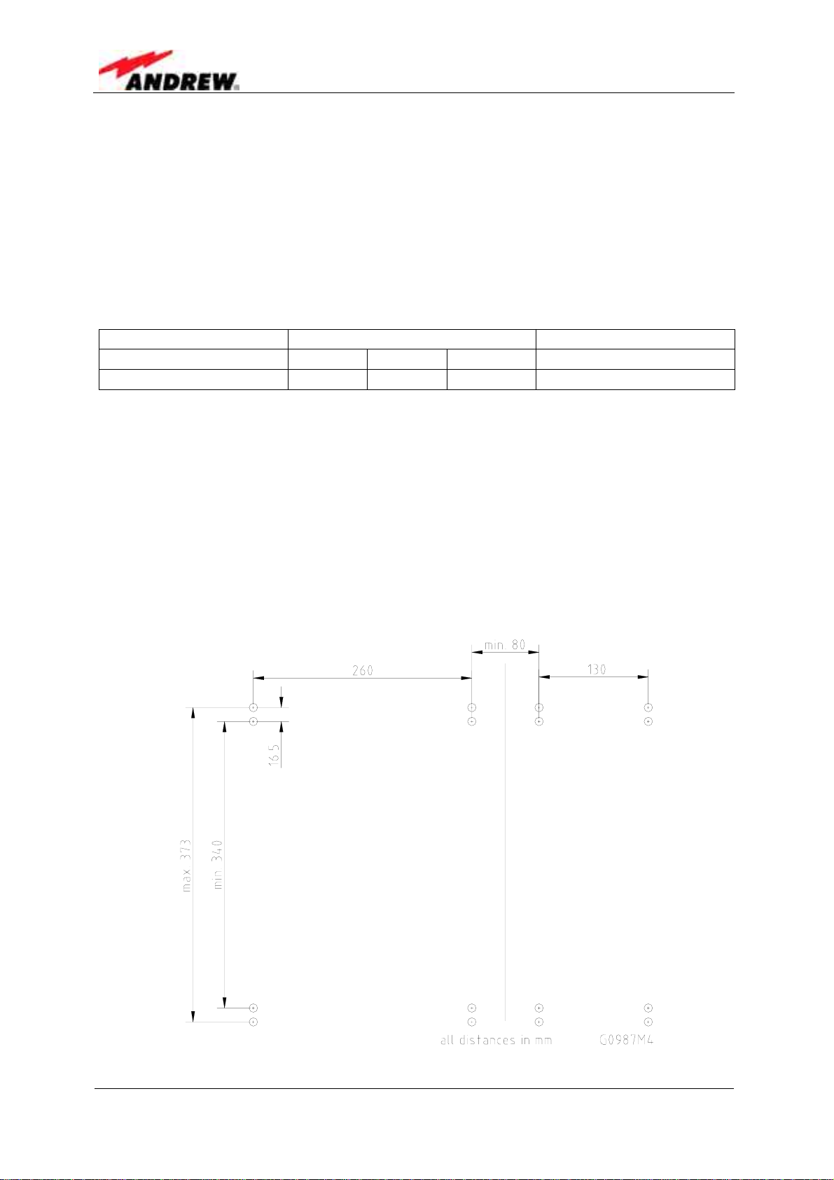
• Mark the position of the eight drilling holes (four per unit) for the Node C and
Interface Unit according to figure 3-1. Please observe that the figure always
shows a pair of drill holes for each position. Only drill one of each pair.
Page 14
figure 3-1 Positions of drilling holes
M0121A1A_uc.doc
3 Installation
) Note: Ensure that there is free access to the electrical connections as well
as to the cabinet. The approved bending radius of the connected
cables must not be exceeded.
• Drill eight holes (four per unit) at the marked positions and insert dowels*.
* The dowels are not part of the delivery (and thus not illustrated in the figure) since the suitable type
depends on the on-site conditions (the material of wall). Therefore, use dowels that are appropriate
for the mounting surface.
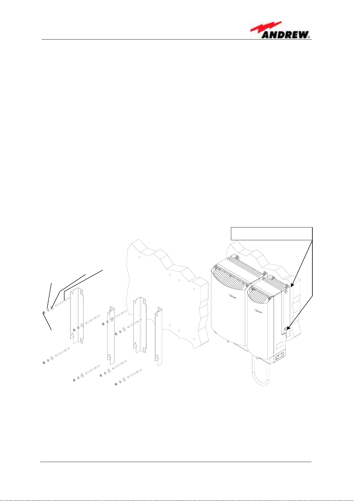
• Use a cap nut or locknut to screw the eight M8 dowel screws into the dowels.
• Use a hex wrench, opening 17 (old standard) or 16 (new standard), to loosen the
M10 hexagon head screws (four per unit) by which the mounting brackets are
fastened to the cabinet sides.
• Mount the mounting brackets to the screws, and fasten them using the M8
washers, locking rings, and hex nuts that are part of the wall mounting kit.
• Hang the cabinets into the brackets and fasten them with the M10 hexagon head
screws*.
M10 hexagon head screws
Plain washer M8 Dowel
Locking ring M8
Hex
nut
screw
figure 3-2 Wall mounting procedure
* If other screws than the ones delivered by the supplier are used for fastening, these must have a
diameter of at least 8 mm and an appropriate length (depending on the dowels). Additionally, make
sure they are adequate for supporting a maximum weight of 50 kg per unit.
For mounting both cabinets as one unit, a cabinet combining kit is available. The
according mounting procedure is explained in the following chapter.
ID No: 161692 PRELIMINARY Page 15
G
User’s Manual for Node C Network Elements
3.1.3 Connection Option
• In order to mount the system using the cabinet combining kit, dismount the
mounting brackets from the cabinets of the units by loosening the hexagon head
screws M10x20 by which the brackets are screwed to the housing (four per unit).
Do not unscrew those screws, only loosen them by approx. three turns and take
off the brackets.
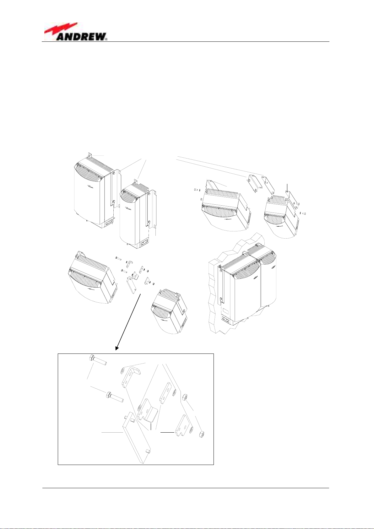
• The two inner brackets are no longer required; exchange the out er brackets and
fasten them to the cabinets (as indicated below).
Brack et 1
1s t s t e p :
Remove and dis car d
2nd st ep:
Exchange Br acket 1
and Br acket 2; t hen
mount as shown:
Br ack et 2
3r d st ep:
Join uni t s and mount
joint syst em to wall
Brack et 2
Br ack et 1
Hexagon head
screws M10x 4
Page 16
figure 3-3 Connection option
Was he r DIN12 5
Bracket sConne ct i ng pl at e
figure 3-4 Cabinet combining kit
M0121A1A_uc.doc
M10 nu t s
G0987M
G0987M G
• Join the two cabinets using
the parts of the cabinet
combining kit as indicated.
• Use the special mounting
plan supplied as part of the
cabinet combining kit for
drilling the according holes
and mount the system to the
wall.

3 Installation
3.1.4 Pole Mounting Procedures
The following figure illustrates the two pole mounting options:
back-to-back (left) and two systems (right).
figure 3-5 Pole mounted systems
• Before starting the mounting procedure, check the pole diameter of the pole to
which the units will be installed; then, cut the thread-bolts (see table 3-3
Components of pole mounting kits, pos. 5) to the required length according to the
following table, which also states the appropriate cable bridge lengths:
Pole-diameter
(mm)
Length of ThreadBolt (mm)
Length of cable
bridge (mm)
(back-to-back)
Length of cable
bridge (mm)
(for 2 systems)
table 3-2 Required length of thread-bolts and cable bridge
100 110 120 130 140 150 160 170 180 190 200
216 226 236 246 256 266 276 286 296 306 317
800 2000
800 2000
ID No: 161692 PRELIMINARY Page 17
Both types of pole mounting kit consist of the following parts (in different quantities):
No Part No Part
1 Pole mounting brace 5 Thread-bolt M8
2 Washer DIN 9021 – 8.4 6 Washer M8 DIN 125
3 Nut M8 DIN 934 7 Hexagon head screw M8
4 Spring ring DIN 127 – A8 8 Fastener
table 3-3 Components of pole mounting kits
The numbers in the above table refer to the numbering of the components in the
following figures. Positions 7 and 8 are only required for mounting two systems.
User’s Manual for Node C Network Elements
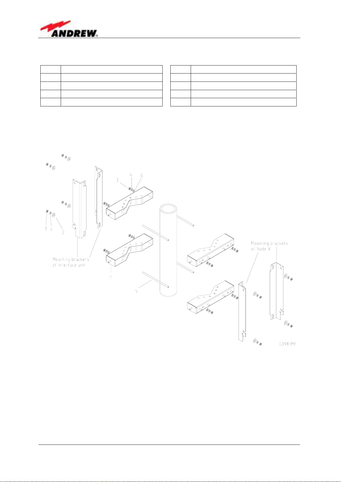
figure 3-6 Back-to-back pole mounting
• Dismount the mounting brackets from the cabinets of the units by loosening the
hexagon head screws M10x20 by which the brackets are screwed to the housing
(four per unit). Do not unscrew those screws, only loosen them by approx. three
turns and take off the brackets.
• Fasten the mounting brackets to the pole using the corresponding mounting kit as
illustrated in figure 3-7 Pole mounting two systems or figure 3-6 Back-to-back pole
mounting, respectively.
Page 18
M0121A1A_uc.doc
3 Installation
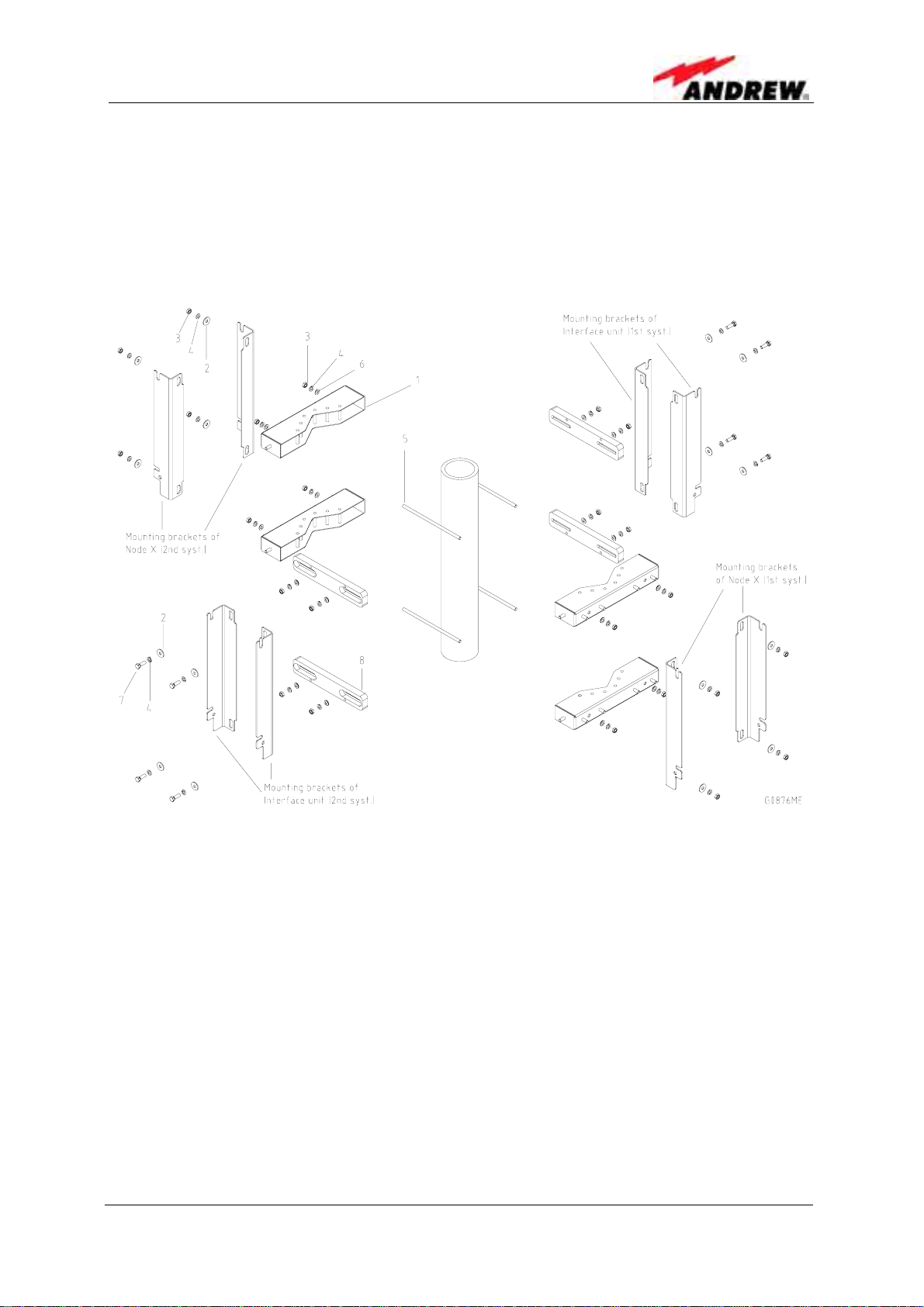
• In case of two systems (figure 3-7) first mount the mounting brackets of the Node
C units; then adjust and mount the fasteners (no. 8) accordingly before fastening
the mounting brackets of the Interface Units to the fasteners.
• Hang the units into the respective mounting brackets and fasten the hexagon
head screws M10x20.
figure 3-7 Pole mounting two systems
ID No: 161692 PRELIMINARY Page 19

3.2 ELECTRICAL INSTALLATION
3.2.1 General
Read the health and safety warnings in chapter 1.2 Health and Safety Warnings.
1. This unit contains dangerous voltages. Loss of life, severe personal
injury or property damage can be the result if the instructions contained
in this manual are not followed.
2. It is compulsory to ground the unit before connecting power supply. A
grounding bolt is provided on the cabinet to connect the ground bonding
cable.
3. Although the unit is internally protected against overvoltage, it is
strongly recommended to earth the antenna cables close to the unit’s
antenna connectors for protection against atmospheric discharge. In
areas with strong lightning it is strongly recommended to insert
additional lightning protection.
User’s Manual for Node C Network Elements
4. Hard wired installation of mains supply for the unit requires an easily
accessible separation device in the mains circuit.
5. Make sure that an appropriate circuit breaker and an overcurrent limiting
device are connected between mains and the unit.
6. A connection of mains supply to a power socket requires the power
socket to be nearby the unit.
7. The unit might be supplied from IT mains. (The maximum nominal line to
line voltage must not exceed 400VAC).
8. Incorrectly wired connections can destroy electrical and electronic
components.
9. To avoid corrosion at the connectors caused by electrochemical
processes, the material of the cable connectors must not cause a higher
potential difference than 0.6V (see electrochemical contact series).
10. It is sufficient to tighten the 7/16 or N antenna connector hand-screw ed.
Any use of a tool (e.g. pair of pliers) might cause damage to the
connector and thus lead to malfunctioning of the unit.
11. For unstabilized electric networks which frequently generate spikes, it is
advised to use a voltage limiting device.
12. The unit complies with the surge requirement according to EN 61000-4-5
(fine protection), however, it is recommended to install an additional
medium (via local supply connection) and/or coarse protection (external
surge protection) depending on the individual application in order to
avoid damage caused by overcurrent.
13. Observe the labels on the front panels before connecting any cables.
Page 20
M0121A1A_uc.doc

3 Installation
3.2.2 Grounding
Grounding the Node C and Interface Unit is mandatory. Connect an earth bonding
cable to the grounding connections provided at the cabinets of both the Node C and
Interface Unit according to the following illustrations.
Do not use the grounding connections to connect external devices.
Cable bridge connectors
Node C cabinet
Cabinet of
Interface Unit
figure 3-8 Grounding bolts
figure 3-9 Grounding a system
The PE cables must have a minimum cross section of 10mm2.
ID No: 161692 PRELIMINARY Page 21
3.2.3 Power Connection
Before connecting electrical power to the units, the system must be grounded as
described in the previous chapter.
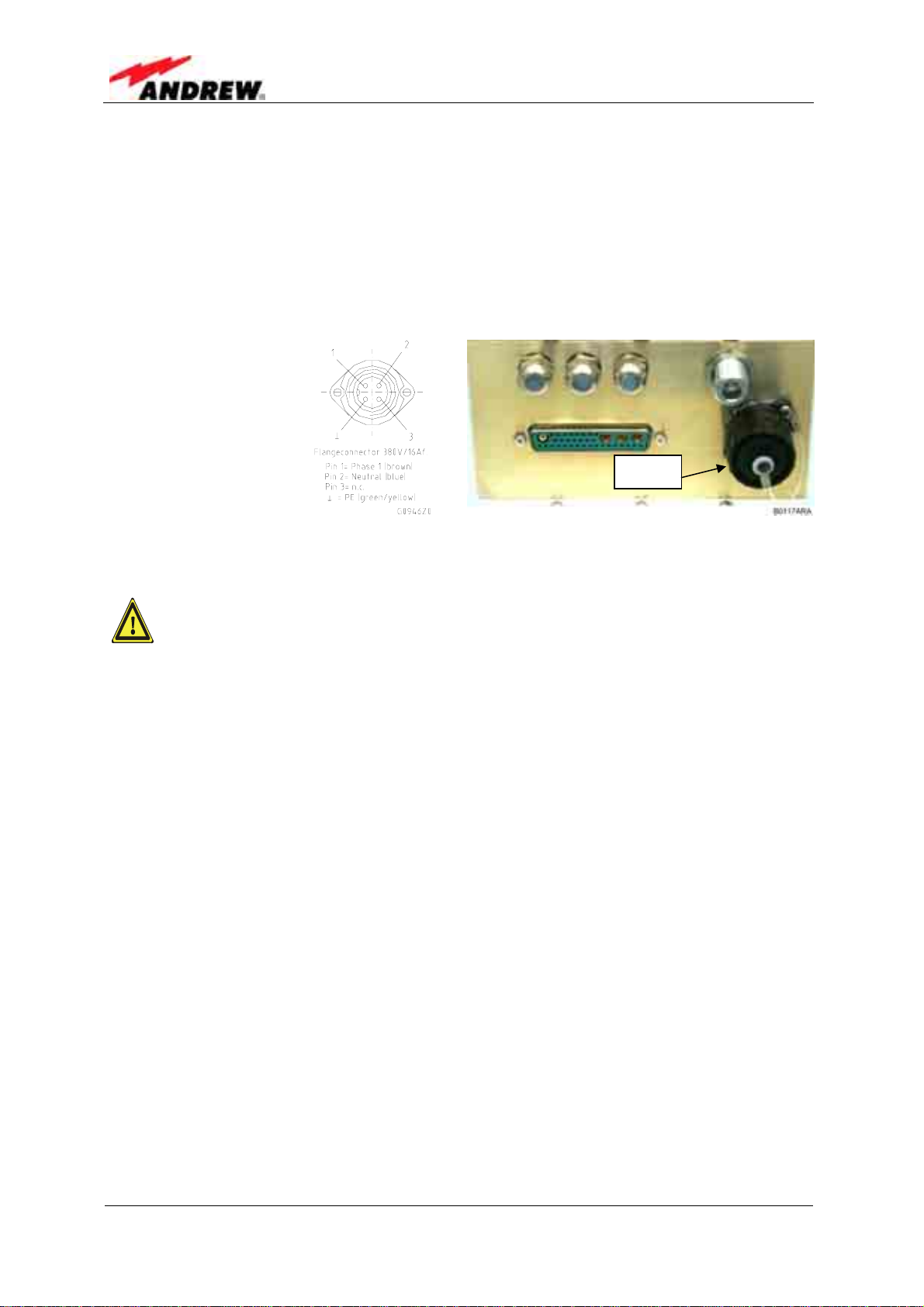
Mains power must be connected at the mains connector of the Interface Unit. The
power supply plug is included with the Node C.
The correct wiring
of the power supply
plug is as follows:
User’s Manual for Node C Network Elements
Mains
figure 3-10 Power supply plug figure 3-11 Mains connector
A minimum cross section of 1.5 mm2 is required for the power supply
connection. Each wire must observe the applicable national regulations
regarding loop impedance, voltage drop, and methods of installation.
Make sure to connect the correct voltage to the unit.
) Note: Do not connect or disconnect the power cord at the mains connector
while power is on. Turn off mains* power before connecting the
power cord at the Interface Unit, then, engage mains again.
* Mains power must be interrupted with an external AC breaker. For the AC breaker,
observe the following recommendation:
120 Volt / 20 Amp max. or 240 Volt / 16 Amp, single-phase, 50/60 Hz AC service is
needed, i.e. the external AC breaker should be 20 Amps max. for 120-Volt service or
16 Amps for 240-Volt service.
Page 22
M0121A1A_uc.doc
3 Installation
3.2.4 Connection of the Antenna Cables
The Node C’s antenna connectors are 7/16 female equipped with an N female
adapter. All connectors are located at the bottom of the cabinet. An operator should
refer to the documentation of the cable connector manufacturer for best mating
procedures. Furthermore, the bending radius of the antenna cables should be
maintained at all times.
There are several issues to be considered when selecting the cable and antenna
types.
• Smaller diameter cables are less expensive and easier to install but have
worse performance.
• Highly directional antennas with good front-back-ratios (40 dB is typical) are
recommended because they improve isolation and cell site selectivity.
Tighten the 7/16 or N connectors ONLY by hand. The use of pliers may cause
damage to the connector and impair the performance of the Node C.
Primary Diversity
Coverage antenna (to mobile) Donor antenna (to base station)
figure 3-12 Front view of antenna connections
3.2.5 Connection of Cable Bridge
The Interface Unit and the Node C are connected via a cable bridge. The bridge
ports 12V, 28V, ground, USB, and RS232 between the two units as well as the
general alarming and signalling. It is also the interconnection and intercommunication
bus between the units.
ID No: 161692 PRELIMINARY Page 23

User’s Manual for Node C Network Elements
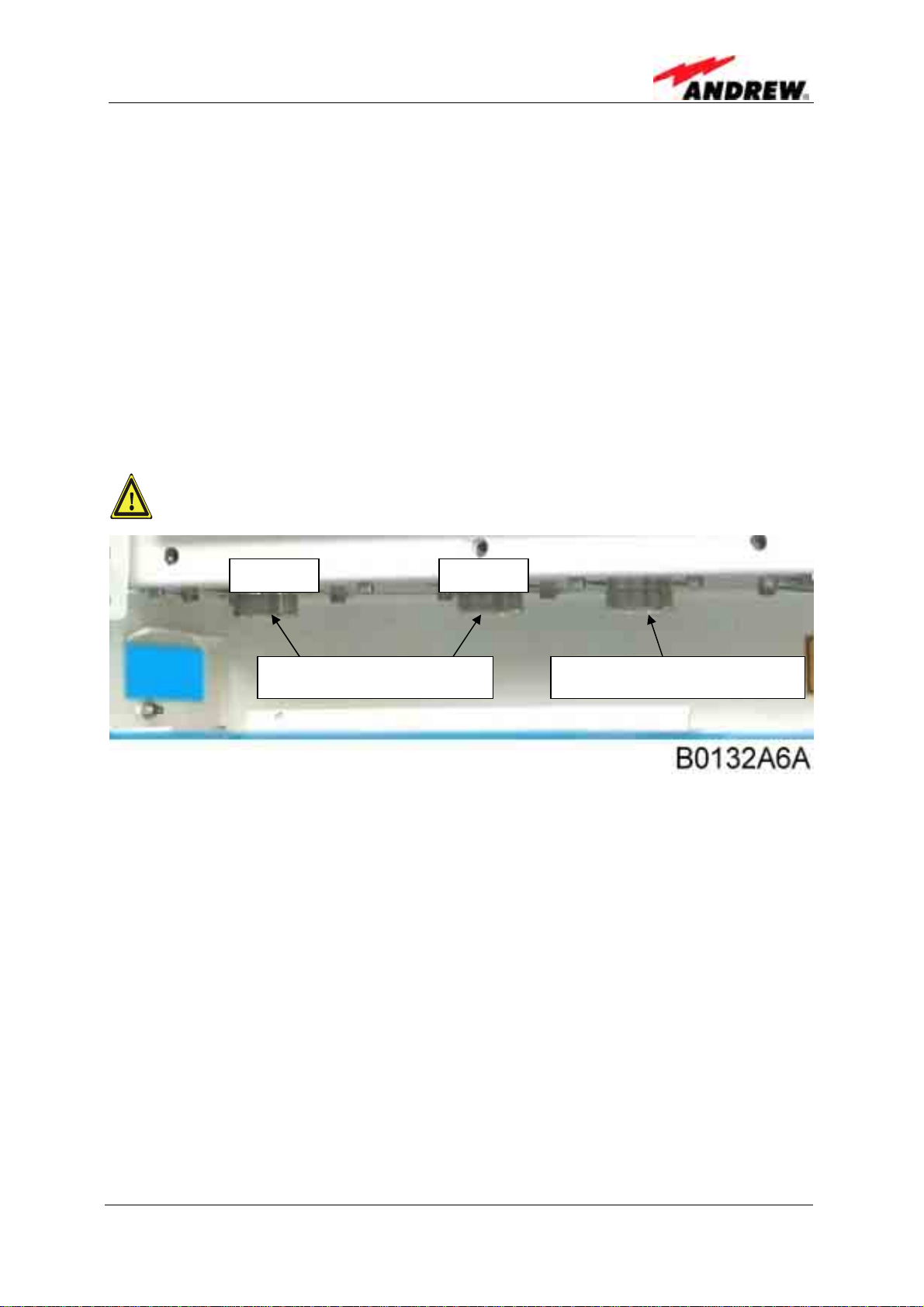
The cable bridge connectors are located at the bottom of the Node C and Interface
Unit.
Cable bridge connector
Antenna connnectors
figure 3-13 Connector panel of the Node C
Antenna
connector
for modem
(operating
in different
network)
Cable glands for external alarms, summary alarm & PSTN
Cable bridge connector
Mains power
connectors
figure 3-14 Connector panel of the Interface Unit
3.2.6 Connections for Optional Equipment
The Interface Unit connector panel has ports for external equipment, such as a
modem operating in a different network and external alarms. These connectors may
be used entirely at the operator’s discretion.
Page 24
M0121A1A_uc.doc
4 Commissioning
4 COMMISSIONING
4.1 GENERAL
Read the health and safety warnings in chapter 1.2 Health and Safety Warnings and
observe the following step-by-step procedure.
• Do not operate the Node C without terminating the antenna connectors. The
antenna connectors may be terminated by connecting them to their respective
antennas or to a dummy load.
• Only qualified personnel should carry out the electrical, mechanical,
commissioning, and maintenance activities that require the unit to be powered
on when open.
• When opening the Node C or interface box do not damage the warranty labels
on the internal devices. The warranty is void if the seals are broken.
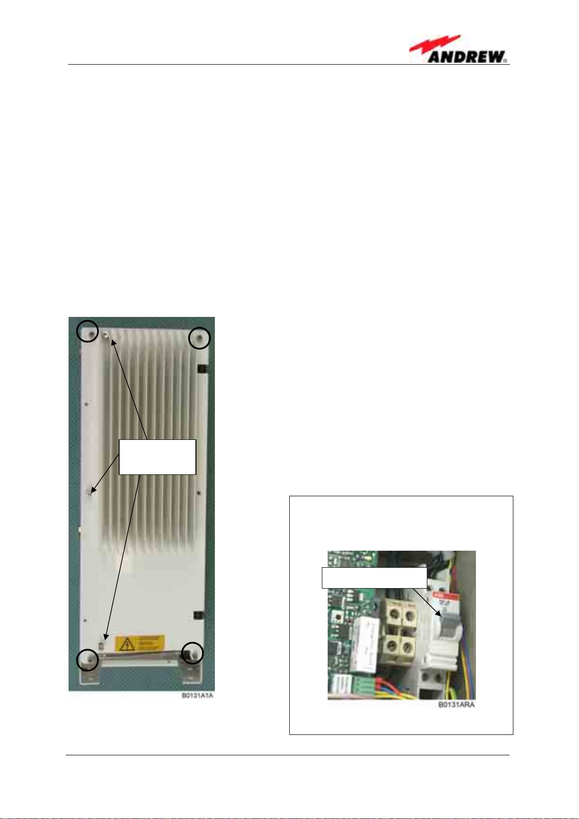
To open the cabinet of the Interface Unit, first remove
the front cover plate by loosening the four M5 socket
head cap screws (circle-marked in figure to the left).
Do not remove those screws. When they are
loosened, the front cover plate can be taken off.
To open the housing, unscrew the three M5 socket
head cap screws (captive) of the top cover of the
Interface Unit.
Three top
cover screws
) Note: Do not forget to reinstall the front
cover afterwards to ensure safe
operation.
) Note: Before closing the Interface
Unit, make sure that the mains power
switch inside is set to On:
Mains power switch
figure 4-1 Front and top cover screws figure 4-2 Position of mains power switch
ID No: 161692 PRELIMINARY Page 25

4.2 SOFTWARE SETUP
4.2.1 Remote Control
For remote control and/or supervision of the Node C the following services are
provided:
• An OMC-type software platform (see separate manual)
• SMS alarm-forwarding (for details see chapter 5.2.5 Alarmforwarding)
• Web page (see chapter 4.2.4 and online-help)
4.2.2 Connection Devices
To connect to the Node C, the following devices are available:
• Locally, via the RS232 interface of the distribution & alarm board of the Interface
Unit (see figure 5-15) using either the connected USB cable or the null modem
cable which is part of the delivery for the connection of a PC or laptop.
• Remotely, if the optional modem is installed in the Interface Unit. All local
commands may be issued via the web interface over the remote modem.
User’s Manual for Node C Network Elements
4.2.3 Connection Procedures
4.2.3.1 Setup Overview
Four steps are required to set up a connection to the Node C.
1. Install the USB to serial adapter in the computer. The USB adapter is part of
the delivery and is already connected to the RS232 connector of the
distribution & alarm board (see figure 4-3). For the first connection, install the
correct driver from the CD (see chapter 4.2.3.2 Installing the USB driver). For
the connection via null modem cable, disconnect the USB connector from the
RS232 connector (see figure 4-3) and connect the null modem cable.
2. Configure the connection device, i.e. RS232/USB/modem. (See section a) of
chapter 4.2.3.3, 4.2.3.4, or 4.2.3.5 depending on the operating system.)
3. Setup a connection:
a) Direct connection via PC or laptop: similar to connecting a computer to a
standard Internet service provider (ISP); see section b) of chapter 4.2.3.3
or 4.2.3.5 depending on the operating system.
b) Modem connection; see section b) of chapter 4.2.3.4.
4. Establish the connection; see section c) of chapter 4.2.3.3, 4.2.3.4, or 4.2.3.5
depending on the operating system.
The following instructions are for Windows XP and Windows 2000. This procedure
must be done only once with the first setup.
Page 26
M0121A1A_uc.doc
4 Commissioning
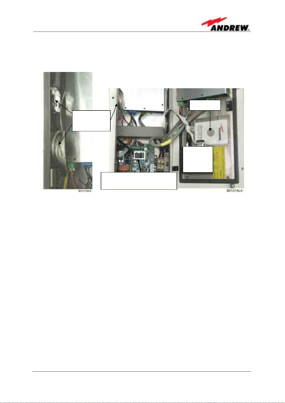
4.2.3.2 Installing the USB driver
The USB adapter and the driver CD are located inside the Interface Unit:
Driver CD
USB adapter
with USB
cable
Position of
optional
modem
RS232 connector for USB or
null modem cable connection
figure 4-3 USB and null modem cable connection
When the USB adapter is connected to a PC for the first time, the USB driver must
be installed. The Node C and Interface Unit must be switched on for the procedure.
To install the driver, proceed as follows:
• Connect the USB cable of the USB adapter to the USB port of the PC.
• Then, wait until the system (valid from Windows98ME) deliv ers the message that
a new USB device was found and asks for the driver.
• Put the CD into the CD-ROM drive of the PC and the system will ask how to
search for the driver.
• Select the automatic search (usually default), confirm, and wait while the system
searches for the driver.
• The successful installation will be informed by a message that the new hardware
was successfully installed.
• After confirming this message the CD can be taken out of the drive and put back
into the plastic cover inside the Interface Unit.
• Reboot the PC.
When the connection is made the next time, this procedure is no longer necessary.
ID No: 161692 PRELIMINARY Page 27
User’s Manual for Node C Network Elements
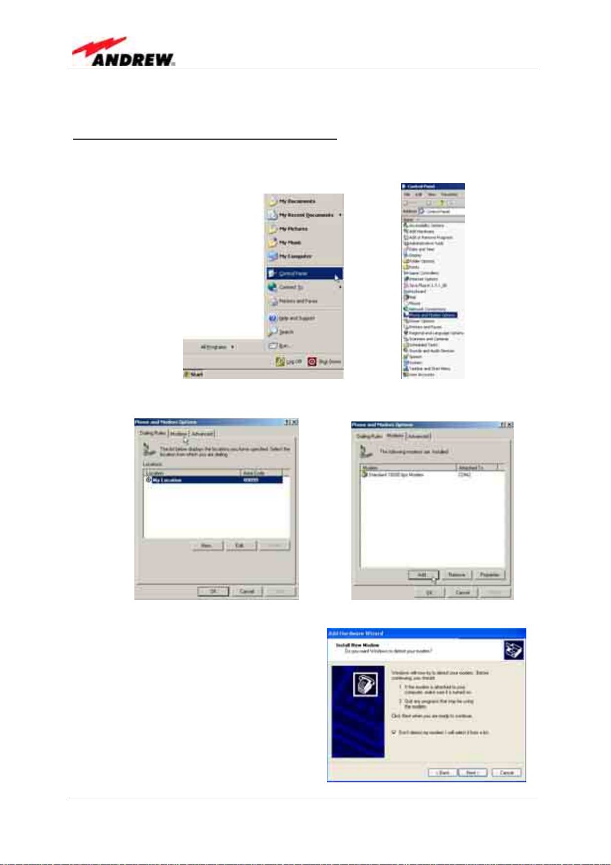
4.2.3.3 Direct connection for Windows XP
a) Setting up the device for the direct connection
1. To start the Phone and Modem Options, choose Start→Control Panel→Phone
and Modem Options.
2. Select the Modems tab and clic k the Add... button.
3. Choose to select from a list.
Click Next.
Page 28
M0121A1A_uc.doc
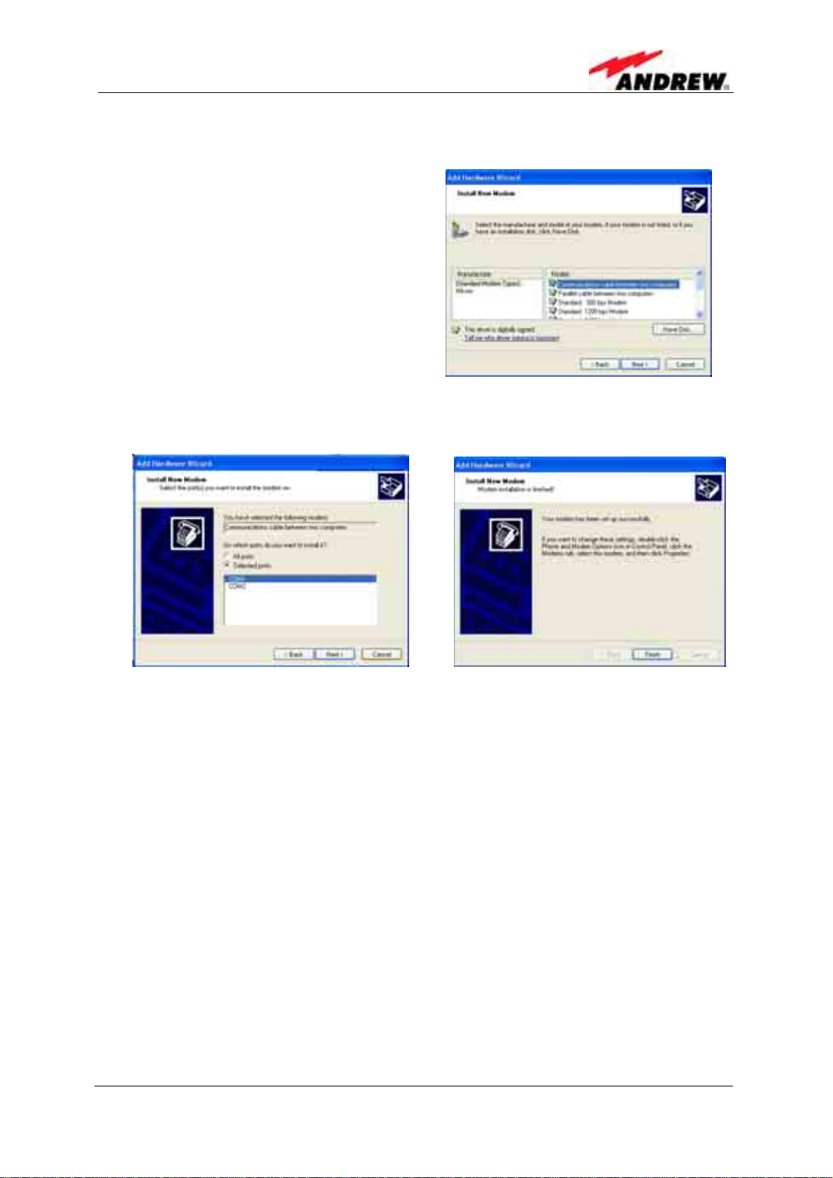
4 Commissioning
4. For a direct connection choose the Communication cable between two
computers as device.
Click Next.
5. Select your port (usually COM1 for a direct connection), continue with Next, and
in the next window click Finish.
ID No: 161692 PRELIMINARY Page 29
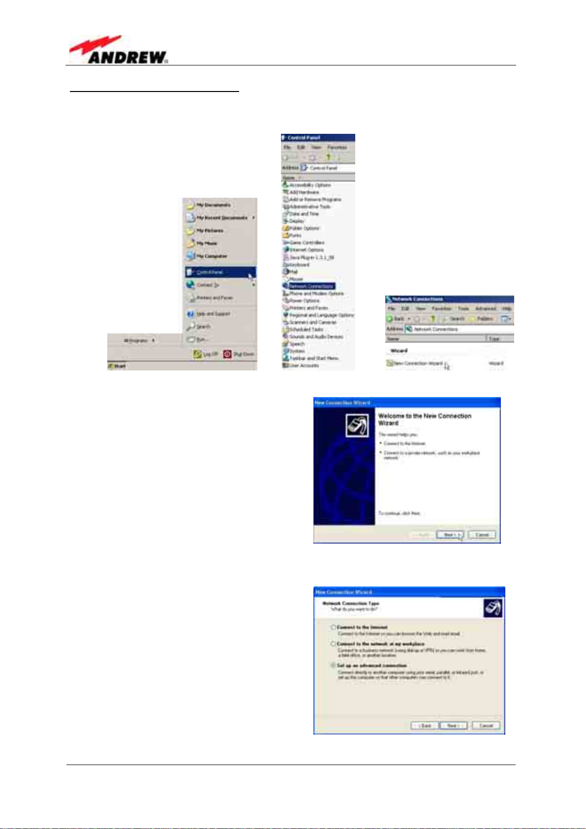
b) Setting up a direct connection
1. Choose Start→Control Panel→Network Connections→New Connection
Wizard.
User’s Manual for Node C Network Elements
2. The first page is the Welcome window:
Continue with Next.
3. In the Network Connection Type window, select Set up an advanced
connection.
Click Next.
Page 30
M0121A1A_uc.doc
 Loading...