

Page 1

OPERATION MANUAL
Model A-22
Head and Combo
08/10
Page 2

2
Page 3

Thank you for purchasing an Andrews Amplifier. The Model A-22 is
built to the highest standards of craftsmanship and is finely tuned
for the ultimate tone. This amp is very simple to operate but we
suggest reading this short manual in order to get the most from your
new amp.
3
Page 4

FEATURES;
• ALL TUBE CIRCUITRY PURE WARM TUBE SOUND – Your guitar signal
does not pass through any transistors or integrated circuits (ICs). We
have also avoided using any relays or other switching devices so nothing
interrupts your pure guitar signal.
• ALL HAND-WIRED CONSTRUCTION – Also sometimes called “point-to-
point” wiring, the A-22 utilizes a very high quality turret board made of
super-tough G10 composite. This glass-epoxy laminate is specified for
its extremely high strength and high dimensional stability over
temperature. The extra-thick board material will never warp, melt, or
absorb moisture and there are no copper traces to peal away from the
board over time. All wiring and soldering is done by hand and quality
checked to ensure many years of trouble free operation.
• CUSTOM-WOUND, AMERICAN-MADE TRANSFORMERS – These
transformers are built to our specifications specifically for the
requirements of this amp design. They are wound on paper bobbins like
in “the good old days” and are rated to withstand extreme heat for high
reliability. In addition, a special type of steel core is utilized for maximum
efficiency, lighter weight and superior tone. The output transformer is
interleaved for optimum balance. Output impedance is switchable to 4, 8
or 16 ohms and 2 speaker jacks are provided.
• CUSTOM DESIGNED CHASSIS – Our chassis is designed specifically for
this amp model so that every part can be mounted in the optimal location
for lowest noise and highest stability.
• CUSTOM DESIGNED CABINET – Our cabinets are specially designed for
maximum durability and superior tone. We use very high-grade void-free
Baltic Birch ply for our cabinets. The cabinet components are precision
cut using high-tech equipment and are hand assembled with care.
Dovetail joints are used at the corners for maximum strength. The combo
cabinet features a 3-piece back that can be configured as closed-back or
semi-open to allow for even more tonal versatility. Unlike most other
combo amps, the speaker compartment is isolated from the tubes. This
greatly reduces the chances of the tubes being vibrated by the sound
pressure waves coming off the back of the speaker therefore reducing
tube microphonics, rattling and premature failure.
• EXTERNAL BIAS TEST POINTS – The A-22 is equipped with external bias
test points and an externally accessible adjustment control. This makes
output tube replacement fast and economical. In fact, with a low cost
multi-meter you can adjust bias yourself. This can be a real advantage in
case of a tube failure during a performance or recording session. See the
section about the rear panel for more information.
4
Page 5

Warnings and Precautions
Vacuum tubes generate a lot of heat. Do not touch hot tubes. Insure plenty of
ventilation behind the amp. Keep away from curtains and other flammable
objects. Keep the amplifier away from children.
Do not expose your amplifier to rain. Never set any cups, glasses, bottles or
cans of liquid on your amplifier.
Do not use any solvents to clean your amplifier.
Never operate your amplifier without a proper speaker load or damage may
occur. See the section about the rear panel features for more information.
Make sure the amplifier is always properly grounded. Never remove or defeat
the ground pin from your power cord. Always unplug the amplifier before
changing tubes or fuses.
Use only correctly rated fuses. See the rear panel of your amplifier and this
manual for proper fuse ratings.
This amplifier can create high sound pressure levels. Please use proper
hearing protection and/or maintain an adequate distance from the amplifier to
avoid hearing damage.
There are no fuses or other user serviceable parts inside your amplifier. Please
refer servicing to qualified service personnel.
Never insert any tool or other object into ventilation holes, tube sockets or other
openings unless instructed to do so in this manual. Otherwise, you may come
in contact with dangerous high voltages inside the chassis.
5
Page 6
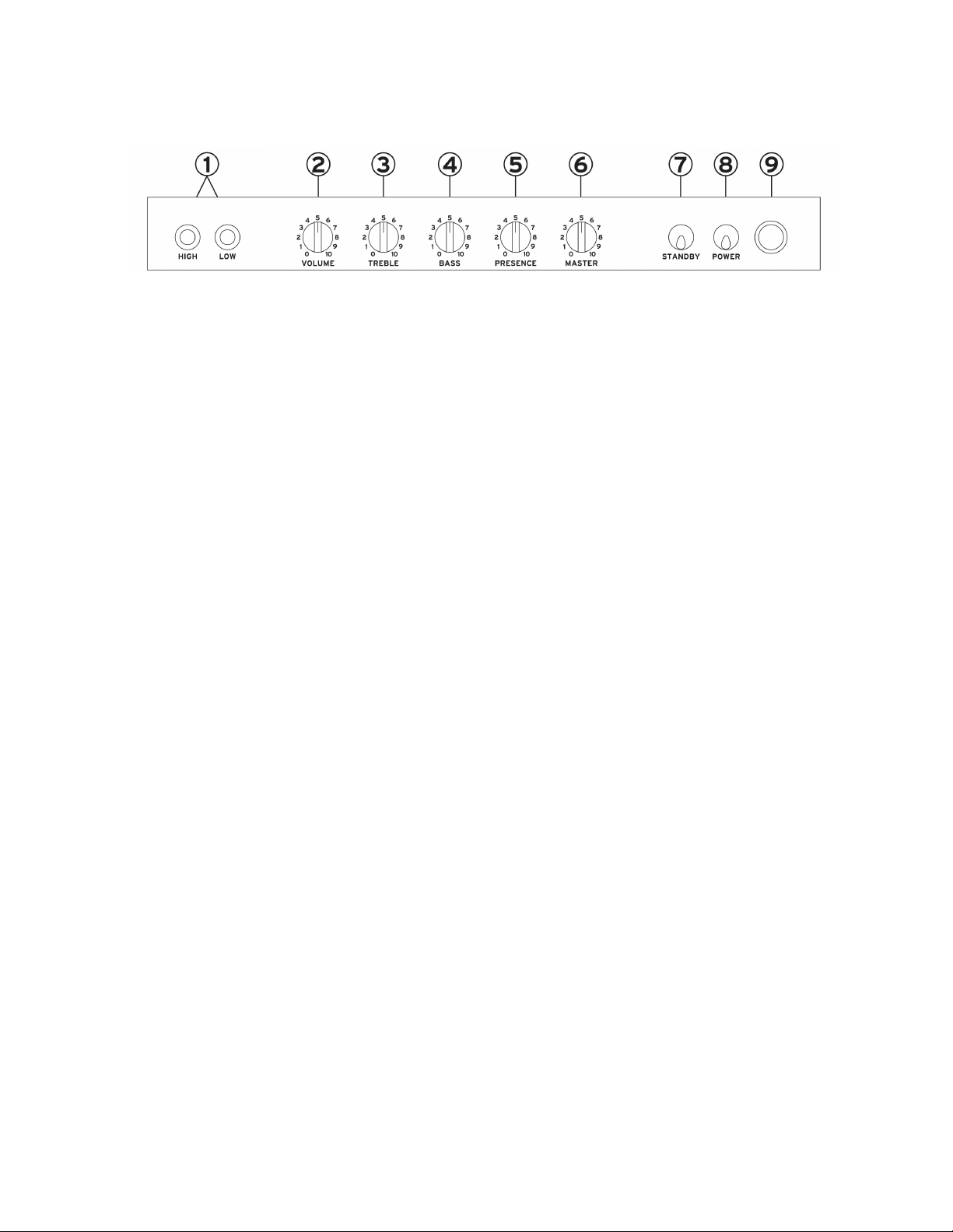
Front Panel
1. INPUT JACKS –
(labeled HIGH and LOW). For maximum overdrive, use the HIGH jack. For a
more usable range of clean and crunch tones, try the LOW jack, especially with
high output pickups or noisy pedal boards. The HIGH jack has 9db more gain
than the LOW jack.
2. VOLUME CONTROL –
or “Input Volume”. It is used in conjunction with the MASTER VOLUME
CONTROL. When the MASTER VOLUME is turned to 10, the VOLUME
CONTROL acts as a standard volume control as if the amp did not have a
MASTER VOLUME CONTROL. That is, when the volume control is turned up,
the amp will give you a nice warm overdriven tone at its maximum volume.
When the MASTER VOLUME is turned lower, you can still get nice overdrive
tones at lower output volume. By using the HIGH or LOW input jack and
adjusting the VOLUME and MASTER VOLUME controls to various positions,
you can fine tune the amount of crunch and overdrive desired at different
volume levels. If you find that you are always setting this control below 5 or 6,
try changing the V1 preamp tube to a 12AU7 (ECC82). This will result in lower
gain and give you a wider range of clean and crunch tones on the VOLUME
control. See the section on Tube Replacement for more details.
3. TREBLE CONTROL -
midrange frequencies. It is most effective when the input volume setting is low.
Use the PRESENCE control to dial in the treble content of overdriven signals
(when the Input VOLUME is turned up).
4. BASS CONTROL –
midrange frequencies.
5. PRESENCE CONTROL –
treble frequencies from your signal and is especially effective when the Input
VOLUME is turned up high and he Master Volume is set to a low level. Crank it
up for a little more bite or back it off for a warmer, smoother tone. By carefully
adjusting the TREBLE and PRESENCE controls, you can vary the balance of
high frequencies for both clean and overdriven tones.
For maximum versatility, we have provided two input jacks
This control could also be labeled “Preamp Gain”
This control varies the amount of treble and upper
This control varies the amount of bass and lower
This control can be used to reduce unwanted
6
Page 7

6. MASTER VOLUME CONTROL –
versatile. Used in conjunction with the VOLUME control and HIGH or LOW
inputs, you can obtain varying levels of overdrive at different volumes. Full
output power can be achieved with at a setting of 8.5 - 10 Try experimenting
within this range to get subtle tonal differences.
7. STANDBY SWITCH –
When turning on the amp, make sure the STANDBY switch is in the off (down)
position. Turn on the POWER (UP position) switch first. The pilot light will light
up. Wait at least 30 seconds to allow time for the tubes to warm up completely
before turning on the STANDBY switch. After the tubes are warmed up, turn
on the STANDBY switch (UP position) to operate the amp. It is a good idea to
turn the STANDBY switch off when not using the amp for more than a few
minutes. This will quite the amp and the stop plate current from flowing in the
tubes, resulting in longer tube life.
8. POWER SWITCH –
Always turn off the POWER SWITCH when not using the amp for several hours
or more.
9. PILOT LIGHT –
bulb replacement, simply unscrew the red lens, grab the bulb with your fingers,
push in while turning counterclockwise and release. Replace with a standard #
47 bulb. For longest life a $755 bulb may also be used. The lens thread fits
many standard lamp lenses and “jewels” allowing you to customize the color if
you desire.
This light indicates when the main power is turned on. For
This switch turns on the high voltage for the tubes.
This switch turns on the main power to the amplifier.
This control is designed to be very
7
Page 8
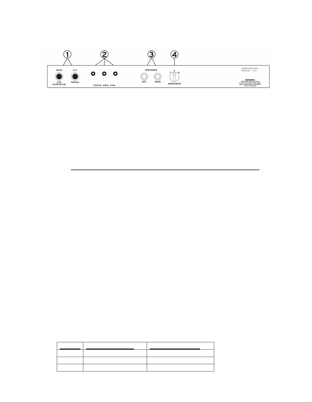
Rear Panel
1. FUSES –
only with a 1.5 Amp “Slow Blow” 250 volt type. The H.V. fuse should be replaced
only with a 500mA (1/2 Amp) fast acting 250V type. Always unplug the AC cord
before changing fuses. When installing a new fuse, first insert it into the cap of the
fuse holder, then while holding only the cap, insert the fuse into the holder, push in
and turn clockwise to lock the cap and fuse in place.
2. BIAS TEST POINTS AND ADJUSTMENT CONTROL
provided for ease of measurement and adjustment of the idle current of the output
tubes. Bias adjustment is necessary whenever the output tubes are replaced.
See page 9 for bias adjustment instructions and precautions. The adjustment
control is located on the underside of the chassis near the test points.
3. SPEAKER JACKS –
cabinet is to be used, meaning that two cabinets will be connected at the same
time, connect the second cabinet to the jack labeled EXT. This amplifier produces
22 watts RMS output power before clipping. When the amp is driven into distortion
at high volume, the output power can exceed 40 watts. Make sure any speakers
you connect can handle the output power of the amp. Always set the impedance
selector switch to match the correct speaker load. See chart below. NEVER
OPERATE THE AMPLIFIER WITHOUT A SPEAKER CONNECTED OR DAMAGE
MAY OCCUR AND THE WARRANTY WILL BE VOID.
Speaker “Break-In” – New speaker cones are tight and stiff. This results in a
brighter tone with less bass and low mids and may even be considered “harsh” at
times. By the time your speaker has been played hard for 20 to 30 hours or more,
its true character and tone will become apparent. Until your speaker is fully
broken-in, you may find that you can achieve better tone by reducing the
PRESENCE and/or TREBLE controls.
4.
IMPEDANCE SELECTOR – Always set this switch to the proper speaker load
according to the chart below. Note: The A-22 combo incorporates a built-in
8 ohm speaker so leave it set to 8 when not connecting another cabinet.
Setting For One Cabinet For Two cabinets
4 One 4 ohm cabinet Two 8 ohm cabinets
8 One 8 ohm cabinet Two 16 ohm cabinets
16 One 16 ohm cabinet
Always use correctly rated fuses. The MAIN fuse should be replaced
– These are
Always use the jack labeled MAIN first. If an additional
8
Page 9

Convertible Cabinet (specific versions
only)
The cabinet back features a removable center-section to allow for more tonal
versatility. When the center-section is left in place, the cabinet will function as a
closed-back speaker enclosure. In this mode, the sound will be more focused or
directional and the bass response will be tighter. When the center section is removed,
the cabinet will function as a semi-open enclosure. The overall volume will be
increased, especially the bass response. In addition, the sound will become less
focused and the bass will sound looser.
As speakers are “broken in” they tend to become looser sounding. This condition will
continue to progress as the speaker is used more and more. Another advantage of
being able to close the back of the cabinet is that it may help to tighten the response
of an aging speaker.
To remove the center section, remove the 10 screws along the top and bottom the
removable portion, being very careful not to press too hard on the screw heads. The
screws are threaded into T-nuts which may push out if too much pressure is applied to
the screws when removing them. If this happens, you may need to hook a pair of
needle nose pliers under the head of the screw and pull outwards on the screw while
turning it to keep the nut from turning. The center panel is designed with gaps at the
ends that are big enough to insert a coin to aid in removing the panel. Also, the panel
is raised slightly so that it can be more easily removed by hand.
When re-installing the center panel, please follow the same precautions regarding
excessive pressure on the screws.
If the back panel is to be removed to replace the speaker, the best option is to remove
just the middle and upper or lower section. This will give you access to the speaker
and should create a big enough opening to allow the speaker to be removed. If the
entire rear panel is removed in one piece, it may be damaged.
9
Page 10

FOR TECHNICAL TYPES
We have provided this information for those who have a technical interest,
proper equipment and proper training in dealing with high voltage circuits.
GUITAR AMPLIFIERS CONTAIN LETHAL VOLTAGES. If you have any doubt
about your ability to safely perform this procedure, refer the job to a qualified
technician!
Bias Adjustment Procedure:
Precautions:
• Lethal voltages are present inside the chassis and at the tube pins. Do not
• Vacuum tubes get very hot. Always allow the tubes to cool completely before
• When replacing output tubes, use only the very highest quality tubes or the
1) Unplug the amplifier and allow the tubes to cool. The output tubes are the two tall
tubes on the left side of the amp when viewed from behind.
2) Unsnap the retaining clips that hold the output tubes in place and remove the
tubes. Install a new matched pair of EL84 or 6BQ5 tubes taking care not to bend
any tube pins. Snap the retaining clips back into position.
3) Using a digital multi-meter, set for DC Volts measurement and select a range that
will show 0-100 mV. Insert the black meter lead into the black test point terminal.
Insert the red meter lead into the left red test point terminal.
4) Insert a small flat blade screwdriver into the adjustment control hole and gently
turn the control to its mid position. The adjustment control is located on the
underside of the chassis near the bias test points.
5) Plug in the AC cord and turn on the amplifier’s main power switch. After waiting at
least 30 seconds, turn on the standby switch. The meter should display a few
millivolts (mV).
6) While taking care not to touch any hot tubes, insert the screwdriver into the
adjustment control and very slowly turn the adjustment until the meter reads
20mV. Turning clockwise will increase the voltage, counterclockwise will reduce
the voltage.
7) Now remove the red meter lead from the test point and insert it into the right red
test point terminal and take a reading. The two terminals are reading a voltage
which represents the idle current of the two output tubes. If you get readings
within 5mV of each other at each test point, the tubes are considered to be
matched. Be sure to adjust the bias so that neither tube idles at more than 20mV.
We have found that the optimum bias point is reached when the tubes test points
read 20mV each but it is ok to set to any voltage from 15mV to 20mV without
causing any damage. Allow the tubes to warm up for at least 5 minutes and
re-check bias. Repeat the adjustment procedure if necessary.
8) It is a good idea to re-check the bias periodically (every 500 hours or so) as the
idle current can drift over time as the tubes age.
open the chassis or insert any objects into any openings other than where
directed by these instructions.
touching them.
amplifier may be damaged. For more details, see the section below regarding
tube replacement.
10
Page 11

TUBE REPLACEMENT
Precautions: Always unplug the amplifier and allow the tubes to cool
completely before touching them.
After years of experience with various available tubes, we have chosen specific tubes
for this amp. This decision has been made for tone and reliability reasons.
You can safely replace any of the three preamp tubes any time without concern about
biasing. ECC803S, ECC83S and 7025 are variations of 12AX7 and are
interchangeable. In the V1 position (far right, looking from the back), a 12AX7 or its
variations will give the maximum amount of gain. The JJ ECC82 (12AU7) also sounds
very nice in the V1 position if less gain is desired. Larger plate tubes such as the
ECC803S or 12AX7LPS work especially well in the V2 and V3 positions. Different
brands will give slightly different tones which may be preferable to some players.
However, some brands have reliability problems and may have more noise,
microphonics or hum.
For output tube replacement, we strongly suggest using JJ brand EL84 tubes. Sovtek
brand EL84s are also reliable and long lasting but may not sound as full and smooth
when new compared to the JJs. This amp applies very high voltages to the output
tubes and lesser quality tubes may not be reliable in this model. Also, it is absolutely
necessary to adjust the bias when replacing the output tubes. Please check our web
site periodically for updates on recommended tube brands since tube production is
constantly changing and new brands are becoming available.
When to replace tubes: 12AX7 preamp tubes will generally last for many thousands
of hours but occasionally problems can development before they “wear out”. If you
hear cracking, popping, ringing, or other strange noises, try replacing your preamp
tubes; one at a time. This may resolve the problem. Also, if you hear a scratchy
sound when turning the VOLUME control, try replacing V2.
Output tubes usually have a somewhat shorter life – They will often start to sound bad
long before they fail. If you notice that your amp is gradually loosing volume,
headroom or “punch”, or if you notice that low notes are sounding a little “flabby”, or
you notice that you are hearing unpleasing harmonics or overtones, it might be time
for a new matched set of high quality output tubes. This could happen after a few
months or it might take several years, depending on how much and how hard the amp
is played. Don’t forget about biasing the output tubes. These symptoms can also be
caused by a worn out speaker so be sure to try the amp on another cabinet to be
sure.
11
Page 12

LIMITED WARRANTY –
Andrews Amp Lab warrants this product to be free of defects in materials and
workmanship for a period of 5 years from the original date of purchase to the original
purchaser. For subsequent owners, the length of warranty shall be for a period of 1
year from the original date of purchase. During the warranty period, in the unlikely
event that a defect occurs, Andrews Amp Lab will at its discretion, repair or replace
the product at no charge to you for parts or labor. You must provide a copy of the
original purchase receipt in order to receive warranty service.
What is covered:
• All components other than vacuum tubes are covered for the periods listed
above.
• Vacuum tubes are covered for a period of 90 days from the original date of
purchase.
What is not covered:
• Any damage due to abuse, accident, improper AC power, lightening, AC power
surge, flood, moisture, rain, solvents and other liquids, fire, smoke, improper
connections, improper bias adjustment, improper service, defective tubes or
normal wear and tear
• Any amp with altered, defaced or removed serial numbers
• Any product that has been altered or modified an any way not authorized in
writing by Andrews Amp Lab Inc.
• Andrews Amp Lab Inc. shall not be liable for any consequential and/or
incidental damages.
How to obtain warranty service: Contact Andrews Amp Lab to arrange for service by
calling 770-671-0485 or e-mailing [email protected]. Check the web at
www.andrewsamplab.com for the latest contact information. After confirming
warranty status, send or bring your amp to the location specified. If shipping, you
are responsible for the cost of getting the amp to us and we will pay the return
shipping costs. Canadian customers are responsible for shipping costs in both
directions.
Copyright 2006, 2007, 2010 Andrews Amp Lab Inc. All Rights Reserved
Valid in USA and Canada only
12
 Loading...