

Page 1
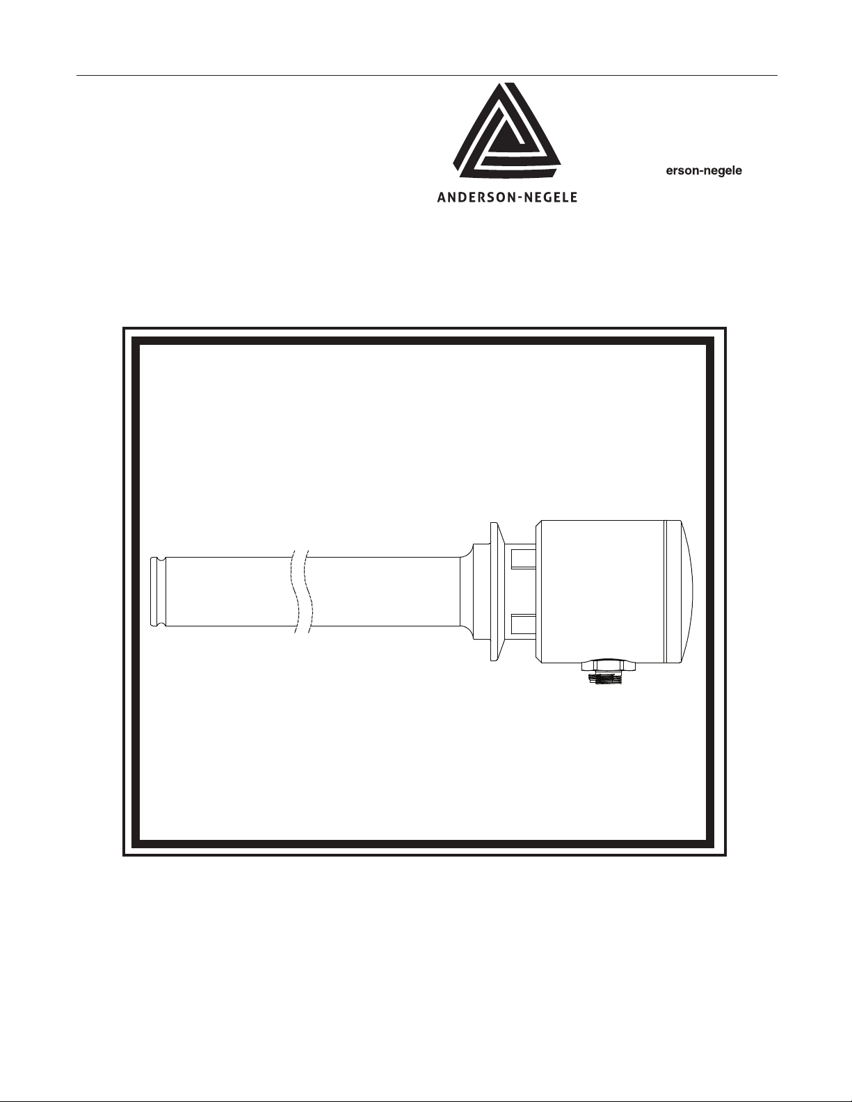
Instruction
Anderson Instrument Co. Inc.
156 Auriesville Road
Fultonville, NY 12072
1-800-833-0081
Fax 518-922-8997
Manual
www.and
Instrument Model Number ________________________________
Instrument Serial Number _________________________________
.com
LD/LA Level TLD/LA Level T
LD/LA Level T
ransmitter
ransmitterransmitter
Form Number AIC2023
© November 2000
Revised: November 2022
Supersedes: March 2009
rettimsnar rettimsnar
Page 2

PAGE 2
Table of Contents
Section 1 - General Page
3NOITCUDORTNI 1.1
3SNOITACIFICEPS 2.1
4NOITPIRCSED 3.1
Section 2 - Installation
5GNITNUOM 1.2
5GNIRIW LACIRTCELE 2.2
7NOITARBILAC "OREZ" CINORTCELE RETTIMSNART 3.2
2.4 CALIBRATION VERIFICATION - UTILIZING ON-BOARD SETUP 8
2.5 CALIBRATION VERIFICATION - UTILIZING EXTERNAL PRESSURE SOURCE 9
11PUTES DRAOB-NO GNIZILITU - NOITARBILAC 6.2
2.7 CALIBRATION - UTILIZING EXTERNAL PRESSURE SOURCE 13
51GNINUT RELLORTNOC 8.2
Section 3 - Maintenance and Troubleshooting
61LARENEG 1.3
61SKCEHC NOITARBILAC 2.3
61METSYS TNEV 3.3
71GNITOOHSELBUORT 4.3
Appendix A - Warranty and Return 18
FIGURES
4gniwarD lanoisnemiD 1-1 erugiF
5weiV noitacilppA lacipyT 1-2 erugiF
6segatloV ylppuS deriuqeR 2-2 erugiF
6margaiD pooL rettimsnarT 3-2 erugiF
7erudecorP noitarbilaC oreZ 4-2 erugiF
8pukooH noitacifireV laC tnerruC 5-2 erugiF
9pmuP erusserP 6-2 erugiF
01pukooH noitacifireV laC erusserP 7-2 erugiF
21pukooH laC dleiF 8-2 erugiF
31pukooH pmuP erusserP 9-2 erugiF
41pukooH laC erusserP 01-2 erugiF
Page 3

Section 1 General
1.1 INTRODUCTION1.1 INTRODUCTION
1.1 INTRODUCTION
1.1 INTRODUCTION1.1 INTRODUCTION
The Anderson “LD/LA” standard and pharmaceutical series level transmitters are unique
devices designed for level control applications where pressure based technology provides
the best overall solution, but where bottom access for the sensor is not available or preferable. These sensors are designed to be mounted on the top of the vessel with the extension
tube positioning the sensing diaphragm near the bottom of the tank. Common applications
include rotary filler bowls, surge tanks and small processing storage vessels where bottom
access is impractical. With no moving parts, no air required, and wide compensated
temperature range the LD/LA provides accuracy and repeatability in applications where
other sensing technologies have been proven unreliable.
1.2 SPECIFICATIONS1.2 SPECIFICATIONS
1.2 SPECIFICATIONS
1.2 SPECIFICATIONS1.2 SPECIFICATIONS
Performance
Upper Range Limit (URL) 72" water column (w.c.)
Minimum Span: 30" w.c.
Over-Range Capacity: 2.5 times the URL (180" w.c.)
Accuracy: ± 0.75% of URL (± 0.5" w.c.)
Repeatability: within ±0.3% of URL (± 0.2" w.c.)
(1) year minimum
Compensated Temp. Range: 30°F to 220°F (-1°C to 104°C)
(process)
Compensated Temp. Range: 30°F to 120°F (-1°C to 49°C)
(ambient)
Effect of Process/Ambient
Temperature Change: ± 0.40% of URL per 10°F
Humidity: 0-100% RH, Condensing
dehsilbup nihtiW:ytilibatS specification for one
PAGE 3
Response Time: 526 mSec
Power Signal
Output: 4-20mA dc
Loop Power required: 12-40 Vdc
Effect of Voltage Change: ± 0.05% of URL per 30 volts
Load Impedance: 1550 Ohms at 40 VDC
Cable Recommended: 18-24 AWG, .169" to .209" diameter,
Materials/Construction
Housing /Wiring Head: 304 stainless steel
Wetted Parts: 316L stainless steel
Surface Finish (LD): Ra=25 microinches or better (wettedparts)
Surface Finish (LA - Pharm.) Ra=15 microinches or better (wetted parts)
Housing Rating: NEMA 4X, IP-65
Approvals
Agency
Electronic "Noise" Designed to meet IEC 801-2, -3 and -4,
Immunity: Level 3, CE Compliant
Sanitary Standards: Complies with all applicable provisions
Hazardous Locations: For LA only: UL, Intrinsically safe for use in CLass 1, Div. 1 Groups A-D.
Warranty: All units are covered by a two (2) year warranty against defects in material
stranded, 2 conductor with ground,
shielded and PVC coated for use with
seal-tight wire grommet
of 3-A Sanitary Standards (74-00).
and workmanship when installed and maintained according to the instruction
manual provided.
Page 4
PAGE 4
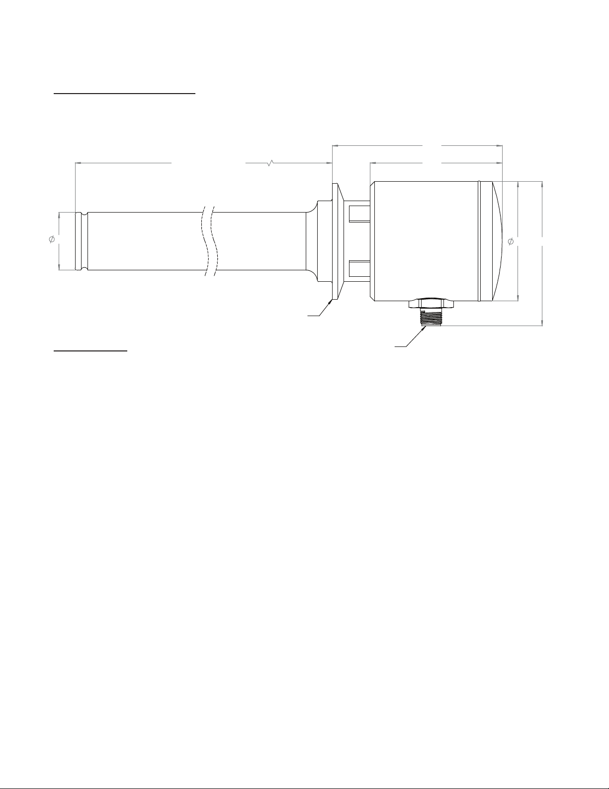
FIGURE 1-1 "LD/LA" DIMENSIONALFIGURE 1-1 "LD/LA" DIMENSIONAL
FIGURE 1-1 "LD/LA" DIMENSIONAL
FIGURE 1-1 "LD/LA" DIMENSIONALFIGURE 1-1 "LD/LA" DIMENSIONAL
DRAWINGDRAWING
DRAWING
DRAWINGDRAWING
SEE MATRIX FOR
AVAILABLE LENGTHS
3.69
2.87
1.25
2" TRI-CLAMP
M12 QDR
1.3 DESCRIPTION1.3 DESCRIPTION
1.3 DESCRIPTION
1.3 DESCRIPTION1.3 DESCRIPTION
The “LD/LA” transmitter has been designed for measuring liquid level in control applications
where a top-mount sensor is preferable or required for optimum performance. Typical
applications include rotating filler bowls, surge tanks, or other atmospheric vessels where
the “dipstick” design makes mounting and wiring simpler than a bottom mount sensor or
other technology.
The LD/LA outputs a standard 4-20mA dc signal for direct connection with a simple
controller or indicator, or to a PLC. Units are calibrated at 0-30 “ w.c. for all lengths between
15” and 30”. For longer lengths, units are calibrated to match the probe length up to the
maximum of 72”. Correction for product specific gravity different than water can be made at
the factory, or in the field using the unique “push button” field calibration feature.
Temperature compensation provides a usable range of up to 220 deg F and is designed to
quickly correct for temperature shocks common in the intended applications. The LD/LA can
be left in place for CIP and sterilization to protect against handling damage.
2.59
3.13
The standard fitting on the LD/LA
of 316 “L” stainless steel.
is a 2” tri-clamp and all wettable surfaces are constructed
Page 5
PAGE 5
Section 2 - Installation
2.1 MOUNTING2.1 MOUNTING
2.1 MOUNTING
2.1 MOUNTING2.1 MOUNTING
The transmitter is designed to be mounted on the process vessel. Connection is secured via
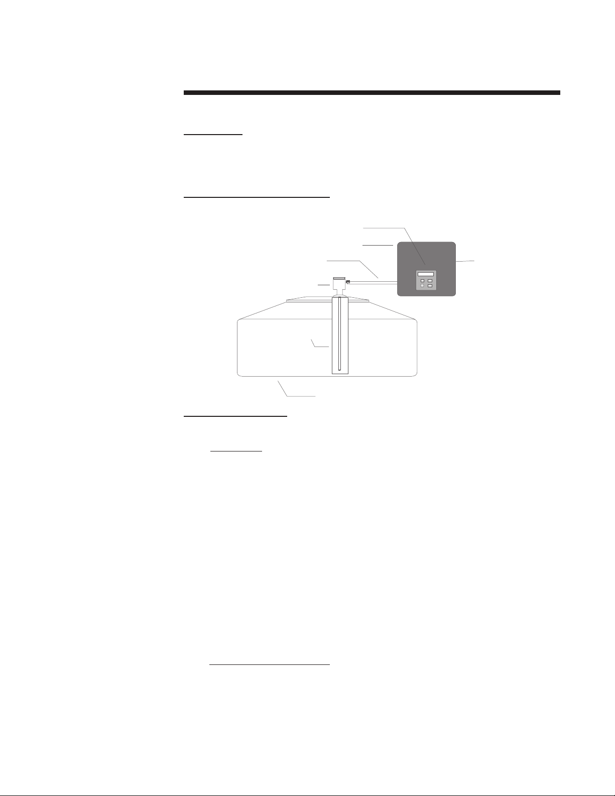
2" Tri Clamp - gasket to be customer supplied. A typical application is as follows:
FIGURE 2-1 TYPICAL APPLICATION VIEWFIGURE 2-1 TYPICAL APPLICATION VIEW
FIGURE 2-1 TYPICAL APPLICATION VIEW
FIGURE 2-1 TYPICAL APPLICATION VIEWFIGURE 2-1 TYPICAL APPLICATION VIEW
PID LOOP CONTROLLER
CONTROL PANEL
ELE CTRICAL WIRING
ELECTRONIC SENSOR
INSIDE VIEW
4-20mA OU TPUT
TO CONTROL VALVE
(or I/P)
FILLER BOWL
2.2 ELECTRICAL WIRING2.2 ELECTRICAL WIRING
2.2 ELECTRICAL WIRING
2.2 ELECTRICAL WIRING2.2 ELECTRICAL WIRING
2.2.1 Signal Cable
Anderson recommends the use of 18-24 AWG, 4 conductor cable. In addition, it should be
foil shielded with a continuous drain wire (If Factory supplied, Belden #9534 or equivalent).
Although only two conductors and the drain wire are utilized, cable as specified above will
retain its roundness when inserted into the seal-tight grommet. This will prevent moisture
from entering the conduit housing of the transmitter. The drain (ground) wire should be
attached to ground at only the receiver end. Be sure that this wire is cut back far enough so
as not to make connection with any stainless steel inside the conduit head of the sensor.
Installation as described will prevent induced ground loop currents from flowing through the
drain wire causing errors in the mA signal.
WARNING: To prevent signal interference, do not run signal cable closer than 12" to
AC wiring, or if you must, cross it at a 90° angle.
NOTE: If using customer supplied cable, be sure it is .109" - .209” O.D.. The use of
larger diameter cable will make entry of the cable into the conduit housing
difficult, while the use of smaller diameter cable may allow moisture to enter the
transmitter.
Transmitter Power and Wiring
2.2.2
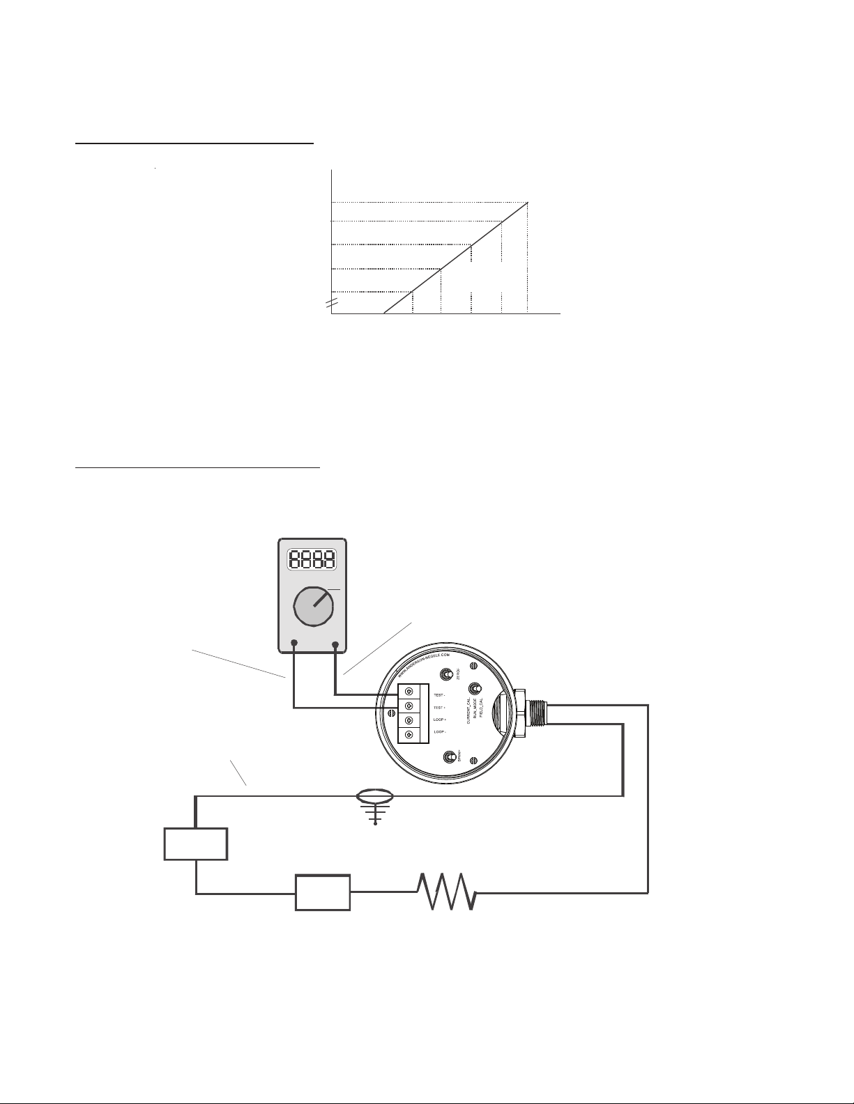
The model LD Level Transmitter requires 12-40 VDC for proper operation. If below 24 VDC,
a regulated supply is recommended. The total loop resistive load (signal wire, signal
receiver, optional display, but not including transmitter) must not exceed the value given in
Figure 2-3 corresponding to the voltage of the DC power supply used. Allow 23.3 ohms per
1000 feet for each conductor of 24 AWG sized wire (the smaller the AWG gauge, the larger
the wire cross section).
Page 6
PAGE 6
FIGURE 2-2 REQUIRED SUPPLY VOLTAGESFIGURE 2-2 REQUIRED SUPPLY VOLTAGES
FIGURE 2-2 REQUIRED SUPPLY VOLTAGES
FIGURE 2-2 REQUIRED SUPPLY VOLTAGESFIGURE 2-2 REQUIRED SUPPLY VOLTAGES
1400
MAXIMUM LOOP
RESISTANCE (OHMS)
(WIRE PLUS RECEIVER)
1200
900
600
300
OPERATING
RANGE
0
9 12 18 24 30 36
POWER SUPPLY VOLTAGE (VDC)
40
It is recommended that the leads be stripped and tinned to provide for optimum signal
connections. Wire to the integral terminal block in the transmitter conduit heads as illustrated
in Figure 2-3.
FIGURE 2-3 TRANSMITTER LOOP DIAGRAMFIGURE 2-3 TRANSMITTER LOOP DIAGRAM
FIGURE 2-3 TRANSMITTER LOOP DIAGRAM
FIGURE 2-3 TRANSMITTER LOOP DIAGRAMFIGURE 2-3 TRANSMITTER LOOP DIAGRAM
HOOK METER TO
TESTPOINTS
FOR CALIBRATION
RED METER LEAD
(TEST+)
M ETE R MODE
SET TO DC MILLIAMP
BLACK M ETER LEAD
(T EST-)
IF FACTORY SUPPLIED CABLE
BELDEN #: 9 534
(GREEN & WHITE NOT USED)
+
SIGNA L
RECEIV ER
-
-
12-40 VDC
POWER
SUPPLY
SHIE LD GROUND
(ONE POINT ONLY)
+
WIRE
RESISTAN CE
LOOP - (BLACK)
LOOP + (RED)
Page 7
PAGE 7
2.3 TRANSMITTER ELECTRONIC "ZERO" CALIBRATION2.3 TRANSMITTER ELECTRONIC "ZERO" CALIBRATION
2.3 TRANSMITTER ELECTRONIC "ZERO" CALIBRATION
2.3 TRANSMITTER ELECTRONIC "ZERO" CALIBRATION2.3 TRANSMITTER ELECTRONIC "ZERO" CALIBRATION
Upon installation of a new Factory Calibrated unit, and as part of routine maintenance, a
Zero calibration adjustment must be performed. The transmitter ZERO, (signal output with
no pressure applied to the diaphragm), is 4.00 mA. Although the calibration may be
performed without additional tools, testpoints have been provided for monitoring the mA
output signal from the transmitter. For maximum accuracy we recommend performing a
sensor zero about three (3) weeks after initial installation, or following several heat/cool
cleaning cycles.
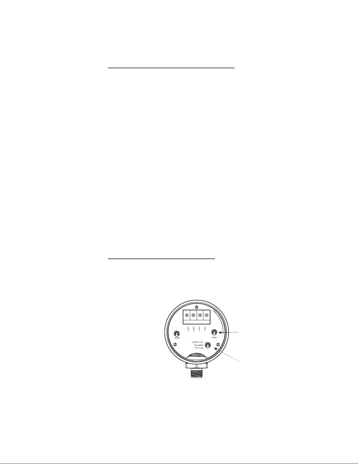
See Figure 2-4, Zero Calibration Procedure, for the location of the Zero switch. Depressing
for 5-8 seconds automatically "zeros" the output.
CAUTION:
• Field wiring MUST be complete – loop power (12-40 VDC) applied
• Transmitter MUST be installed in vessel
• Verify NO product contact to diaphragm
• Vessel MUST be vented to atmosphere
• DO NOT depress SPAN switch
• MODE switch set to RUN MODE
Once Zero calibration has been performed, sensor output will return to 4.00 mA. This is the
proper output to signify an empty vessel – ZERO calibration is complete.
NOTE: No adjustment to the SPAN is necessary. ZERO and SPAN settings are non-
interactive, having no effect on each other.
FIGURE 2-4 ZERO CALIBRATION PROCEDUREFIGURE 2-4 ZERO CALIBRATION PROCEDURE
FIGURE 2-4 ZERO CALIBRATION PROCEDURE
FIGURE 2-4 ZERO CALIBRATION PROCEDUREFIGURE 2-4 ZERO CALIBRATION PROCEDURE
NOTE: RECEIVER AND METER CONNECTIONS
OMITTED FOR CLARITY
REFER TO FIGURE 2-3 FOR HOOKUP
SHOWN WITH
CAP REMOVED
DEPRESS SWITCH
TO INITIATE ZERO CALIBRATION
HOLD FOR 5-8 SECONDS TO
COMPLETE ZERO CALIBRATION
MODE SWITCH
SET TO
ZERO/-
RUN MODE
Page 8
PAGE 8
2.4 CALIBRATION VERIFICATION - UTILIZING ON-BOARD SETUP2.4 CALIBRATION VERIFICATION - UTILIZING ON-BOARD SETUP
2.4 CALIBRATION VERIFICATION - UTILIZING ON-BOARD SETUP
2.4 CALIBRATION VERIFICATION - UTILIZING ON-BOARD SETUP2.4 CALIBRATION VERIFICATION - UTILIZING ON-BOARD SETUP
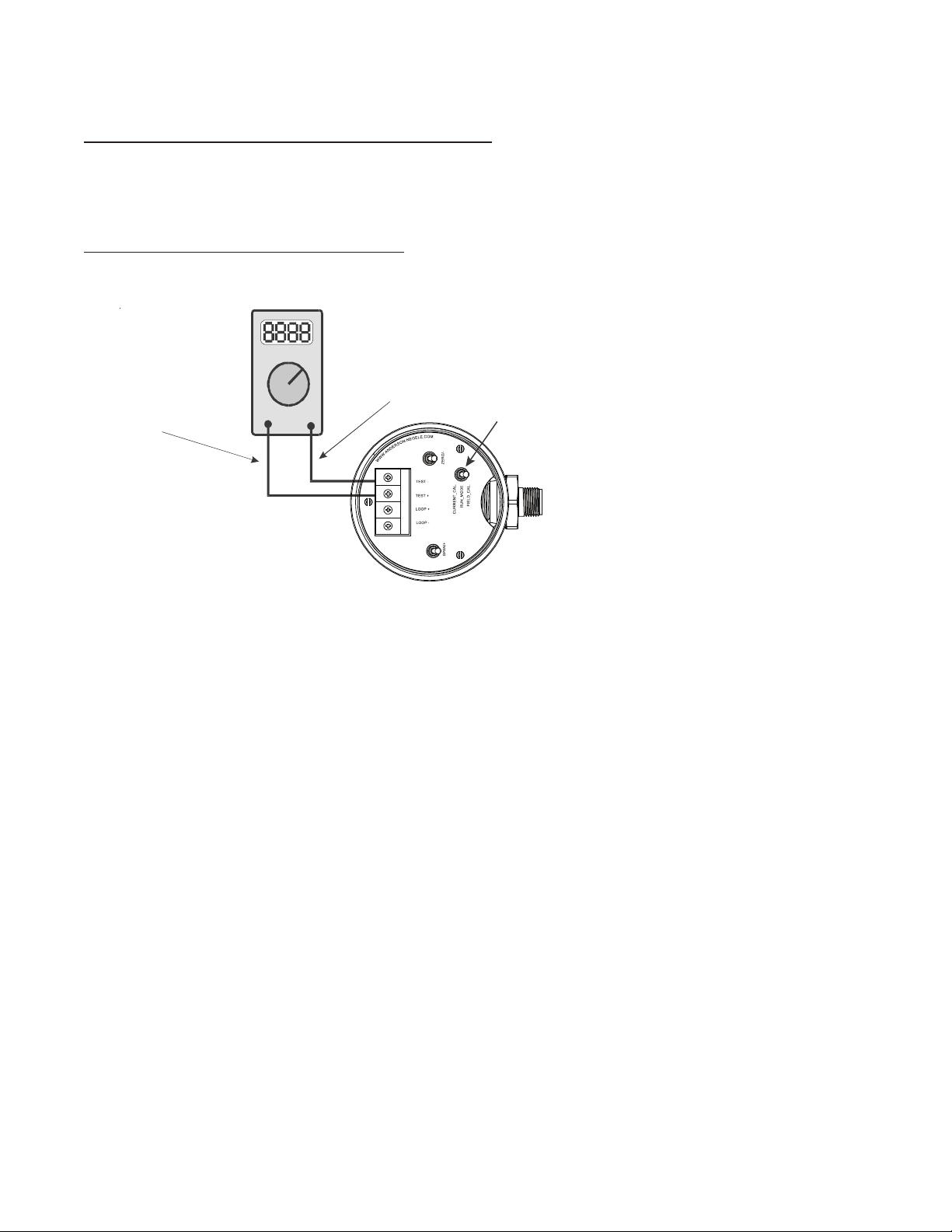
Utilizing a digital multimeter attached to the on-board testpoints, the LD/LA transmitter may be
switched to an alternate output mode where the signal viewed on the meter is proportional to
the current calibration range of the transmitter. Hookup is as follows:
FIGURE 2-5 CURRENT CAL VERIFICATION HOOKUPFIGURE 2-5 CURRENT CAL VERIFICATION HOOKUP
FIGURE 2-5 CURRENT CAL VERIFICATION HOOKUP
FIGURE 2-5 CURRENT CAL VERIFICATION HOOKUPFIGURE 2-5 CURRENT CAL VERIFICATION HOOKUP
HOOK METER TO
TESTPOINTS
FOR CALIBRATION
RED METER LEAD
(
TEST+)
DC mA
METER MODE
SET TO DC MILLIAMP
BLACK METER LEAD
(
TEST-)
Set to
Note: Proper loop wiring must be established,
not shown for clarity
CURRENT CAL
As shown, set operating switch to CURRENT CAL position. The signal displayed on the meter
at this point is directly proportional to the current SPAN setting of the sensor. Using the
following procedure, this value can be converted to the “Inches of Water Column" calibration
value:
• Perform calculation to determine current inches of Water Column calibration
[[Meter Reading – 4.00] ÷ 16] x 145 = Current Cal in "w.c.
• Once calibration has been determined, move switch back to RUN position to
continue operation
• If value determined matches value in model number, unit is properly calibrated
• If value does not match value in model number, sensor calibration has been
altered since unit left the factory – see sections that follow for proper re-calibration
procedures
Page 9
PAGE 9
2.5 CALIBRATION VERIFICATION - UTILIZING EXTERNAL PRESSURE SOURCE2.5 CALIBRATION VERIFICATION - UTILIZING EXTERNAL PRESSURE SOURCE
2.5 CALIBRATION VERIFICATION - UTILIZING EXTERNAL PRESSURE SOURCE
2.5 CALIBRATION VERIFICATION - UTILIZING EXTERNAL PRESSURE SOURCE2.5 CALIBRATION VERIFICATION - UTILIZING EXTERNAL PRESSURE SOURCE
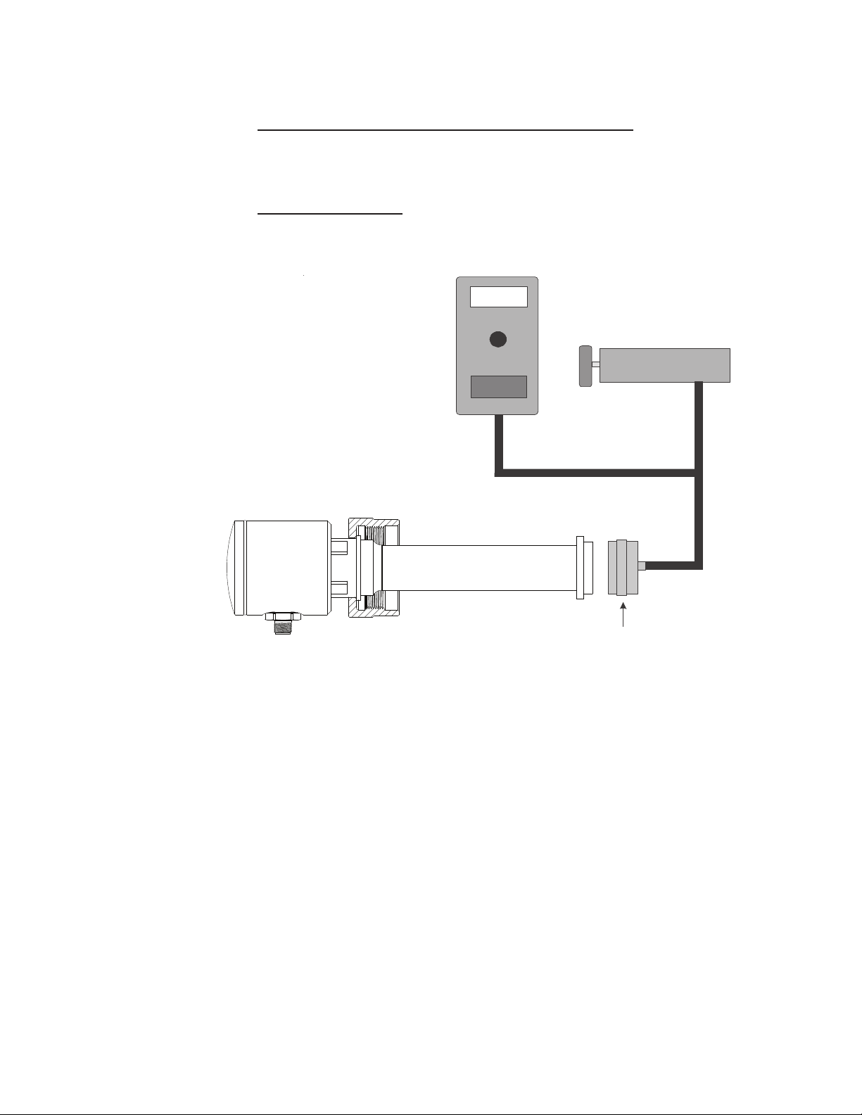
If available, an external pressure calibrator may be used to determine the current calibration of a sensor. Test procedure is as follows:
FIGURE 2-6 PRESSURE PUMPFIGURE 2-6 PRESSURE PUMP
FIGURE 2-6 PRESSURE PUMP
FIGURE 2-6 PRESSURE PUMPFIGURE 2-6 PRESSURE PUMP
HOOKUPHOOKUP
HOOKUP
HOOKUPHOOKUP
Digital Pressure Calibrator
(Suggested Unit)
Crystal Engineering
Phone: 800-444-1850
Model: 212-030PSI-G-HR
Pressure Pump
Snap fit Calibration Adapter
#73198-A3
Page 10
PAGE 10
FIGURE 2-7 PRESSURE CAL VERIFICATION HOOKUPFIGURE 2-7 PRESSURE CAL VERIFICATION HOOKUP
FIGURE 2-7 PRESSURE CAL VERIFICATION HOOKUP
FIGURE 2-7 PRESSURE CAL VERIFICATION HOOKUPFIGURE 2-7 PRESSURE CAL VERIFICATION HOOKUP
HOOK METER TO
TESTPOINTS
FOR CALIBRATION
RED METER LEAD
TEST+)
(
DC mA
METER MODE
SET TO DC MILLIAMP
BLACK METER LEAD
TEST-)
(
Set to
Note: Proper loop wiring must be established,
not shown for clarity
RUN MODE
1. Remove sensor from vessel if already installed – leave loop wiring attached
2. Provide loop power to sensor if performing a bench test
3. Attach snap fit calibration adapter to sensor fitting (Available from Anderson)
4. Sensor MUST remain stationary, with no movement
5. Perform ZERO calibration as described in this manual
6. Set pressure calibrator to proper range
7. Set multimeter to 4-20 mA DC scale, make connections at “TEST +” and “TEST -”
testpoints
8. Using pressure pump, increase pressure until 20.00 mA is seen on the multimeter
9. Read “Water Column” from Pressure Calibrator – this is current sensor calibration
10. If value determined matches value etched on side of sensor, calibration ok
11. If value does not match value in model number, sensor calibration has been altered since
unit left the factory – see sections that follow for proper re-calibration procedures
Page 11

PAGE 11
2.6 CALIBRATION - UTILIZING ON-BOARD SETUP2.6 CALIBRATION - UTILIZING ON-BOARD SETUP
2.6 CALIBRATION - UTILIZING ON-BOARD SETUP
2.6 CALIBRATION - UTILIZING ON-BOARD SETUP2.6 CALIBRATION - UTILIZING ON-BOARD SETUP
LD/LA transmitters utilize on-board "Setup" circuitry to perform maintenance and calibration.
With these tools, in addition to a digital multimeter, it is possible to perform a field calibration / re-calibration of the output range.
Note:
• Use caution if altering factory calibration – no record will exist at Anderson
pertaining to changes
• Calibration MUST remain within range parameters of unit – be sure to refer to
tables provided
• Loop power MUST be supplied to sensor
Tools Required: Digital Multimeter
Calculator
NOTE: When re-calibrating a unit, you must remain within unit FULL OPERATING
RANGE (0- 72" w.c.).
1. Determine Desired Calibration, in Inches of Water Column (“WC)
Example: Height Above Sensor In Inches (32") x
Specific Gravity of Product (1.032) = 33.0"WC
2. Determine Proportional Cal Value for calibration using the following formula:
[[[STEP 1 VALUE ÷ 145] x 16 ] + 4.00] = New Proportional Cal Value
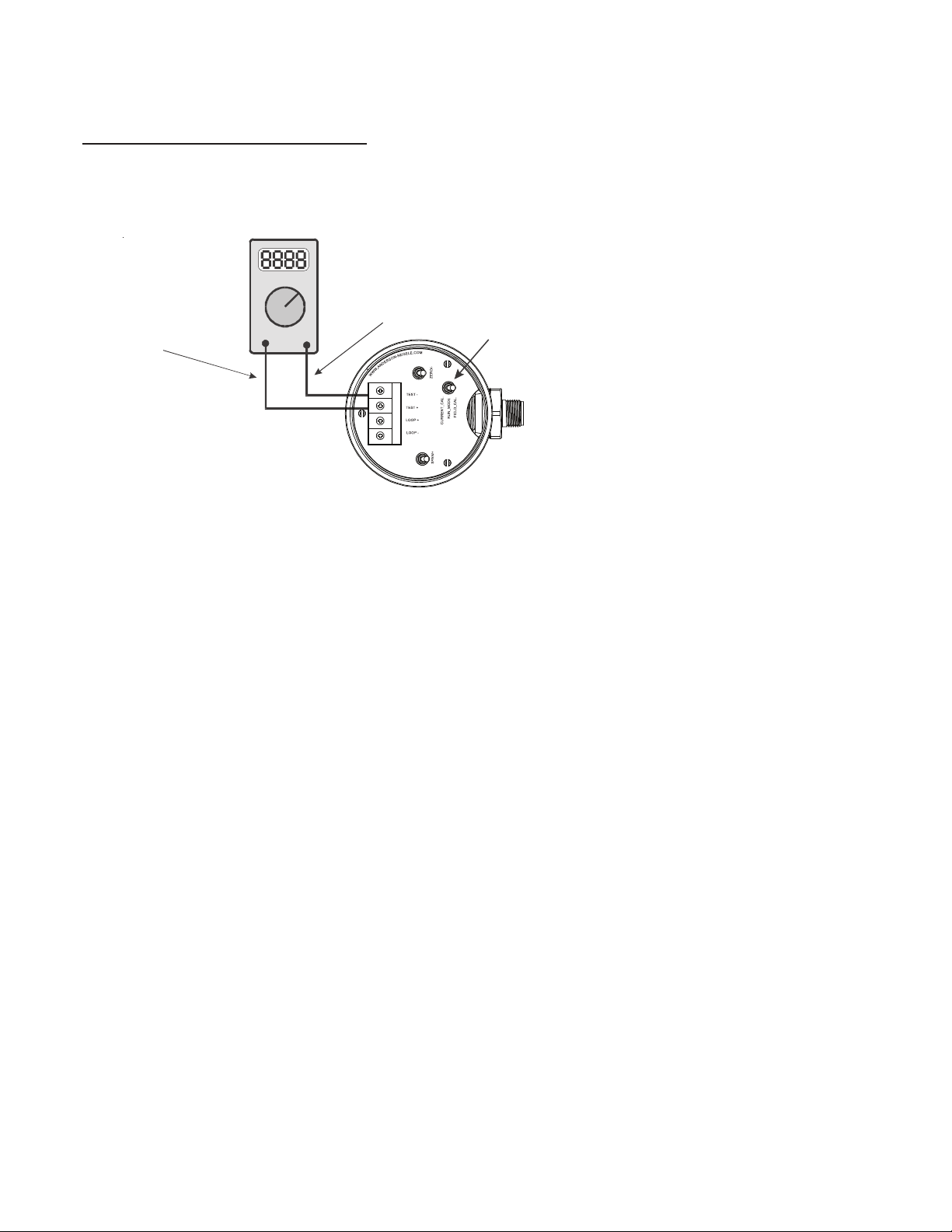
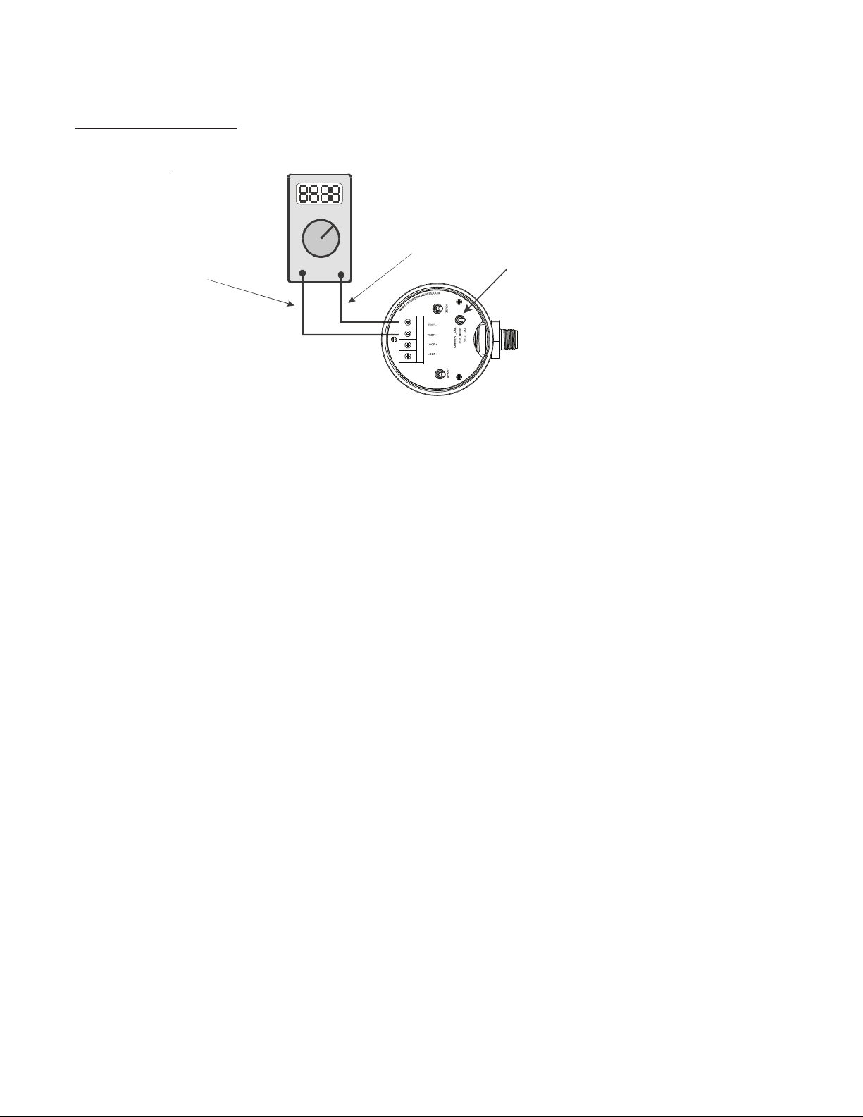
3. Perform meter hookup as shown in the following figure – Set MODE SWITCH to FIELD
CAL position
Page 12
PAGE 12
FIGURE 2-8 FIELD CAL HOOKUPFIGURE 2-8 FIELD CAL HOOKUP
FIGURE 2-8 FIELD CAL HOOKUP
FIGURE 2-8 FIELD CAL HOOKUPFIGURE 2-8 FIELD CAL HOOKUP
HOOK METER TO
TESTPOINTS
FOR CALIBRATION
RED METER LEAD
TEST+)
(
DC mA
METER MODE
SET TO DC MILLIAMP
BLACK METER LEAD
TEST-)
(
Set to
Note: Proper loop wiring must be established,
not shown for clarity
FIELD CAL
4. Meter output will automatically move to 19.99 – sensor is waiting for entry of new calibration range
5. SPAN switch secondary function is “+”, and the ZERO switch secondary function is “-”
6. Using these two switches, raise or lower the value currently displayed on the meter until
the value determined in step three (3) has been reached
7. Once the proper value has been reached, simultaneously depress BOTH the SPAN/+ and
the ZERO/- switches for one (1) second – this will lock in new sensor calibration
8. Calibration complete - mode switch set to "RUN MODE" position - place unit back into
vessel - perform "ZERO" calibration
Page 13
PAGE 13
2.7 CALIBRATION - UTILIZING EXTERNAL PRESSURE SOURCE2.7 CALIBRATION - UTILIZING EXTERNAL PRESSURE SOURCE
2.7 CALIBRATION - UTILIZING EXTERNAL PRESSURE SOURCE
2.7 CALIBRATION - UTILIZING EXTERNAL PRESSURE SOURCE2.7 CALIBRATION - UTILIZING EXTERNAL PRESSURE SOURCE
If available, an External Pressure Calibrator may be used to perform a field calibration / recalibration of the range on the LD/LA Series Transmitter.
Note:
• Use caution if altering factory calibration – no record will exist at Anderson
pertaining to changes
• Calibration MUST remain within range parameters of unit – be sure to refer to
tables provided
• Loop power MUST be supplied to sensor
Tools Required: Pressure Calibrator (Equivalent to unit as described)
Digital Multimeter
1. Determine that the desired range is within Full Operating Range of sensor (72" w.c.)
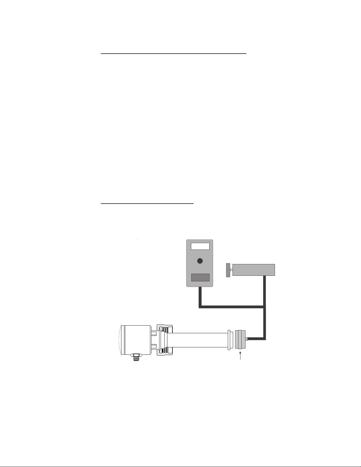
2. Perform hookup of pressure calibrator as shown in the following figure – orient sensor in
a location where easy access may be made to the internal setup switches
3. Perform hookup of Multimeter as shown in the figure on the following page:
FIGURE 2-9 PRESSURE PUMP HOOKUPFIGURE 2-9 PRESSURE PUMP HOOKUP
FIGURE 2-9 PRESSURE PUMP HOOKUP
FIGURE 2-9 PRESSURE PUMP HOOKUPFIGURE 2-9 PRESSURE PUMP HOOKUP
Digital Pressure Calibrator
(Suggested Unit)
Crystal Engineering
Phone: 800-444-1850
Model: 212-030PSI-G-HR
Pressure Pump
Snap fit Calibration Adapter
#73198-A3
Page 14
PAGE 14
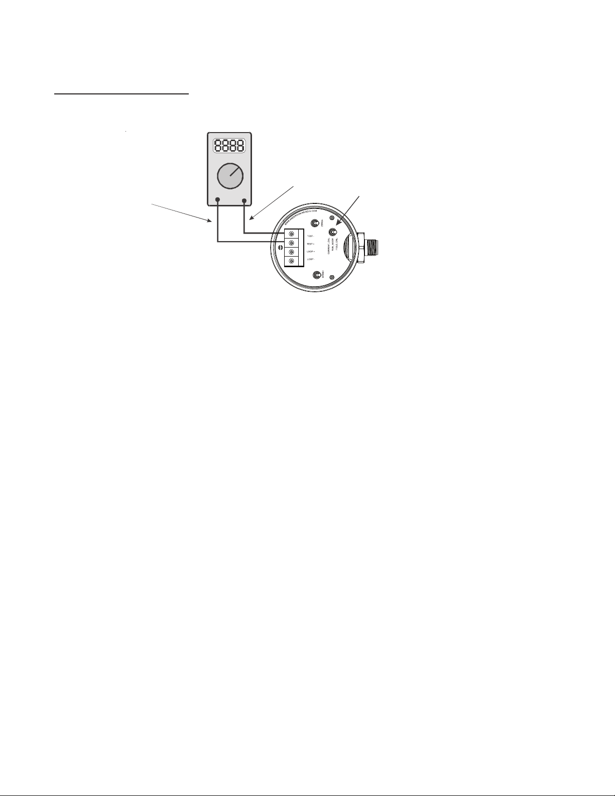
FIGURE 2-10 PRESSURE CAL HOOKUPFIGURE 2-10 PRESSURE CAL HOOKUP
FIGURE 2-10 PRESSURE CAL HOOKUP
FIGURE 2-10 PRESSURE CAL HOOKUPFIGURE 2-10 PRESSURE CAL HOOKUP
HOOK METER TO
TESTPOINTS
FOR CALIBRATION
RED METER LEAD
(
TEST+)
DC mA
METER MODE
SET TO DC MILLIAMP
BLACK METER LEAD
(
TEST-)
Set to
Note: Proper loop wiring must be established,
not shown for clarity
RUN MODE
4. Sensor MUST remain stationary, with no movement
5. Perform ZERO calibration – depress ZERO switch for five (5) seconds – meter will show
4.00 mA
6. Using Pressure Pump, apply desired pressure to sensor
7. Once desired pressure has been achieved, depress SPAN switch for five (5) seconds –
this will program new calibration range
8. Release calibration pump pressure
9. Be sure mA meter reading returns to 4.00 mA – If not, sensor orientation may have moved
while performing calibration, return to step 5 and repeat process
10. Install sensor back into vessel and perform a ZERO calibration – unit is ready for service
at this time
Page 15

2.8 CONTROLLER TUNING2.8 CONTROLLER TUNING
2.8 CONTROLLER TUNING
2.8 CONTROLLER TUNING2.8 CONTROLLER TUNING
As depicted in Figure 2-1, the typical application utilizes the signal from the transmitter to
interface with a programmable controller. In turn, this unit typically sends an output that is used
to throttle a feed valve. For actual P (Proportional), I (Integral) and D (Derivative) tuning information, please consult the instruction manual provided with the controller. Some general controller setup guidelines are as follows:
" WC = (Inches height X specific gravity of product)
1. The transmitter is calibrated in " WC. If the vessel is less than 30" WC height, the
default calibration for the transmitter remains at 30" WC. Be sure to set the
controller accordingly.
2. Be sure that either the controller is capable of providing proper loop power, or that
an external supply is utiized. Refer to the controller instruction manual for guidelines on proper wiring of an internal supply. Utilize Figure 2-3 as a reference to be
sure that all loop polarities are wired correctly.
3. On a typical controller, the following are the basic requirements to perform initial
startup. Again, refer to the actual manual for detailed instructions.
a. Specify a 4-20 mA input type to match the output of the transmitter.
b. Be sure any configuration switches internal
c. Be sure wiring of loop/power source is correct.
d. Enter a "Lower" and "Upper" operating limit - typically 0 - 100%.
to the controller are properly set.
PAGE 15
Page 16

PAGE 16
Section 3 Maintenance and Troubleshooting
3.1 GENERAL3.1 GENERAL
3.1 GENERAL
3.1 GENERAL3.1 GENERAL
Required maintenance of the LD/LA transmitter includes a yearly calibration program. In
addition, a visual check of the diaphragm and gasket should take place at minimum-6 month
intervals. Small dents in the diaphragm will cause a "pre-load" or positive zero offset, which
generally can be adjusted out. Larger dents, creases, or punctures are very detrimental and
may require a complete repair or replacement.
NOTE: The transmitter should be left in place for normal cleaning operations. Removal of the
unit opens risk for damage to the diaphragm area. If the transmitter must be removed,
a protective cap should be immediately placed over the diaphragm area. Be sure that
the cap does not press on the diaphragm directly.
• The transmitter has been designed to withstand typical process environments
including cleaning and washdown. Electronics are self compensating for changes
in process temperature, and provide a linear, repeatable output signal.
• For proper operation, be sure that the diaphragm (sensing) portion of the unit
remains free from damage. This portion should be well protected if the transmitter
is removed from the process.
• A typical "Zero" adjustment should be performed at one (1) year intervals.
3.2 CALIBRATION CHECKS3.2 CALIBRATION CHECKS
3.2 CALIBRATION CHECKS
3.2 CALIBRATION CHECKS3.2 CALIBRATION CHECKS
To maintain proper accuracy, Anderson recommends yearly ZERO signal (4.00 mA) checks. A
record of these readings will help to maintain a consistent schedule. If re-zeroing does not
correct inaccuracies seen in the receiver, calibration of the receiver itself should be performed.
Consult associated manuals for your individual equipment.
WARNING: Unless performing full calibration of the unit, do not adjust the "SPAN". This
adjustment is Factory set. Testing of the transmitter "SPAN" will require stepping
through one of the procedures outlined in the Calibration section (section 2) or the
use of a stand alone pressure calibration system. The unit may also be returned to
the factory for calibration. Call Anderson Technical Services directly for further
information.
3.3 VENT SYSTEM3.3 VENT SYSTEM
3.3 VENT SYSTEM
3.3 VENT SYSTEM3.3 VENT SYSTEM
The model LD/LA Level Transmitter utilizes an integral stainless steel atmospheric vent. The
system vent must be maintained to allow for proper operation of the unit.
• Be sure the atmospheric vent area is not obstructed. These ports must be open
and free from debris. DO NOT use sharp objects to free foriegn material from this
area. Flush with warm-low pressure water.
Page 17

3.4 TROUBLESHOOTING3.4 TROUBLESHOOTING
3.4 TROUBLESHOOTING
3.4 TROUBLESHOOTING3.4 TROUBLESHOOTING
As with any current loop, power supply and loop continuity are both imperative. If a problem
occurs, a methodical approach, beginning at the power supply is best.
3.4.1
Troubleshooting Steps
1. Measure power supply voltage across "loop+" and "loop-" terminals. Meter will read
between 12 and 40 VDC. (meter set to DC volts)
2. Disconnect one wire (+) from the signal receiver and install an accurate milliamp
meter in series with the receiver. The signal should correspond proportionally to the
height of liquid in the tank. (meter set to DC mA)
NOTE: Above may differ if signal scaling is being done via microprocessor based
receiver. Product specific gravity values must be used in calculation.
3. If step 1 and 2 are satisfactory , the problem is with the receiver. (If supplied by
Anderson, refer to the instruction manual for that instrument).
4. Check all wiring connections between loop components. If OK, proceed to step 5.
5. With loop disconnected, the next step is to determine if there is a short to the
housing. This is accomplished by placing the (+) lead of the ohm meter on the loop+
terminal, and the (-) lead to the housing. The process should then be reversed. In
both cases, the meter should register infinite resistance. The process should then
be repeated on the loop- terminal of the sensor. Again, the meter should register
infinite resistance. If test is OK, proceed to step 6,
PAGE 17
6. Wire transmitter independently of loop using two 9 volt batteries for power and
milliamp meter as a receiver. If signal is proper, approximately 4 mA with no product
on sensor, then problem is with external wiring.
NOTE: Be sure to observe proper polarity as described in Figure 2-3
If any of the above indicate a transmitter problem, call your local distributor, or Anderson
Technical Service directly.
Page 18

PAGE 18
Appendix A
Warranty and Return Statement
These products are sold by The Anderson Instrument Company (Anderson) under the
warranties set forth in the following paragraphs. Such warranties are extended only with
respect to a purchase of these products, as new merchandise, directly from Anderson or from
an Anderson distributor, representative or reseller, and are extended only to the first buyer
thereof who purchases them other than for the purpose of resale.
Warranty
These products are warranted to be free from functional defects in materials and workmanship at the time the products leave the Anderson factory and to conform at that time to the
specifications set forth in the relevant Anderson instruction manual or manuals, sheet or
sheets, for such products for a period of two years.
THERE ARE NO EXPRESSED OR IMPLIED WARRANTIES WHICH EXTEND BEYOND
THE WARRANTIES HEREIN AND ABOVE SET FORTH. ANDERSON MAKES NO
WARRANTY OF MERCHANTABILITY OR FITNESS FOR A PARTICULAR PURPOSE
WITH RESPECT TO THE PRODUCTS.
Limitations
Anderson shall not be liable for any incidental damages, consequential damages, special
damages, or any other damages, costs or expenses excepting only the cost or expense of
repair or replacement as described above.
Products must be installed and maintained in accordance with Anderson instructions. Users
are responsible for the suitability of the products to their application. There is no warranty
against damage resulting from corrosion, misapplication, improper specifications or other
operating condition beyond our control. Claims against carriers for damage in transit must be
filed by the buyer.
This warranty is void if the purchaser uses non-factory approved replacement parts and
supplies or if the purchaser attempts to repair the product themselves or through a third party
without Anderson authorization.
Returns
Anderson’s sole and exclusive obligation and buyer’s sole and exclusive remedy under the
above warranty is limited to repairing or replacing (at Anderson’s option), free of charge, the
products which are reported in writing to Anderson at its main office indicated below.
Anderson is to be advised of return requests during normal business hours and such returns
are to include a statement of the observed deficiency. The buyer shall pre-pay shipping
charges for products returned and Anderson or its representative shall pay for the return of
the products to the buyer.
Approved returns should be sent to: ANDERSON INSTRUMENT COMPANY INC.
156 AURIESVILLE ROAD
FULTONVILLE, NY 12072 USA
ATT: REPAIR DEPARTMENT
 Loading...