

Page 1
Instruction
Anderson Instrument Co. Inc.
156 Auriesville Road
Fultonville, NY 12072
1-800-833-0081
Fax 518-922-8997
Manual
www.anderson-negele.com
Instrument Model Number _____________________________
Instrument Serial Number _________________________________
Model DA2 ELECTRODLESSModel DA2 ELECTRODLESS
Model DA2 ELECTRODLESS
Model DA2 ELECTRODLESSModel DA2 ELECTRODLESS
CONDUCTIVITY TRANSMITTERCONDUCTIVITY TRANSMITTER
CONDUCTIVITY TRANSMITTER
CONDUCTIVITY TRANSMITTERCONDUCTIVITY TRANSMITTER
(for conductivity, % concentration and TDS measurement)
Form Number AIC2034
© June 2003 revised: 2/13
Page 2

PAGE 2
TT
able of Contentsable of Contents
T
able of Contents
TT
able of Contentsable of Contents
Section 1 - General Information ...................................4
1.1 Capability Highlights .................................................................................. 4
1.2 Transmitter Safety ...................................................................................... 4
1.3 Retained Configuration Values .................................................................5
1.4 Transmitter Serial Number ........................................................................5
1.5 EMC Conformance .....................................................................................5
Section 2 - Specifications ............................................6
2.1 Operational .................................................................................................6
2.2 Transmitter Performance (Electrical, Analog Outputs) ..........................8
2.3 Mechanical ..................................................................................................8
Section 3 - Physical Installation ..................................9
3.1 Location ......................................................................................................9
3.2 Panel Mounting (DA201A) .......................................................................10
3.3 Wall and Pipe Mounting (DA202A) ..........................................................11
3.4 Integral Sensor Mounting (DA202A with HC1012000 only) ..................12
Section 4 - Electrical Connections ............................13
4.1 HC1 Series Electrodless Conductivity Sensor Wiring ..........................14
4.2 Two-Wire Hookup ..................................................................................... 15
4.3 Three-Wire Hookup ..................................................................................16
4.4 Four-Wire Hookup ....................................................................................17
Section 5 - Operation ..................................................18
5.1 Display ......................................................................................................18
5.2 Keypad ......................................................................................................18
5.3 MEASURE Screen (normal display mode) .............................................20
Section 6 - Menu Structure ........................................ 21
6.1 Displaying Main Branch Selection Screens............................................21
6.2 Displaying Top-Level Menu Screens ......................................................22
6.3 Displaying Submenu Screens ................................................................. 23
6.4 Adjusting Edit / Selection Screen Values ..............................................23
6.5 Entering (Storing) Edit/Selection Screen Values/Choices ....................23
Page 3

PAGE 3
Section 7 - Transmitter Configuration ......................24
7.1 Selecting Language to Operate Transmitter .......................................... 24
7.2 Configuring Sensor Characteristics .......................................................24
7.3 Set °C OR °F (temperature display format) ............................................34
7.4 Configuring Analog Output .....................................................................34
7.5 SET Passcode (feature enabled or disabled) ........................................ 36
7.6 Configuration Setting Summary .............................................................38
Section 8 - Transmitter Calibration ...........................40
8.1 Important Information ..............................................................................40
8.2 Zero Procedure (first-time sensor calibration only) .............................. 41
8.3 Conductivity Calibration .......................................................................... 41
8.4 % Concentration Calibration ...................................................................45
8.4 TDS Calibration ........................................................................................ 47
8.6 Analog Output Calibration ....................................................................... 49
Section 9 - Testing & Maintenance ............................50
9.1 STATUS Check (transmitter and sensor) ...............................................50
9.2 HOLD OUTPUT .........................................................................................51
9.3 OUTPUT Test Signal ................................................................................51
9.4 Firmware (EPROM VERSION) Check ......................................................51
9.5 SELECT SIM Measurment ........................................................................52
9.6 SIM SENSOR Setting ................................................................................ 52
9.7 RESET CONFIGURE Values to Factory Defaults ...................................53
9.8 RESET CALIBRATE Values to Factory Defaults ....................................53
Section 10 - Troubleshooting ....................................54
10.1 Keeping the Transmitter Calibrated .....................................................54
10.2 Avoiding Electrical Interference ...........................................................54
10.3 Checking Electrical Connections ......................................................... 54
10.4 Verifying Sensor Operation ...................................................................54
10.5 Verifying Transmitter Operation ...........................................................54
10.6 Verifying Interconnect Cable Integrity .................................................55
Section 11 - Ordering Matrix ......................................55
Section 12 - Warranty and Return Statement ...........56
Page 4

PAGE 4
Section 1 - General InformationSection 1 - General Information
Section 1 - General Information
Section 1 - General InformationSection 1 - General Information
1.1 Capability Highlights1.1 Capability Highlights
1.1 Capability Highlights
1.1 Capability Highlights1.1 Capability Highlights
Sensor Input
The transmitter can be used with the Model HC1-Series electrodeless conductivity sensor.
These sensors have a built-in Pt 1000 RTD temperature compensator element.
MEASURE Screen
The measure screen (normal display mode) can provide different readouts of measured data.
ÕÕ
ÖÖ
Õ or
With the MEASURE screen displayed, press
• Measured conductivity, % concentration or TDS
• Measured temperature (°C or °F)
• Measured conductivity, % concentration or TDS and temperature
• Measured analog output value (mA)
• Uncompensated conductivity corresponding to concentration readout (only shown
when transmitter is set to measure concentration)
ÕÕ
Ö to show:
ÖÖ
Password-Protected Access
For security, you can enable a passcode feature to restrict access to configuration and
calibration settings to authorized personnel only. See Section 7.5 for details.
Calibration Methods
Because each sensor has a unique zero point and span, always zero the sensor in air when
calibrating it for the first time (Section 8.2). Depending on the configured measurement
(conductivity, % concentration or TDS), different methods are available for calibrating sensor
span (see Section 8.3, 8.4 or 8.5 respectively). The analog output loop can also be calibrated
(Section 8.6).
Analog Output
The transmitter’s isolated 4-20 mA analog output can be assigned to represent one of these:
• Measured conductivity, % concentration or TDS
• Measured temperature.
Parameter values can be entered to define the endpoints at which the 4 mA and 20 mA analog
output values are desired (range expand). For analog output setup details, see Section 7.4.
NOTE: During calibration, the analog output is automatically held at the last measured value
and, upon completion, returned to its active state.
1.2 T1.2 T
ransmitter Safetyransmitter Safety
1.2 T
ransmitter Safety
1.2 T1.2 T
ransmitter Safetyransmitter Safety
The transmitter is completely safe to handle. Only low DC voltage is present.
Page 5
PAGE 5
1.3 R1.3 R
etained Configuration Vetained Configuration V
1.3 R
etained Configuration V
1.3 R1.3 R
etained Configuration Vetained Configuration V
All user-entered configuration values are retained indefinitely, even if power is lost or turned off.
The non-volatile transmitter memory does not require battery backup.
1.4 T1.4 T
ransmitter Serial Numberransmitter Serial Number
1.4 T
ransmitter Serial Number
1.4 T1.4 T
ransmitter Serial Numberransmitter Serial Number
A label with the transmitter model number, serial number, and build date is located between the
terminal blocks.
1.5 EMC Conformance1.5 EMC Conformance
1.5 EMC Conformance
1.5 EMC Conformance1.5 EMC Conformance
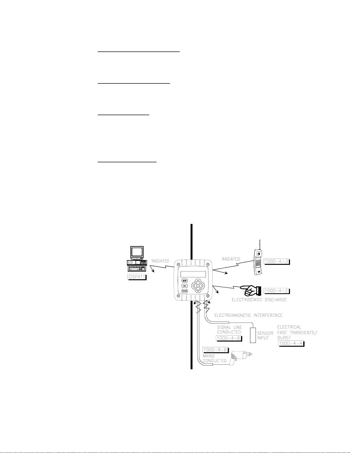
The transmitter is designed to provide protection from most normally encountered
electromagnetic interference. This protection exceeds U.S. standards and meets European IEC
1000 (EN 61000) series testing for electromagnetic and radio frequency emissions and
immunity. Refer to Figure 1-1 and the specifications in Section 2.1 for more information.
Figure 1-1 EMC Diagram
aluesalues
alues
aluesalues
EMISSIONS
IMMUNITY
Page 6

PAGE 6
Section 2 - SpecificationsSection 2 - Specifications
Section 2 - Specifications
Section 2 - SpecificationsSection 2 - Specifications
2.1 Operational2.1 Operational
2.1 Operational
2.1 Operational2.1 Operational
Display Two-line by 16 character LCD
NOTE: The measured value (conductivity, % concentration or TDS) and temperature can be
displayed separately or shown together on a single screen. The corresponding 4-20
mA analog output value can also be shown. (When measuring concentration, the
transmitter can also show a corresponding readout of uncompensated conductivity.)
Measurement Ranges
Conductivity µS/cm: 0-200.0 or 0-2000
mS/cm: 0-2.000, 0-20.00, 0-200.0 or 0-2000
S/cm: 0-2.000
% Concentration 0-99.99% or 0-200.0%
TDS 0-9999 ppm
Temperature -4.0 to 347.0°F or -20.0 to +175.0°C
Analog Output 4.00-20.00 mA
Ambient Conditions:
Operation -4 to +140°F (-20 to +60°C); 0-95% relative humidity, non-
condensing
Storage -22 to +158°F (-30 to +70°C); 0-95% relative humidity, non-
condensing
Temperature Compensation Automatic from 14.0 to 347.0°F (-10.0 to +175.0°C) with
selection for Pt 1000 ohm RTD temperature element, or
manually fixed at a user-set temperature
NOTE: The selected measurement (conductivity, % conc. or TDS) determines which of the
following temperature compensation methods are available:
Linear % per °C slope, built-in natural water temperature properties table, userentered temperature table, or no compensation
Sensor-to-Transmitter Distance Maximum cable length is a function of the measuring range
and allowable non-linearity. The following schedule is
recommended:
Full-scale Range Max. Length
200 to 2000 µS/cm 200 ft. (61 m)
2000 to 2,000,000 µS/cm 300 ft. (91 m)
NOTE: When measuring % concentration, convert the transmitter full-scale value to
conductivity to determine the maximum distance.
Page 7

Power Requirements (Class 2 Power Supply):
Two-wire Hookup 16-30 VDC
Three-wire Hookup 14-30 VDC
Four-wire Hookup 12-30 VDC
Calibration Methods:
Sensor Zero With the dry sensor in air, press keys to initiate
(all measurements) automatic system zeroing
Conductivity Measurement:
COND CAL Enter compensation reference temperature, and reference
solution’s known linear % per °C slope and value
SAMPLE CAL Enter one sample value (determined by laboratory analysis
or a comparison reading)
ELECTRONIC CAL This method requires that the sensor be removed from the
process and utilizes a decade resistance box to simulate
conductivity rather than an actual solution.
Concentration Measurement:
CONC CAL Enter one sample value (determined by laboratory analysis
or a comparison reading)
PAGE 7
COND CAL Enter compensation reference temperature, and reference
solution’s known linear % per °C slope and value
TDS Measurement:
TDS CAL Enter one sample value (determined by laboratory analysis
or a comparison reading)
Analog Output Isolated 4-20 mA output with 0.004 mA (12-bit) resolution
NOTE: The output can be assigned to represent the measured value (conductivity, %
concentration or TDS) or measured temperature. Parameter values can be entered to
define the endpoints at which the 4 mA and 20 mA output values are desired (range
expand). During calibration, the output is automatically held at the last measured
value and, upon completion, returned to its active state.
Maximum Loop Load Dependent on power supply voltage, transmitter hookup
arrangement, and wire resistance (see load resistance
charts for respective hookup diagrams in Section 4.2, 4.3 or
4 .4)
Memory (non-volatile) All user settings are retained indefinitely without battery
backup
Electrical Certifications UL, C-UL Pending
Page 8

PAGE 8
2.2 T2.2 T
ransmitter Pransmitter P
2.2 T
ransmitter P
2.2 T2.2 T
ransmitter Pransmitter P
Accuracy* ± 0.1% of span
Sensitivity* ± 0.05% of span
Repeatability* ± 0.05% of span
Temperature Drift* Zero and Span: ± 0.02% of span per °C
Response Time 1-60 seconds to 90% of value upon step change (with
*These typical performance specifications are:
1. Based on 25°C with conductivity of 500 µS/cm and higher. Consult factory for applications in
2. Derated above 100°C to the maximum displayed temperature of 200°C. Consult factory for details.
2.3 Mechanical2.3 Mechanical
2.3 Mechanical
2.3 Mechanical2.3 Mechanical
Enclosure Polycarbonate; NEMA 4X general purpose; choice of
Mounting Configurations Panel, wall, pipe or integral sensor mounting
Dimensions With Back Cover:
which conductivities are less than 500 µS/cm.
erformance (Electrical, Analog Outputs)erformance (Electrical, Analog Outputs)
erformance (Electrical, Analog Outputs)
erformance (Electrical, Analog Outputs)erformance (Electrical, Analog Outputs)
sensor filter setting of zero)
included mounting hardware
3.75 in. W x 3.75 in. H x 2.32 in. D
(95 mm W x 95 mm H x 60 mm D)
Without Back Cover for Panel Mount:
3.75 in. W x 3.75 in. H x 0.75 in. D
(95 mm W x 95 mm H x 19 mm D)
Net Weight 10 oz. (280 g) approximately
Page 9

PAGE 9
Section 3 - Physical InstallationSection 3 - Physical Installation
Section 3 - Physical Installation
Section 3 - Physical InstallationSection 3 - Physical Installation
Unpack and examine the equipment even if you do not use it immediately. If there is evidence of
damage, notify the transit carrier immediately.
Recommendation: Save the shipping carton and packing materials in case the instrument must
be stored or re-shipped.
3.1 Location3.1 Location
3.1 Location
3.1 Location3.1 Location
1. It is recommended to locate the transmitter as close as possible to the installed sensor.
The maximum allowable distance between an installed sensor and the transmitter
depends upon the full-scale value you set for the transmitter measuring range:
200-2000 µS/cm
Full-scale Value
200 feet (61 m) max. 300 feet (91 m) max.
NOTE: When measuring % concentration, convert the transmitter full-scale value to
conductivity to determine the maximum distance.
2. Mount the transmitter in a location that is:
• Clean and dry where there is little or no vibration.
• Protected from corrosive fluids.
• Within ambient temperature limits (-4 to +140°F or -20 to +60°C).
CAUTION:
EXPOSING THE TRANSMITTER TO DIRECT SUNLIGHT MAY INCREASE
THE OPERATING TEMPERATURE ABOVE ITS SPECIFIED LIMIT, AND
DECREASE DISPLAY VISIBILITY.
2000-2,000,000 µS/cm
Full-scale Value
Page 10
PAGE 10
3.2 P3.2 P
anel Mounting (DA201A)anel Mounting (DA201A)
3.2 P
anel Mounting (DA201A)
3.2 P3.2 P
anel Mounting (DA201A)anel Mounting (DA201A)
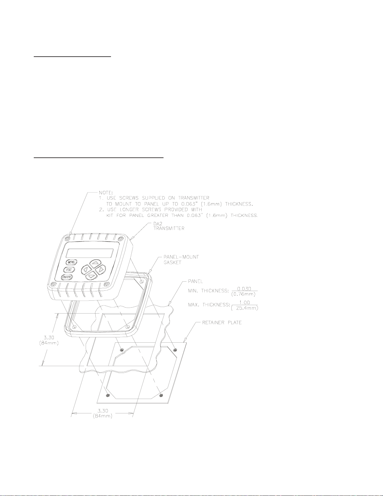
Figure 3-1 illustrates how to panel mount the transmitter using the supplied panel mount
hardware kit.
1. Cut a 3.30-inch (84 mm) square cutout hole in panel.
2. Position panel-mount gasket over cutout in front of panel, and place retainer plate
behind panel with its four threaded inserts facing away from back of panel.
3. Attach transmitter to retainer plate using its four captive screws.
NOTE: If panel is too thick, remove captive screws from transmitter, and use longer screws
provided in hardware kit.
FIGURE 3-1 Panel Mounting Details (DA201A)
Page 11
PAGE 11
3.3 W3.3 W
all and Pipe Mounting (DA202A)all and Pipe Mounting (DA202A)
3.3 W
all and Pipe Mounting (DA202A)
3.3 W3.3 W
all and Pipe Mounting (DA202A)all and Pipe Mounting (DA202A)
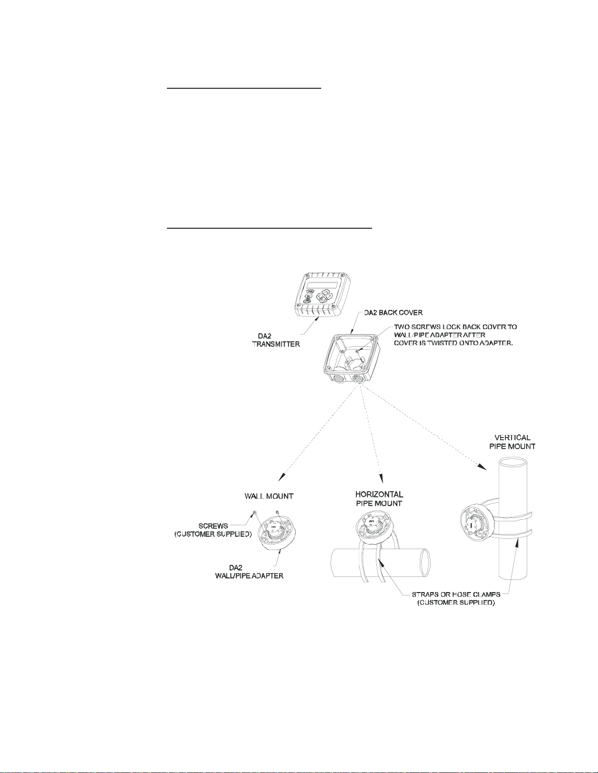
Figure 3-2 illustrates how to wall or pipe mount the transmitter using the supplied hardware kit.
Determine the mounting method, and attach the hardware as shown.
1. Fasten the wall/pipe adapter to the wall or pipe.
2. Using a blunt tool, open both cable entry knockout holes in the back cover.
3. Insert-and-twist the back cover onto the installed wall/pipe adapter, and tighten its two
screws to lock back cover onto the adapter.
4. Attach transmitter to back cover using its four captive screws.
FIGURE 3-2 Wall and Pipe Mounting (DA202A)
Page 12
PAGE 12
3.4 Integral Sensor Mounting (DA202A with HC1012000 only)3.4 Integral Sensor Mounting (DA202A with HC1012000 only)
3.4 Integral Sensor Mounting (DA202A with HC1012000 only)
3.4 Integral Sensor Mounting (DA202A with HC1012000 only)3.4 Integral Sensor Mounting (DA202A with HC1012000 only)
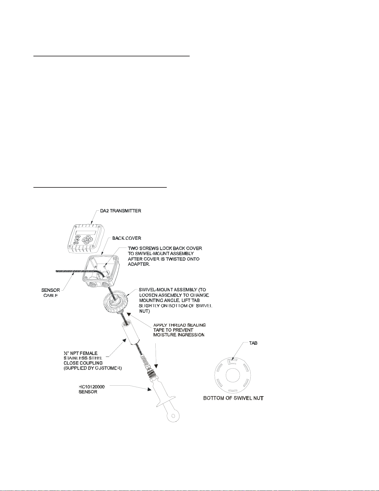
Figure 3-3 illustrates how to integrally mount the transmitter onto a sensor using the supplied
mounting hardware kit.
1. Using a blunt tool, open knockout hole in bottom of swivel ball for routing the sensor
cable.
2. Attach swivel-mount assembly onto back end of sensor using a stainless steel 1/2”
NPT female close coupling that you provide. Be sure to tape the NPT threads to
prevent moisure ingression
3. Insert-and-twist the back cover onto the installed swivel-mount assembly. Tighten its
two screws to lock the back cover onto the swivel-mount assembly.
NOTE: To change mounting angle, loosen swivel-mount assembly by lifting tab on bottom of
swivel nut. Position to desired angle and re-tighten swivel nut.
4. Attach transmitter to back cover using its four captive screws.
FIGURE 3-3 Integral Sensor Mounting (DA202A)
Page 13
PAGE 13
Section 4 - Electrical ConnectionsSection 4 - Electrical Connections
Section 4 - Electrical Connections
Section 4 - Electrical ConnectionsSection 4 - Electrical Connections
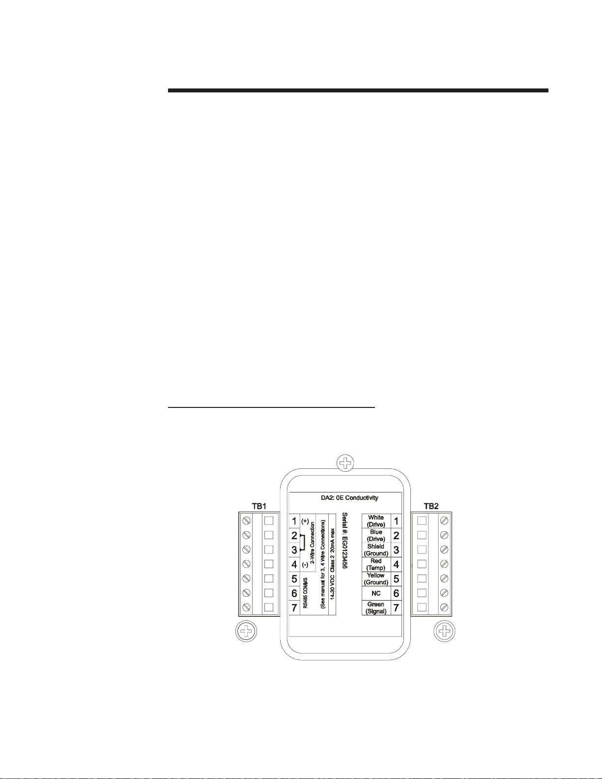
Figure 4-1 shows the terminal block arrangement and terminal designations for the transmitter.
NOTE: All terminals are suitable for single wires up to 14 AWG (2.5 mm2).
Wiring Tip! To comply with European Community (CE) electromagnetic
compatibility requirements, follow these general wiring guidelines:
1. Locate transmitter as far as possible from motors and other non-CE certified devices
with excessive electromagnetic emissions.
2. Use specified ferrites and cables. Failure to do so may eliminate compliance. Locate all
ferrites as close as possible to the transmitter.
• DC Power Supply Cable: Connect cable shield to earth ground at the supply end. Loop
cable 2-1/2 times through ferrite (Steward #28B0686-200, Fair-Rite Corp. #2643665702
or equivalent).
• Sensor Cable: Keep cable shields as short as possible. At the transmitter end, connect
the outer shield to earth ground, and the inner shield to the SHIELD terminal. Clamp
ferrite (Steward #28A2025-OAO, Fair-Rite Corp. #0431164281, or equiv-alent) on
sensor cable.
• Analog mA Output Cable (four-wire hookup only): Connect cable shield to earth ground
at the supply end. Loop cable 2-1/2 times through ferrite (Steward #28B0686-200, FairRite Corp. #2643665702, or equivalent).
FIGURE 4-1 Transmitter Terminal Designations
Page 14
PAGE 14
1 White (Drive)
2 Blue (Drive)
3 Shield (Ground)
4 Red (Temp)
5 Yellow (Ground)
6
7
Green (Signal)
Green
Yellow
Inner Shield
White
Blue
Red
Outer Shield
To Earth Ground
4.1 HC1 Series Electrodeless Conductivity Sensor Wiring
Depending on how transmitter is mounted, route the sensor (or interconnect) cable into the
transmitter as follows:
• Wall/Pipe-mounted Transmitter: Route cable through left side cable entry knockout hole
in the back cover.
• Panel-mounted Transmitter: Route cable behind panel to the exposed TB2 terminal
strip.
• Integral Sensor-mounted Transmitter: Route cable through a 1/2” NPT female close
coupler and then through the swivel ball knockout hole and center hole in back cover.
(Do not open left side cable entry knockout hole in back cover.)
Wiring Tip! Route the sensor cable in 1/2-inch, grounded metal conduit to
protect it from moisture, electrical noise, and mechanical damage.
For installations where the distance between sensor and transmitter exceeds
the sensor cable length, indirectly connect the sensor to the transmitter using a
junction box and interconnect cable.
NOTE: Do not route the sensor cable in any conduit containing AC or DC power wiring
(“electrical noise” may interfere with the sensor signal). Also, always re-calibrate the
system when the cable length between sensor and transmitter changes.
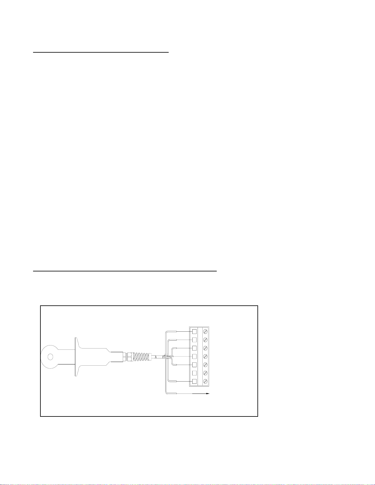
Refer to Figure 4-2 and connect the sensor (or interconnect) cable wires as shown, matching
colors as indicated. (Terminal 6 is unused.)
NOTE: For systems not requiring CE compliance and lacking an earth ground, connect the
outer shield to Terminal 3 on TB2.
FIGURE 4-2 Connecting HC1 Series Electrodless Conductivity Sensor
Page 15
PAGE 15
4.2 T4.2 T
wowo
--
4.2 T
4.2 T4.2 T
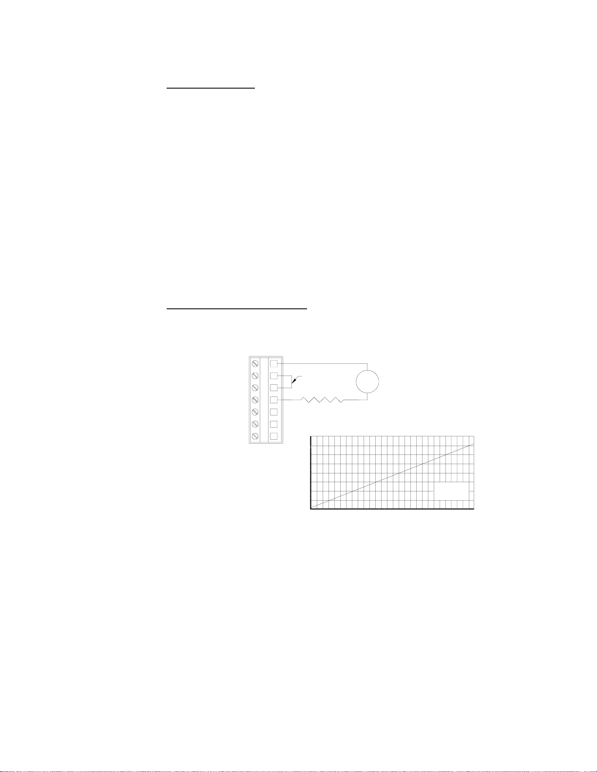
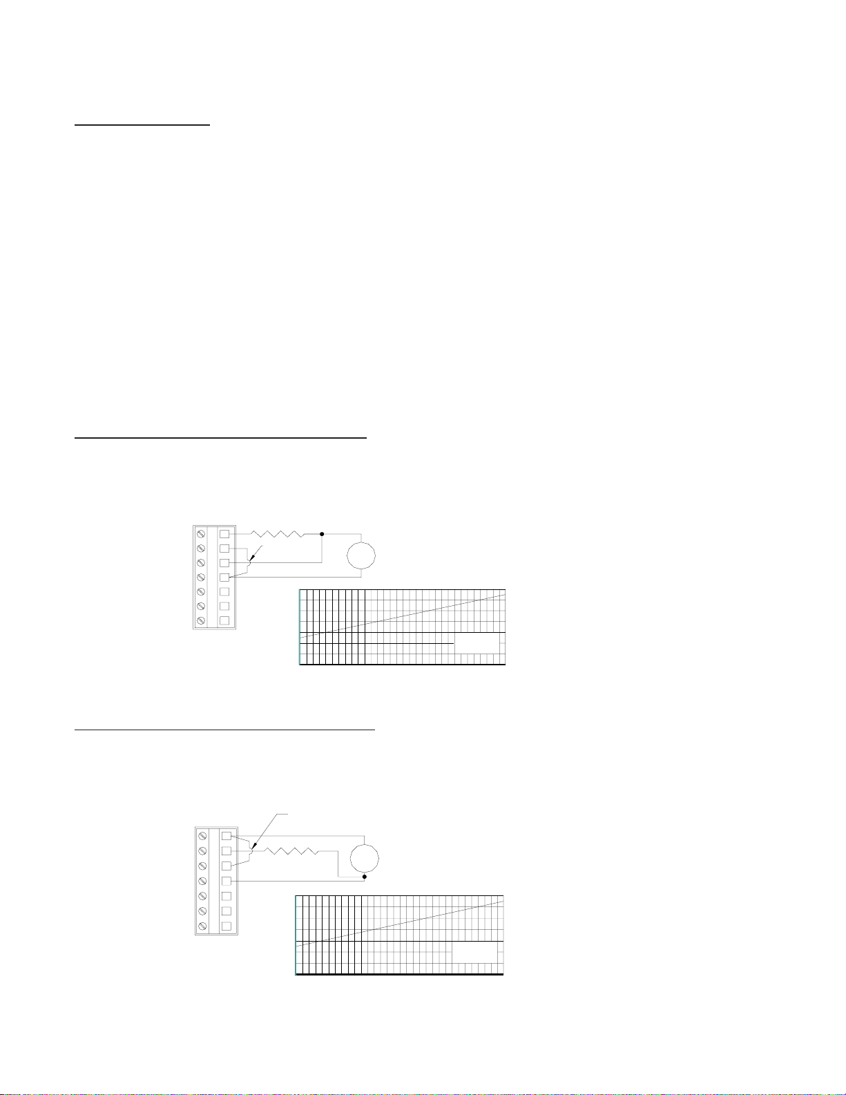
In a two-wire hookup, at least 16 VDC is required for operation. A load device can be connected
in the current loop (see Figure 4-3 for details).
Depending on how the transmitter is mounted, route the DC power/analog output wiring into the
transmitter as follows:
• Wall/Pipe-mounted Transmitter: Route cable through right side cable entry knockout
• Panel-mounted Transmitter: Route cable behind panel to the exposed TB1 terminal
• Integral Sensor-mounted Transmitter: Route cable through right side cable entry
FIGURE 4-3 Two-Wire Hookup
Wire HookupWire Hookup
wo
-
Wire Hookup
wowo
--
Wire HookupWire Hookup
hole in the back cover.
strip.
knockout hole in the back cover. (Do not open left side cable entry knockout hole in
cover).
Wiring Tip! Use high quality, shielded instrumentation cable.
1
2
3
Jumper
Required
4
5
6
7
Loop Resistance
(See nomograph)
800
700
600
500
400
300
200
RESISTANCE
IN OHMS
100
0
16
18 20 22 24 26 28
+
Loop Power
16-30VDC
Class 2
-
DC VOLTAGE
LOOP LOAD
50 Ohms/Volt
30
Page 16
PAGE 16
4.3 Three4.3 Three
4.3 Three
4.3 Three4.3 Three
--
Wire HookupWire Hookup
-
Wire Hookup
--
Wire HookupWire Hookup
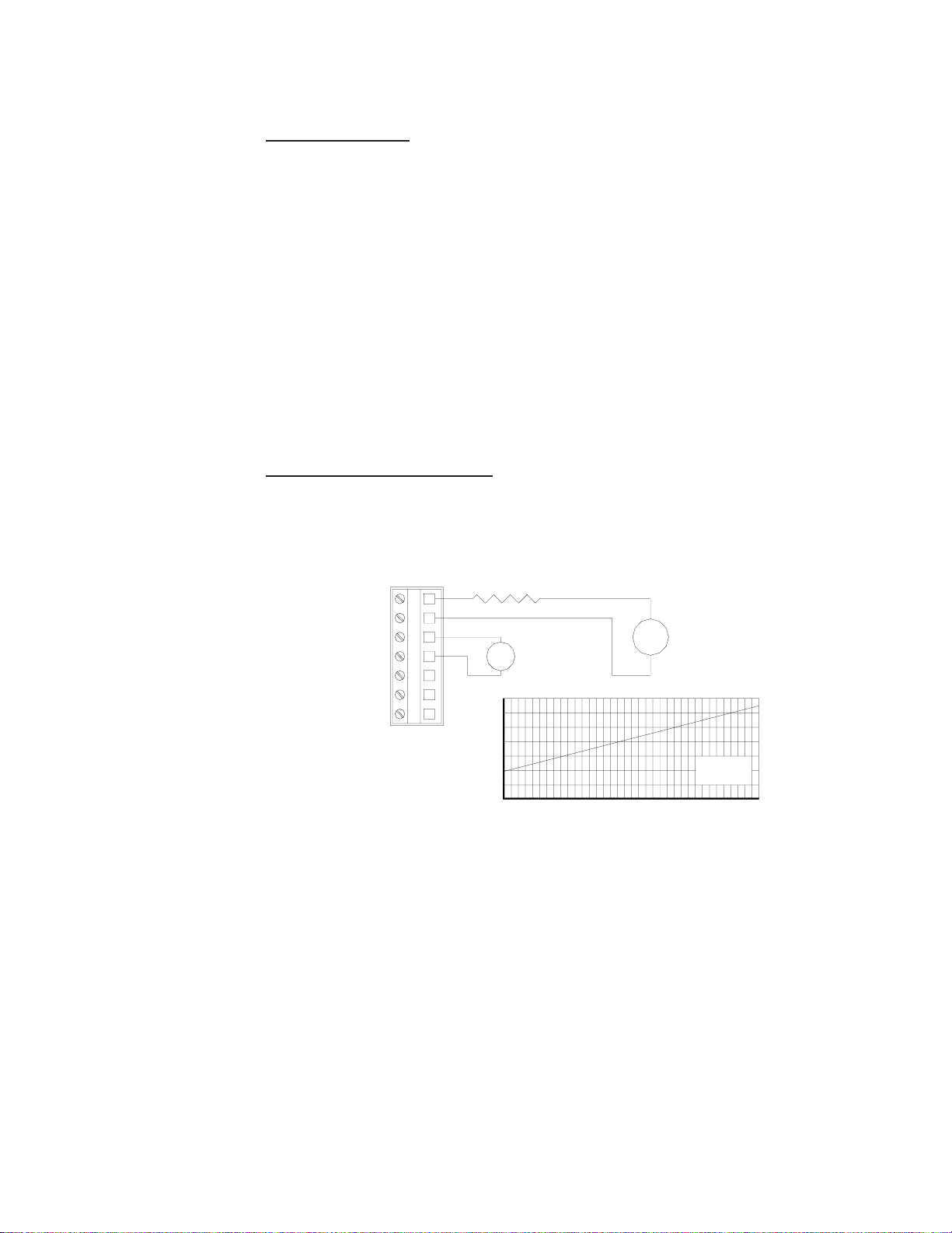
In a three-wire hookup, the transmitter can be wired two ways depending on load “sinking” or
“sourcing”. At least 14 VDC is required for operation.
Depending on how the transmitter is mounted, route the DC power, analog output, and wiring
into the transmitter as follows:
• Wall/Pipe-mounted Transmitter: Route cable through right side cable entry knockout
hole in the back cover.
• Panel-mounted Transmitter: Route cable behind panel to the exposed TB1 terminal
strip.
• Integral Sensor-mounted Transmitter: Route cable through right side cable entry
knockout hole in the back cover. (Do not open left side cable entry knockout hole in
cover).
Wiring Tip! Use high quality, shielded instrumentation cable.
FIGURE 4-4 Three-Wire Hookup - Load Sinking
Loop Resistance
(See nomograph)
1
2
3
4
5
6
7
Jumper
Required
1400
1200
1000
800
600
400
RESISTANCE
IN OHMS
200
0
14 16 18
+
Loop Power
14-30VDC
Class 2
-
LOOP LOAD
50 Ohms/Volt
20 22 24 26 28 30
DC VOLTAGE
FIGURE 4-5 Three-Wire Hookup - Load Sourcing
Jumper Required
1
2
3
4
5
6
7
Loop Resistance
(See nomograph)
1400
1200
1000
800
600
IN OHMS
400
RESISTANCE
200
0
14 16 18
+
Loop Power
14-30VDC
Class 2
-
LOOP LOAD
50 Ohms/Volt
20 22 24 26 28 30
DC VOLTAGE
Page 17
PAGE 17
4.4 Four4.4 Four
4.4 Four
4.4 Four4.4 Four
--
Wire HookupWire Hookup
-
Wire Hookup
--
Wire HookupWire Hookup
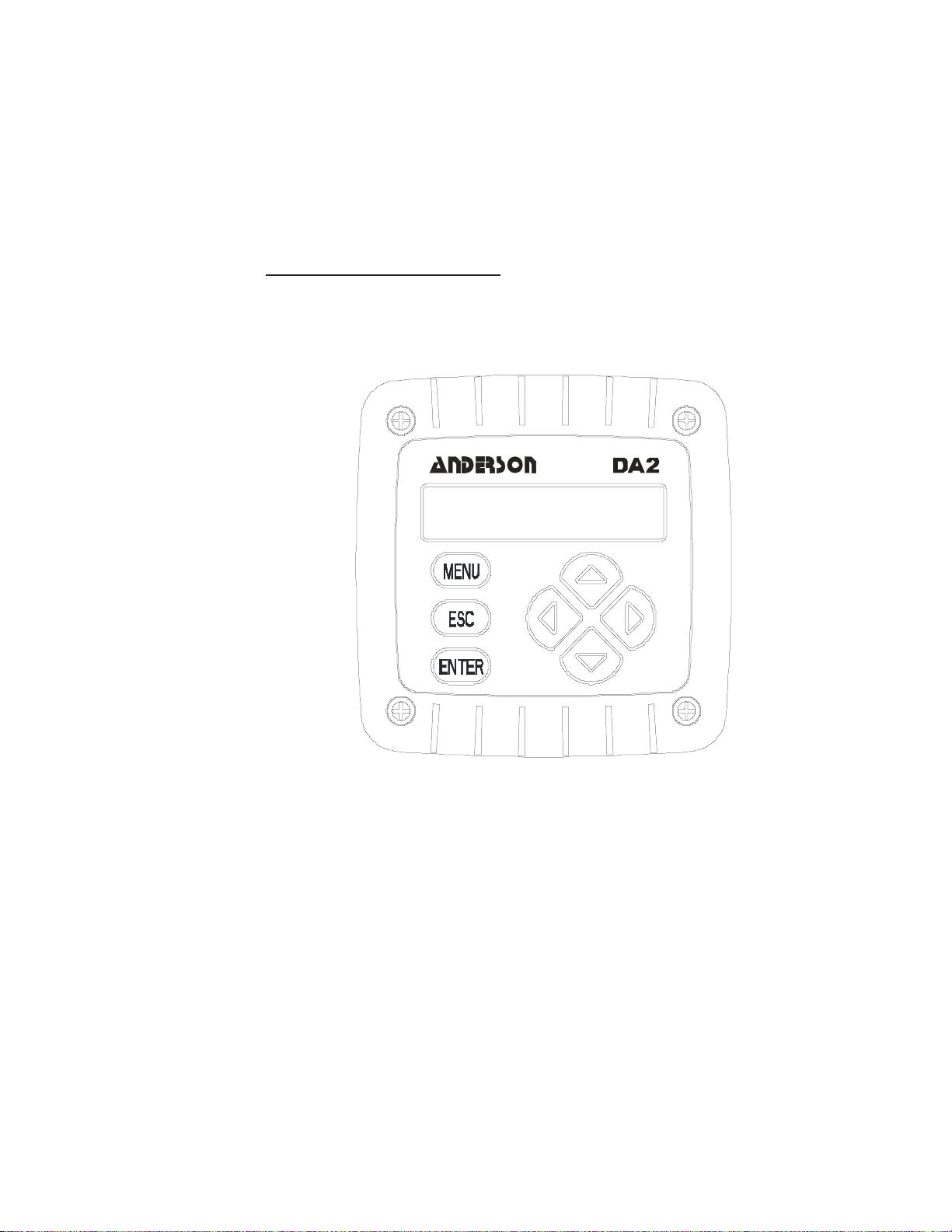
In a four-wire hookup, at least 12 VDC is required for operation.
Depending on how the transmitter is mounted, route the DC power, analog output wiring into the
transmitter as follows:
• Wall/Pipe-mounted Transmitter: Route cable through right side cable entry knockout
hole in the back cover.
• Panel-mounted Transmitter: Route cable behind panel to the exposed TB1 terminal
strip.
• Integral Sensor-mounted Transmitter: Route cable through right side cable entry
knockout hole in the back cover. (Do not open left side cable entry knockout hole in
cover).
Wiring Tip! Use high quality, shielded instrumentation cable
FIGURE 4-6 Four-Wire Hookup
Loop Resistance
(See nomograph)
1
2
3
4
5
6
7
+
External Power
12-30VDC
-
Class 2
1400
1200
1000
800
600
400
RESISTANCE
IN OHMS
200
0
161412
DC VOLTAGE
+
Loop Power
12-30VDC
Class 2
-
LOOP LOAD
50 Ohms/Volt
2624222018
3028
Page 18

PAGE 18
Section 5 - OperationSection 5 - Operation
Section 5 - Operation
Section 5 - OperationSection 5 - Operation
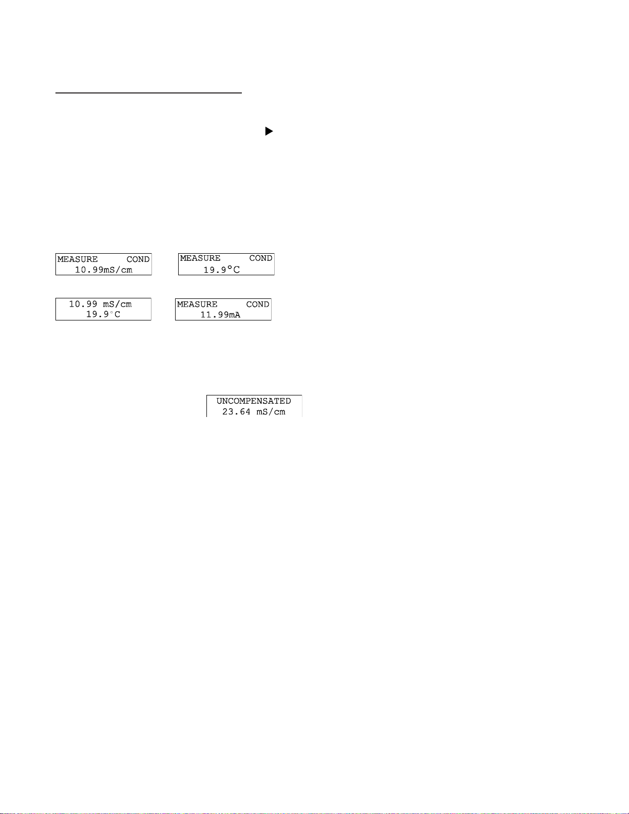
The user interface consists of a two-line LCD display and a keypad with MENU, ENTER, ESC,
ÕÕ
ÖÖ
Ö,
ÖÖ
××
×, and
××
Õ,
ÕÕ
5.1 Display5.1 Display
5.1 Display
5.1 Display5.1 Display
By using the keypad, you can display three types of screens:
1. Measure Screens: The normal display mode shows the measured value (conductivity,
2. MENU Screens: These top-level and lower-level (submenu) screens within the three
ØØ
Ø keys.
ØØ
ÖÖ
% concentration or TDS). Pressing the
measurement readouts:
• Measured process temperature
• Measured value and temperature
• Measured analog output mA value
• Uncompensated conductivity corresponding to % concentration readout (only
shown when transmitter is set to measure concentration)
main branches of the menu tree are used to access edit/selection screens for configuration. (EXIT screens at the end of each menu branch enable you to move up one level
in the menu tree by pressing the ENTER key. This is functionally the same as pressing
the ESC key.)
Ö key sequentially scrolls through these other
ÖÖ
3. Edit/Selection Screens: These screens enter values / choices to calibrate, configure,
and test the transmitter.
5.2 K5.2 K
eypadeypad
5.2 K
eypad
5.2 K5.2 K
eypadeypad
The keypad enables you to move throughout the transmitter menu tree. The keys and their
related functions are:
1. MENU key: Pressing this key with the MEASURE screen displayed shows the “MAIN
MENU CALIBRATE” screen. To display the configure or test/maint top-level main
ØØ
branch screen, press the
played always shows the top-level screen in that branch. (Pressing the MENU key also
“aborts” the procedure to change values or selections.)
2. ENTER key: Pressing this key does two things; it displays submenu and edit/selection
screens, and it enters (saves) configuration values/selections.
3. ESC key: Pressing this key always takes the display up one level in the menu tree.
(Example: With any “MAIN MENU” screen displayed, pressing the ESC key once takes
the display up one level to the measure screen.) The ESC key can also “abort” the
procedure to change a value or selection.
4.
ÕÕ
Õ and
ÕÕ
following:
• MEASURE Screen: Changes readout (in continuous loop sequence) to show
• Menu Screens: These keys are non-functional.
ÖÖ
Ö keys: Depending on the type of displayed screen, these keys do the
ÖÖ
different measurements.
Ø key. Pressing the MENU key with a menu screen dis-
ØØ
• Edit/Selection Screens: Moves cursor left or right to select digit for adjustment with
××
× and
××
5.
××
× and
××
following:
ØØ
Ø keys.
ØØ
ØØ
Ø keys: Depending on the type of displayed screen, these keys do the
ØØ
Page 19
• MEASURE Screen: These keys are non-functional.
• Menu Screens: Moves up or down respectively between other same-level menu
screens.
• Edit/Selection Screens: Adjusts selected digit value up or down, or moves up or
down between choices.
FIGURE 5-1 Transmitter Keypad
PAGE 19
Page 20
PAGE 20
5.3 MEASURE Screen (normal display mode)5.3 MEASURE Screen (normal display mode)
5.3 MEASURE Screen (normal display mode)
5.3 MEASURE Screen (normal display mode)5.3 MEASURE Screen (normal display mode)
The MEASURE screen is normally displayed. Pressing the MENU key temporarily replaces the
MEASURE screen with the top-level “MAIN MENU
Using the keypad, you can then display other screens to calibrate, configure or test the
transmitter. If the keypad is not used within 30 minutes, except during calibration or while
using specific transmitter test/ maintenance functions, the display will automatically
return to the MEASURE screen. To display the measure screen at any time, press the MENU
key once and then press the ESC key once.
The MEASURE screen can show four different readout versions. To select between them, in
ÕÕ
ÖÖ
Õ or
continuous loop sequence, press the
versions:
Ö key. These are examples of the different
ÕÕ
ÖÖ
CALIBRATE” branch selection screen.
ÖÖ
Ö
ÖÖ
ÖÖ
Ö
ÖÖ
When set to measure concentration, the transmitter can also show an uncompensated
conductivity reading corresponding to the measured concentration, as illustrated by this
example:
NOTE: When the transmitter returns to its normal MEASURE screen mode, the appearing
readout is always the version last selected.
Note that three MEASURE screen readout examples show the factory-default “cond”
notation on their top lines, illustrating the transmitter notation feature. To create your
own notation, refer to Section 7.2, subheading “ENTER NOTE (top line of MEASURE
screen).”
When the measured value is beyond the transmitter measuring range, a series of “ + “ or “ - “
screen symbols appear, respectively indicating that the value is above or below range.
ÖÖ
Ö
ÖÖ
ÖÖ
Ö
ÖÖ
Page 21
PAGE 21
Section 6 - Menu StructureSection 6 - Menu Structure
Section 6 - Menu Structure
Section 6 - Menu StructureSection 6 - Menu Structure
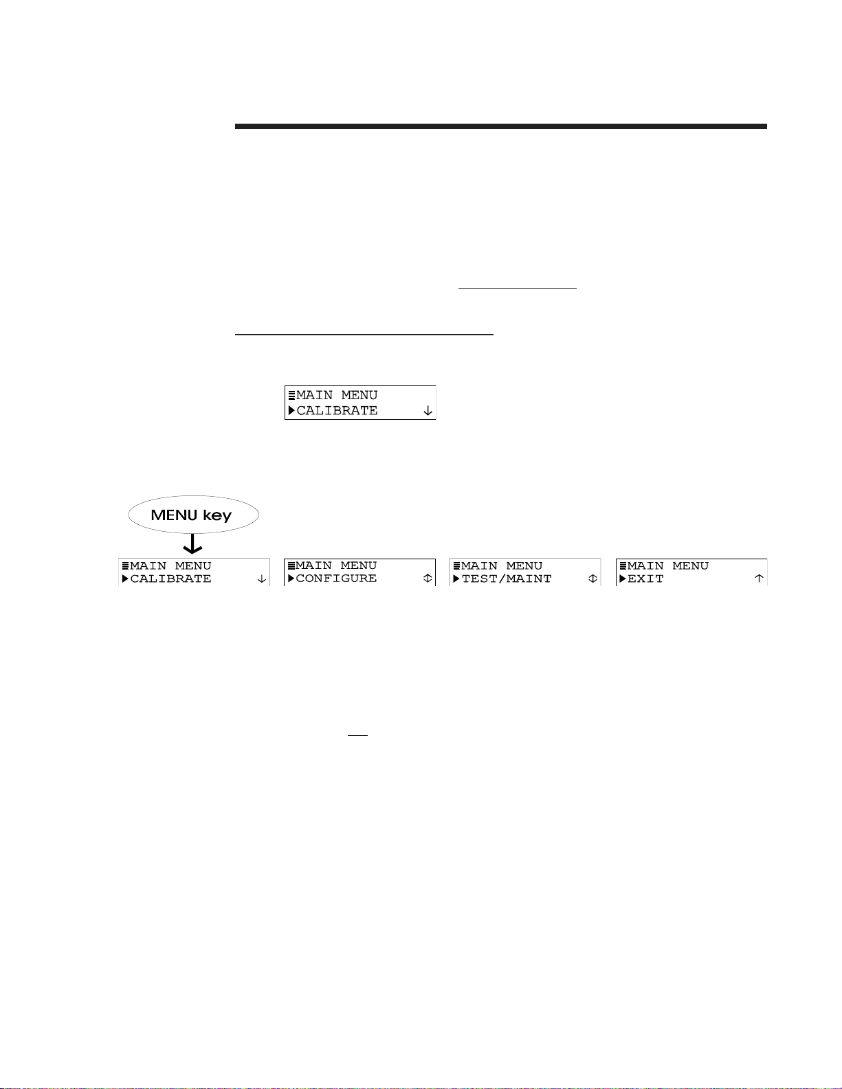
The transmitter menu tree is divided into three main branches: CALIBRATE, CONFIGURE, and
TEST/MAINT. Each main branch is structured similarly in layers with top-level screens, related
lower-level submenu screens and, in many cases, sub-submenu screens.
Each layer contains an EXIT screen to return the display up one level to the previous layer of
screens.
Menu Structure Tip! For operating convenience, the layers within each main
branch are organized with the
beginning, rather than the function screens used for initial startup.
6.1 Displaying Main Branch Selection Screens6.1 Displaying Main Branch Selection Screens
6.1 Displaying Main Branch Selection Screens
6.1 Displaying Main Branch Selection Screens6.1 Displaying Main Branch Selection Screens
1. With the MEASURE screen displayed, pressing the MENU key always shows the
other type of screen displayed always returns the display to the top of that respective
menu branch).
most frequently used function screens at their
branch selection screen. (Pressing the MENU key with any
2. Press
3. With the desired MAIN MENU branch selection screen displayed, press ENTER key to
ØØ
Ø and
ØØ
screens (CALIBRATE, CONFIGURE or TEST/MAINT), or the EXIT screen:
display the
××
× keys to select between the three MAIN MENU branch selection
××
first top-level menu screen within that branch.
Page 22
PAGE 22
Ð
Ð
Ð
6.2 Displaying T6.2 Displaying T
6.2 Displaying T
6.2 Displaying T6.2 Displaying T
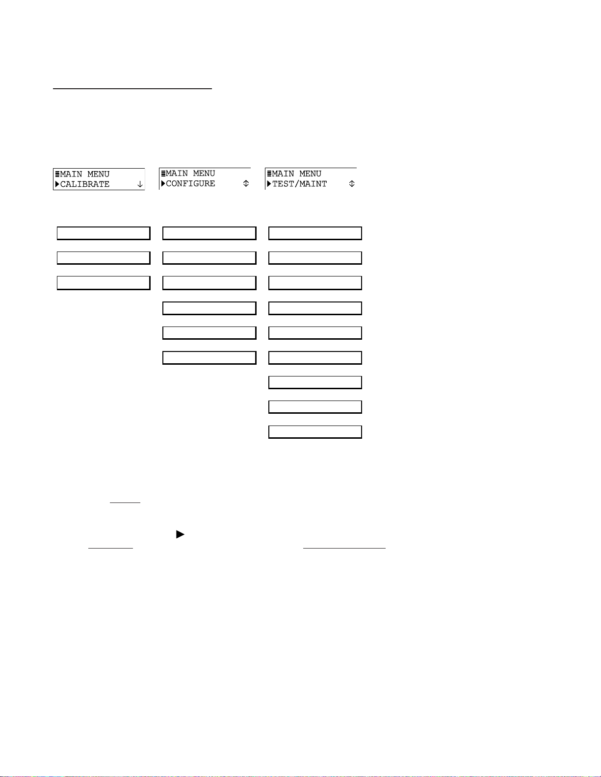
With the first top-level menu screen of the desired main branch displayed, use the
keys to scroll through other top-level screens to access a desired screen.
The top-level menu screens for each main branch are:
SENSOR SET OUTPUT STATUS
CAL OUTPUT SET PASSCODE HOLD OUTPUT
opop
-Level Menu Screens-Level Menu Screens
op
-Level Menu Screens
opop
-Level Menu Screens-Level Menu Screens
EXIT
LANGUAGE EPROM VERSION
SENSOR SELECT SIM
EXIT SIM SENSOR
RESET CONFIGURE
RESET CALIBRATE
EXIT
SET °C OR °F
OUTPUT
ØØ
Ø and
ØØ
××
×
××
Menu Structure Tip! A menu screen with a horizontal bar symbol ( | ) at the start
of its first line indicates there is a related submenu or edit/selection screen.
A menu screen with a
second line indicates that you can select other screens within the same layer by
pressing the
you can move up or down between screens by respectively pressing the
ØØ
Ø key. When a “Ç” symbol appears, it indicates you have reached the end of
ØØ
the screens in that layer. You can select previous screens using the
ØØ
Ø key. A “
ØØ
symbol at the start and a “È” symbol at the end of its
RR
R“ symbol at the end of the second line indicates that
RR
××
× or
××
××
× key.
××
Page 23
PAGE 23
6.3 Displaying Submenu Screens6.3 Displaying Submenu Screens
6.3 Displaying Submenu Screens
6.3 Displaying Submenu Screens6.3 Displaying Submenu Screens
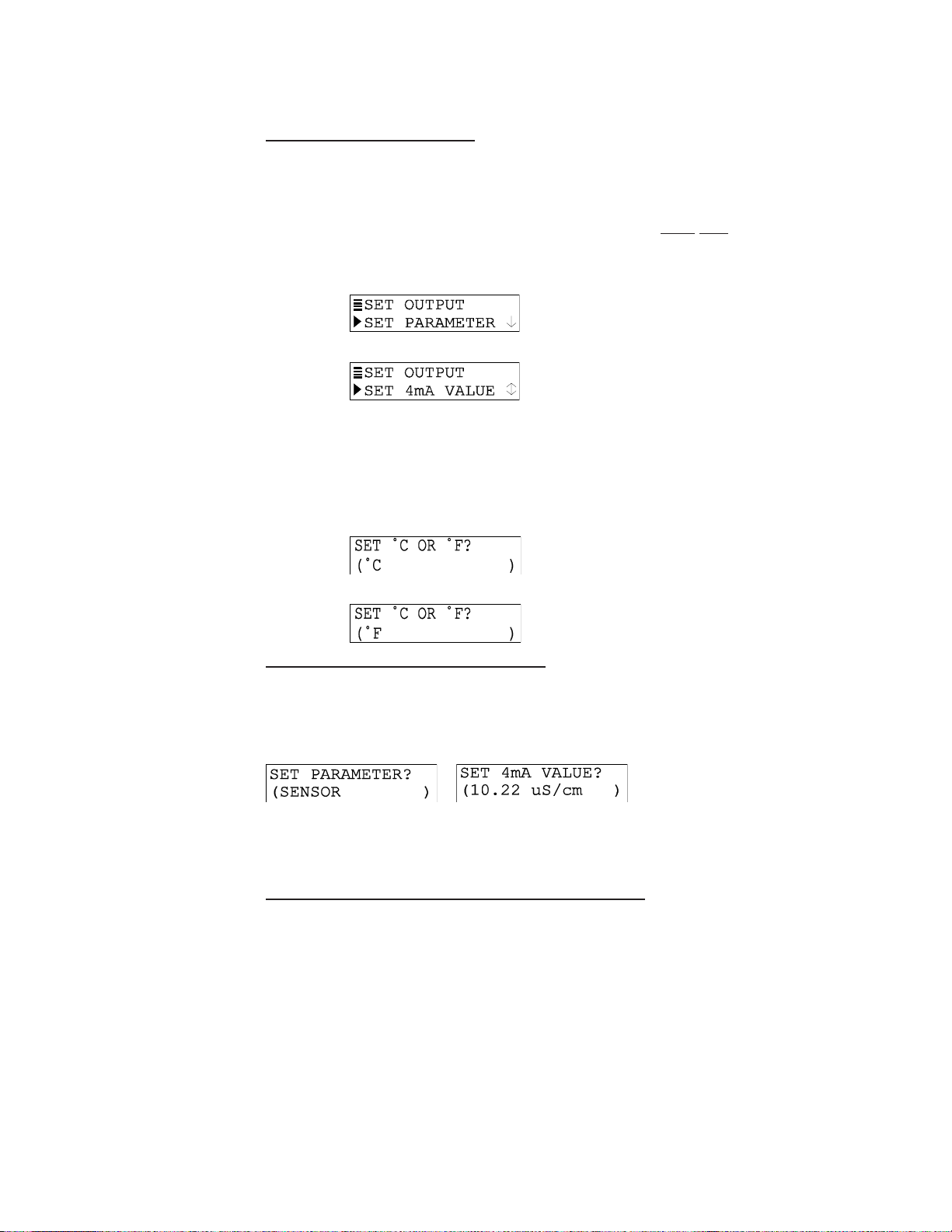
After selecting a top-level menu screen, press the ENTER key to display a related submenu or
edit/selection screen:
• Submenu Screens are usually linked to other related same-level screens. Pressing
ØØ
the
Ø key displays these other related submenu screens.
ØØ
Example: With this submenu screen displayed:
pressing the
• Edit/Selection Screens always have a first line ending with a “?”. Pressing the
ØØ
Ø key changes the value/ choice enclosed by parenthesis (second line on screen).
ØØ
Example: With this submenu screen displayed:
pressing the
6.4 Adjusting Edit / Selection Screen V6.4 Adjusting Edit / Selection Screen V
6.4 Adjusting Edit / Selection Screen V
6.4 Adjusting Edit / Selection Screen V6.4 Adjusting Edit / Selection Screen V
Use arrow keys to edit/change the value/choice enclosed by parenthesis (examples shown
above and below).
ØØ
Økey displays this related, same-level submenu screen:
ØØ
ØØ
Ø key displays this related choice:
ØØ
aluesalues
alues
aluesalues
××
× or
××
A choice can be changed by simply using the
adjusted using the
6.5 Entering (Storing) Edit/Selection Screen V6.5 Entering (Storing) Edit/Selection Screen V
6.5 Entering (Storing) Edit/Selection Screen V
6.5 Entering (Storing) Edit/Selection Screen V6.5 Entering (Storing) Edit/Selection Screen V
With the desired value/choice displayed, press the ENTER key to enter (store) it into the non-
volatile transmitter memory. The previous screen will then re-appear.
NOTE: You can always press the ESC key to abort saving a new setting. The original setting
will be retained.
ÕÕ
Õ and
ÕÕ
ÖÖ
Ö keys to select a digit, and
ÖÖ
××
× and
××
ØØ
Ø keys. Numerical values can be
ØØ
××
× and
××
alues/Choicesalues/Choices
alues/Choices
alues/Choicesalues/Choices
ØØ
Ø keys to adjust its value.
ØØ
Page 24
PAGE 24
Section 7 - TSection 7 - T
Section 7 - T
Section 7 - TSection 7 - T
NOTE: When the passcode feature is enabled (Section 7.5), you must successfully enter the
passcode before attempting to enter a configuration setting.
7.1 Selecting 7.1 Selecting
7.1 Selecting
7.1 Selecting 7.1 Selecting
The transmitter is normally equipped to display screens in English and Spanish (Español).
However, another language such as French (Français), German (Deutsche), etc. may be
substituted for Spanish. The transmitter is factory-set for English. To select the other language:
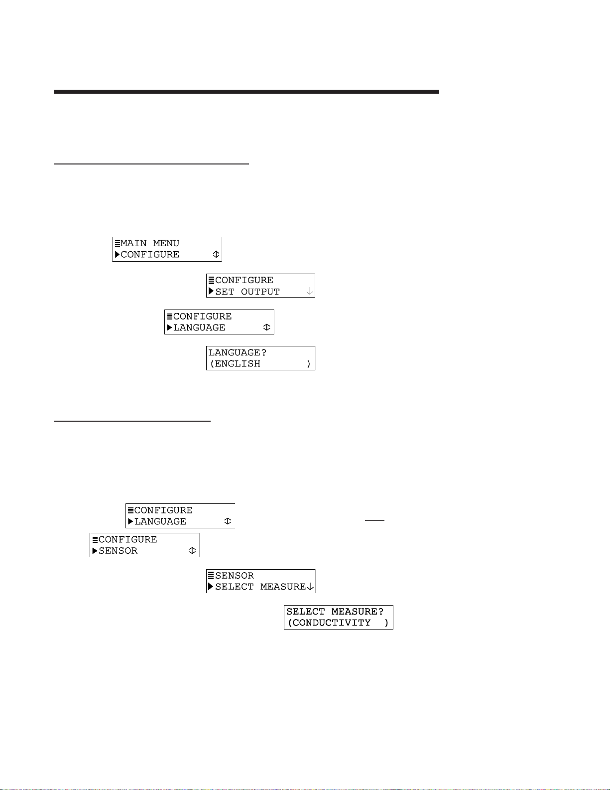
1. Press MENU key to display a “MAIN MENU” screen.
2. Press ENTER key to display
3. Press
4. Press ENTER key to display
LANGUAGELANGUAGE
LANGUAGE
LANGUAGELANGUAGE
If the
language, and press ENTER key to enter it.
ransmitter Configurationransmitter Configuration
ransmitter Configuration
ransmitter Configurationransmitter Configuration
to Operate T to Operate T
to Operate T
to Operate T to Operate T
ØØ
Ø key until screen appears.
ØØ
ransmitterransmitter
ransmitter
ransmitterransmitter
screen is not showing, use
.
. Use
ØØ
Ø or
ØØ
××
× key to display it.
××
ØØ
××
Ø or
× key to select a
ØØ
××
NOTE: After a language is selected and entered, all screens are displayed in that language.
7.2 Configuring Sensor Characteristics7.2 Configuring Sensor Characteristics
7.2 Configuring Sensor Characteristics
7.2 Configuring Sensor Characteristics7.2 Configuring Sensor Characteristics
The transmitter must be configured to define the characteristics of the sensor including its
temperature element type and “T” factor, and other related items such as selecting the
measurement and its format, temperature compensation, input signal filtering, etc.
SELECT MEASURE (conductivity, concentration or TDS)
1. With the screen displayed, press
.
2. Press ENTER key to display
3. Press ENTER key again to display a screen like . Use
××
and
× keys to select the desired measurement (conductivity, concentration or TDS),
××
and press ENTER key to enter it.
NOTE: If concentration was selected, measured conductivity must be converted to %
concentration by selecting a BUILT-IN chemical concentration table or creating a
USER-DEFINED table. See “CONFIG CONC” subheading for details.
ØØ
Ø key once to display
ØØ
.
ØØ
Ø
ØØ
Page 25
PAGE 25
WARNING:
CHANGING THE MEASUREMENT AUTOMATICALLY REPLACES ALL
USER-ENTERED CONFIGURATION VALUES WITH FACTORY-DEFAULTS.
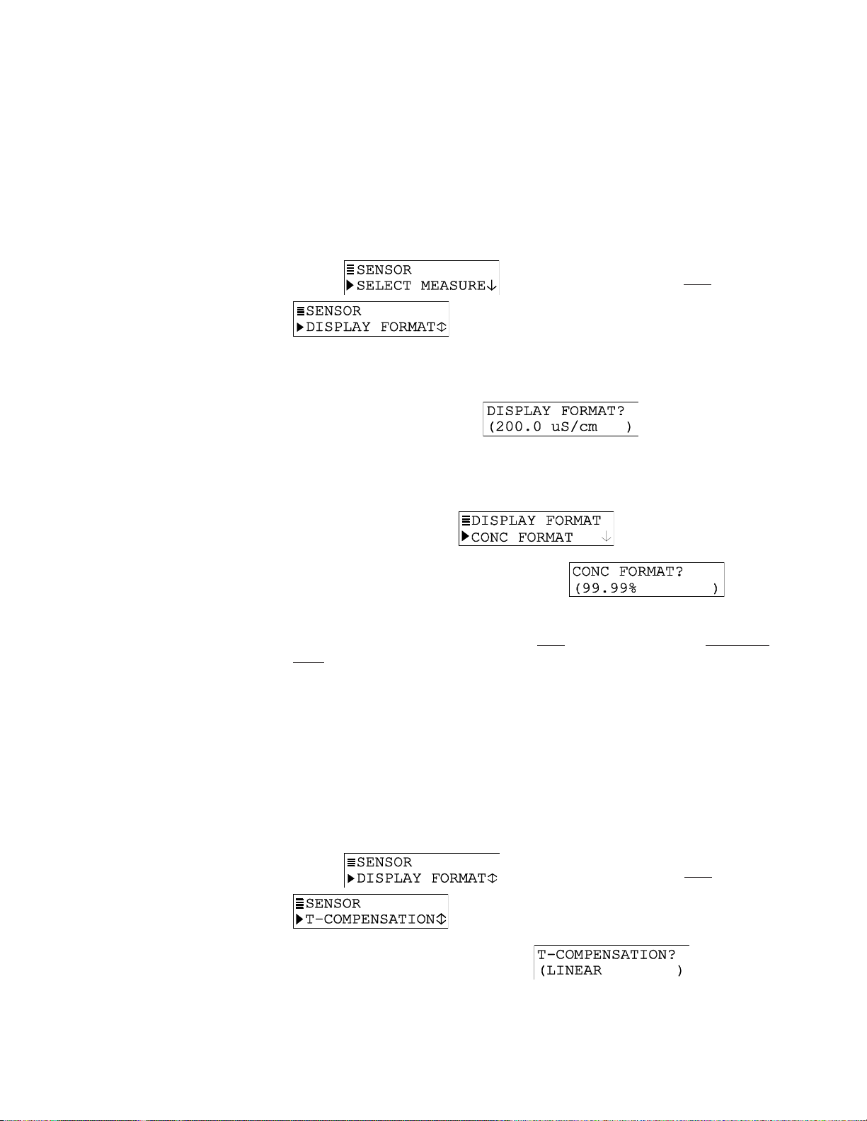
Select DISPLAY FORMAT
After choosing the measurement, select the desired display format for the MEASURE screen.
The selected units and resolution will also appear on all applicable edit/selection menu screens.
1. With the
.
2. Refer to the selected measurement category below and follow its steps:
Conductivity Display Format
Press ENTER key to display a screen like
select a format (2000 µS/cm, 200.0 µS/cm, 2.000 mS/cm, 20.00 mS/cm, 200.0 mS/cm, 2000
mS/cm, or 2.000 S/cm), and press ENTER key to enter it.
CONCENTRATION Display Format
1. Press ENTER key to display
2. Press ENTER key again to display a screen like
××
and
× keys to select a format (99.99% or 200.0%), and press ENTER key to enter it.
××
3. After the screen re-appears, press
sated conductivity MEASURE screen readout (and select conductivity range for USER-
DEFINED table, if used).
screen displayed, press
ØØ
Ø key once to display to format the uncompen-
ØØ
ØØ
Ø key once to display
ØØ
ØØ
. Use
Ø and
ØØ
.
××
× keys to
××
. Use
ØØ
Ø
ØØ
ØØ
××
Øand
4. Press ENTER key to display a screen like . Use
(same choices previously described for conductivity), and press ENTER key to enter it.
TDS Display Format
Display format configuration for TDS is always 0-9999 ppm. Consequently, there is no display
format screen.
Select Temperature COMPENSATION
Configure the required type of temperature compensation for the selected measurement.
1. With the
.
2. Press ENTER key to display a screen like
keys to select the type of compensation, and press ENTER key to enter it:
screen displayed, press
× keys to select a format
ØØ
××
ØØ
Ø key once to display
ØØ
. Use
ØØ
Ø and
ØØ
××
×
××
Page 26
PAGE 26
• LINEAR: Recommended for most aqueous solutions
• NATURAL WATER (not available for TDS measurement): Built-in temperature
properties table only for special applications — consult factory)
•TEMP TABLE: User-defined temperature table
• NONE: Measurement values are not compensated
NOTE: LINEAR is the factory default for temperature compensation with a 2.00% per °C
slope and 25.0°C reference temperature. This provides the best results for most
aqueous solutions. To enter different slope and reference temperature values for an
uncommon solution, refer to subheading “CONFIG LINEAR or CONFIG T-TABLE
Temperature Compensation” for details.
CONFIG CONC or CONFIG TDS Measurement (configuration not needed for conductivity)
Only when CONCENTRATION or TDS is selected must the transmitter be further
configured. If CONDUCTIVITY was selected, disregard this subsection — no measurement
configuration is needed.
CONCENTRATION Measurement Setup
Configure the transmitter with an appropriate table to convert measured conductivity into
displayed % concentration. If one of the transmitter’s BUILT-IN chemical concentration tables
matches the solution being measured, simply select that table. If not, you must create a USERDEFINED concentration table for the solution being measured.
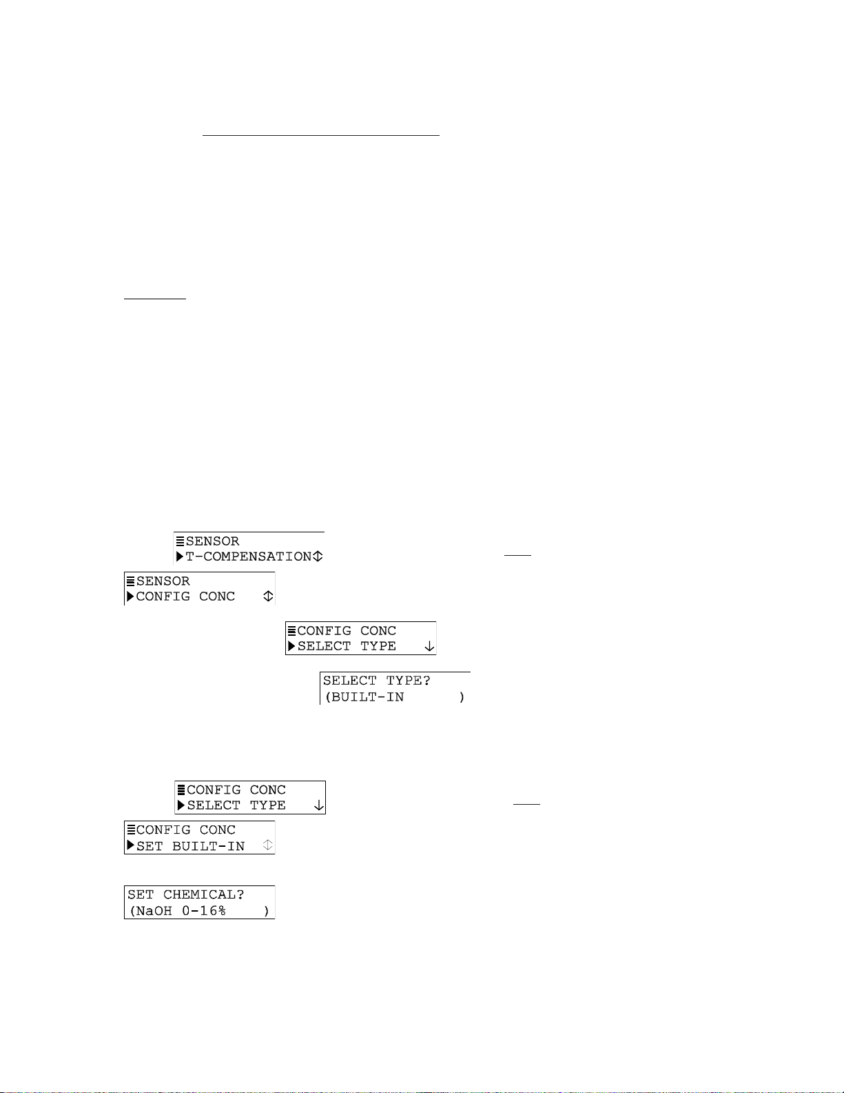
Selecting BUILT-IN Chemical Concentration Table
1. With the
.
2. Press ENTER key to display
3. Press ENTER key again to display
transmitter to use one of the built-in chemical concentration tables. (If screen shows
ØØ
USER-DEFINED, use
4. With “BUILT-IN” displayed, press ENTER key.
5. After the
6. Press ENTER key to display a chemical table selection screen like
Ø and
ØØ
.
. Use
screen displayed, press
××
× keys to select BUILT-IN.)
××
screen re-appears, press
ØØ
Ø and
ØØ
××
× keys to select the chemical concentration
××
ØØ
Ø key once to display
ØØ
.
. BUILT-IN configures
ØØ
Ø key once to display
ØØ
table that matches your solution, and press ENTER key to enter it:
Page 27
PAGE 27
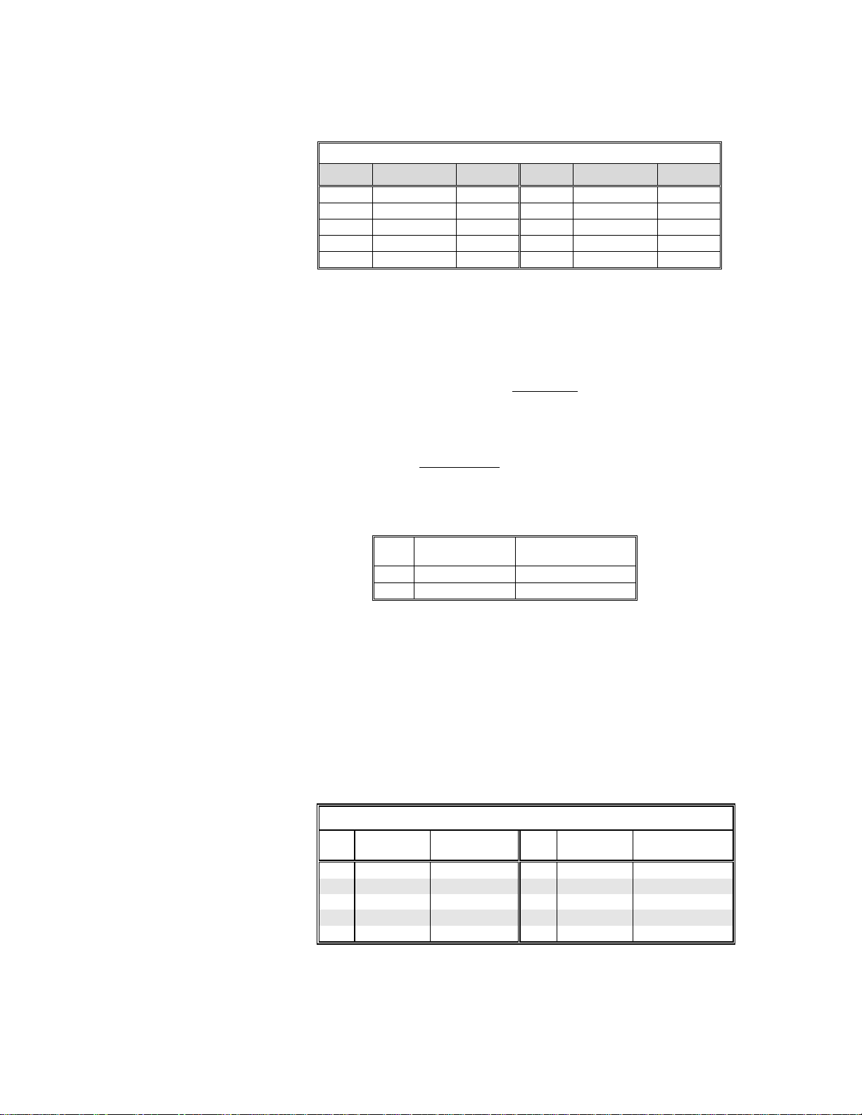
TABLE A -- BUILT-IN Chemical Concentration Tables
Solution Concentration
NaOH 0-16%
CaCl2 0-22%
HNO3 0-28%
HNO3 36-96%
H2SO4 0-30%
°C Range
0-100°C
15-55°C
0-50°C
0-50°C
0-115°C
Creating USER-DEFINED Concentration TABLE
If the solution being measured does not match any BUILT-IN chemical table, create a USERDEFINED table to convert measured conductivity into displayed % concentration.
Solution Concentration
H2SO4 40-80%
H2SO4 93-99%
H3PO4 0-40%
HCl 0-18%
HCl 22-36%
°C Range
0-115°C
0-115°C
0-75°C
0-65°C
0-65°C
NOTE: A USER-DEFINED table must contain
have up to ten. (More points improve measuring accuracy.) Each point must have a
conductivity value coordinate (shown as X) and a corresponding % concentration
value coordinate (shown as Y). The conductivity values and range are shown in units
selected by the “DISPLAY COND FORMAT” screen. Conductivity values for each
successive data point
must increase. Concentration values, shown in their selected
99.99% or 200.0% display format, must be different from each other and always
entered in order (increasing or decreasing). The table must be monotonic; that is, as
conductivity values increase, concentration values must always increase or decrease.
Data
Conductivity Value
Point
Pt. 1 0 µS/cm 0.00%
Pt. 2 2000 µS/cm 99.99%
(X coordinate)
To create your own USER-DEFINED table, edit this default table and, if needed, add
more points.
Recommendation: Before entering values, plan ahead and determine the
conductivity and corresponding % concentration values for each data point in
your table. Use TABLE B to conveniently organize and note your specific table
entry values:
at least two data points (Pt. 1 and Pt. 2) but can
% Concentration Value
(Y coordinate)
TABLE B -- Values for USER-DEFINED Concentration Table
Data
Conductivity
Point
Pt. 1 Pt. 6
Pt. 2 Pt. 7
Pt. 3 Pt. 8
Pt. 4 Pt. 9
Pt. 5 Pt. 10
Value
% Concentration
Value
Data
Point
Conductivity
Value
% Concentration
Value
Page 28
PAGE 28
NOTE: If the transmitter is calibrated, you can use the uncompensated conductivity
MEASURE screen to determine corresponding conductivity values.
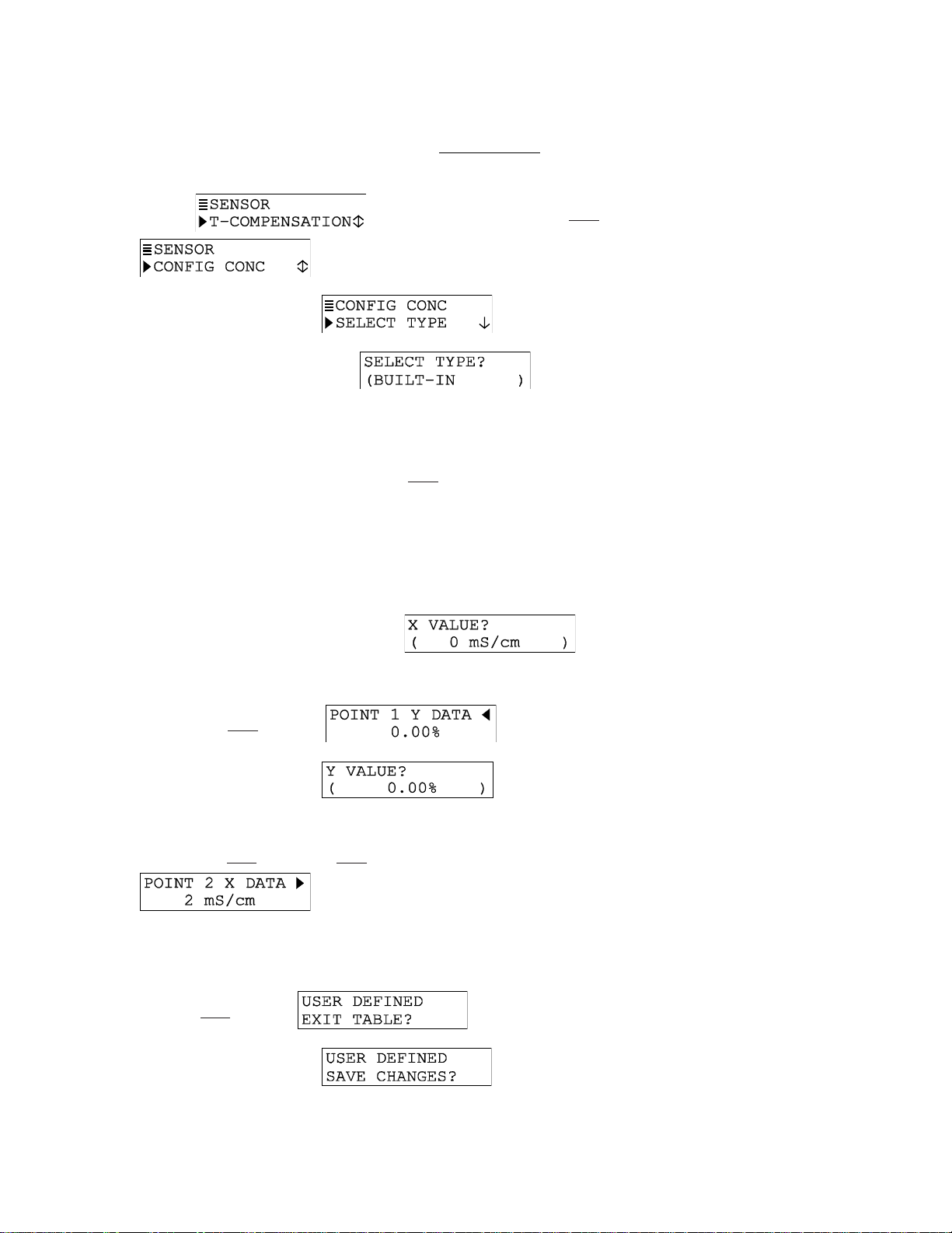
1. With the
.
2. Press ENTER key to display
3. Press ENTER key again to display
select “USER-DEFINED,” which configures the transmitter to use the special concentration table you create.
4. With “USER-DEFINED” displayed, press ENTER key.
5. After the screen re-appears, press
6. Press ENTER key to display a screen like . Using this screen and other similar data
point screens, enter data to create your table:
NOTE: To switch between X and Y coordinate screens of a data point, use
keys. To move between data points of an X or Y coordinate, use
A. Press ENTER key to display a screen like
keys to adjust the Point 1 conductivity value to an appropriate value, and press ENTER
key to enter it.
screen displayed, press
ØØ
Ø key once to display .
ØØ
ØØ
Ø key once to display
ØØ
.
ØØ
. Use
Ø or
ØØ
ÕÕ
Õ
and
ÕÕ
ØØ
Ø
and
ØØ
. Use arrow
××
× key to
××
ÖÖ
Ö
ÖÖ
××
×
keys.
××
B. Press
C. Press ENTER key to display
D. Press
E. Repeat steps 6A through 6D to enter the conductivity and corresponding % concentra-
F. After all X and Y coordinate values are entered for each data point in the table, press
G. Press ENTER key to display
H. Press ENTER key again to save the table.
ÖÖ
Ö key once to display .
ÖÖ
. Use arrow keys to adjust
the Point 1 % concentration value to correspond with the Point 1 conductivity value,
and press ENTER key to enter it.
ØØ
Ø key once and
ØØ
tion values for each remaining data point in the table.
ESC key once to display .
ÕÕ
Õ key once to display a screen like
ÕÕ
.
.
Page 29
PAGE 29
NOTE: If the table contains unacceptable coordinate values, the display shows a “CONFIRM
FAILURE” message. Pressing ENTER key displays the unacceptable coordinate(s)
TDS Measurement Setup
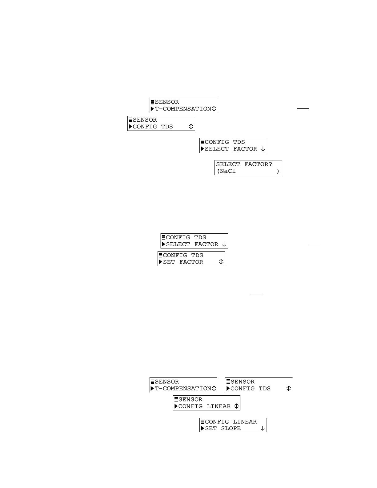
Define the conductivity-to-TDS conversion factor:
1. With the
.
2. Press ENTER key to display
3. Press ENTER key again to display
to select a conversion factor, and press ENTER key to enter it:
screen displayed, press
ØØ
Ø
key once to display
ØØ
.
. Use
ØØ
Ø and
ØØ
××
× keys
××
• NaCl: Built-in NaCl conductivity-to-TDS conversion factor.
• USER DEFINED: Conductivity-to-TDS conversion factor set by user (see step 4).
4. If “USER DEFINED” was selected, you must set a conductivity-to-TDS conversion
factor:
A. With the screen displayed, press
display .
B. Press ENTER key to display a screen like . Use arrow keys to adjust to a desired
conductivity-to-TDS conversion factor, and press ENTER key to enter it.
ØØ
Ø key once to
ØØ
C. After the screen re-appears, press ESC key once to return to the screen.
CONFIG LINEAR or CONFIG T-TABLE Temperature Compensation (configuration not
needed for other compensation methods)
Only when LINEAR or TEMP TABLE is the selected temperature compensation, must the
transmitter be further configured. If the built-in NATURAL WATER properties table or NONE
was selected, disregard this subsection — no compensation configuration is needed.
LINEAR Compensation Setup
Factory defaults for LINEAR compensation are 2.00%/°C slope and 25.0°C reference
temperature. These values are appropriate for most aqueous solutions. Use chemical
handbook tables to find values for uncommon solutions. To enter different values:
1. With the
ØØ
press
Ø key until screen appears.
ØØ
2. Press ENTER key to display
or screen displayed,
.
Page 30
PAGE 30
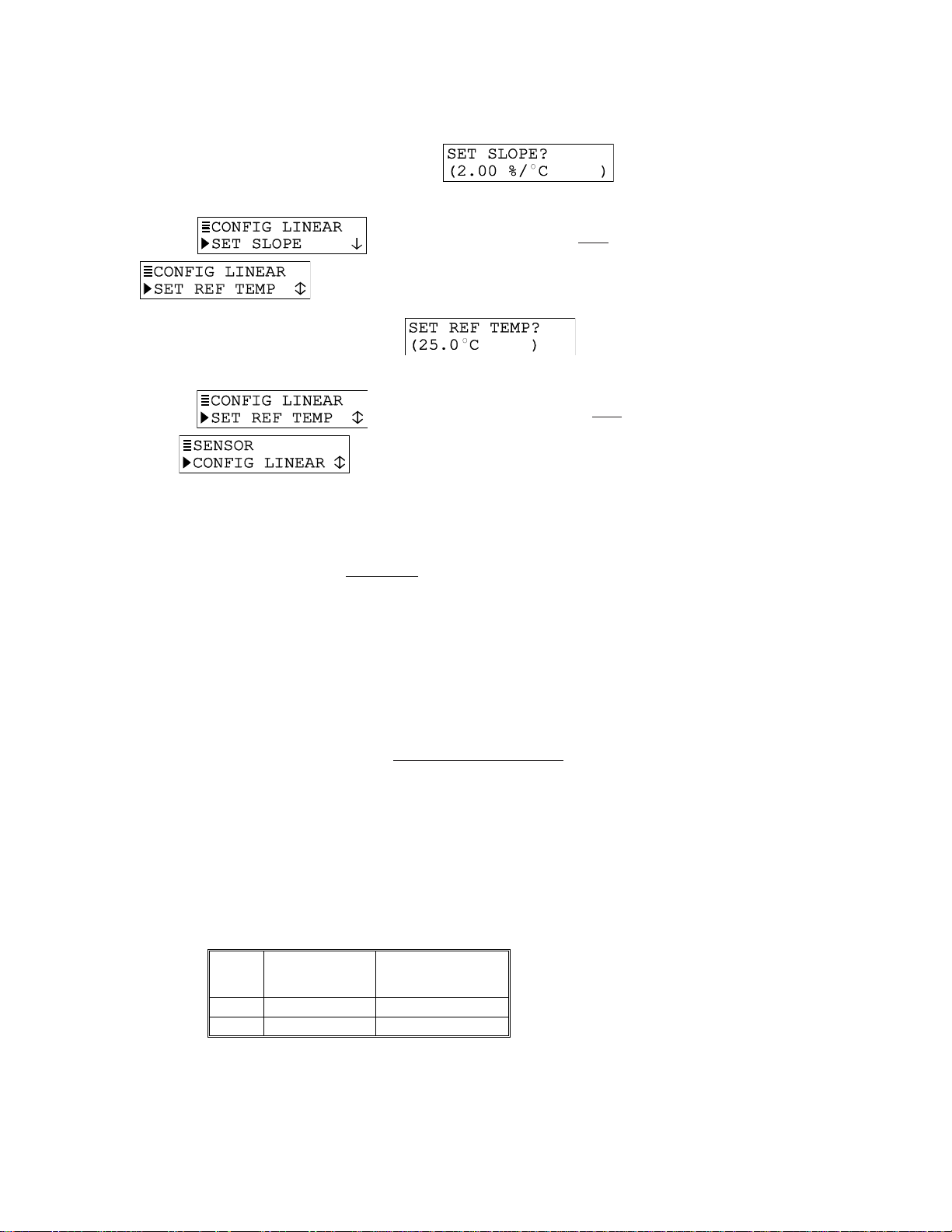
3. Press ENTER key again to display a screen like . Use
arrow keys to adjust to a desired slope, and press ENTER key to enter it.
4. After the
.
5. Press ENTER key to display a screen like
keys to adjust to a desired reference temperature, and press ENTER key to enter it.
6. After the
to the screen.
TEMP TABLE Compensation Setup
When special temperature compensation is required, you can create your own temperature
table to define the temperature compensation curve.
NOTE: The TEMP TABLE must contain at least two data points (Pt. 1 and Pt. 2) but can have
up to ten. (More points improve temperature compensation accuracy.) Each point
must have a temperature value coordinate (shown as X) and a corresponding ratio
coordinate (shown as Y). Temperature values must be between 0.0 and 200.0°C (or
32.0 and 392.0°F). Each entered temperature value must be different from all others.
Entered ratios, which are unit-less, must be between 0.00 and 99.99 and can have
the same value.
screen re-appears, press
screen re-appears, press ESC key once to return
ØØ
Ø key once to display
ØØ
. Use arrow
Use this equation to calculate the ratio value for each corresponding temperature
value:
Ratio Value (for each = Cond. Value at Ref. Temp.
corresponding temperature) Cond. Value at Noted Temp.
Example: Suppose the uncompensated or raw conductivity values are 100 mS/cm at a
25°C reference temperature, 120 mS/cm at 50°C, and 70 mS/cm at 15°C. Using this
equation, ratio values for each of the corresponding temperatures are:
For 25°C, ratio value = 100 / 100 or 1.00
For 50°C, ratio value = 100 / 120 or 0.83
For 15°C, ratio value = 100 / 70 or 1.43
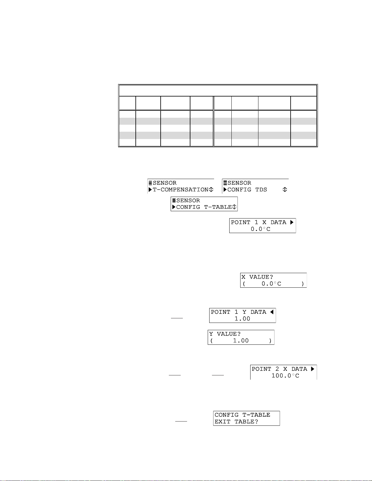
The default TEMP TABLE is:
Data
Point
Pt. 1
Pt. 2
Temperature
Value (X
coordinate)
°
C
0.0
°
C
100.0
Corresponding Ratio
Value (Y coordi nate)
1.00
1.00
To create your own TEMP TABLE, edit this default table and, if needed, add more data points.
Page 31
PAGE 31
Recommendation: Before entering values, plan ahead and determine the temperature and ratio
values for each data point in your table. Use TABLE C to conveniently organize and note your
specific table entry values:
TABLE C -- Values for TEMP TABLE
Data
°C Temp.
Point
Pt. 1 Pt. 6
Pt. 2 Pt. 7
Pt. 3 Pt. 8
Pt. 4 Pt. 9
Pt. 5 Pt. 10
(X)
1. With the or screen displayed,
ØØ
press
Ø key until screen appears.
ØØ
Raw
Cond.Value
Ratio
Value (Y)
Data
Point
°C Temp.
(X)
Raw
Cond. Value
Ratio
Value (Y)
2. Press ENTER key to display a screen like
screen and other similar data point screens, enter data to create your table:
NOTE: To switch between X and Y coordinate screens of a data point, use
move between data points of an X or Y coordinate, use
A. Press ENTER key to display a screen like
keys to adjust the Point 1 temperature to an appropriate value, and press ENTER
key to enter it.
B. Press
C. Press ENTER key to display
D. Press
E. Repeat steps 2A through 2D to enter the temperature and corresponding calcu-
ÖÖ
Ö key once to display .
ÖÖ
adjust the Point 1 ratio to match the calculated value corresponding to the Point 1
temperature, and press ENTER key to enter it.
ØØ
Ø key once and
ØØ
lated ratio values for each remaining data point in the table.
ÕÕ
Õ key once to display .
ÕÕ
ÕÕ
Õ
ÕÕ
ÖÖ
and
Ö
ÖÖ
. Use arrow keys to
. Using this
ØØ
Ø
and
ØØ
keys.
. Use arrow
××
×
keys. To
××
F. After all X and Y coordinate values are entered for each data point in the table,
press ESC key
once to display .
Page 32
PAGE 32
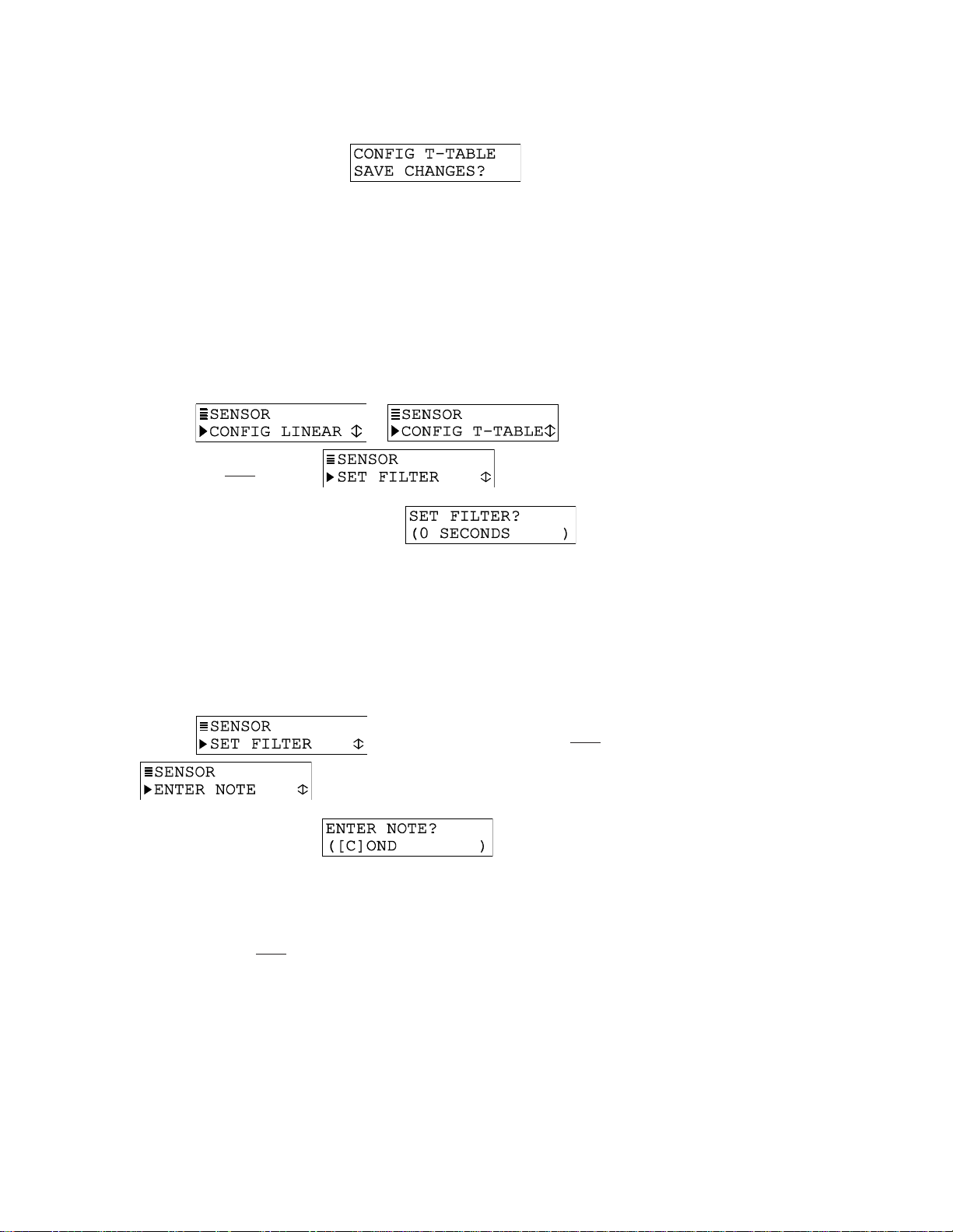
G. Press ENTER key to display .
H. Press ENTER key again to save the table.
NOTE: If the table contains unacceptable coordinate values, the display shows a “CONFIRM
FAILURE” message. Pressing ENTER key displays the unacceptable coordinate(s).
Set FILTER time
A time constant (in seconds) can be set to filter or “smooth out” the sensor signal. A minimum
value of “0 seconds” has no smoothing effect. A maximum value of “60 seconds” provides
maximum smoothing. Deciding what sensor signal filter time to use is a compromise. The higher
the filter time, the longer the sensor signal response time will be to a change in the actual
process value.
1. With the
ØØ
press
Ø key once to display .
ØØ
2. Press ENTER key to display a screen like . Use arrow
keys to adjust to a desired filter time, and press ENTER key to enter it.
ENTER NOTE (top line of MEASURE screen)
The top line of the MEASURE screen readouts that separately show the measurement,
temperature, and analog output values are factory set to read “COND.” This notation can be
changed, for example, to “BASIN 1” to tailor the transmitter MEASURE screen to the application.
The top line would then be “MEASURE BASIN 1.” The notation is limited to eight characters
which can be a combination of capital letters A through Z, numbers 0 through 9, spaces, #
symbols, hyphens, and periods.
1. With the screen displayed, press
.
2. Press ENTER key to display .
Create the desired notation on the second line:
or screen displayed,
ØØ
Ø key once to display
ØØ
××
A. Starting with extreme left character position, use
desired first character.
B. Press
C. Repeat procedure until desired notation is displayed.
3. Press ENTER key to enter the displayed notation.
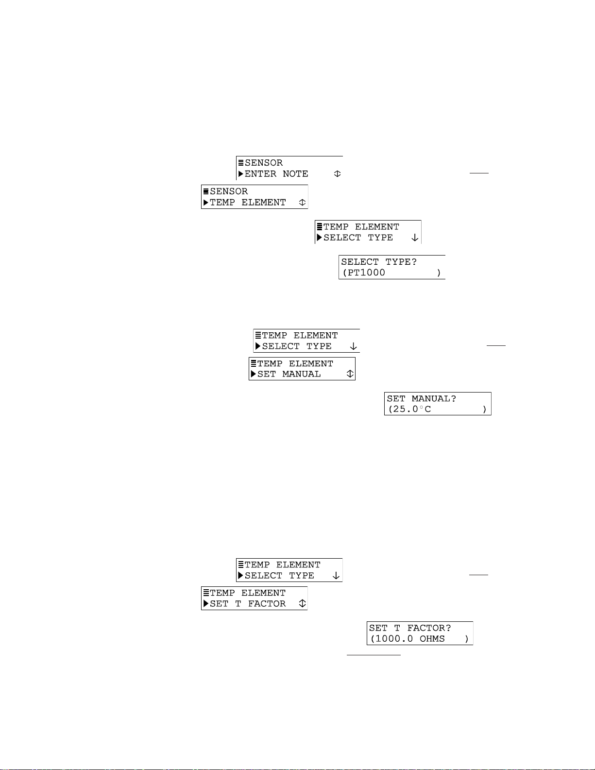
Select TEMP ELEMENT Type
The temperature element type is factory-set to “PT1000” for automatic temperature
compensation (defines built-in temperature element in electrodeless conductivity sensors).
ÖÖ
Ö key once to select the next character, and use
ÖÖ
its desired character.
× and
××
ØØ
Ø keys to select the
ØØ
××
× and
××
ØØ
Ø keys to select
ØØ
Page 33
PAGE 33
NOTE: When “PT1000” is selected but the element is not connected to the transmitter, a
“WARNING: CHECK STATUS” message will appear. To prevent or clear this
message, connect the element or select “MANUAL.”
To configure the transmitter for fixed MANUAL temperature compensation you must select
“MANUAL” and enter a specific temperature:
1. With the
.
2. Press ENTER key to display
3. Press ENTER key again to display
“MANUAL” for fixed manual temperature compensation, and press ENTER key to enter
it:
4. Now determine and enter a specific manual temperature compensation value:
A. With the
display
B. Press ENTER key to display a screen like . Use arrow
keys to adjust to a desired temperature for fixed MANUAL compensation, and
press ENTER key to enter it.
SET T FACTOR (sensor’s factory-certified “T” factor)
Each sensor is tested to provide a unique, certified temperature T FACTOR because:
screen displayed, press
screen displayed, press
.
ØØ
Ø key once to display
ØØ
.
ØØ
. Use
Ø key to select
ØØ
ØØ
Ø key once to
ØØ
• Temperature greatly affects conductivity measurement accuracy.
• The inherent ohm value of the Pt 1000 RTD temperature element varies slightly from
sensor to sensor, affecting temperature measurement accuracy.
By entering the sensor’s unique T FACTOR, the transmitter will provide the highest possible
measuring accuracy for both temperature and conductivity.
1. With the
.
2. Press ENTER key to display a screen like
keys to adjust the displayed value to exactly match the sensor’s factory-certified T
FACTOR, and press ENTER key to enter it.
screen displayed, press
ØØ
Ø key once to display
ØØ
. Use arrow
Page 34
PAGE 34
SPECIAL CASE — ALTERED SENSOR CABLE LENGTH
Changing the standard 20 ft. (6 m) sensor cable length, by shortening it or
adding an interconnect cable, affects temperature measuring accuracy. The
factory-certified T factor is based on standard cable length. To compensate for
altered cable length measuring error, change the certified T factor entry:
Shortened Sensor Cable: To increase the transmitter temperature reading to
match the known solution temperature, decrease the T factor by 3.85 ohms for
each °C difference.
Added Interconnect Cable: To decrease the transmitter temperature reading to
match the known solution temperature, increase the T factor by 3.85 ohms for
each °C difference.
Example: Suppose the known solution temperature is 50°C and the transmitter reads 53°C due
to interconnect cable resistance. Multiply the 3°C difference by 3.85 ohms to get 11.55.
Then increase the sensor T FACTOR by adding 11.55 to it and entering that value. If,
due to a shortened sensor cable, the transmitter was reading 3°C less than the known
solution temperature you would decrease the sensor T FACTOR by subtracting 11.55
from it.
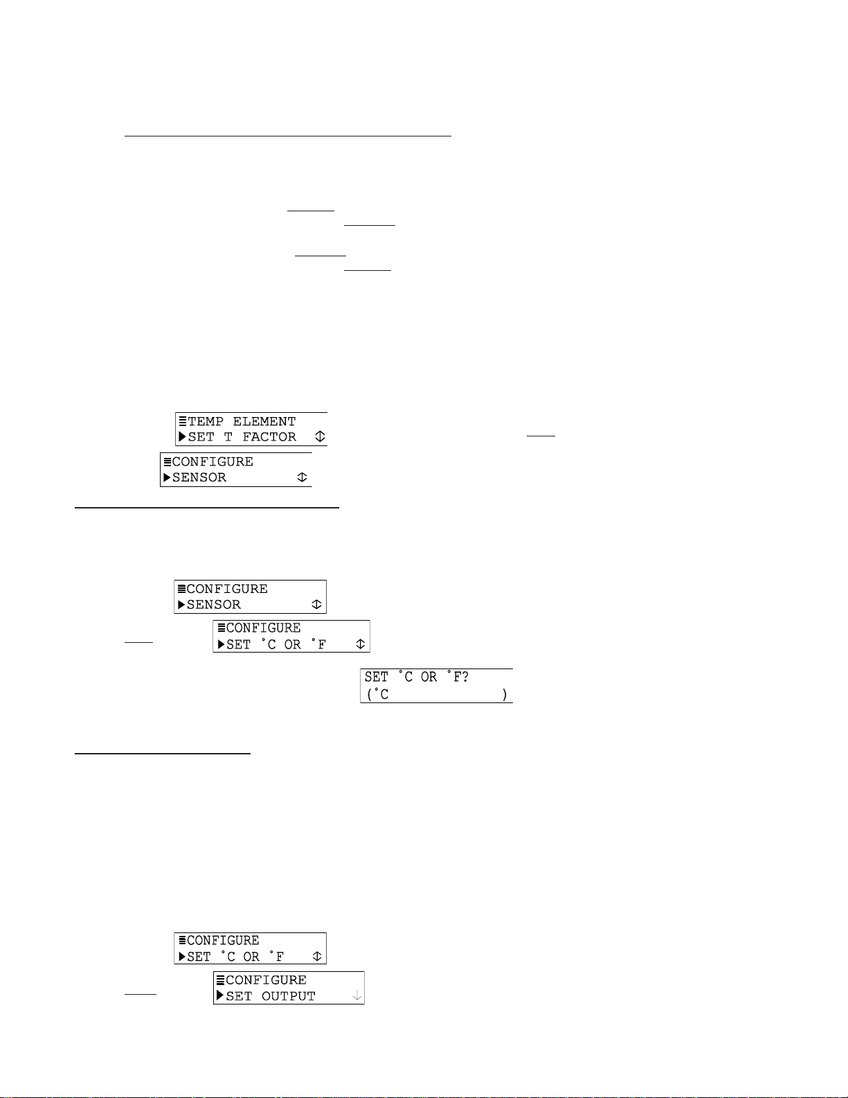
3. After the
to the screen.
7.3 7.3
SETSET
°°
C OR C OR
°°
7.3
SET
SETSET
7.3 7.3
The MEASURE screen can be set to display temperature values in °C or °F. In either case, the
display resolution for measured temperature is always “XX.X.”
1. With the screen displayed, press
2. Press ENTER key to display a screen like . Use
7.4 Configuring Analog Output7.4 Configuring Analog Output
7.4 Configuring Analog Output
7.4 Configuring Analog Output7.4 Configuring Analog Output
The transmitter provides an isolated 4-20 mA analog output. During normal measurement
operation, the output is active but can be held at the last measured value for up to 30 minutes by
using the “HOLD OUTPUT” function in the TEST/MAINT menu. (See Section 9.2 for details.)
During calibration, the output is automatically held at the last measured value and, upon
completion, returned to its active state.
F (temperature display format)F (temperature display format)
°
C OR
°
F (temperature display format)
°°
C OR C OR
°°
F (temperature display format)F (temperature display format)
twice to display .
keys to select the displayed temperature units (°C or °F), and press ENTER key to
enter it.
screen re-appears, press ESC key twice to return
××
× key — not
××
ØØ
Ø key —
ØØ
ØØ
Ø and
ØØ
××
×
××
SET PARAMETER (representation)
The output can be assigned to represent the SENSOR (measured conductivity, % concentration
or TDS) or measured TEMPERATURE.
1. With the screen displayed, press
twice to display .
××
× key — not
××
ØØ
Ø key —
ØØ
Page 35
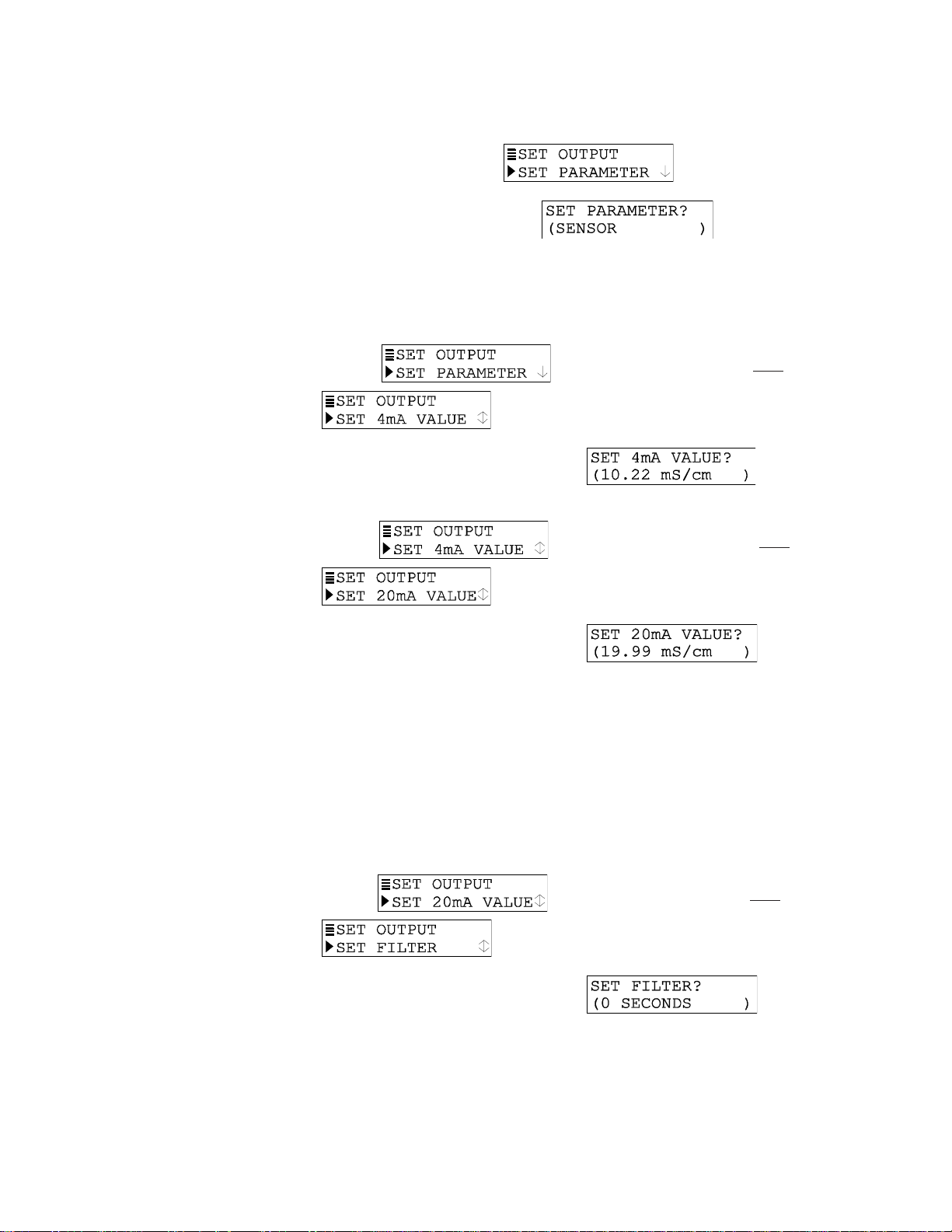
2. Press ENTER key to display .
PAGE 35
3. Press ENTER key again to display
to select the parameter the output will represent, and press ENTER key to enter it.
SET 4mA and 20 mA VALUES (range expand)
Parameter values can be set to define the endpoints at which the 4 mA and 20 mA analog
output values are desired.
1. With the
.
2. Press ENTER key to display a screen like . Use arrow
keys to set the value at which 4 mA is desired, and press ENTER key to enter it.
3. After the screen re-appears, press
.
4. Press ENTER key to display a screen like
screen displayed, press
ØØ
Ø key once to display
ØØ
ØØ
Ø
. Use
ØØ
ØØ
Ø key once to display
ØØ
××
×
and
. Use arrow
××
keys
keys to set the value at which 20 mA is desired, and press ENTER key to enter it.
NOTE: If the same values are set for 4 mA and 20 mA, the output automatically goes to and
remains at 20 mA.
SET FILTER Time
A time constant (in seconds) can be set to filter or “smooth out” the analog output signal. A
minimum value of “0 seconds” has no smoothing effect. A maximum value of “60 seconds”
provides maximum smoothing. Deciding what output filter time to use is a compromise. The
higher the filter time, the longer the analog output signal response time will be to a change in the
measured value.
1. With the screen displayed, press
.
2. Press ENTER key to display a screen like
keys to adjust to a desired filter time, and press ENTER key to enter it.
ØØ
Ø key once to display
ØØ
. Use arrow
Page 36
PAGE 36
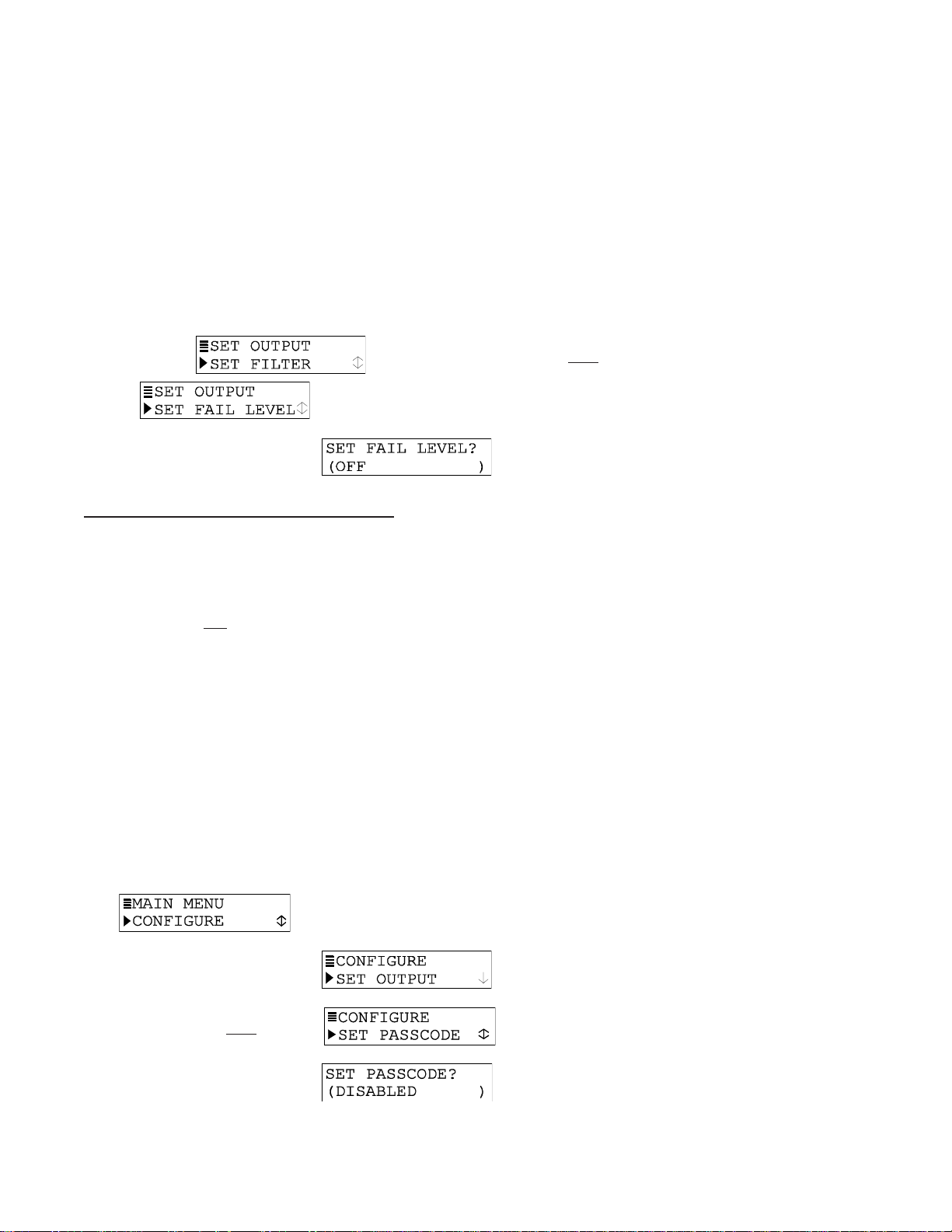
SET FAIL LEVEL Mode (off, 4 mA or 20 mA)
When a “WARNING CHECK STATUS” message appears, indicating that a system problem may
exist, the analog output can be set to respond in one of three ways:
• OFF: Output remains active.
• 4mA: Output automatically goes to and remains at 4 mA.
• 20mA: Output automatically goes to and remains at 20 mA.
To SET FAIL LEVEL mode to suit your application:
1. With the
.
2. Press ENTER key to display
select a response mode (OFF, 4mA or 20mA), and press ENTER key to enter it.
7.5 SET 7.5 SET
7.5 SET
7.5 SET 7.5 SET
The transmitter has a passcode feature to restrict access to configuration settings and
calibration to only authorized personnel.
PASSCODE PASSCODE
PASSCODE
PASSCODE PASSCODE
(feature(feature
(feature
(feature(feature
enabled or disabled)enabled or disabled)
enabled or disabled)
enabled or disabled)enabled or disabled)
screen displayed, press
ØØ
Ø
key once to display
ØØ
ØØ
. Use
Ø and
ØØ
××
× keys to
××
• DISABLED: With the passcode feature disabled, all configuration settings can be
displayed
and changed, and the transmitter can be calibrated.
• ENABLED: With the passcode feature enabled, all configuration settings can be
displayed — but they cannot be changed — and the CALIBRATE and TEST/MAINT
menus cannot be accessed without the passcode. When you attempt to change a
setting in the CONFIGURE menu by pressing the ENTER key, a displayed notification
requests passcode entry. A valid passcode entry saves the changed setting and
returns the display to the “MAIN MENU” branch selection screen. An incorrect
passcode entry causes the display to momentarily show an error notification before
returning to the “MAIN MENU” branch selection screen. There is no limit on attempts to
enter a valid passcode.
The passcode is factory set to “3 4 5 6.” It cannot be changed.
To enable or disable the passcode feature:
1. Press MENU key to display a “MAIN MENU” screen.
If the
2. Press ENTER key to display
3. Press
4. Press ENTER key to display
ØØ
Ø key once to display .
ØØ
select the desired passcode mode (DISABLED or ENABLED), and press ENTER key
to enter it.
screen is not showing, use
ØØ
Ø and
ØØ
.
. Use
××
× key to display it.
××
ØØ
Ø and
ØØ
××
× keys to
××
Page 37

This page intentionally left blank.
PAGE 37
Page 38
PAGE 38
7.6 Configuration Setting Summary7.6 Configuration Setting Summary
7.6 Configuration Setting Summary
7.6 Configuration Setting Summary7.6 Configuration Setting Summary
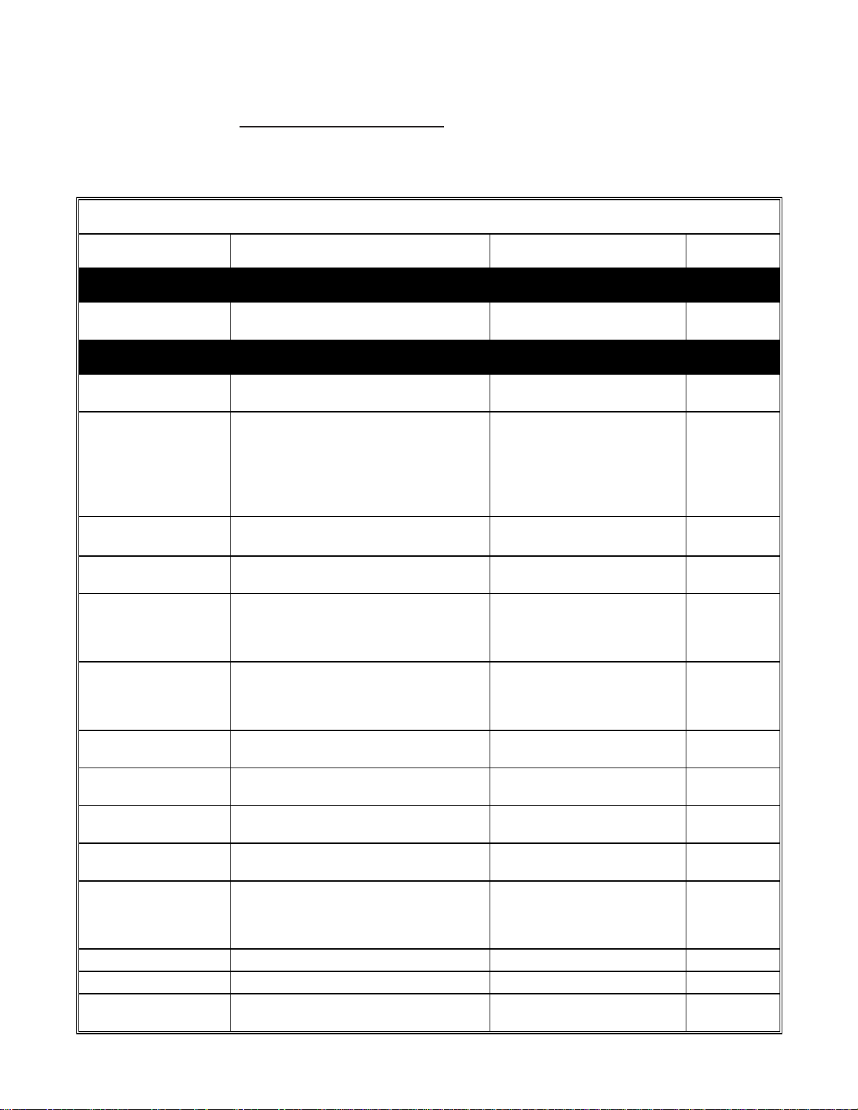
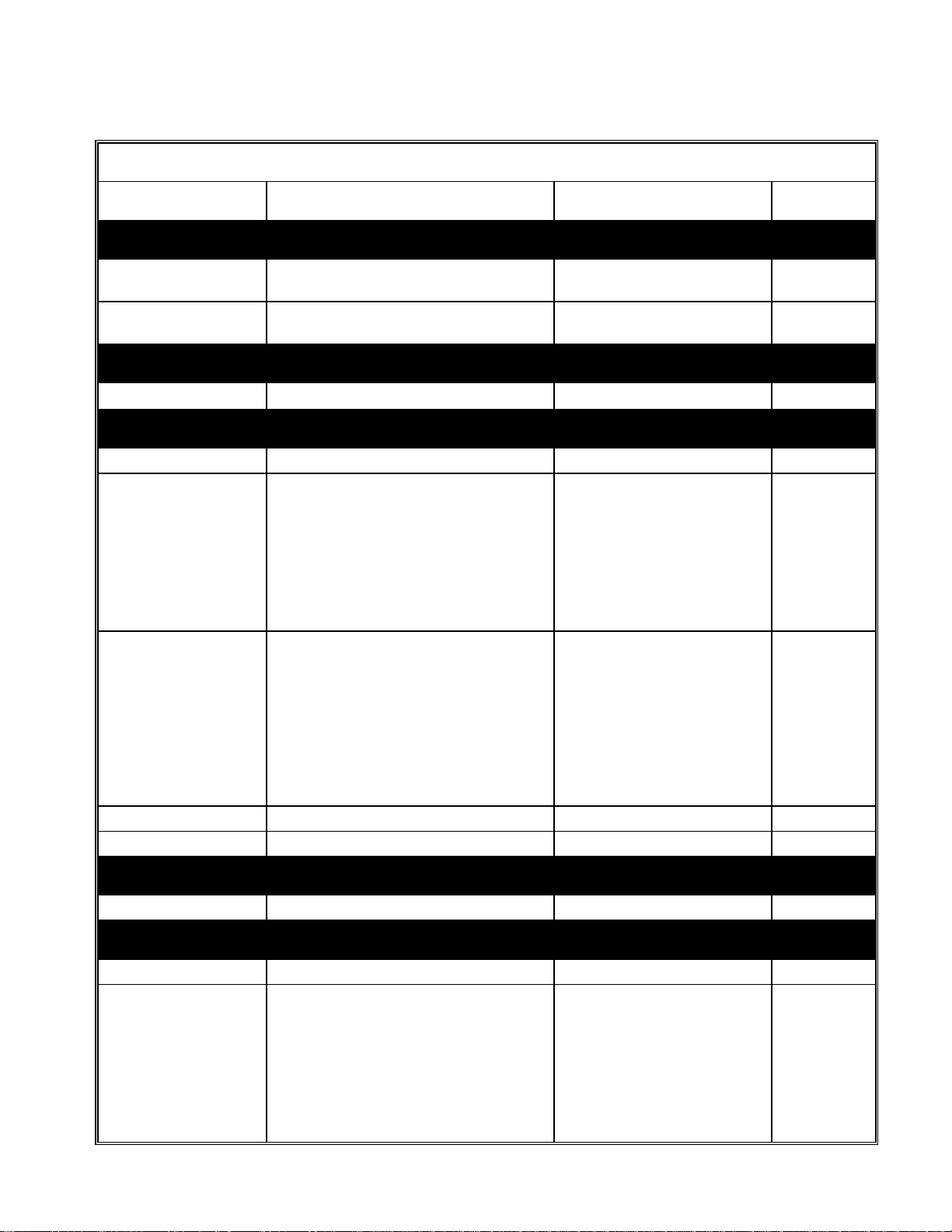
TABLE D lists all configuration settings and their entry ranges/choices and factory defaults,
categorized by basic functions.
TABLE D -- Transmitter Configuration Settings (Ranges/Choices and Defaults)
Displayed Screen Title Entry Range or Choices (where applicable) Factory Default Your Setting
LANGUAGE Setting
LANGU AGE? ENGLISH and S PA N ISH (French, German,
etc. may be substituted for Spanish)
SENSOR Settings
SELECT MEASURE? CONDUCTIVITY, CONCENTRATION or
TDS
DISPLAY FORMA T ?
(full scale value)
T-COMPENSATION? LINEAR, NATURAL WATER,
CONFIG CONC:
SELECT TYPE?
CONFIG CONC:
SET CHEMICAL?
CONFIG CONC:
USER DEFINED?
CONFIG TDS:
SELECT FACTOR?
CONFIG TDS:
SET FACTOR?
CONFIG LINEAR:
SET SLOPE?
CONFIG LINEAR:
SET REF TEMP?
CONFIG T-TABLE? Edit default table by entering up to 10
SET FILTER? 0-60 seconds 0 seconds
ENTER NOTE ? Replace COND with up to eight characters COND
TEMP E LEMENT:
SELECT TYPE?
CONDUCTIVITY:
µS/cm: 200.0, or 2000
mS/cm: 2.000, 20.00, 200.0 or 2000
S/cm: 2.000
CONCENT RATION: 99.99% or 200.0%
TDS: 9999 ppm
TEMP TABLE or NONE
BUILT-IN or US ER-D EF INED BUILT-IN
NaOH 0-16%,CaCl2 0-22%, HNO3 0-28%,
36-96%, H2SO4 0-30%, H2SO4 40-80% ,
HNO
3
93-99%, H3PO4 0-40%, HCl 0-18% or
H
2SO4
HCl 23-36%
Edit default table by entering up to 10
data points with conductivity X coordinates
and corresponding concentration Y
coordinates
NaCl or USER DEFINED NaCl
0.01-99.99 ppm/µS 0.49 ppm/µS
0-4.00% per °C 2.00% per °C
0-200.0°C or 32-392.0°F 25.0°C or 77.0°F
data points with temperature X coordinates
and corresponding ratio Y coordinates
(0-99.99)
PT1000 or MANUA L PT1000
ENGLISH
CONDUCTIVITY
CONDUCTIVITY: 200.0 mS/cm
CONCENTRATION: 99.99%
TDS: 9999 ppm
LINEAR at 2.00% per °C with
25.0°C reference temperature
Built-in NaOH 0-16% chemical
concentration table
Two point default conc. table:
Pt. 1: X = 0 µS/cm; Y = 0.00%
Pt. 2: X = 2000 µS/cm;
Y = 99.99%
Two point default temp. table:
Pt. 1: X = 0.0°C; Y = 1.00
Pt. 2: X = 100.0°C; Y = 1.00
Page 39
PAGE 39
TABLE D -- Transmitter Configuration Settings (Ranges/Choices and Defaults) -- continued
Displayed Screen Title Entry Range or Choices (where applicable) Factory Default Your Setting
SENSOR Settings (continued)
TEMP E LEM EN T :
SET T FACTOR?
TEMP E LEM EN T :
SET MA NUAL?
SET °C OR °F? °C or °F °C
SET PARAMETER? SENSOR or TEMPERATURE SENSOR
SET 4mA VALUE? CONDUCTIVITY:
SET 20mA VALUE? CONDUCTIVITY:
SET FILTER? 0-60 seconds 0 seconds
SET FAIL LEVEL? OF F, 4 mA or 20 m A OFF
950-1050 ohms 1000 ohms
0.0-200.0°C 25.0°C
TEMPERATURE Display Setting
OUTPUT Settings
CONDUCTIVITY:
µS/cm: 0-200.0, or 0-2000
mS/cm: 0-2.000, 0-20.00, 0-200.0 or 0-2000
S/cm: 0-2.000
CONCE NT R AT ION : 0-99.99% or 0-200.0%
TDS: 0-9999 ppm
TEMPERATURE:
-20.0 to +200.0°C or -4.0 to 392.0°F
µS/cm: 0-200.0 or 0-2000
mS/cm: 0-2.000, 0-20.00, 0-200.0 or 0-2000
S/cm: 0-2.000
CONCE NT R AT ION : 0-99.99% or 0-200.0%
TDS: 0-9999 ppm
TEMPERATURE:
-20.0 to +200.0°C or -4.0 to 392.0°F
µS/cm: 0
mS/cm: 0
S/cm: 0
CONC: 0.00% or 0.0%
TDS: 0 ppm
TEMPERATURE:
0.0°C o r 32.0°F
CONDUCTIVITY:
µS/cm: 200.0 or 2000
mS/cm: 2.000, 20.00, 200.0
or 2000
S/cm: 2.000
CONC: 99.99% or 200.0%
TDS: 9999 ppm
TEMPERATURE:
100.0°C or 212.0°F
PASSCO D E Setting
SET P A SSCODE? DISABLED or ENABLED DISABLED
TEST/MAINT Simulation Function Settings
SELECT SIM? SENSOR or TEMPERATURE SENSOR
SIM SENSOR? CONDUCTIVITY:
µS/cm: 0-200.0, or 0-2000
mS/cm: 0-2.000, 0-20.00, 0-200.0 or 0-2000
S/cm: 0-2.000
CONCE NT R AT ION : 0-99.99% or 0-200.0%
TDS: 0-9999 ppm
TEMPERATURE:
-20.0 to +200.0°C or -4.0 to 392.0°F
Present measured value of
selected parameter
Page 40

PAGE 40
Section 8 - TSection 8 - T
Section 8 - T
Section 8 - TSection 8 - T
8.1 Important Information8.1 Important Information
8.1 Important Information
8.1 Important Information8.1 Important Information
Each electrodeless conductivity sensor has a unique zero point and span. Consequently,
always zero the sensor when calibrating it for the first time (Section 8.2). Zeroing provides
the best possible measuring accuracy. After zeroing, calibrate for sensor span using one of the
available methods, and periodically thereafter to maintain best measurement accuracy. Over
time, some processes such as heavy slurries may plug the sensor hole, causing minor
measurement errors. The time between calibrations, and the rate of measurement drift can vary
considerably with each application and its specific conditions.
Calibration Tip! Establish a maintenance program to keep the sensor relatively
clean and the measuring system calibrated. The weekly or monthly intervals
between performing maintenance will be influenced by the characteristics of the
process solution, and can only be determined by operating experience.
Since the inherent ohm value of each sensor’s Pt 1000 RTD temperature element
varies slightly, each element is tested to provide a unique, factory-certified
temperature T FACTOR shown etched on the sensor housing. If this factor was
not previously entered during configuration in Section 7.2, subheading “SET T
FACTOR,” enter it now before zeroing or calibrating to provide the best
possible measuring accuracy.
NOTE: When the passcode feature is enabled (Section 7.5), you must successfully enter the
passcode before attempting to calibrate the transmitter.
ransmitter Calibrationransmitter Calibration
ransmitter Calibration
ransmitter Calibrationransmitter Calibration
An in-progress calibration can always be aborted by pressing the ESC key. After the
“ABORT: YES?” screen appears, do one of the following:
• Press ENTER key to abort. After the “CONFIRM ACTIVE?” screen appears, press
ENTER key to return the analog output to its active state (MEASURE screen appears).
××
• Press
continue calibration.
In addition to zeroing and calibrating sensor span, the analog output loop can also be calibrated.
Refer to Section 4.6 for details.
Zeroing/Calibration Tip! If a “CONFIRM FAILURE?” screen appears during
zeroing or calibration, press ENTER key to confirm. Then, use
select between “CAL: EXIT” or “CAL: REPEAT” and do
• With “(CAL: EXIT)” selected, press ENTER key. Then, after the “CONFIRM
ACTIVE?” screen appears, press ENTER key to return the analog output to its
active state (MEASURE screen appears).
• With “(CAL: REPEAT)” selected, press ENTER key to repeat zeroing or calibration.
ØØ
× or
Ø key to choose “ABORT: NO?” screen, and press ENTER key to
××
ØØ
××
× or
××
one of the following:
ØØ
Ø key to
ØØ
Page 41
PAGE 41
8.2 8.2
ZEROZERO
8.2
8.2 8.2
Zero the sensor if it is being calibrated for the first time. If not, disregard this subsection and
proceed with calibrating the sensor span (Section 4.3, 4.4 or 4.5).
NOTE: When using a new sensor, always perform a “RESET CALIBRATE” using the TEST/
1. Make sure that the sensor is dry before zeroing.
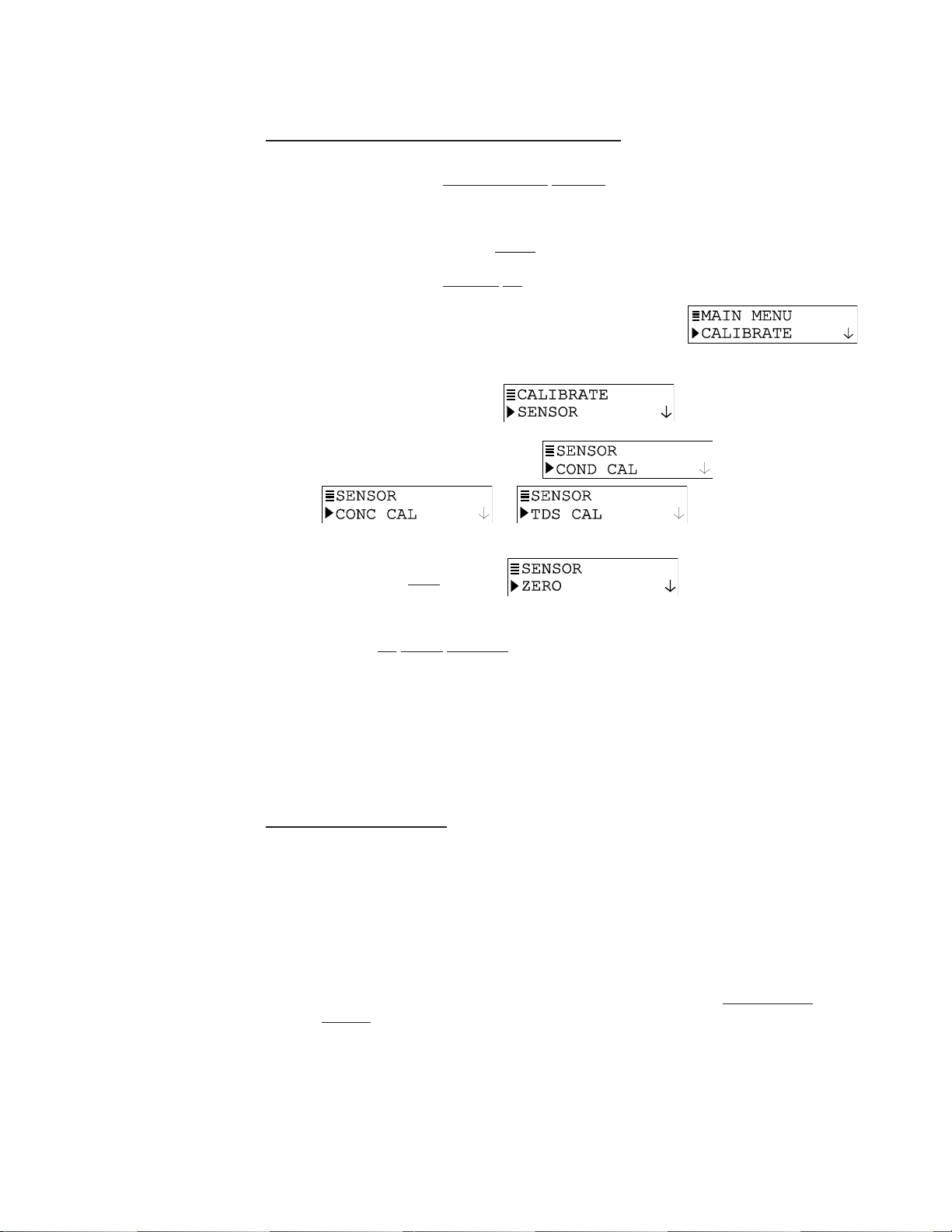
2. Press MENU key to display a “MAIN MENU” screen. If the
Procedure (first-time sensor calibration only) Procedure (first-time sensor calibration only)
ZERO
Procedure (first-time sensor calibration only)
ZEROZERO
Procedure (first-time sensor calibration only) Procedure (first-time sensor calibration only)
MAINT menu (Section 9.8)
screen is not showing, use
before zeroing and calibrating.
ØØ
××
Ø or
× key to display it.
ØØ
××
3. Press ENTER key to display
4. Press ENTER key again to display
, or (displayed screen depends
on selected measurement).
5. Press
6. Press ENTER key to display the “ZERO: IN DRY AIR?” screen.
7. With the dry sensor held in air, press ENTER key again to start automatic zeroing.
NOTE: During zeroing, the analog output is automatically “held” at the last measured value.
8. After the “ZERO: CONFIRM ZERO OK” screen appears, press ENTER key to end
9. After the “ZERO: CONFIRM ACTIVE?” screen appears, press ENTER key to return the
This completes zeroing the sensor.
8.3 Conductivity Calibration8.3 Conductivity Calibration
8.3 Conductivity Calibration
8.3 Conductivity Calibration8.3 Conductivity Calibration
After zeroing the sensor (first-time sensor calibration only), calibrate the sensor span using one
of these methods:
ØØ
Ø key twice to display .
ØØ
zeroing.
analog output to its active state (MEASURE screen appears).
.
,
• COND CAL Method: This method requires removing the sensor from the process,
immersing it into a conductivity reference solution, and entering a reference for
temperature compensation, and the known linear % per °C slope and conductivity
value of the reference solution.
• SAMPLE CAL Method: This method allows keeping the sensor installed in the
process, but requires you to obtain a process sample, determine its value by laboratory
analysis or comparison reading, and enter that value.
• ELECTRONIC CAL Method: This method requires that the sensor be removed from
the process and utilizes a decade resistance box to simulate conductivity rather than
an actual solution.
Page 42
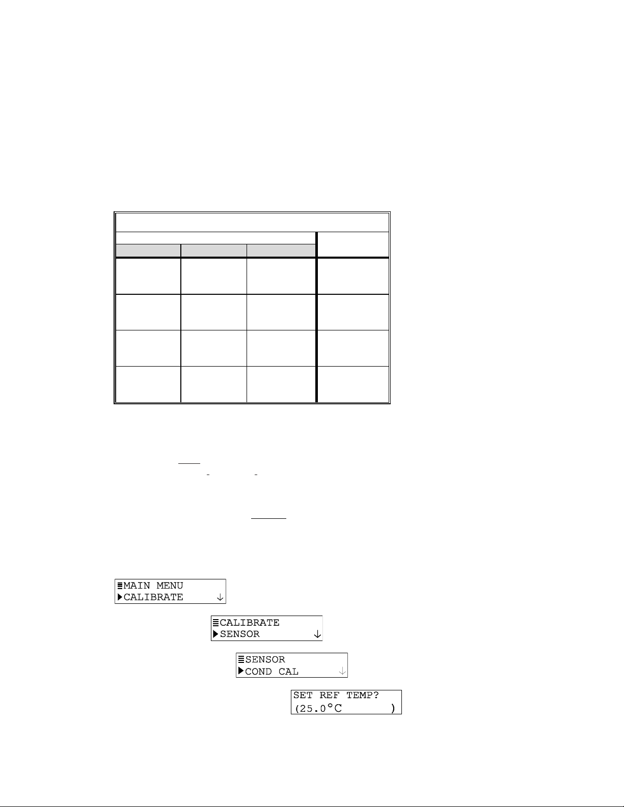
PAGE 42
COND CAL Method
1. Prepare the conductivity reference solution using your normal method. Its value should
be near the typical measured process value for best accuracy. When the value is
relatively low (between 200 and 100,000 microSiemens/cm), the data in TABLE E on
the next page can be used to prepare the reference solution. Add the listed grams of
pure, dried NaCl to one liter of high purity, de-ionized, CO
obtain the listed conductivity. Solution conductivity can be decreased by dilution with
de-ionized water.
TABLE E -- Conductivity Reference Solutions
Desired Soluti on V alue Grams NaCl
µS/cm mS/cm ppm (NaCl ) * To Be Added
200
500
1000
2000
3000
4000
5000
8000
10,000
20,000
50,000
100,000
0.20
0.50
1.00
2.00
3.00
4.00
5.00
8.00
10.00
20.00
50.00
100.00
100
250
500
1010
1530
2060
2610
4340
5560
11,590
31,950
72,710
-free water that is 25°C to
2
0.10
0.25
0.50
1.01
1.53
2.06
2.61
4.34
5.56
11.59
31.95
72.71
*When using ppm measuring scale for compounds other than NaCl, refer to
appropriate chemistry handbook for reference solution formulation.
2. Thoroughly rinse the clean sensor in de-ionized water. Then immerse the sensor in the
prepared reference solution. Important: Allow the sensor and solution tempera-
tures to equalize. Depending on their temperature differences, this may take up to 30
minutes.
NOTE: Suspend the sensor to prevent it from touching the container. Simply laying it into
the container will produce calibration error. If the sensor is tee-mounted, use a
smaller container. Ideally, convert a tee of the same size and material as the
mounting tee into a calibration container by sealing two of its ends.
3. Press MENU key to display a “MAIN MENU” screen.
ØØ
If the
4. Press ENTER key to display
5. Press ENTER key again to display
6. Press ENTER key again to display a screen like . The
default 25°C reference temperature is suitable for most applications. For another
reference, use arrow keys to adjust to a different temperature. In either case, press the
ENTER key.
screen is not showing, use
.
××
Ø or
× key to display it.
ØØ
××
.
Page 43
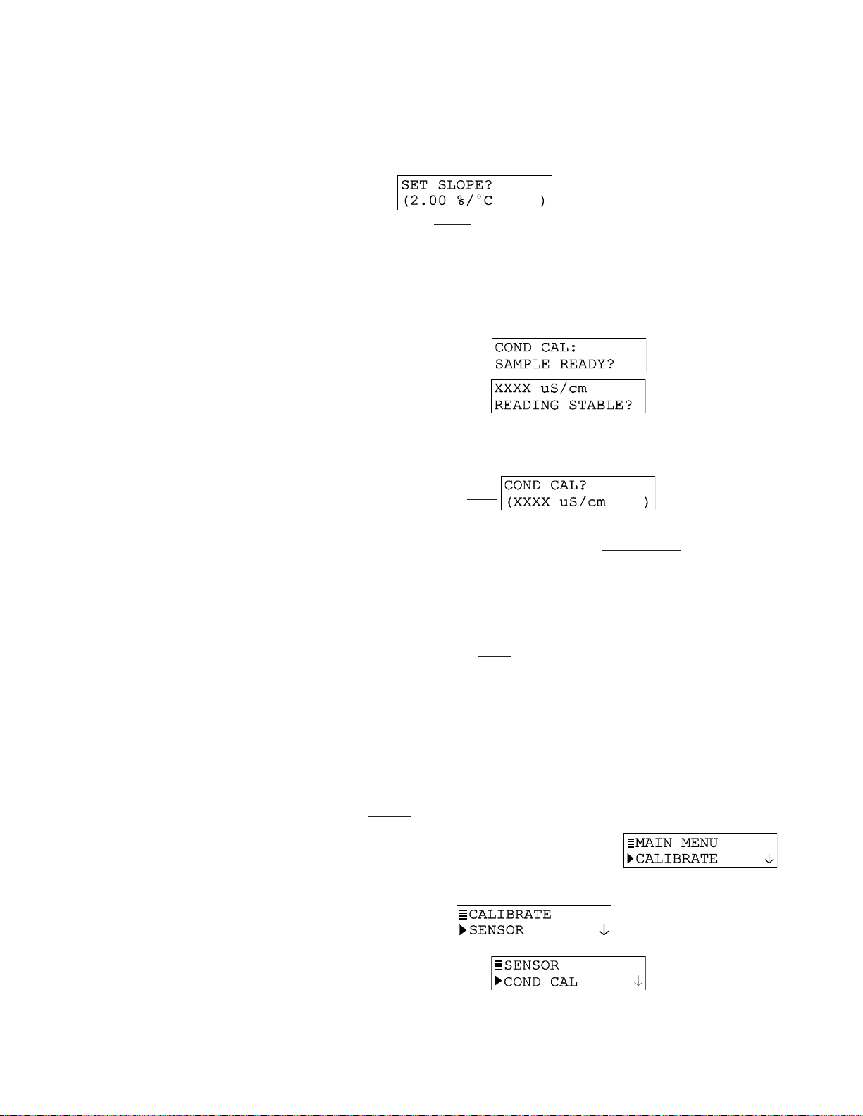
PAGE 43
NOTE: During calibration, the analog output is automatically “held” at the last measured
value.
7. After a screen like
slope value to match the
to enter the value.
NOTE: Measured values are normally compensated using the configured temperature
compensation method. However, during calibration the measured value is linearly
compensated by the entered reference temperature and slope value of the reference
solution.
8. With the sensor in solution and the
ENTER key to confirm. This active screen appears
showing the measured reference solution value.
9. Wait for the reading to stabilize which may take up to 30 minutes. Then press ENTER
key. The “PLEASE WAIT” screen may appear if the reading is still too unstable. After
the reading has stabilized, this
showing the “last measured” value.
10. Use arrow keys to adjust the “last-measured” value to exactly match the known value
of the reference solution.
11. Press ENTER key to enter the value and complete calibration (“CONFIRM CAL OK?”
screen appears).
known slope of the reference solution, and press ENTER key
static screen appears
appears, use arrow keys to adjust the
screen displayed, press
12. Re-install the sensor into the process.
13. Press ENTER key to display the active measurement reading on the “CONFIRM
ACTIVE?” output status screen. When the reading corresponds to the actual typical
process value, press ENTER key again to return the analog output to its active state
(MEASURE screen appears).
This completes COND CAL calibration
SAMPLE CAL Method
The “SAMPLE CAL” method enables the sensor to remain installed in the process.
1. Obtain a sample of the process solution and determine its value using laboratory
analysis or a recently calibrated portable meter.
2. Press MENU key to display a “MAIN MENU” screen. If the
ØØ
screen is not showing, use
3. Press ENTER key to display
4. Press ENTER key again to display
××
Ø or
× key to display it.
ØØ
××
.
.
Page 44
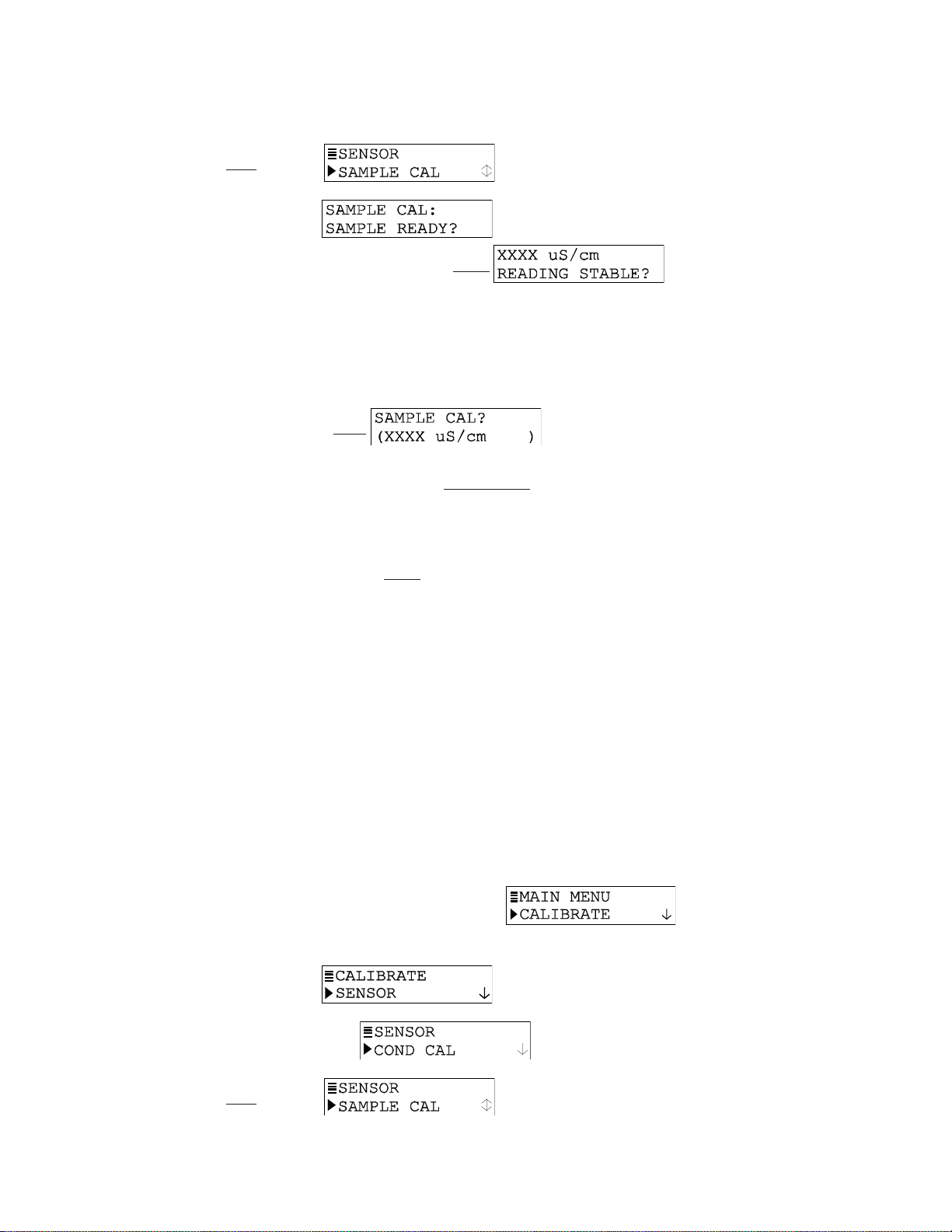
PAGE 44
5. Press
6. Press ENTER key to display
NOTE: During calibration, the analog output is automatically “held” at the last measured
7. Wait for the reading to stabilize which may take up to 30 minutes. Then press ENTER
8. Use arrow keys to adjust the displayed value to exactly match the known value of the
9. Press ENTER key to enter the value and complete calibration (“CONFIRM CAL OK?”
10. Press ENTER key again to display the active measurement reading on the “CONFIRM
This completes SAMPLE CAL calibration.
ØØ
Ø key once to display .
ØØ
. With the sensor in the
process, press ENTER key again to confirm. This
screen appears showing the measurement reading.
value.
key. The “PLEASE WAIT” screen may appear if the reading is still too unstable. After
the reading has stabilized, this
showing the “last measured” value.
process sample.
screen appears).
ACTIVE?” output status screen. When the reading corresponds to the actual typical
process value, press ENTER key again to return the analog output to its active state
(MEASURE screen appears).
static screen appears
active
ELECTRONIC CAL Method (only to be used after consulting with the factory)
The “ELECTRONIC CAL” method requires that the sensor be removed from the process and
utilizes a decade resistance box to simulate conductivity rather than an actual solution.
1. Determine the typical conductivity in µS/cm for the application.
2. Calculate the required loop resistance by dividing 470 million by the desired conductivity in µS/cm (or 470 divided by the desired conductivity in S/cm)
3. Wrap (9) nine loops of wire (18-22 AWG) around and through the center of the sensor.
4. Connect this wire to a 1% or better decade resistance box (the decade box forms a
10th loop). Set the decade box to the value calculated above.
5. Press MENU key to display a “MAIN MENU” screen. If the
ØØ
screen is not showing, use
6. Press ENTER key to display
7. Press ENTER key again to display
8. Press
ØØ
Ø key once to display .
ØØ
××
Ø or
× key to display it.
ØØ
××
.
.
Page 45

PAGE 45
9. Press ENTER key to display . With the decade box
connected, press ENTER key again to confirm. This active
screen appears showing the measurement reading.
NOTE: During calibration, the analog output is automatically “held” at the last measured
value.
10. Wait for the reading to stabilize which may take up to 30 minutes. Then press ENTER
key. The “PLEASE WAIT” screen may appear if the reading is still too unstable. After
the reading has stabilized, this
showing the “last measured” value.
11. Use arrow keys to adjust the displayed value to exactly match the desired conductivity
value used in the calculation..
12. Press ENTER key to enter the value and complete calibration (“CONFIRM CAL OK?”
screen appears).
13. Press ENTER key again to display the active measurement reading on the “CONFIRM
ACTIVE?” output status screen. When the reading corresponds to the actual typical
process value, press ENTER key again to return the analog output to its active state
(MEASURE screen appears).
This completes ELECTRONIC CAL calibration.
8.4 % Concentration Calibration8.4 % Concentration Calibration
8.4 % Concentration Calibration
8.4 % Concentration Calibration8.4 % Concentration Calibration
After zeroing the sensor (first-time sensor calibration only), calibrate the sensor span using one
of these methods:
static screen appears
• CONC CAL Method: This method requires you to immerse the sensor into a prepared
% concentration reference solution of known value, or to keep the sensor installed in
the process while obtaining a process sample. When keeping the sensor installed,
determine the process value by laboratory analysis or comparison reading. In either
case, enter the known reference solution or sample % concentration value.
• COND CAL Method: This method requires removing the sensor from the process,
immersing it into a
compensation temperature, and entering the known linear % per °C slope and conductivity value of the reference solution. The conductivity reference solution should have
an equivalent, uncompensated value that corresponds with the normal % concentration
value of the process.
conductivity reference solution, entering a reference for temperature
1. Depending on the situation, do one of the following:
• When Keeping Sensor Installed:
Obtain a sample of the process solution and determine its value using laboratory
analysis or a recently calibrated portable meter.
• When Immersing Sensor in Reference Solution:
A. Prepare a % concentration reference solution using your normal method. To
achieve accurate calibration, the reference solution must have the same
chemical composition as the process. Also, its value should be near the typical
measured process value.
Page 46
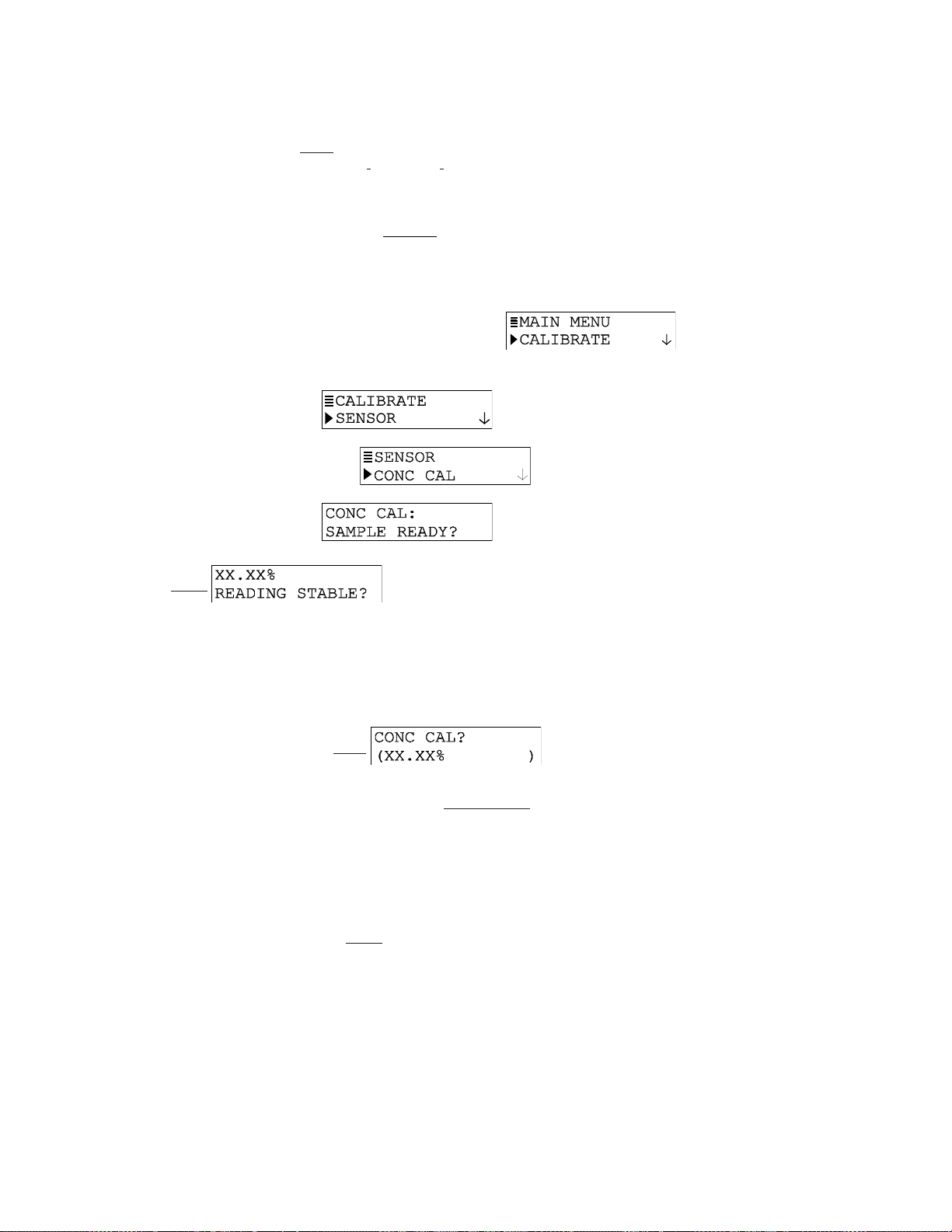
PAGE 46
B. Thoroughly rinse the clean sensor in de-ionized water. Then immerse the sensor in
the prepared reference solution. Important: Allow the sensor and solution
temperatures to equalize. Depending on their temperature differences, this may
take up to 30 minutes.
NOTE: Suspend the sensor to prevent it from touching the container. Simply laying it into
the container will produce calibration error. If the sensor is tee-mounted, use a
smaller container. Ideally, convert a tee of the same size and material as the
mounting tee into a calibration container by sealing two of its ends.
2. Press MENU key to display a “MAIN MENU” screen. If the
ØØ
××
Ø
screen is not showing, use
ØØ
×
or
key to display it.
××
3. Press ENTER key to display
4. Press ENTER key again to display
5. Press ENTER key to display
process (or % concentration reference solution), press ENTER key again to confirm.
This
active screen appears showing the measurement
reading.
NOTE: During calibration, the analog output is automatically “held” at the last measured
value.
6. Wait for the reading to stabilize which may take up to 30 minutes. Then press ENTER
key. The “PLEASE WAIT” screen may appear if the reading is still too unstable. After
the reading has stabilized, this static screen appears
showing the “last measured” value.
7. Use arrow keys to adjust the displayed value to exactly match the known value of the
process sample (or % concentration reference solution).
8. Press ENTER key to enter the value and complete calibration (“CONFIRM CAL OK?”
screen appears).
.
.
. With the sensor in the
9. If the sensor was immersed in a reference solution, re-install the sensor into the
process.
10. Press ENTER key to display the active measurement reading on the “CONFIRM
ACTIVE?” output status screen. When the reading corresponds to the actual typical
process value, press ENTER key again to return the analog output to its active state
(MEASURE screen appears).
This completes CONC CAL calibration.
Page 47
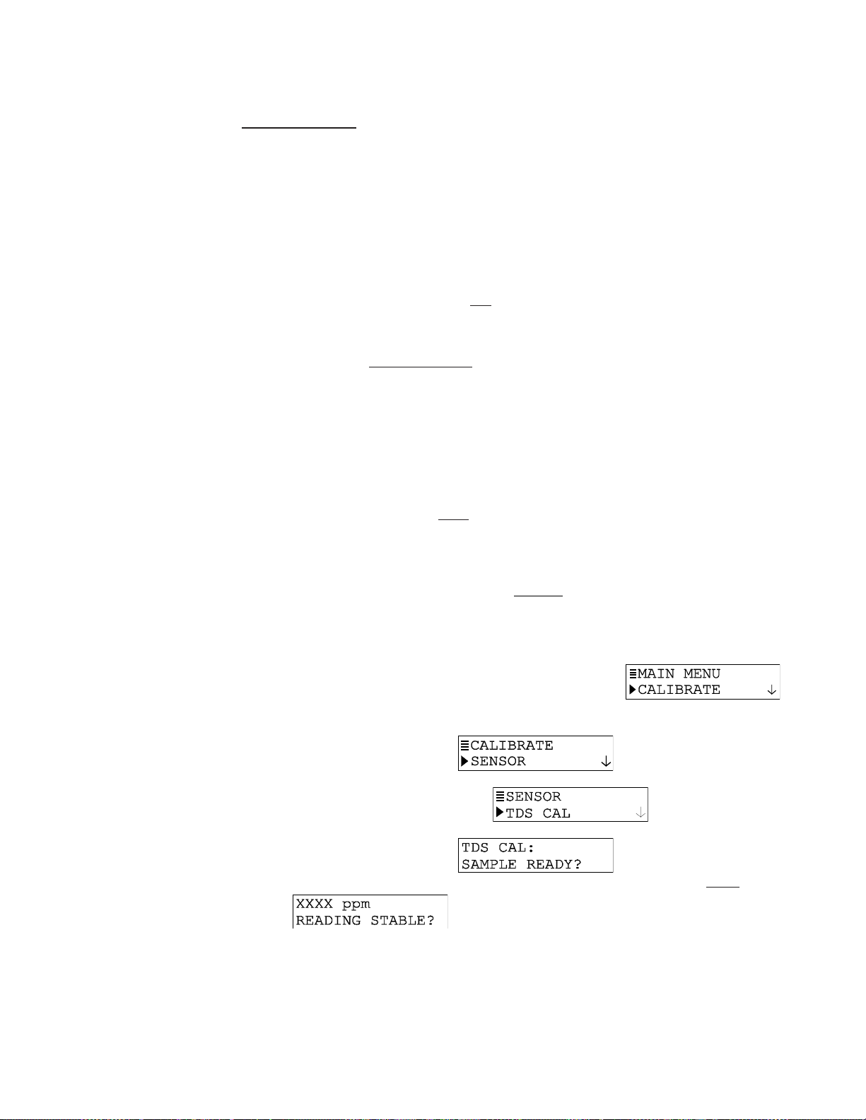
PAGE 47
8.4 TDS Calibration8.4 TDS Calibration
8.4 TDS Calibration
8.4 TDS Calibration8.4 TDS Calibration
When the transmitter is set to measure % concentration but you want to calibrate using a
conductivity reference solution, please refer to Section 8.3, subsection “COND CAL Method” and
follow steps 1 through 13.
When the transmitter is set to measure TDS, only the “TDS CAL” method is available to calibrate
sensor span. This method requires you to immerse the sensor into a properly prepared TDS
reference solution of known ppm value, or to keep the sensor installed in the process while
obtaining a process sample. In either case, enter the known reference solution or sample ppm
value.
1. Depending on the situation, do
• When Keeping Sensor Installed:
Obtain a sample of the process solution and determine its value using laboratory
analysis or a recently calibrated portable meter.
• When Immersing Sensor in Reference Solution:
A. Prepare a TDS reference solution using your normal method. To achieve accu-
rate calibration, the reference solution must have the same chemical composition as the process. Also, its value should be near the typical measured
process value. When the value is between 100 and 72,710 ppm NaCl, the data in
step 1 and TABLE E of Section 4.3, subsection “COND CAL Method” can be used
to prepare the reference solution.
B. Thoroughly rinse the clean sensor in de-ionized water. Then immerse the sensor in
the prepared reference solution. Important: Allow the sensor and solution
temperatures to equalize. Depending on their temperature differences, this may
take up to 30 minutes.
NOTE: Suspend the sensor to prevent it from touching the container. Simply laying it into
the container will produce calibration error. If the sensor is tee-mounted, use a
smaller container. Ideally, convert a tee of the same size and material as the
mounting tee into a calibration container by sealing two of its ends.
2. Press MENU key to display a “MAIN MENU” screen. If the
one of the following:
ØØ
screen is not showing, use
3. Press ENTER key to display
4. Press ENTER key again to display
5. Press ENTER key to display
process (or reference solution), press ENTER key again to confirm. This active
NOTE: During calibration, the analog output is automatically “held” at the last measured
value.
6. Wait for the reading to stabilize which may take up to 30 minutes. Then press ENTER
key. The “PLEASE WAIT” screen may appear if the reading is still too unstable. After
××
Ø or
× key to display it.
ØØ
××
.
.
. With the sensor in the
screen appears showing the measurement reading.
Page 48

PAGE 48
the reading has stabilized, this static screen appears
showing the “last measured” value.
7. Use arrow keys to adjust the displayed value to exactly match the known value of the
process sample (or TDS reference solution).
8. Press ENTER key to enter the value and complete calibration (“CONFIRM CAL OK?”
screen appears).
9. If the sensor was immersed in a reference solution, re-install the sensor into the
process.
10. Press ENTER key again to display the active measurement reading on the “CONFIRM
ACTIVE?” output status screen. When the reading corresponds to the actual typical
process value, press ENTER key again to return the analog output to its active state
(MEASURE screen appears).
This completes TDS CAL calibration.
Page 49
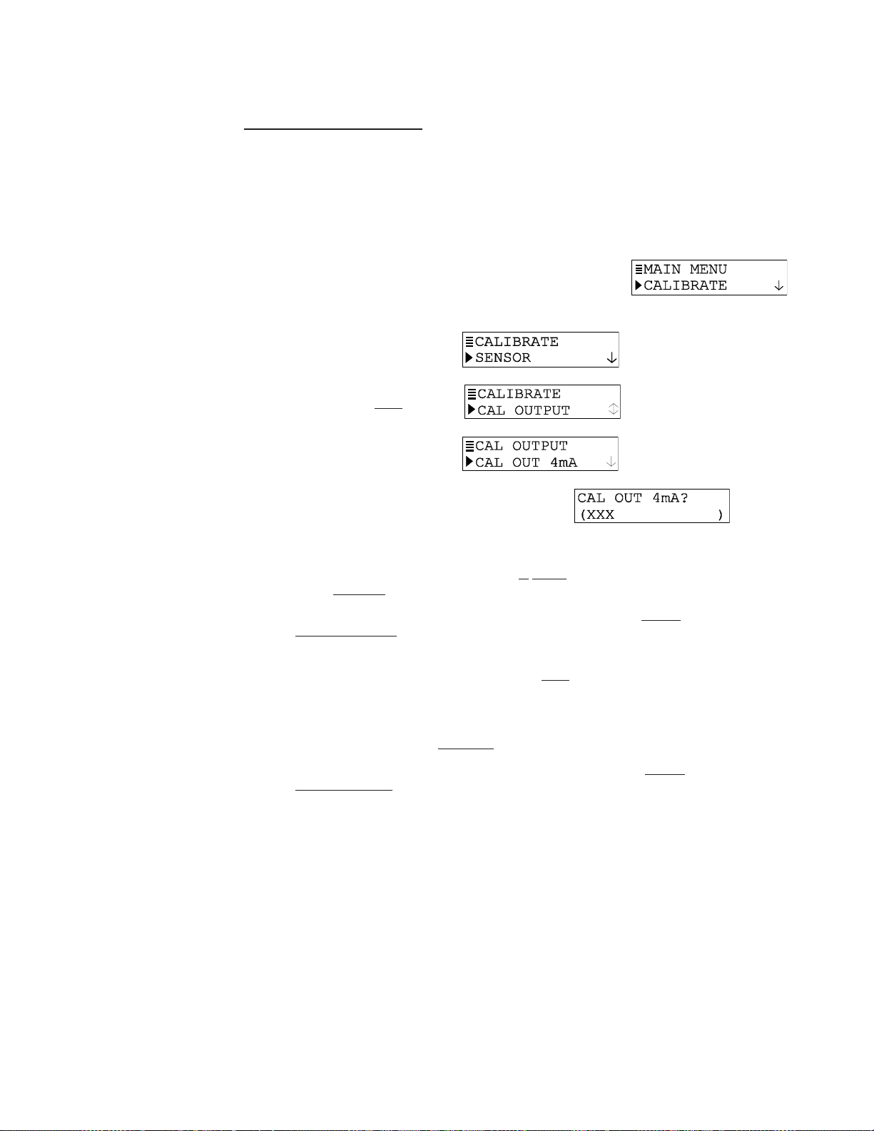
PAGE 49
8.6 Analog Output Calibration8.6 Analog Output Calibration
8.6 Analog Output Calibration
8.6 Analog Output Calibration8.6 Analog Output Calibration
The transmitter analog output is factory-calibrated. However, it can be re-calibrated if desired.
NOTE: When the passcode feature is enabled (Section 7.5), you must successfully enter the
passcode before attempting to calibrate the analog output.
Also, the transmitter adjustment range for output values during calibration is ± 2 mA.
1. Press MENU key to display a “MAIN MENU” screen. If the
ØØ
screen is not showing, use
2. Press ENTER key to display
××
Ø or
× key to display it.
ØØ
××
3. Press
4. Press ENTER key to display
5. Press ENTER key again to display a screen like
6. Connect a calibrated digital multimeter
7. Use arrow keys to adjust the minimum output value to read exactly “4.00 mA” on the
8. After the screen re-appears, press
9. Press ENTER key to display a screen like . Once again the displayed value is “counts”
10. Now measure the actual
11. Use arrow keys to adjust the maximum output value to read exactly “20.00 mA” on the
This completes analog output calibration.
ØØ
Ø key once to display .
ØØ
.
. The
displayed value is “counts” — not mA — that dynamically change as the output is
adjusted.
in series with the loop load to measure the
actual minimum mA output in the loop.
digital multimeter — not the transmitter display, and press ENTER key to complete
calibration of the minimum endpoint value.
ØØ
Ø key once to display .
ØØ
— not mA — that dynamically change as the output is adjusted.
maximum mA output in the loop with the digital multimeter.
digital multimeter — not the transmitter display, and press ENTER key to complete
calibration of the maximum endpoint value.
Page 50
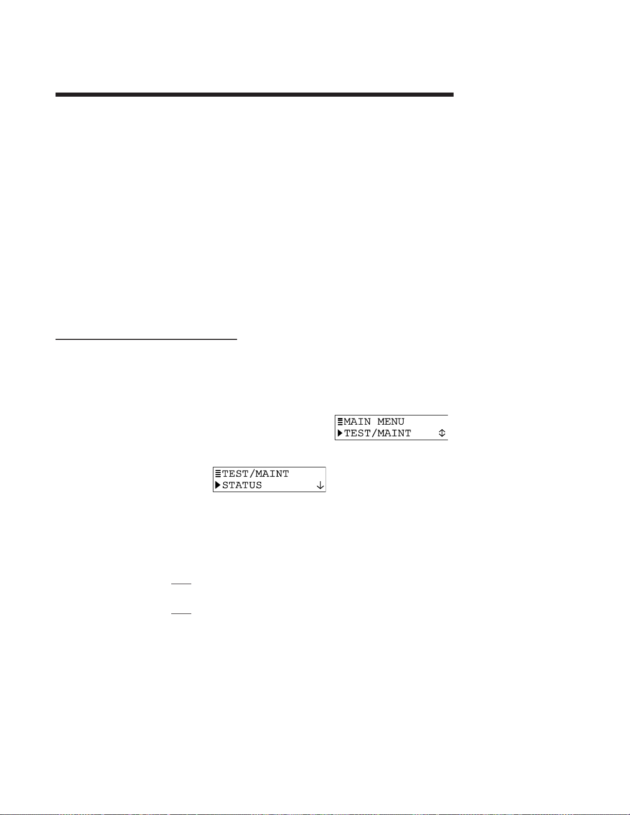
PAGE 50
Section 9 - TSection 9 - T
Section 9 - T
Section 9 - TSection 9 - T
The transmitter has TEST/MAINT menu screens to:
esting & Maintenanceesting & Maintenance
esting & Maintenance
esting & Maintenanceesting & Maintenance
• Check operating status of the transmitter and sensor.
• Hold analog output at its last measured value.
• Provide analog output test signal to confirm operation of connected device.
• Identify transmitter firmware EPROM version.
• Simulate a measurement or temperature signal to exercise the measurement loop.
• Reset configuration — not calibration — values to defaults.
• Reset calibration — not configuration — values to defaults.
NOTE: When the passcode feature is enabled (Section 7.5), you must successfully enter the
passcode before attempting to use the TEST/MAINT menu screens.
9.1 ST9.1 ST
AA
9.1 ST
9.1 ST9.1 ST
The system diagnostic capabilities of the transmitter enable you to check the operating status of
the transmitter and sensor. The MEASURE screen will flash the “WARNING CHECK STATUS”
message when a system diagnostic “fail” condition has been detected. To determine the
condition causing the warning, display the “STATUS” screens.
TUS Check (transmitter and sensor)TUS Check (transmitter and sensor)
A
TUS Check (transmitter and sensor)
AA
TUS Check (transmitter and sensor)TUS Check (transmitter and sensor)
1. Press MENU key to display a “MAIN MENU” screen. If the
ØØ
screen is not showing, use
2. Press ENTER key to display
3. Press ENTER key again to display “STATUS: ANALYZER OK” screen. This screen
confirms that the transmitter is operating properly. If “FAIL” appears, it may mean:
××
Ø or
× key to display it.
ØØ
××
.
• Analog-to-digital converter not responding.
• Internal serial communications failure.
4. Press ENTER key
indicates that the sensor cable wires or terminals are shorted.
5. Press ENTER key once to view the “STATUS: TEMP OK” screen. If “FAIL” appears, it
indicates that the PT1000 RTD temperature element in the sensor is inoperative,
disconnected or incorrectly wired.
6. To end status checking, press ESC key or ENTER key (display returns to previous
level of TEST/MAINT menu branch).
once to view “STATUS: SENSOR OK” screen. If “FAIL” appears, it
Page 51
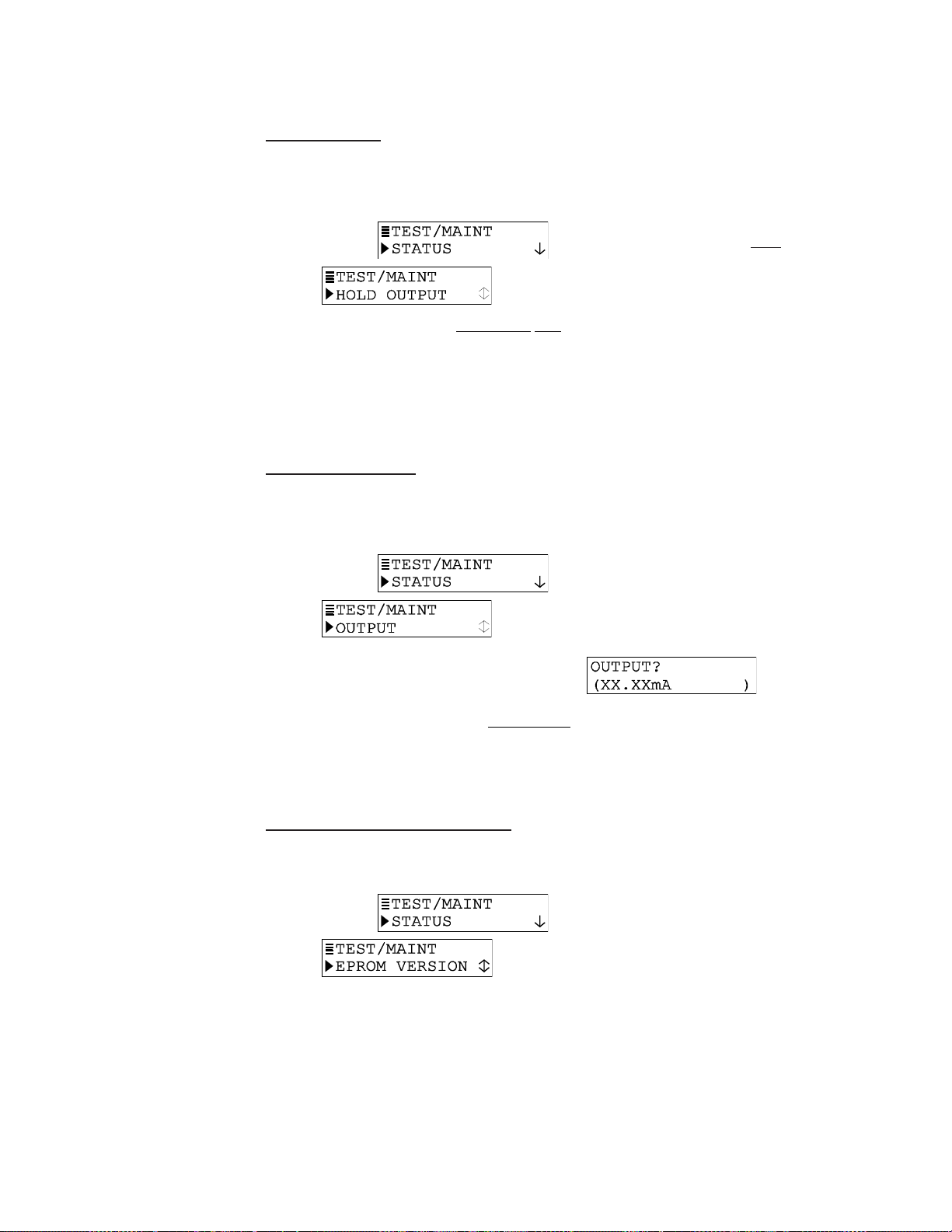
PAGE 51
9.2 HOLD OUTPUT9.2 HOLD OUTPUT
9.2 HOLD OUTPUT
9.2 HOLD OUTPUT9.2 HOLD OUTPUT
The HOLD OUTPUT function conveniently holds the analog output at its last measured value for
up to 30 minutes to suspend operation of any connected device.
1. With the
2. Press ENTER key to immediately hold the analog output (“HOLD OUTPUT: ENTER TO
RELEASE” screen appears, acknowledging hold is applied).
NOTE: If the keypad is not used within 30 minutes, the analog output will automatically
change back to its active state and the display will return to the MEASURE screen.
3. To release the hold at any time and return the analog output back to its “active” state,
press ENTER key (display returns to previous level of TEST/MAINT menu branch).
9.3 OUTPUT T9.3 OUTPUT T
9.3 OUTPUT T
9.3 OUTPUT T9.3 OUTPUT T
The OUTPUT function provides an analog output test signal of a desired mA value to confirm
operation of a connected device.
1. With the
2. Press ENTER key to display a screen like
est Signalest Signal
est Signal
est Signalest Signal
screen appears.
screen displayed, press
screen displayed, press
ØØ
Ø key once to display
ØØ
ØØ
Ø key until
ØØ
.
NOTE: The mA output test signal
3. Use arrow keys to adjust the displayed value to obtain the desired mA test signal.
4. To remove the output test signal and return to the previous level of the TEST/MAINT
menu branch, press ESC key or ENTER key.
9.4 Firmware (EPROM VERSION) Check9.4 Firmware (EPROM VERSION) Check
9.4 Firmware (EPROM VERSION) Check
9.4 Firmware (EPROM VERSION) Check9.4 Firmware (EPROM VERSION) Check
The EPROM VERSION function checks the version of firmware used in the transmitter.
1. With the
2. Press ENTER key to view the EPROM version screen.
3. To return to the previous level of the TEST/MAINT menu branch, press ESC key or
ENTER key.
is now active. Its value is shown on this screen.
screen displayed, press
screen appears.
ØØ
Ø key until
ØØ
Page 52
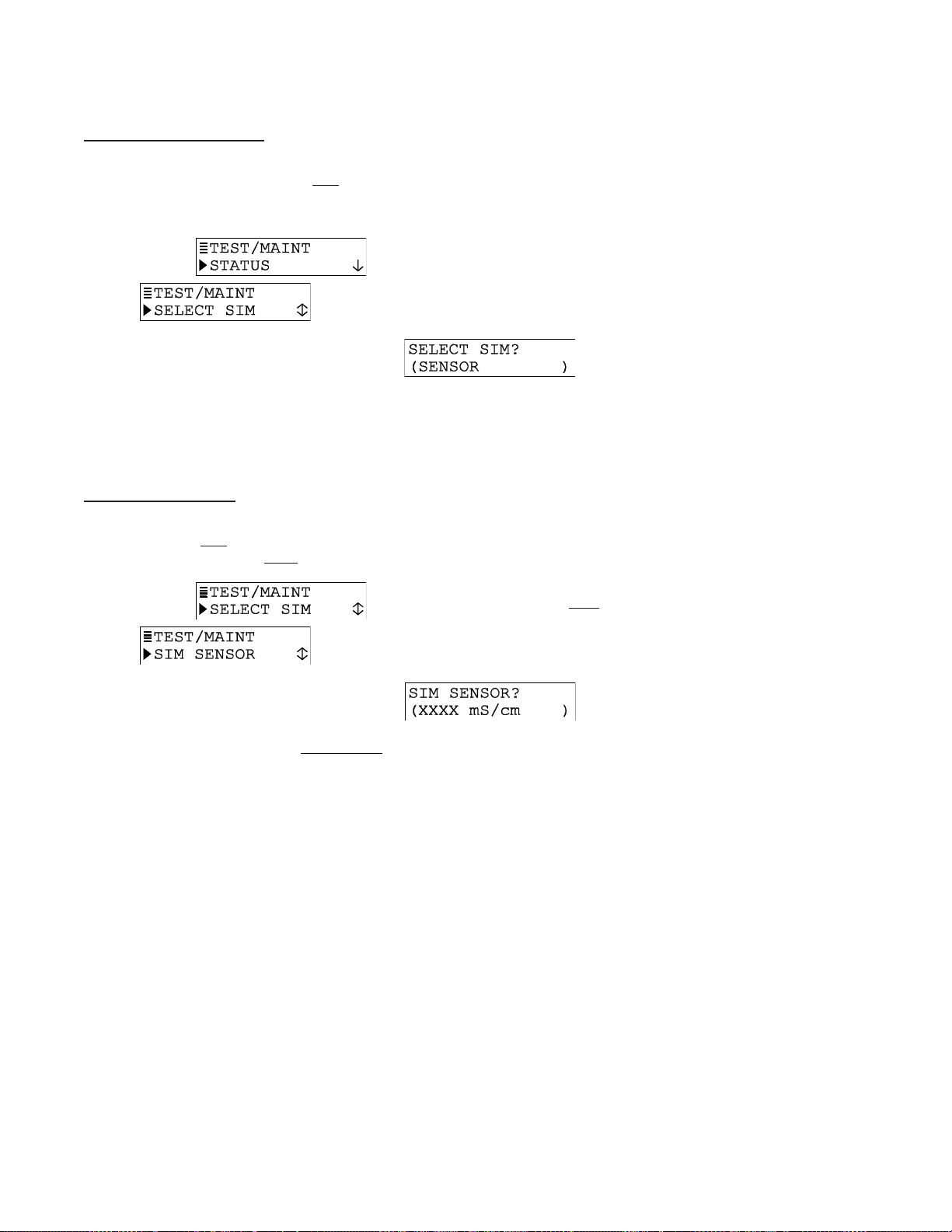
PAGE 52
9.5 SELECT SIM Measurment9.5 SELECT SIM Measurment
9.5 SELECT SIM Measurment
9.5 SELECT SIM Measurment9.5 SELECT SIM Measurment
The SELECT SIM function selects a type of simulated measurement. It is used in conjunction
with the SIM SENSOR function (Section 9.6) to simulate a measured value, making the analog
output respond accordingly.
1. With the
screen appears.
2. Press ENTER key to display a screen like
keys to select the type of simulated measurement, and press ENTER key to enter it:
screen displayed, press
ØØ
Ø
key until
ØØ
. Use
ØØ
Ø and
ØØ
××
×
××
• SENSOR: Selects simulated measurement to be the configured measurement
(conductivity, % concentration or TDS).
• TEMPERATURE: Selects simulated measurement to be temperature.
9.6 SIM SENSOR Setting9.6 SIM SENSOR Setting
9.6 SIM SENSOR Setting
9.6 SIM SENSOR Setting9.6 SIM SENSOR Setting
After selecting the type of simulated measurement (Section 9.5), use the SIM SENSOR function
to set the desired simulation value.
1. With the
.
2. Press ENTER key to display a screen like .
screen displayed, press
ØØ
Ø key once to display
ØØ
NOTE: The analog output signal is now active. It has a mA value that corresponds to the
measurement value shown on this screen.
3. Use arrow keys to adjust the displayed simulation value to the desired value.
4. To remove the simulated output and return to the previous level of the TEST/MAINT
menu branch, press ESC key or ENTER key.
Page 53
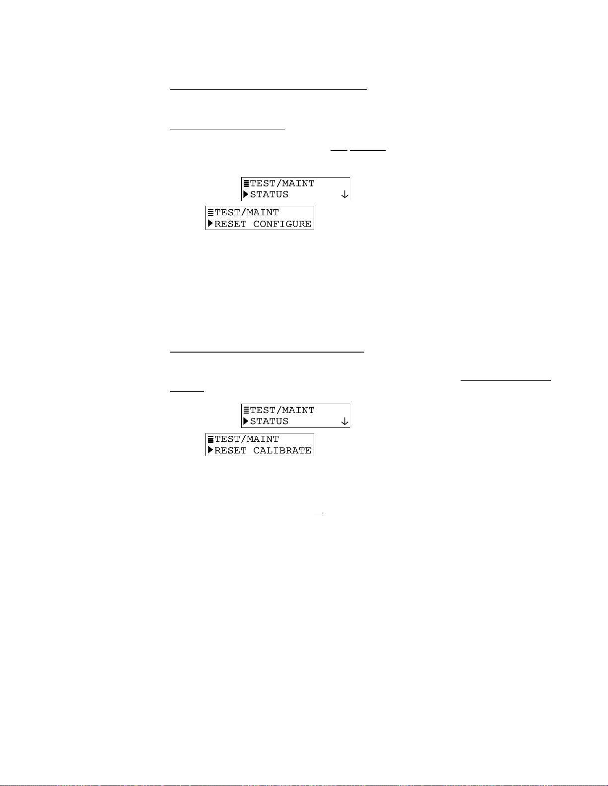
PAGE 53
9.7 RESET CONFIGURE V9.7 RESET CONFIGURE V
9.7 RESET CONFIGURE V
9.7 RESET CONFIGURE V9.7 RESET CONFIGURE V
The RESET CONFIGURE function resets stored configuration settings (all at the same time) —
but not calibration settings — to their factory-set defaults shown in TABLE D.
NOTE: Resetting configuration values also excludes the SELECT MEASURE function
(conductivity, % concentration or TDS) which remains as is until you change it.
1. With the
2. Press ENTER key to display the “RESET CONFIGURE: ARE YOU SURE?” screen,
asking if you really intend to perform this extreme action. (To abort this procedure,
press ESC key now.)
3. Press ENTER key to reset stored configuration settings — not calibration settings —
to factory defaults. The “RESET CONFIGURE: DONE” screen appears, acknowledging
that reset has occurred.
4. To return to the previous level of the TEST/MAINT menu branch, press ESC key or
ENTER key.
9.8 RESET CALIBRA9.8 RESET CALIBRA
9.8 RESET CALIBRA
9.8 RESET CALIBRA9.8 RESET CALIBRA
The RESET CALIBRATE function resets all stored calibration settings — but not configuration
settings — to factory-set defaults.
TE VTE V
TE V
TE VTE V
alues to Falues to F
alues to F
alues to Falues to F
alues to Falues to F
alues to F
alues to Falues to F
actory Defaultsactory Defaults
actory Defaults
actory Defaultsactory Defaults
screen displayed, press
screen appears..
actory Defaultsactory Defaults
actory Defaults
actory Defaultsactory Defaults
ØØ
Ø key until
ØØ
1. With the
screen appears.
2. Press ENTER key to display the “RESET CALIBRATE: ARE YOU SURE?” screen,
asking if you really intend to perform this extreme action. (To abort this procedure,
press ESC key now.)
3. Press ENTER key to reset all stored calibration settings — not configuration settings
— to factory defaults. The “RESET CALIBRATE: DONE” screen appears, acknowledging that reset has occurred.
4. To return to the previous level of the TEST/MAINT menu branch, press ESC key or
ENTER key.
screen displayed, press
ØØ
Ø key until
ØØ
Page 54

PAGE 54
Section 10 - TSection 10 - T
Section 10 - T
Section 10 - TSection 10 - T
10.1 K10.1 K
eeping the Teeping the T
10.1 K
eeping the T
10.1 K10.1 K
eeping the Teeping the T
Depending on application circumstances, periodically calibrate the transmitter to maintain
measurement accuracy.
Maintenance Tip! Upon startup, frequently check the system until operating
experience can determine the optimum time between calibrations that provides
acceptable measurement results.
Calibrate the transmitter using a method described in Section 8.3, 8.4 or 8.5. Calibrating with
old, contaminated or diluted reference solution may cause measure-ment errors. Do not reuse
reference solutions. Note that the value of a reference solution changes as its temperature
changes. Therefore, always allow the temperatures of the sensor and reference solution to
equalize while calibrating.
10.2 Avoiding Electrical Interference10.2 Avoiding Electrical Interference
10.2 Avoiding Electrical Interference
10.2 Avoiding Electrical Interference10.2 Avoiding Electrical Interference
Recommendation: Do not run sensor cable (and interconnect cable, if used) in
same conduit with AC or DC power.
Maintenance Tip! Excess cable should not be coiled near motors or other
equipment that may generate electrical or magnetic fields. Cut cables to proper
length during installation to avoid unnecessary inductive pickup (“electrical noise”
may interfere with the sensor signal).
roubleshootingroubleshooting
roubleshooting
roubleshootingroubleshooting
ransmitter Calibratedransmitter Calibrated
ransmitter Calibrated
ransmitter Calibratedransmitter Calibrated
When experiencing problems, try to determine the primary measurement system component
causing the problem (sensor, transmitter or interconnect cable, if used).
10.3 Checking Electrical Connections10.3 Checking Electrical Connections
10.3 Checking Electrical Connections
10.3 Checking Electrical Connections10.3 Checking Electrical Connections
1. Verify that adequate DC voltage exists at the appropriate transmitter TB1 terminals.
2. Check all transmitter wiring to ensure proper connections.
10.4 V10.4 V
erifying Sensor Operationerifying Sensor Operation
10.4 V
erifying Sensor Operation
10.4 V10.4 V
erifying Sensor Operationerifying Sensor Operation
To verify sensor operation, refer to the procedure in the troubleshooting section of the sensor
operating manual. Or replace the suspect sensor with a known new or working sensor and
perform calibration.
10.5 V10.5 V
erifying Terifying T
10.5 V
erifying T
10.5 V10.5 V
erifying Terifying T
1. After disconnecting DC power and the sensor from the transmitter, connect a 1000 ohm
resistor between Terminals 4 (red) and 5 (yellow) on TB2.
2. Connect a 100,000 ohm resistor between Terminals 1 (white) and 7 (green) on TB2.
3. Reconnect DC power to the transmitter.
4. Verify that the transmitter conductivity reading is between 5.00 and 50.00 mS/cm. Also,
verify that the temperature reading is between -10 and +10°C.
If these readings are achieved, the transmitter is operating properly, but the interconnect cable
(if used) may be faulty.
ransmitter Operationransmitter Operation
ransmitter Operation
ransmitter Operationransmitter Operation
Page 55
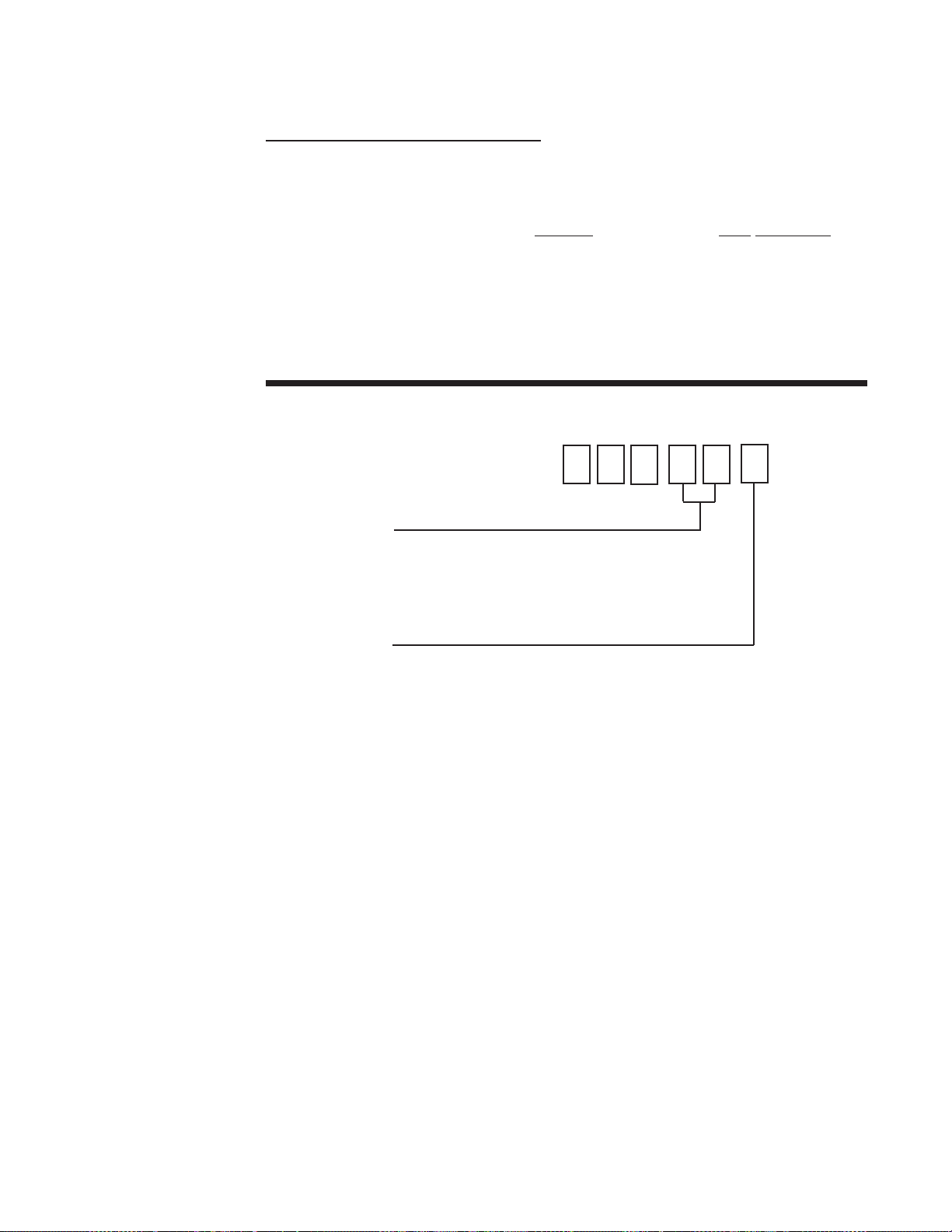
PAGE 55
10.6 V10.6 V
erifying Interconnect Cable Integrityerifying Interconnect Cable Integrity
10.6 V
erifying Interconnect Cable Integrity
10.6 V10.6 V
erifying Interconnect Cable Integrityerifying Interconnect Cable Integrity
1. Disconnect DC power from the transmitter. Reconnect the sensor directly to the
transmitter (purposely bypassing the interconnect cable and junction box, if used).
2. Place the sensor in a container of
3. Reconnect DC power to the transmitter.
4. Verify that the transmitter conductivity reading is between 150 and 350 mS/cm. If the
reading is achieved, the interconnect cable and/or junction box connections are
probably faulty. Use a digital multimeter to check the interconnect cable for shorted or
open wires.
Section 11 - Ordering MatrixSection 11 - Ordering Matrix
Section 11 - Ordering Matrix
Section 11 - Ordering MatrixSection 11 - Ordering Matrix
saturated salt water that is at room temperature.
D A 2 A
MOUNTING STYLE
01 Panel Mount Kit
(includes gasket, retainer plate and four screws)
02 Wall/pipe/integral mounting
(for integral mounting, sensor Wiring Style
option 2 required)
FIXED CHARACTER
A Fixed Character
Page 56

PAGE 56
Section 12 - WSection 12 - W
Section 12 - W
Section 12 - WSection 12 - W
These products are sold by The Anderson Instrument Company (Anderson) under the
warranties set forth in the following paragraphs. Such warranties are extended only with respect
to a purchase of these products, as new merchandise, directly from Anderson or from an
Anderson distributor, representative or reseller, and are extended only to the first buyer thereof
who purchases them other than for the purpose of resale.
Warranty
These products are warranted to be free from functional defects in materials and workmanship
at the time the products leave the Anderson factory and to conform at that time to the
specifications set forth in the relevant Anderson instruction manual or manuals, sheet or sheets,
for such products for a period of one year.
THERE ARE NO EXPRESSED OR IMPLIED WARRANTIES WHICH EXTEND BEYOND THE
WARRANTIES HEREIN AND ABOVE SET FORTH. ANDERSON MAKES NO WARRANTY OF
MERCHANTABILITY OR FITNESS FOR A PARTICULAR PURPOSE WITH RESPECT TO THE
PRODUCTS.
Limitations
Anderson shall not be liable for any incidental damages, consequential damages, special
damages, or any other damages, costs or expenses excepting only the cost or expense of repair
or replacement as described above.
arranty and Rarranty and R
arranty and R
arranty and Rarranty and R
eturn Statementeturn Statement
eturn Statement
eturn Statementeturn Statement
Products must be installed and maintained in accordance with Anderson instructions. Users are
responsible for the suitability of the products to their application. There is no warranty against
damage resulting from corrosion, misapplication, improper specifications or other operating
condition beyond our control. Claims against carriers for damage in transit must be filed by the
buyer.
This warranty is void if the purchaser uses non-factory approved replacement parts and supplies
or if the purchaser attempts to repair the product themselves or through a third party without
Anderson authorization.
Returns
Anderson’s sole and exclusive obligation and buyer’s sole and exclusive remedy under the
above warranty is limited to repairing or replacing (at Anderson’s option), free of charge, the
products which are reported in writing to Anderson at its main office indicated below.
Anderson is to be advised of return requests during normal business hours and such returns are
to include a statement of the observed deficiency. The buyer shall pre-pay shipping charges for
products returned and Anderson or its representative shall pay for the return of the products to
the buyer.
Approved returns should be sent to: ANDERSON INSTRUMENT COMPANY INC.
156 AURIESVILLE ROAD
FULTONVILLE, NY 12072 USA
ATT: REPAIR DEPARTMENT
 Loading...