


Instruction
Manual
Sanitary Wiring Head RTD's
& Temperature Transmitters
Anderson Instrument Co. Inc.
156 Auriesville Road
Fultonville, NY 12072
1-800-833-0081
Fax 518-922-8997
Instrument Model Number_________________________________
Instrument Serial Number ____________________________________
Form Number AIC2001
© June 1997
Revised: August 2022
Supersedes: April 2018

PAGE 2
This manual provides the installer with instructions on assembly, installation,
wiring, calibration, and troubleshooting of Anderson
Temperature Transmitters.
Table of Contents
Section 1 - Introduction
1.1 Description 3
1.2 Specications
RTD Elements 3
Wiring Head 4
Analog Transmitter Module 4
SMART Transmitter Module 5
Display Module 5
Section 2 - Assembly
2.1 Element/Wiring Head 6
2.2 Field Assembly/Replacement of Components 7
Section 3 - Installation and Wiring
Section 4 - Service
4.1 Calibration (Any 4-20mA Transmitter) 11
4.11 Calibration (SMART) 12
4.2 Troubleshooting 13
4.3 Replacement/Spare Parts 13
Appendices
A Anderson 100 ohm RTD DIN Curve 14
B Intrinsically Safe Requirements 15
C Mini Temperature Transmitter Control Drawing 16
D SMART Control Drawing 17
E Technical Notes 18
F Warranty and Return Statement 19
Figures
1 Wiring Head Orientation 6
2 Wiring Diagram : 4-20mA Transmitter
(Standard, Mini, and SMART Module) 8
3 Field Wireable Connector Assembly for Transmitter 8
4 Wiring Diagram : RTD (Single Element) 9
5 Wiring Diagram : RTD (Dual Element) 9
6 Single Cable Grip/Seal Assembly 9
7 Dual Module Housing Assembly 10
8 Dual Cable Grip/Seal Assembly 10
8, 9 & 10

Section 1 - Introduction
1.1 Description
The Anderson Temperature Sensor you have purchased has been specically designed for
critical measurement applications in sanitary uid processing environments. It combines allstainless steel construction with a eld replaceable element, providing a unique, "no-exposedthreads" package. The element is embedded in a metallic substrate in the probe tip which
provides extremely fast response characteristics. The probe is then completely epoxy sealed
for protection against moisture and vibration damage. The O-ring seal provided on the probe
is unique in the industry, and eliminates the exposed threads and tall prole common to most
industrial style transmitters.
Since this product line is modular in design, the specications are divided into the following
sections:
Elements (RTD's)
Wiring Head (includes Mini)
Analog Transmitter Module (includes (Mini)
Digital Display Module
1.2 Specifications
1.2.1 RTD ELEMENTS
General: Anderson SA and SW Series RTD elements are 100 ohm, 3-wire
sensors which conform to DIN standards (commonly referred to as the
"385 coefcient").
PAGE 3
Type: 3 wire, 100 ohm, DIN standard, single element standard.
Dual element optional with most ttings.
Coefcient: .00385 ohms/ohm/°C
Accuracy: Conforms to ASTM E1137-B and IEC-751B:
0.10% (0.26°C) at ice pt.
0.18% (0.66°C) at 100°C
0.21% (1.0°C) at 180°C
Probe Diameters: 1/4" for direct sanitary clamp styles (1"-4")
3/4" for heavy duty option with direct sanitary clamp styles
5/32" for direct sanitary clamp styles (1/2" & 3/4") Single Element Only.
Probe Lengths: Available in 1/4" increments (1-1/8" - 42"). For insertion lengths over 6"
Response: 2.5 to 3 seconds for 63% step change (for 1/4" dia. or less)
Span: 400°F (221°C) maximum
Low End: -50°F (-45°C) minimum
High End: 350°F (180°C) maximum
Material: 316 "L" stainless steel wettable parts
Surface Finish: 8 microinch Ra (SW series)
heavy duty option recommended.
25 microinch Ra (SA series)
32 microinch Ra (thermo-well ttings)
Fitting Styles: All standard sanitary clamp styles, including fractional clamps and mini thermowell styles; Refer to ordering matrix for details.
Standards: Designed and manufactured to sound engineering practices in
accordance with Article 3.3 of the PRD 97/23/EC.

PAGE 4
1.2.2 WIRING HEAD (SAME FOR "MINI" EXCEPT WHERE NOTED IN ITALICS)
General: The wiring head is designed to accept any type of RTD element, but
offers the cleanest package when coupled with Anderson "no exposed
thread" RTD's, which provide an O-ring seal against the housing. The
wiring head houses the analog transmitter module and optional digital
display.
Material: 304 Stainless Steel
Surface Finish: 32 microinch Ra max.
Dimensions: 3.15" O.D. X 2.75" L. (2.00" O.D. X 1.95" L.)
Penetrations: (2) at 1/2" - 14 NPT female; (1) centered in bottom plate; (1) in side
beneath cap rim.
Cable "Grip": NEMA 4X "Hubbell" style connector, optional Quick Disconnect
Receptacle (QDR) for transmitter.
Ratings: NEMA 4X; IP-66
1.2.3 ANALOG TRANSMITTER MODULE (SAME FOR "MINI" EXCEPT WHERE NOTED IN ITALICS)
General: The analog transmitter module is a one-piece sealed unit that can be
factory or eld installed, providing input and output terminations that
are easily accessible.
Input Type: 3-wire, 100 ohm, DIN standard curve (385 coefcient).
Output Type: 2-wire, 4-20 mA analog
Power Supply: 9 to 32 Volts d.c. loop power required (14-37 Volts d.c. with
optional display).
Accuracy: 0.1% of calibrated span (when operated at calibrated voltage),
linearized.
Power Supply Effect: Less than 0.0125% of full scale output per volt.
Minimum Span:
Maximum Span:
Minimum Low End:
Maximum Low End:
Minimum High End:
Maximum High End:
Wiring Connections:
Isolation:
Burn-Out:
Zero Adjustment:
50°F or °C
300°F, 180°C
0°F or °C
100°F or °C
50°F or °C
350°F, 250°C*
Screw terminals with #3 screws.
(removable screw terminal connectors that accept 30-14 AWG
conductors)
Non-isolated
Upscale (factory standard), downscale (consult factory)
"Pot" adjustable to ±25°F (±15°C) typical
Span Adjustment:
Agency Approvals
Hazardous Locations:
*250 °F, 121 °C for fitting code 088-000 and 089-000.
"Pot" adjustable over a ±25°F (±15°C) range minimum
(Mini Only) Meets UL requirements for Class 1, Div. 1&2; Groups
A-D for intrinsically safe apparatus when installed with barrier as
required in control drawing provided in manual.

PAGE 5
1.2.4 "SMART" TRANSMITTER MODULE
Input: 3 wire RTD, 100 ohm, DIN std. (.00385 ohms/ohm/°C).
Output: 4-20mA, linear with temperature; Digital output signal
superimposed on 4-20mA signal; "HART" compliant.
Isolation: Input/Output isolated to 500V rms (707V p-p).
Accuracy: ±0.1% of Upper Range Limit (URL); Includes non-repeat
ability, non-linearity, and hysteresis.
Stability: 0.1°C per 6 months
Maximum Span: 230°C
Minimum Span: 6:1 turndown (38°C)
Maximum Range: -50 to 180°C
Power Required: 14-40 VDC external loop power (unregulated)
Power Supply Effect: Less than 0.005 of span per Volt
Maximum Loop Resistance: (Supply Voltage - 14) x 40 = Ohms
Agency Approvals:
Electromagnetic Compatibility (EMC):
CE Compliant (for optional LCD only, display accuracy de rated up to 2% in 150 - 180 MHz and 230 - 350MHz, 10V/M
RF Field).
Hazardous Locations: Meets UL requirements for Class 1, Div. 1&2; when
installed with barrier as required in control
drawing provided.
Ambient Limits: -18 to 50°C
Ambient Effects: ±0.13°C per 28°C temperature change
Storage Temperature: -40 to 65°C
Humidity: 0 to 100% RH
Vibration Effects: Will withstand 2 g at 10-60 Hz
Failure Mode: Field Selectable, High or Low
Warranty: Two Years.
1.2.5 DISPLAY MODULE
General: The display module provides a local display of temperature or output
value in milliamps or percent. It mounts in the cap and is powered by
the loop power supply. It is designed to be easily added to any unit in
the eld or can be specied initially with any unit containing an analog
transmitter.
Digits: 3 - 1/2 digits
Digit Size: 0.5" High
Type: LCD (Liquid Crystal)
Mounting: Integral to cap; eld replaceable/upgradeable
Units of Display: 4-20mA; 0-100%; Degrees C (0-180.0°C max);
Degrees F (0-199.9°F max) factory set, or 0-300°F.
Accuracy: ±0.2% of scale
Loop Resistance: Adds less than 250 ohms

PAGE 6
Section 2 - Assembly
2.1 Element/Wiring Head
Anderson temperature sensors are generally ordered pre-assembled and calibrated. The RTD
sensor is connected to the wiring head and pre-wired to the RTD or transmitter module. Refer to
Section 3 for instructions on connecting field wiring to the unit.
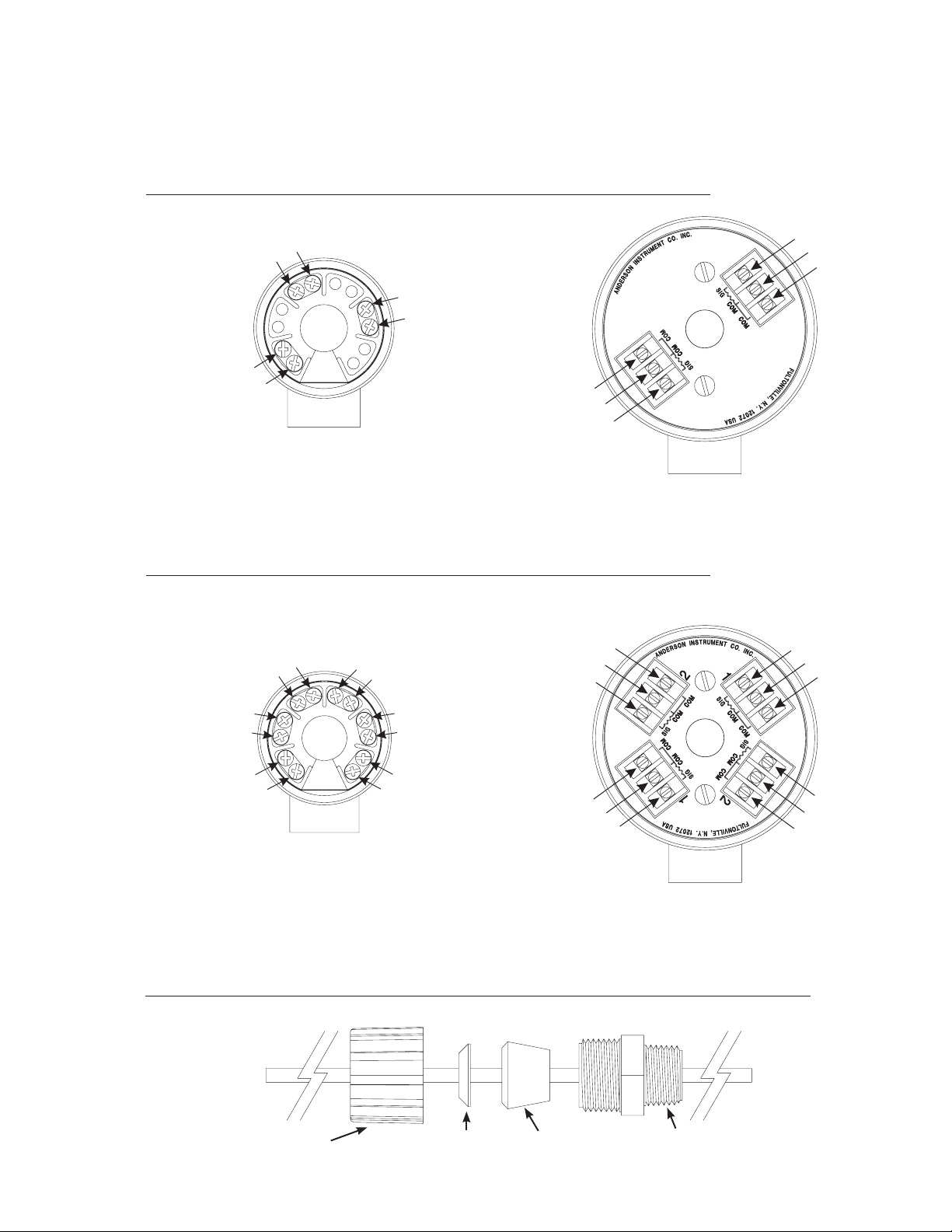
If ordered as separate components, the following diagram shows the options for orientation of the
wiring head.
Figure 1 - Wiring Head Orientation
Section 2 - Assembly
2.1 Element/Wiring Head
Anderson temperature sensors are generally ordered pre-assembled and calibrated. The RTD
sensor is connected to the wiring head and pre-wired to the RTD or transmitter module. Refer to
Section 3 for instructions on connecting eld wiring to the unit.
If ordered as separate components, the following diagram shows the options for orientation of the
wiring head.
Figure 1 - Wiring Head Orientation
Vertical Horizontal Mini RTD Head
Vertical Mount
O-ring
O-ring
O-ring

PAGE 7
2.2 Field Assembly/Replacement of Components
CAUTION: When replacing any components, or upgrading any module, rst interrupt power
to the unit.
Transmitter Module: Regardless of orientation, the transmitter module is always mounted in the
base of the wiring head, using the two screws supplied. The module should
be orientated as shown in the "Wiring Diagram". Tighten the screws snugly
with a medium size screwdriver. The mini transmitter module is permanently
installed in the mini wiring head and is not equipped with screws.
RTD Sensors: Sealed Cable RTD's are pre-wired and ready to install. Sensors for use
with wiring heads are shipped with factory supplied teon tape on the
threads. If removed, replace with a single wrap of teon tape to lubricate
the threads and prevent galling. Ensure o-ring (part# 36240N2019) is
installed prior to threading probe into housing. Remove the wiring head
cap and insert the RTD wires up through the center of the module (vertical
mount) and through the side penetration (horizontal mount). The best
orientation for an application will generally depend on whether a display
will be included. If so, the wiring head should be oriented to provide the best
viewing angle for the display. Hand tighten the sensor into the head and
then use a wrench to apply approximately 30 ft-lbs. of torque.
For Transmitter applications, connect the three RTD wires to terminals
labeled SIG, COM, and COM. The odd color (black or blue) wire connects
to SIG, and the two with the same color (white or yellow) connect one
each to the COM terminals. For RTD applications, wire each lead under a
separate terminal screw as shown in Figure 4 or 5.
Optional Display: If supplied, the digital display module should now be connected. Install
the Red wire to terminal DISP+ and the Black wire to DISP-. With the
display wired, now cut the factory installed jumper wire as shown on the
wiring plate, and in the wiring diagram. If the display is being retro-t into
an existing, blind transmitter, the cap must also be replaced with the cap
supplied with the display module.
The unit is now ready for connection to eld wiring.

PAGE 8
Section 3 - Installation and Wiring
Install the sensor into the process using the appropriate sanitary clamp and gasket, or by threading into a
mating thermowell. Orient the conduit connection for ease of connection to eld wiring before nal tightening.
Field wiring should be PVC coated, shielded, 22-24 AWG cable with at least two conductors for transmitters
and three for RTD's. Cable sheath OD 0.16 - 0.31". Trim the shield back so it cannot contact the stainless
steel head. (The shield wire should be connected to a single, clean ground terminal at the receiver or power
supply). Strip and tin the conductors. For Transmitters, connect the positive lead from the power supply to the
LOOP+ terminal and the other lead to LOOP-. The mini transmitter is provided with removable plug terminals
instead of terminal blocks to facilitate wiring. The plugs must be reinstalled in the transmitter after the eld
wires are connected to the plugs. See the wiring diagram below for details.
Figure 2 - Wiring Diagram : 4-20mA Transmitter, 4-20mA "Mini" Transmitter, and 4-20mA Smart Module
561010160F
100 - 300 °F
.
O
I
N
C
C
.
T
N
T
E
E
M
U
R
T
S
N
I
N
O
S
R
SPAN
E
D
N
A
561270160F
100 - 300 °F
ROZE
M
P
.
T
R
A
N
S
M
I
T
T
E
R
KEEP THE WATER OUT: Every precaution has been taken in designing these sensors to eliminate failures
due to internal moisture. The sensors are epoxy sealed and the circuit board is completely "potted". The
sensor and cap are both O-ring sealed to the housing. The only remaining pathway for moisture is via the
eld wiring penetration. If care is taken to insure this connection is watertight, you can expect literally years
of reliable service from the sensor. Flexible or rigid conduit can be utilized to protect eld wiring but it must be
installed in such a manner that water vapor cannot condense inside and nd it's way to the wiring head. This
requires careful sealing of each and every connection and junction box along the way back to the receiver.
With short, dedicated runs, this approach has proven effective. The longer the run, and the more connections,
the more chance for leaks.
Another option is to terminate the conduit just short of the wiring lead penetration and utilize a watertight
(NEMA 4X) style cable grip to seal against the cable. If ordered with pre-wired cable, a cable grip is supplied,
which is optimum for the 24 AWG cable supplied. If the cable is replaced, be sure to select one with a
diameter of .187" to .250".
Once the sensor is properly wired, replace the display and/or cap before powering the unit.
Figure 3 - Field Wireable Connector Assembly for Transmitter
Receptacle
P/N: 56623A0002
Red - Loop + or +
Black - Loop - or -
Retaining Ring
Connector End
Sleeve
Compression
Seal
Grommet
4-8mm (0.16-0.31") Cable Sheath Diameter
Ring
Pressing Screw
-2 included choose one to accommodate cable OD
Loop+(red) wire
Loop- (black) wire
Shield (clear or bare) wire
Pin 2 - Black
(-PWR)
DETAIL
Pin 1 - Red
(+PWR 9-30 VDC)
Field Wireable Connector (assembled)
P/N: 42119B0000 (without cable)
NOTE: Receptacle pins should be coated with USDA approved
dielectric grease to minimize possibility of corrosion.
For RTD applications, wire the two common (same color) wires to the terminals as shown.
RTD(White)
CABLE(White)
RTD(White)
CABLE(Red)
RTD(Black)
CABLE(Green)
RTD(Blue)
CABLE(Blue)
RTD(White)
CABLE(White)
RTD(Black)
CABLE(Green)
RTD(White)
CABLE(Red)
RTD(Yellow)
CABLE(Black)
RTD(Yellow)
CABLE(Brown)
RTD 1
RTD 2
RTD 1
Red/White
Green
Red/White
RTD 2
Yellow
Blue
Yellow
RTD 1
White
Black
White
RTD 2
Brown/Black
Blue
Brown/Black
RTD(Blue)
CABLE(Blue)
RTD(White)
CABLE(White)
RTD(Black)
CABLE(Green)
RTD(White)
CABLE(Red)
RTD(Yellow)
CABLE(Black)
RTD(Yellow)
CABLE(Brown)
RTD 1
RTD 2
Hubbell Connector
Dual Module Connector
Figure 4 - Wiring Diagram : RTD (Single Element)
Red/White
Red/White
Green
PAGE 9
RTD
Black
White
White
Mini Head
Figure 5 - Wiring Diagram : RTD (Dual Element)
Mini Head
RTD 1
Red/White
RTD 2
Yellow
Yellow
Blue
Red/White
Green
Standard Head
RTD 1
Black
White
White
RTD 2
Blue
Brown/Black
Brown/Black
Standard Head
Figure 6 - Single Cable Grip/Seal Assembly
P/N: 56047A0001
Compression Nut
Cable Grip
4-8mm (0.16-0.31") Cable Sheath Diameter
Compression Bushing
Connection

PAGE 10
P/N 33711G1909 (2X)
P/N 73509A0001 (2X)
CUTAWAY VIEW
Dual Module Connector
Figure 7 - Dual Module Housing Assembly
Remove the 2 screws that hold the upper module in place and remove the upper module from the housing
for wiring access to the lower module. (See Figure 4 and 5 for proper wiring conguration.)
P/N 73509A0001 (2X)
P/N 33711G1909 (2X)
Figure 8 - Dual Cable Grip/Seal Assembly
P/N: 42080D0001
Cable
Compression Nut
4-8mm (0.16-0.31") Cable Sheath Diameter
Compression Bushing
Connection

Section 4 - Service
4.1 Calibration (Any 4-20mA Transmitter)
RTD sensors are not adjustable but can be checked for proper operation using the procedure in
paragraph 3, section 4.2.
Anderson transmitters may be calibrated by making adjustments to the electronic circuitry via a ZERO
and a SPAN screw or "pot" contained within the sensor housing. If the transmitter is to be calibrated,
the following equipment will be required:
Well Agitated and Controlled Temperature Bath
Accurate Reference (lab thermometer)
12-40 VDC Power Supply
DC Milliammeter (accurate to .01 mA)
Jumper Leads
Jeweler's Screwdriver
Calculator
The output of a properly calibrated transmitter may be calculated by using the following formula:
mA output = 16 x (Known Value - Low End of Range) + 4
Transmitter Span
PAGE 11
The calibration procedure for Anderson Temperature and Transmitters is as follows:
1. Remove the conduit cap from the transmitter housing.
2. Wire up the transmitter as shown in the wiring diagram. Monitor the loop current with a
milliammeter.
3. Expose the sensor to a temperature near the low end of the range and allow the reading to
stabilize.
4. Calculate the proper reading using the formula above.
5. Adjust the zero pot (labeled ZERO) to cause the meter to read the proper reading.
6. Expose the sensor to a temperature near the high end of the range and allow the reading
to stabilize.
7. Again, calculate the correct reading.
8. Adjust the span pot (labeled SPAN) to cause the meter to read the calculated reading.
9. Repeat steps 3. through 8. until no further adjustment is necessary.
NOTE: For temperature transmitters with offset values less than zero, care must be taken
not to lose the (-) sign while performing the calculation of the proper reading.

PAGE 12
4.11 Calibration (SMART)
The Smart Module may be calibrated using the technique outlined in this manual for the analog
transmitter module. If utilizing a HART Communicator (HHT), follow the procedure below:
1.) Power the transmitter and immerse the probe in an ice bath for several minutes:
(Note: Consult our Technical Service Department if °C is NOT within the desired calibration
range for the unit being calibrated). The signal loop must have at least 250 ohms resistance for
the HHT function.
2.) Connect the "HART" HHT across the transmitter terminals, or the resistor in the loop.
3.) Press the I/O button on the HHT to turn it on, wait until communications are established
and the Process Value (PV) is displayed.
4.) If the Process Value is not within specication after stabilization:
a.) Move the right arrow to "Detailed Setup" and make the following selections:
"1" (Sensors)
"2" (Temp Sensor)
"3" (Sensor Trim)
"1" (Zero Trim)
"OK", "OK", "OK", "OK"
"HOME"
b.) Verify Process Value is now within specication
5.) Immerse the probe in a "hot" bath that is well agitated, within 10% of the upper range limit
of the transmitter.
6.) If the Process Value is not within specication after stabilization:
a.) Move the right arrow to "Detailed Setup" and make the following selections:
"1" (Sensors)
"2" (Temp Sensor)
"3" (Sensor Trim)
"2" (Upper Trim)
"OK", "OK", "OK", "OK"
"HOME"
b.) Verify the Process Value is now within specication.

4.2 Troubleshooting
In the event a problem arises with the temperature measurement being monitored by the sensor,
quickly check all wiring connections between the sensor and receiver. Be sure all connections
are still proper and tight.
For transmitters, if the receiver indicates a temperature that is in error when compared to other
instruments in the process, the milli-amp signal can be checked without removing the transmitter
from the process. Simply wire a milliammeter in series with the transmitter output and calculate
the proper signal for the known temperature, using the formula in the calibration section. If the
output agrees with the calculated value, the receiving instrument requires recalibration. If it is out
of tolerance (>.04mA error), the transmitter must be removed from the process and calibrated.
If the receiver indicates a failure condition such as an out-of-range value, and the wiring checks
out, the RTD signal wires can be disconnected from the transmitter module and checked for the
proper resistance. Use the table provided to determine the proper resistance for the temperature
being monitored, then check for that resistance between the black (blue) lead and each of the
white (yellow) leads. The resistance should read approximately the same as the value from
the chart (Appendix A) that corresponds with the test temperature. Also check for an "open" or
"short" circuit by measuring the resistance between each lead and the stainless steel probe. An
innite resistance indicates an "open" circuit and zero resistance indicates a "short" circuit. In the
case of a short circuit, the element needs to be replaced.
If RTD/Transmitters with insertion lengths of 1-1/4" or less output low, thermal insulation should
be packed around the RTD and its tting to minimize heat loss to ambient.
PAGE 13
If the RTD checks out and the output is still out-of-range, the transmitter module is suspect and
should be replaced. Replacement of the mini transmitter module requires replacement of the
wiring head since the transmitter and head are integral.
4.3 Replacement/Spare Parts
4.3.1 RTD ELEMENTS
Replacement or spare elements can be ordered by contacting our Customer Service Department with the serial number or model number of the original element.
4.3.2 TRANSMITTER MODULES
4-20mA modules can be ordered by the model number on the label, or simply by specifying the range and units required (e.g. 0-200°F). The 4-20mA mini transmitters can only be
ordered by the CT number identied on the side of the mini wiring head.
4.3.3 DIGITAL DISPLAY MODULES
As with the transmitter modules, order by range and units.
4.3.4 REPLACEMENT WIRING HEAD CAP
Standard Cap #5609300001
Standard Cap with Health Authority Seal Option #5609300003
Standard Cap, for use with Digital Display #44854A0002
Mini Cap #45009A0001
Mini Cap with Health Authority Seal Option #45009B0001

PAGE 14
Appendix A - Anderson 100 ohm RTD DIN Curve
0.00385 ohms/ ohm / °C
Degrees Fahrenheit
0
5
10
15
20
25
30
32
35
40
45
50
55
60
65
70
75
80
85
90
95
100
105
110
115
120
125
130
135
140
145
150
155
160
165
170
175
180
185
190
195
200
212
225
250
275
300
Degrees Celsius
-17.78
-15.00
-12.22
-9.44
-6.67
-3.89
-1.11
0.00
1.67
4.44
7.22
10.00
12.78
15.56
18.33
21.11
23.89
26.67
29.44
32.22
35.00
37.78
40.56
43.33
46.11
48.89
51.67
54.44
57.22
60.00
62.78
65.56
68.33
71.11
73.89
76.67
79.44
82.22
85.00
87.78
90.56
93.33
100.00
107.22
121.11
135.00
148.89
Ohms
93.04
94.12
95.21
96.31
97.39
98.48
99.57
100.00
100.65
101.73
102.82
103.90
104.98
106.07
107.15
108.22
109.31
110.38
111.45
112.53
113.61
114.68
115.76
116.83
117.90
118.97
120.04
121.11
122.17
123.24
124.31
125.37
126.44
127.50
128.56
129.62
130.68
131.74
132.80
133.86
134.91
135.97
138.50
141.24
146.48
151.70
156.90

Appendix B
Intrinsically Safe Requirements for 4-20mA Mini Transmitter
The following drawings (see Appendix C & D )illustrates additional requirements which must
be met in order to properly wire a 4-20mA mini transmitter to be recognized as Intrinsically
Safe.Specicationswhichmustbemetwhenchoosingabarrierstriphavebeenprovided.
NOTE: Anderson does not offer barrier strips for sale at this time - please see your local
electrical component supplier.
CAUTION:
ALL documented requirements MUST be met. A 4-20mA mini transmitter wired
without a barrier strip will not meet the guidelines for Intrinsically Safe applications.
PAGE 15

PAGE 16
Appendix C - Mini Temperature Transmitter
Control Drawing

Appendix D - SMART Control Drawing
PAGE 17

PAGE 18
WIRE RESISTANCE 4
4 WIRE RTD
WIRE RESISTANCE 1
RTD
2 WIRE RTD
WIRE RESISTANCE 2
WIRE RESISTANCE 1
WIRE RESISTANCE 3
WIRE RESISTANCE 2
RTD2
WIRE RESISTANCE 4
4 WIRE RTD
WIRE RESISTANCE 1
Appendix E - Technical Notes
RTD CONFIGURATIONS
There are 3 major RTD wiring schemes, two wire, three wire, and 4 wire.
Two Wire RTD
Figure 1 shows a two wire RTD conguration. A current source is applied
to one of the wires and the circuit ground is connected to the other. The
voltage generated is a function of the total resistance and the current (I)
going through it.
V = I x (RTD + Wire Resistance 1 + Wire Resistance 2)
Temperature = f(V)
It can be seen in the calculation that the length of the wires connecting to
the RTD affects the overall resistance, which will add an offset error to the
temperature measurement.
Three Wire RTD
A 3 wire RTD is used to negate the errors created by wire resistances
(Figure 2). This design requires two current sources(I1, I2), one applied
to wire 1 and one applied to wire 3. The sum of the two current sources
ow through wire 2.
The voltage at wire 1 will be:
VW1 = (I1 x WR1) + (I1 x RTD) + ((I1 + I2) x WR3)
The voltage at wire 3 will be:
VW3 = (I2 x WR3) + ((I1 + I2) x WR3)
This method requires that the resistance of wire 1 and its connections is
the same as wire 3 and its connections; VRTD is equal to VW3 - VW1. The
effect of wire and connection resistance has been canceled.
Therefore this is a good choice for sensors with longer but equal lead
lengths and good circuit connections.
2 WIRE RTD
WIRE RESISTANCE 1
RTD
WIRE RESISTANCE 2
3 WIRE RTD
WIRE RESISTANCE 1
RTD1
WIRE RESISTANCE 3
WIRE RESISTANCE 2
4 WIRE RTD
WIRE RESISTANCE 1
Four Wire RTD
The 4 wire RTD uses only 1 current source. A current is injected through
WR1, the RTD and WR2. WR4 and WR3 is connected to a very high
impedance differential amplier. Because there is no current owing
through WR3 and WR 4, there is no voltage drop across them and the
amplier inputs sees only the voltage directly across the RTD.
This method is not affected by the difference in wire and connection
resistances.
Therefore this is a good choice for sensors with non-equal lead lengths or
with connections resistances that could change over time.
WIRE RESISTANCE 4
RTD2
WIRE RESISTANCE 3
WIRE RESISTANCE 2

Appendix F - Warranty and Return Statement
These products are sold by the Anderson Instrument Company (Anderson) under the
warranties set forth in the following paragraphs. Such warranties are extended only with
respect to a purchase of these products, as new merchandise, directly from Anderson or from
an Anderson distributor, representative or re-seller, and are extended only to the rst buyer
thereof who purchases them other than for the purpose of resale.
Warranty
These products are warranted to be free from functional defects in materials and workmanship
at the time the products leave the Anderson factory and to conform at that time to the
specications set forth in the relevant Anderson instruction manual or manuals, sheet or sheets,
for such products for a period of one year.
THERE ARE NO EXPRESSED OR IMPLIED WARRANTIES WHICH EXTEND BEYOND THE
WARRANTIES HEREIN AND ABOVE SET FORTH. ANDERSON MAKES NO WARRANTY OF
MERCHANTABILITY OR FITNESS FOR A PARTICULAR PURPOSE WITH RESPECT TO THE
PRODUCTS.
PAGE 19
Limitations
Anderson shall not be liable for any incidental damages, consequential damages, special
damages, or any other damages, costs or expenses with the exception of the cost or expense
of repair or replacement as described above.
Products must be installed and maintained in accordance with Anderson instructions. Users
are responsible for the suitability of the products to their application. There is no warranty
against damage resulting from corrosion, misapplication, improper specications or other
operating conditions beyond our control. Claims against carriers for damage in transit must be
led by the buyer.
This warranty is void if the purchaser uses non-factory approved replacement parts and
supplies, or if the purchaser attempts to repair the product themselves, or through a third party,
without Anderson authorization.
Returns
Anderson’s sole and exclusive obligation and buyer’s sole and exclusive remedy under the
above warranty is limited to repairing or replacing (at Anderson’s option), free of charge, the
products which are reported in writing to Anderson at its main ofce indicated below.
Anderson is to be advised of return requests during normal business hours, and such returns
are to include a statement of the observed deciency. The buyer shall prepay shipping charges
for products returned, and Anderson, or its representative, shall pay for the return of the
products to the buyer.
Approved returns should be sent to:
ANDERSON INSTRUMENT COMPANY INC.
156 AURIESVILLE ROAD
FULTONVILLE, NY 12072 USA
ATTN: REPAIR DEPARTMENT

ANDERSON INSTRUMENT CO., INC • 156 AURIESVILLE RD. • FULTONVILLE, NY 12072 • USA • 800-833-0081 • FAX 518-922-8997
ANDERSON INSTRUMENT CO. LP • 400 BRITANNIA RD. EAST, UNIT 1 • MISSISSAUGA, ONTARIO L4Z 1X9 • CANADA • 905-568-1440 • FAX 905-568-1652
NEGELE MESSTECHNIK GmbH (A Division of Anderson) • RAIFFEISENWEG 7 • D-87743 EGG A. D. GÜNZ • GERMANY • +49 (0) 8333/9204-0 • FAX +49 (0) 8333/9204-49
MAIDA INTERNATIONAL (LATIN AMERICA & ASIA) 516-676-3079 • FAX 516-676-3199
www.anderson-negele.com
 Loading...