

Page 1
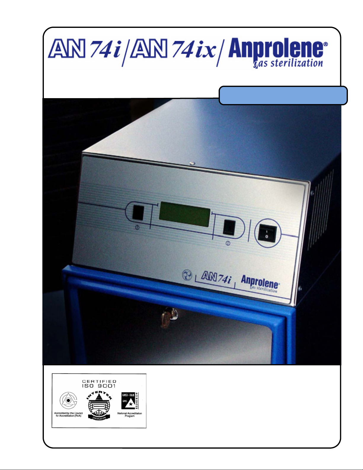
OWNER’S MANUAL
OWNER’S MANUAL
5/25/2005 11:38 AM
AN2000manual071603bgf
ETHYLENE OXIDE
STERILIZATION SYSTEM
Andersen Sterilizers, Inc. Health Science Park Haw River, NC 27258-8710
P/N7400 041105
Page 2
OWNER’S MANUAL
© Andersen Products Ltd
Owner’s Manual
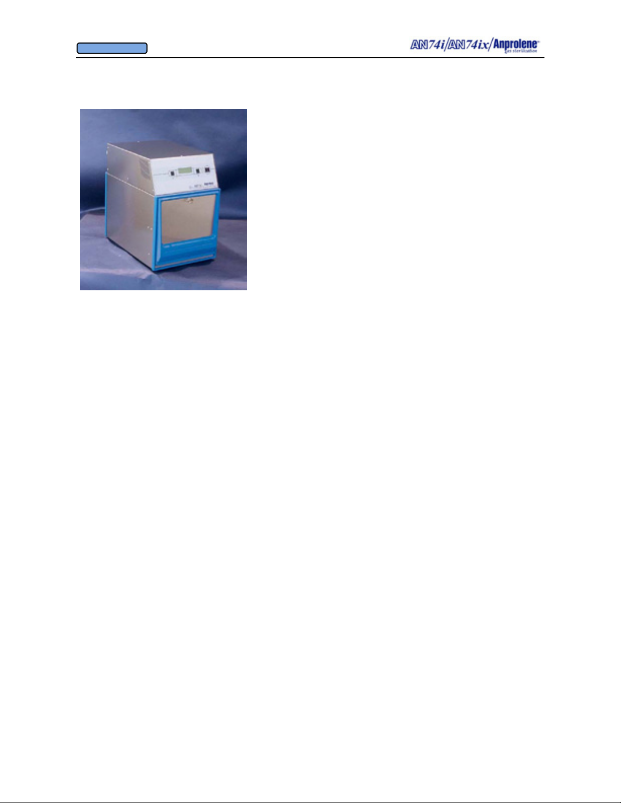
Congratulations on your purchase of an AN74i / AN74ix An-
prolene
been a leader in tabletop Ethylene Oxide sterilization. With the
installation of your sterilizer, you join thousands of healthcare
facilities worldwide using an Andersen Products’ sterilization system.
Please read the entire Owner’s Manual prior to installing
and using your new machine.
The Andersen Anprolene sterilizer uses less than 20% of the
amount of Ethylene Oxide gas of our nearest competitor (less than
18 grams). However, please note that Ethylene Oxide can be hazardous if not properly handled. Ethylene Oxide is also highly
flammable, so precautions should be taken to avoid improper installation or operation of the equipment near spark or open flame.
Knowing how to properly use the Anprolene system is important. With this in mind, we have included the
Operator Training and Education Section found in Section 4, beginning on page 17. Illustrated
instructions and information on humidification are included in the training section. In addition, you will
also find information concerning the Andersen Key Operator Certification Program. The Key Operator
Program covers all aspects of effective use of your Anprolene sterilizer and is offered free of charge for
the lifetime of the sterilizer. After reviewing the enclosed training material, please call 800-523-1276 or
336-376-3000 to schedule your exam. Outside the United States and Canada, please contact your local
distributor.
A list of suggested items that can be sterilized in the Anprolene sterilizer can be found on pages 28 and 29
of this manual. CAUTION: Food and drugs may not be sterilized because Ethylene Oxide may change
their chemical composition. If you are not certain about an item’s suitability for Ethylene Oxide sterilization, please contact an Andersen Customer Service Representative.
Section 6 of this manual covers Troubleshooting and Error Messages and begins on page 34.
Installation requirements and instructions are discussed in Appendices B through D, beginning on page 46.
Please call Customer Service at 800-523-1276 or 336-376-3000 for repair services. Outside the United
States and Canada, please contact your local distributor.
Instructions on preparation of products prior to sterilization appear in Section 1, beginning on page 5.
Accessories for use with your Anprolene sterilizer can be found in Section 5, beginning on page 30.
WARNING! If the Anprolene sterilizer is not installed and operated in the manner specified by
Andersen Products, the protection provided by the equipment may be seriously impaired.
DANGER! Ethylene Oxide is a Cancer and Reproductive hazard. Refer to MSDS on page 68 and EPA
approved labeling on all Anprolene refill kits for complete instructions and warnings.
In case of emergency, please call Andersen Products Customer Service at 336-376-3000 during regular
business hours (EST). After business hours, please contact 800-255-3924.
®
Sterilizer. For over 30 years, Andersen Products has
2
Page 3
OWNER’S MANUAL
© Andersen Products Ltd
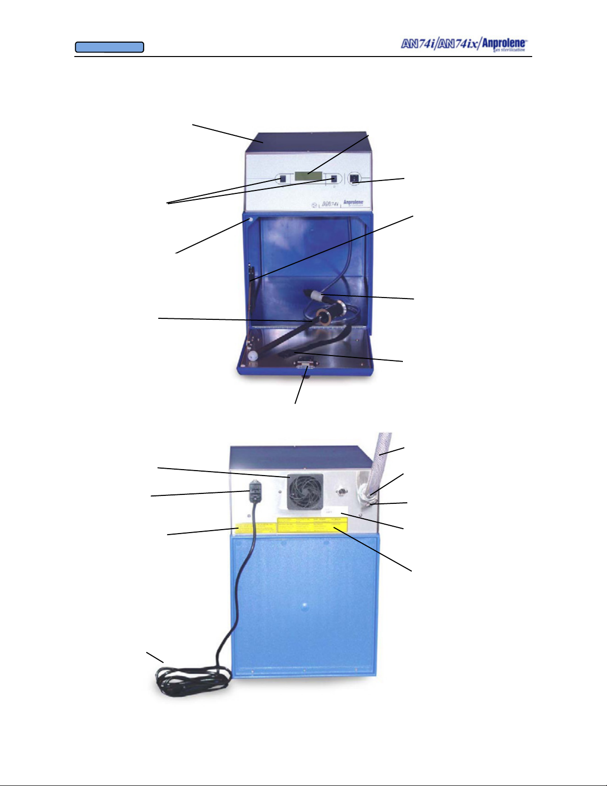
Overview of Features
Top Cabinet
Program Selection
Switches
Door Sensor
Purge Tube
Assembly
Back Lighted
Liquid Crystal Display
On/Off switch
Door Support
Quick Disconnect
Velcro® strap
Cooling Fan Guard
and
Removable Filter
Fuse Drawer
Replacement
Fuse
Specifications
Detachable
Grounded
Power Cord
Latching Door Lock
3/4” (1.91 cm) I.D.
Exhaust Tubing
Stainless Steel
Hose Clamp
Rear 3/4” I.D. Bulkhead
Exhaust Fitting & 90 Deg
Elbow
Underwriters Laboratories’ Approval Label
Electrical
Connection
Requirements
3
Page 4

OWNER’S MANUAL
© Andersen Products Ltd
TABLE OF CONTENTS
Introduction ............................................................................................................................2
Overview of Features..............................................................................................................3
Section 1 - Before You Begin.................................................................................................5
Section 2 - Diagrammatic Instructions for Normal Operation ...............................................8
Section 3 - Detailed Pictorial Instructions for Running the Sterilization Cycle...................12
Section 4 - Operator Training and Education.......................................................................17
Section 5 - Sundries for Use with Anprolene.......................................................................30
Section 6 - Warnings, Troubleshooting, Error Messages and Alarms .................................34
Section 7 - Maintenance ...................................................................................................... 42
Appendices
A - Technical Features.......................................................................................................... 44
B - Installation Requirements ............................................................................................... 46
C - Installation Instructions for New Anprolene Users ........................................................49
D - Installation Instructions for Current Anprolene Users ...................................................55
E - Flow Chart for Normal Operating Screen.......................................................................59
F - Material Safety Data Sheets............................................................................................68
G - AN74 i/ix Specifications ................................................................................................74
H - Equipment Ratings Summary and Replacement Parts List............................................77
I - Andersen One Year Limited Warranty............................................................................ 80
J - Useful Life of Sterilizer is Ten Years..............................................................................83
4
Page 5
OWNER’S MANUAL
© Andersen Products Ltd
SECTION 1
Before You Begin...
5
Page 6

OWNER’S MANUAL
© Andersen Products Ltd
SECTION 1
Before You Begin
There are a number of conditions that can affect the operation of your sterilizer. By paying
close attention to these details, you will greatly reduce the likelihood of problems.
1.1. Installation: Please make sure that your Anprolene sterilizer is installed correctly. Full installation instructions can be found in Appendix B, starting on page
46. Please call our Customer Service Department if you have installation questions
not covered in this section.
1.2. Environmental Factors: Your Anprolene sterilizer is designed to operate at
room temperature (68°F/20°C to 91°F/33°C ). Please pay close attention to the
following factors:
a. Temperature: Ethylene Oxide (EtO) is sensitive to temperature and
becomes less effective at lower temperatures. Make sure that the room
where the sterilizer is installed maintains a temperature between 68°F/20°C
and 91°F/33°C for the full duration of the sterilization cycle.
b. Humidity: Anprolene sterilization requires at least 35% relative humidity
(RH). In low humidity areas, or during the winter months when the
humidity level drops, an Andersen Humidichip
®
may be necessary to
achieve and/or maintain the proper humidity level in the sterilization liner
bag. Please refer to Section 4, beginning on page 17, for more information
on humidity and pre-humidification.
1.3. Preparing Items for Sterilization: Materials to be sterilized by all Ethylene
Oxide sterilizers, including Anprolene, must be meticulously cleaned and dried.
Coatings of dried proteins such as pus, blood or feces protect microorganisms and
slow the sterilization process. Precautions must always be taken before
sterilization with Anprolene. To prepare items for sterilization, please include the
following steps:
a. Disassemble - Anprolene is a highly diffusible gas sterilant; nevertheless,
occlusive caps, plugs and stylets must be removed from instruments so that
the gas can penetrate freely. Hollow bore needles and plastic or rubber tubing
must be open and free from stylets and plugs. Syringes must be packaged
with the plungers removed.
b. Wash - Scrub the disassembled instruments in detergent and water to the
most critical standard of cleanliness possible. We recommend the use of an
enzymatic cleaner such as Andersen Products’ AN2281 Surgical Instrument
Enzymatic Detergent, which may be used with most materials.
c. Dry - Water on instruments at the time of exposure to Anprolene may react
with the gas and reduce its effectiveness. Make sure that items to be sterilized are physically dry before wrapping and processing. Towel drying or
drain drying is sufficient. CAUTION: Do not use hot air to dry.
d. Wrap - All items to be sterilized must be wrapped in cloth, paper or plastic in
the manner conventional for steam sterilization, or in Andersen Seal and
®
Peel
Packaging.
6
Page 7

OWNER’S MANUAL
© Andersen Products Ltd
SECTION 1
Before You Begin
There are a number of conditions that can affect the operation of your sterilizer. By paying
close attention to these details, you will greatly reduce the likelihood of problems.
1.1. Installation: Please make sure that your Anprolene sterilizer is installed correctly. Full installation instructions can be found in Appendix B, starting on page
46. Please call our Customer Service Department if you have installation questions
not covered in this section.
1.2. Environmental Factors: Your Anprolene sterilizer is designed to operate at
room temperature (68°F/20°C to 91°F/33°C ). Please pay close attention to the
following factors:
a. Temperature: Ethylene Oxide (EtO) is sensitive to temperature and
becomes less effective at lower temperatures. Make sure that the room
where the sterilizer is installed maintains a temperature between 68°F/20°C
and 91°F/33°C for the full duration of the sterilization cycle.
b. Humidity: Anprolene sterilization requires at least 35% relative humidity
(RH). In low humidity areas, or during the winter months when the
humidity level drops, an Andersen Humidichip
®
may be necessary to
achieve and/or maintain the proper humidity level in the sterilization liner
bag. Please refer to Section 4, beginning on page 17, for more information
on humidity and pre-humidification.
1.3. Preparing Items for Sterilization: Materials to be sterilized by all Ethylene
Oxide sterilizers, including Anprolene, must be meticulously cleaned and dried.
Coatings of dried proteins such as pus, blood or feces protect microorganisms and
slow the sterilization process. Precautions must always be taken before
sterilization with Anprolene. To prepare items for sterilization, please include the
following steps:
a. Disassemble - Anprolene is a highly diffusible gas sterilant; nevertheless,
occlusive caps, plugs and stylets must be removed from instruments so that
the gas can penetrate freely. Hollow bore needles and plastic or rubber tubing
must be open and free from stylets and plugs. Syringes must be packaged
with the plungers removed.
b. Wash - Scrub the disassembled instruments in detergent and water to the
most critical standard of cleanliness possible. We recommend the use of an
enzymatic cleaner such as Andersen Products’ AN2281 Surgical Instrument
Enzymatic Detergent, which may be used with most materials.
c. Dry - Water on instruments at the time of exposure to Anprolene may react
with the gas and reduce its effectiveness. Make sure that items to be sterilized are physically dry before wrapping and processing. Towel drying or
drain drying is sufficient. CAUTION: Do not use hot air to dry.
d. Wrap - All items to be sterilized must be wrapped in cloth, paper or plastic in
the manner conventional for steam sterilization, or in Andersen Seal and
®
Peel
Packaging.
7
Page 8
OWNER’S MANUAL
© Andersen Products Ltd
SECTION 2
Diagrammatic Instructions
for Normal Operation
8
Page 9
OWNER’S MANUAL
© Andersen Products Ltd
SECTION 2
Diagrammatic Instructions for Normal Operation
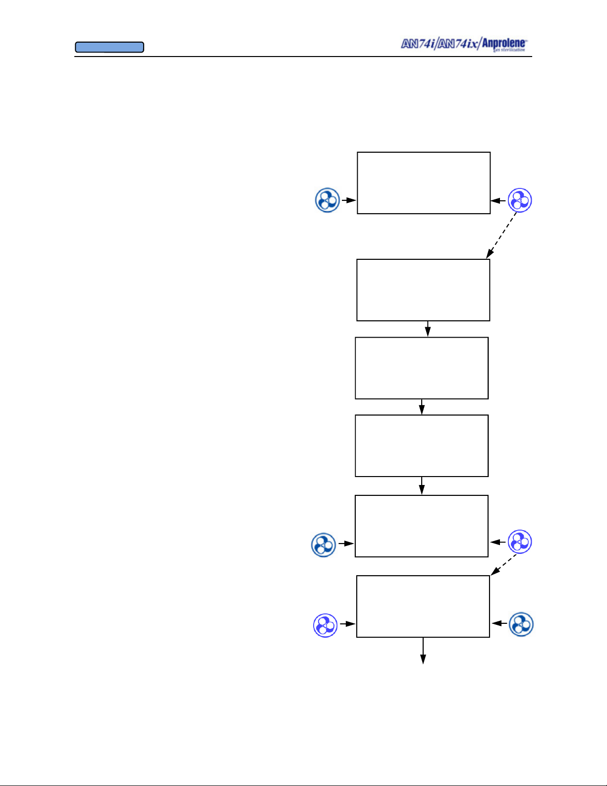
Turn on the sterilizer by pressing the on-off switch on
the back right side of the top cabinet.
The Liquid Crystal Display will illuminate. The initial
startup and standby screen is shown to the right.
To load the sterilizer and commence a sterilization
cycle, press the button immediately to the right of the
word START.
If an abator is attached to the machine, the number of
cycles remaining for the abator cartridge will be displayed. A new abator cartridge may be used for a
maximum of 250 sterilization cycles.
The display will indicate that the sterilizer has
performed a self test on the cabinet ventilation pump
and ventilation switch. The version of the computer
software is shown (VER 4.04). In addition, the total
number of hours that the ventilation pump has been
operating is shown (35 PUMP HOURS). This information is used to determine when preventive maintenance should be performed. (See Section 7). The
cooling fan blade speed is displayed as a percentage of
nominal operating speed (FAN 97% RPM).
Once the self test of the cabinet ventilation pump has
been successfully completed, the display will show the
instructions for loading the sterilizer. After the sterilization bag has been secured to the purge tube bobbin
via the Velcro strap, press the button to the right of the
word PURGE to evacuate air from the sterilization
bag.
The display will show the initial 1 minute, 30 second
initial purge is in progress. To stop the cycle and return to the standby screen, press the button to the left
of the word EXIT.
AN74 I
ANPROLENE STERILIZER
START
When START is pressed
250 ABATOR CYCLES
REMAINING
SELF TEST
VER 4.04
35 PUMP HOURS
FAN 97 % RPM
SELF TEST
OK
35 PUMP HOURS
FAN 97 % RPM
LOAD STERILIZER BAG
CLOSE BAG OVER TUBE
PURGE BAG
EXIT PURGE
When PURGE pressed
INITIAL PURGE
00:01:30 REMAINING
EXIT
Continued on next page
9
Page 10
OWNER’S MANUAL
© Andersen Products Ltd
Diagrammatic Instructions for Normal Operation, continued
Continued from previous page
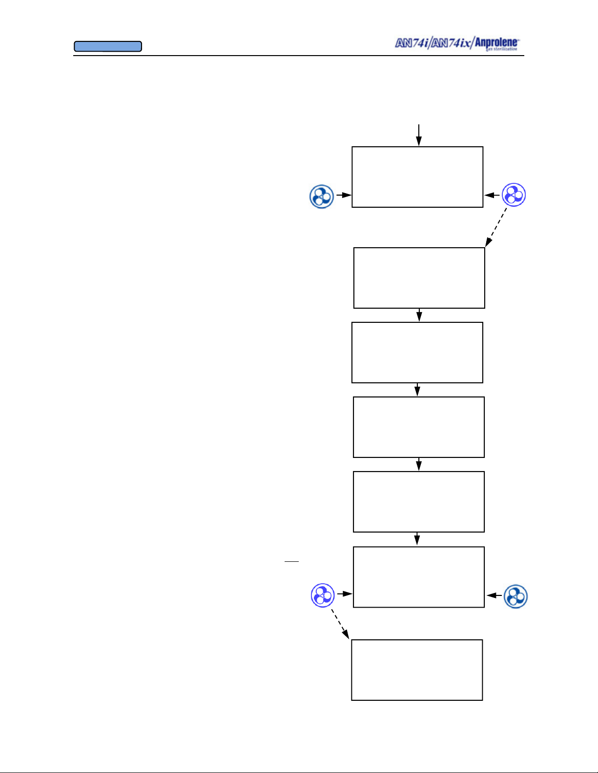
After the initial purge, the screen to the right will appear.
If the operator breaks the ampoule and closes the door
without selecting a cycle length, the sterilizer will beep
after 5 seconds to remind the operator to select the appropriate cycle length. The operator should break the Anprolene ampoule, close the sterilizer door, remove the key,
and select the desired cycle length.
Once the sterilization cycle has been initiated, the display
will show the cycle length chosen and the time remaining
in the sterilization cycle.
At the end of the sterilization cycle, the unit will begin a 2
hour sterilization liner bag ventilation (purge) cycle to
remove the residual Ethylene Oxide. The display will
show the time remaining in the purge cycle. During this
time the purge pump and cabinet ventilation pumps will
run alternating two minute cycles.
At the end of the 2 hour liner bag ventilation (purge) cycle,
the machine will beep once and instruct the user to
UNLOAD STERILIZER, signifying the end of the cycle.
The sterilizer may now be safely unloaded.
Note - Additional Aeration Option:
The ventilation pump and purge pump continue running
alternating two minute cycles until the door is opened and
the EXIT button is pressed. If needed, items may be left
in the machine for further aeration after the cycle has
ended by simply leaving the items inside the sterilizer.
The count-up timer indicates the additional aeration time.
Once the cycle has been concluded by opening the door
and pressing the EXIT button, both pumps will stop running and the sterilizer will return to the standby screen.
BREAK AMPOULE
CLOSE & LOCK DOOR
SELECT CYCLE LENGTH
24 HOUR 12 HOUR
When 12 hour cycle length
selected
12 HOUR CYCLE
STERILIZING
11:24:15 REMAINING
12 HOUR CYCLE
STERILIZING
11:24:15 REMAINING
VENTILATING BAG
01:59:55 REMAINING
UNLOAD STERILIZER
00:08:54
EXIT
UNLOAD STERILIZER
01:29:30
EXIT
When EXIT pressed
AN74 I
ANPROLENE STERILIZER
START
10
Page 11
OWNER’S MANUAL
© Andersen Products Ltd
Diagrammatic Abator Instructions:
Installing Optional New Abator Cartridge, Resetting Counter
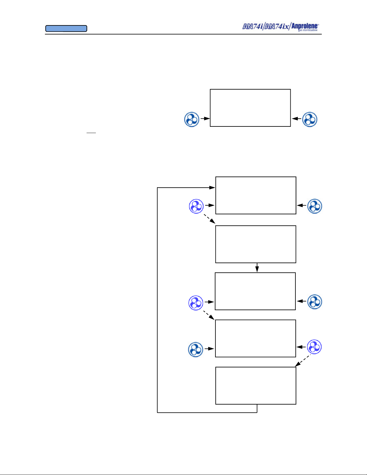
When the Abator cartridge has been used completely
(250 sterilization cycles), the screen will display
ABATOR CARTRIDGE EXPIRED and the alarm will
sound.
Additional cycles may be completed by bypassing the
screen. This is not
should be changed prior to starting a new cycle.
Once a new cartridge is installed, the
counter must be reset.
To reset the counter:
1. Hold the left button continuously for
more than 3 seconds
2. Press ABATOR button
3. Answer YES to the question:
INSTALL NEW ABATOR
CARTRIDGE
recommended. The cartridge
When
left button
pressed and held
for more than 3
seconds.
ABATOR CARTRIDGE
EXPIRED
EXIT BYPASS
AN74 I
ANPROLENE STERILIZER
PARAMETERS START
DIAGNOSTICS
ABATOR ATTACHED
PRESS ABATOR TO
INSTALL CARTRIDGE,
OTHERWISE PRESS DIAG
ABATOR DIAG
INSTALL NEW
ABATOR CARTRIDGE
NO YES
CARTRIDGE COUNTER
RESET TO 250
11
Page 12
OWNER’S MANUAL
© Andersen Products Ltd
SECTION 3
Detailed Pictorial Instructions
for Running a Sterilization Cycle
12
Page 13
OWNER’S MANUAL
© Andersen Products Ltd
SECTION 3
Detailed Pictorial Instructions for Running the Sterilization Cycle
Once the items to be sterilized have been disassembled, cleaned, dried and wrapped, the sterilization cycle can proceed.
3.1 Prior to loading the sterilizer: (1) Turn the power ON by pressing the right side of the
black power switch located on the back right corner of the machine. This will cause the initial
screen to appear. (2) Press the button to the right of START on the display screen to initiate
the self test.
AN74 I
ANPROLENE STERILIZER
START
Upon successful completion of the self test, the following LOAD screen will be displayed:
LOAD STERILIZER BAG
CLOSE BAG OVER TUBE
PURGE BAG
EXIT PURGE
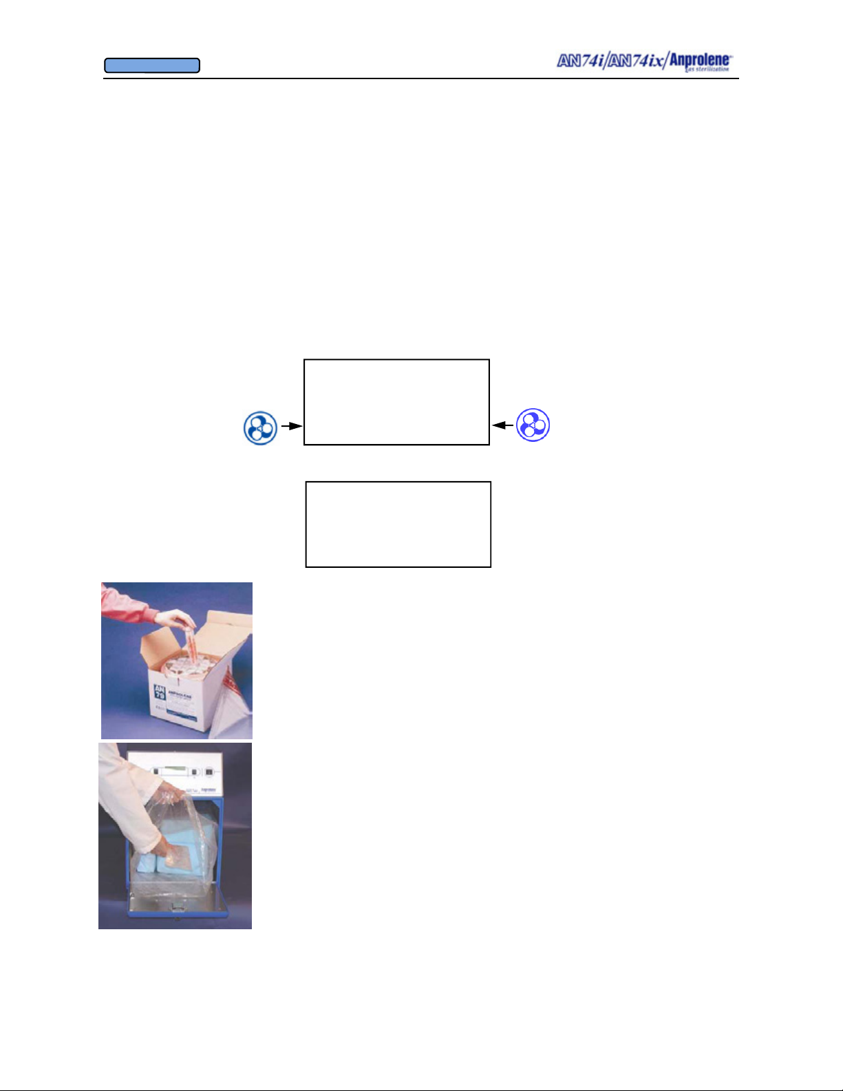
3.2. Preparation and loading of the sterilization liner bag:
a. Remove a sterilization liner bag from the refill kit and place it
inside the sterilizer cabinet with the open end facing you.
b. Place the wrapped items for sterilization inside of the steriliza-
tion liner bag.
c. Unroll the gas release bag containing the gas ampoule.
d. Without opening the gas release bag, gently move the ampoule
to the center of the gas release bag.
e. Place the gas release bag on top of the wrapped items so that you
can easily manipulate it through the wall of the bag after the
sterilization liner bag has been closed. Do not break the am-
poule at this time.
f. Place appropriate indicators inside of the sterilization liner bag.
(See Section 5 for more information concerning sterility indicators.)
13
Page 14
OWNER’S MANUAL
© Andersen Products Ltd
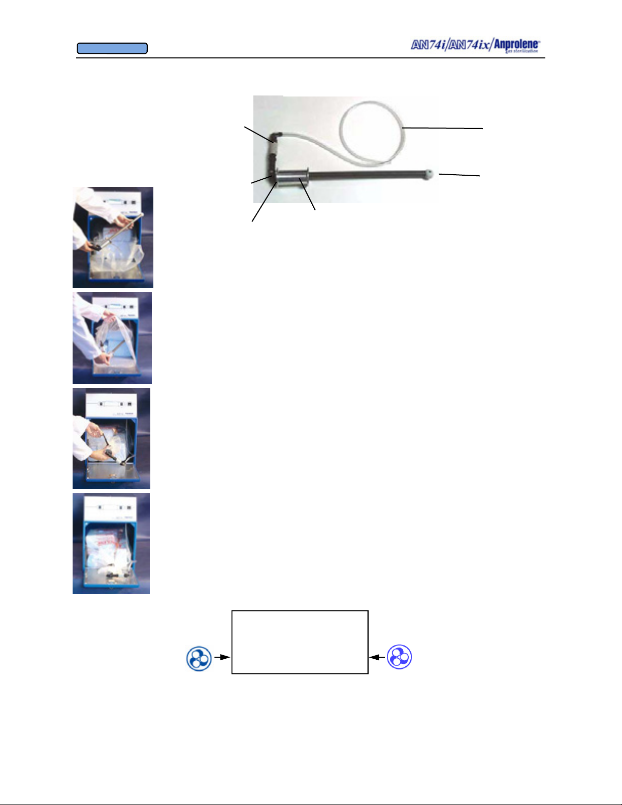
Quick Release
Connector
(Female end)
Quick Release
Connector
(Male end)
One-way Check valve
PURGE TUBE ASSEMBLY
Neck. Wrap the sterilization bag around aluminum
bobbin and secure with the Velcro strap
Purge tube,
this end is
connected to
upper cabinet.
End Goes
Into Liner
Bag
3.3. Insert the purge tube into the sterilization liner bag with the plastic
ball towards the rear of the bag and the neck towards the opening. Then,
gather the open end of the sterilization liner bag around the aluminum
neck of the purge tube, taking care to ensure you have left no openings.
3.4. Slip the black Velcro® strap around the outside of the sterilization
liner bag and thread the pointed end of the strap through the square black
loop. Pull the Velcro strap firmly and then wind it back around the exposed surface of the strap. Make sure that the Velcro strap is secure
and provides an airtight seal between the aluminum neck of the
purge tube and sterilization liner bag.
3.4.a. This is how the secured sterilization liner bag and purge
tube should appear.
3.5. If the purge tube has been disconnected from the sterilizer by means
of the quick release, simply reattach it by pressing the male and female
ends together until they click.
3.6. With the cabinet door open, press the PURGE button.
LOAD STERILIZER BAG
CLOSE BAG OVER TUBE
PURGE BAG
EXIT PURGE
14
Page 15
OWNER’S MANUAL
© Andersen Products Ltd
INITIAL PURGE
00:01:30 REMAINING
EXIT
3.8. After the initial purge has been completed (timer to 00:00:00), the display instructs the
operator to: (1) break the ampoule by manipulating the ampoule gas release bag through the
wall of the sterilization liner bag, (2) close the door, and (3) lock the door and remove the key.
3.9. Select the length of the sterilization cycle. For most items, the 12 HOUR cycle will be
adequate.
BREAK AMPOULE
CLOSE & LOCK DOOR
SELECT CYCLE LENGTH
24 HOUR 12 HOUR
3.10. When sterilizing lengths of tubing greater than 3 feet (91.5 cm) or loads containing gas
absorbent materials, the extended length 24 hour cycle should be used. Large volumes of gas
absorbent materials (rubber and plastic) also require the use of an additional Anprolene
ampoule and the extended 24 hour cycle. To operate the sterilizer using the extended 24 hour
cycle, press the button to the left of 24 HOUR. The display will then show STERILIZING
24:00:00 REMAINING.
24 HOUR CYCLE
STERILIZING
24:00:00 REMAINING
3.11. The sterilization cycle will then begin. Note: After the ampoule is activated and the
door is closed, if the operator does not select a cycle length within 5 seconds, a continuous
alarm will sound to remind the operator to select the appropriate cycle time.
12 HOUR CYCLE
STERILIZING
11:24:15 REMAINING
3.12. At the end of the 12 (or 24) hour cycle, the cabinet ventilation pump will stop and the
purge pump will run for two minutes, flushing Ethylene Oxide from the sterilization liner bag.
Then the purge pump will stop while the cabinet ventilation pump runs for two minutes. This
alternating cycling of the purge and cabinet ventilation pumps will continue for a period of
two hours. This will be displayed as shown below and will count down to 00:00:00.
VENTILATING BAG
01:59:59 REMAINING
15
Page 16
OWNER’S MANUAL
© Andersen Products Ltd
3.13. At the end of the two hour ventilation cycle, the following screen will appear,
notifying the operator that the sterilizer may be unloaded.
UNLOAD STERILIZER
EXIT
3.14. If the operator does not unload the sterilization liner bag at the end of the two hour
ventilation cycle, the purge pump and the cabinet ventilation pump continue to alternate on a
two minute cycle to flush the sterilization liner bag and cabinet indefinitely until the door is
opened and the EXIT button is pressed This feature may be used for Additional Aeration.
Refer to page 45.
UNLOAD STERILIZER
EXIT
3.15. If the operator opens the door after the two hour purge cycle is complete and presses
EXIT , both pumps will stop and the program will automatically return the sterilizer to the
start screen.
AN74 I
ANPROLENE STERILIZER
START
3.16. To unload the sterilizer, open the door and remove the Velcro® strap from around the
neck of the purge tube. Remove the purge tube from the sterilization liner bag. Unload the
wrapped items from the sterilization liner bag and place them on a shelf in a well-ventilated
room that has a minimum of 10 air changes per hour of fresh makeup air.
3.17. Gas absorbent materials such as rubber or plastic must be aerated in their individual
packages for at least 24 additional hours before they are used.
3.18. The used gas release bag ampoule and sterilization liner bag may be disposed of in
ordinary rubbish. Never reuse sterilization liner bags.
16
Page 17
OWNER’S MANUAL
© Andersen Products Ltd
SECTION 4
Operator Training and Education
17
Page 18

OWNER’S MANUAL
© Andersen Products Ltd
SECTION 4
Operator Training and Education
♦
Ethylene Oxide sterilization procedures must be supervised by personnel trained and
well informed in the safe use of such sterilant materials.
♦ Personnel working with ethylene oxide must have had comprehensive instruction in the
process. This instruction must cover the relevant health hazards (See MSDS on page 68),
relevant national regulations (e.g. OSHA regulation 29 CFR Part No. 1910 Standard No.
1910.1047), methods for safe use and methods to detect escape of sterilant material (e.g.
AN 93 Airscan Badges)
♦ Regular in-service programs relating to the process must be conducted and an attendance
record and evidence of understanding must be kept for each employee (e.g. Andersen
Key Operators Test)
.
18
Page 19

OWNER’S MANUAL
© Andersen Products Ltd
4.1 Humidity and Pre-humidification
4.2 Abridged Illustrated Instructions
4.3 Key Operator Study Guide
4.1. Humidity and Pre-humidification.
It has been demonstrated repeatedly that some microorganisms are made very resistant to
Ethylene Oxide sterilization systems by desiccation, which is exposure to very low relative
humidity.
As a result, humidity is a very important part of the Ethylene Oxide sterilization cycle. Items
that can be washed in water and towel or air dried will not need pre-humidification.
Items that may be damaged by immersion in water or a sterilization load that contains a large
amount of material that will absorb water (dry paper and cloth) will need pre-humidification.
Process for Pre-Humidification Using an Anprolene Sterilization Liner Bag
a. Items that cannot be immersed in water should be disassembled and wrapped in
the usual way.
b. Place the prepared items along with a Humidichip
®
bag. Using a twist tie or Velcro
strap, securely close the neck of the bag.
c. Leave the items in the bag for a minimum of four hours at a temperature of
68°F /20°C or higher
. Pre-humidification may take place outside the sterilizer
®
inside a sterilization liner
cabinet. Take caution not to rip or puncture the sterilization liner bag.
During the sterilization cycle, use a Humidichip to ensure a minimum of 35% Relative Humidity inside the sterilization liner bag. Items that did not need pre-humidification can be
added to the sterilization liner bag, along with the appropriate controls such as Dosimeter
®
Steritest
sterilization liner bag, use a new liner bag for the sterilization cycle.
, or other Biological Indicators. If there is any question as to the integrity of the
®
,
19
Page 20
OWNER’S MANUAL
© Andersen Products Ltd
4.2 ABRIDGED ILLUSTRATED INSTRUCTIONS
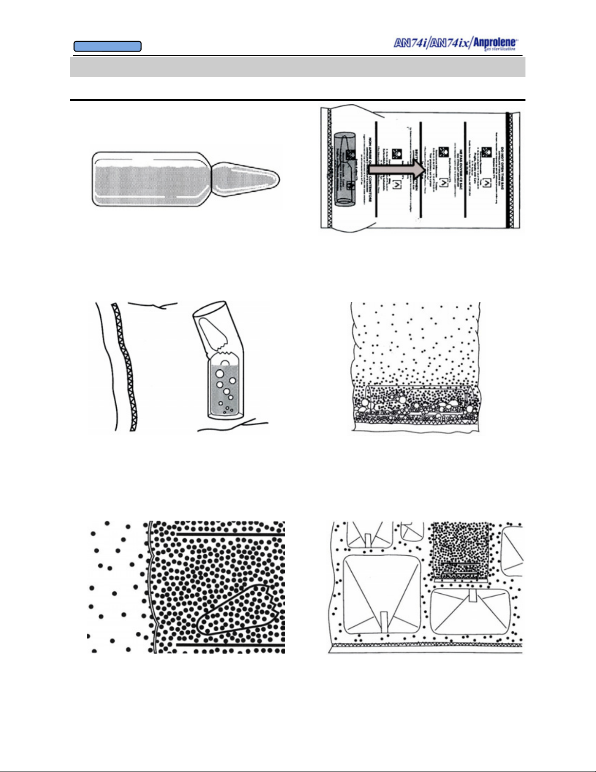
HOW ANPROLENE WORKS
1. The glass ampoule contains liquid Ethylene Oxide (EtO) and
an inert solid stabilizer. The ampoule is scored at the neck for
easy opening.
3. After the gas release bag is placed inside of the sterilization
liner bag and it is secured to the purge bobbin, the sterilization
bag is then vacuumed down. To release pure EtO gas, manually
snap off the top of the ampoule by manipulating it through the
walls of the sterilization liner bag. The plastic/fabric shield
prevents the broken glass of the opened ampoule from puncturing the gas-release bag.
2. A plastic/fabric break shield surrounds the ampoule.
The ampoule and shield are sealed inside a plastic gasrelease bag, which should never be opened.
IMPORTANT! Push the ampoule to the center of the
gas release bag before activating
4. The liquid EtO then boils, releasing 100% EtO gas
within the gas-release bag, leaving residual deposits of
the previously dissolved inert solid stabilizer.
5. Since the walls of the gas-release bag are permeable only to
EtO gas and not the inert solid stabilizer, only the 100% pure
EtO gas diffuses through the walls of the gas-release bag and
into the liner bag.
6. EtO possesses great kinetic energy, which causes the
gas molecules to spread out to every cubic centimeter of
the liner bag by their own velocity.
20
Page 21
OWNER’S MANUAL
© Andersen Products Ltd
4.2 ABRIDGED ILLUSTRATED INSTRUCTIONS
HOW ANPROLENE WORKS
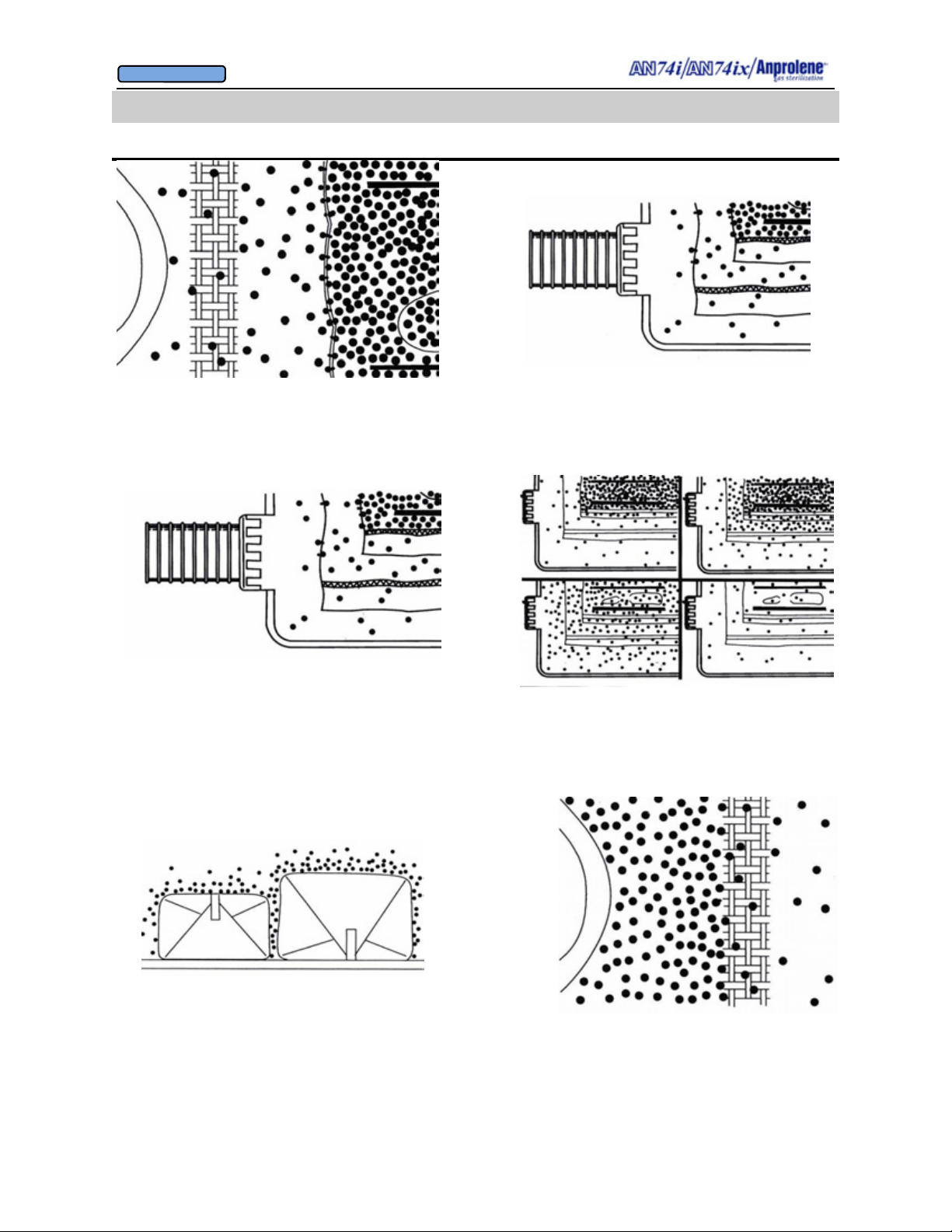
7. EtO gas readily passes through cloth, paper, and Seal
and Peel
®
Packaging to reach the items to be sterilized.
9. The EtO molecules diffusing from the liner bag into the
sterilization cabinet are then evacuated to the abator, if installed.
Any remaining effluent is then vented to the outside atmosphere
by the sterilizer’s ventilation system.
8. The walls of the sterilization bag are also porous to EtO
gas. As the concentration of EtO gas in the liner bag is
increased by gas diffusing from the gas-release bag, the EtO
molecules also diffuse through the walls of the liner bag and
into the sterilization cabinet.
10. For about three hours there are more EtO molecules
released into the liner bag than are released by the liner bag
into the sterilizer. Then the rates are similar for three hours.
Finally, the liquid Anprolene in the gas-release bag is
exhausted. EtO molecules gradually diffuse into the sterilizer
for the remainder of the cycle.
11. At 12 hours, all items are sterile, and the residual gas in the
liner bag is small. The additional two-hour purge cycle is used
to remove remaining residual EtO from the liner bag before the
container may be opened.
12. Gas-absorbent materials, like plastic and rubber, are
aired in their protective wrapping before use. The EtO
gas absorbed by plastic or rubber readily escapes through
cloth, paper, or Seal and Peel
®
Packaging.
21
Page 22

OWNER’S MANUAL
© Andersen Products Ltd
4.3 Key Operator Study Guide:
AN74I / IX Anprolene
Thank you for using the Anprolene® sterilization system.
The active ingredient in Anprolene is ethylene oxide (EtO or EO), a chemical that can be hazardous
if not handled properly. To ensure that you fully understand the safe operation of your sterilizer, we
strongly encourage you to take advantage of our Key Operator certification program.
To begin Key Operator training, please read through this study guide thoroughly. If you do not
understand any of the information in the guide, please call Andersen Customer Service for
assistance. Once you are familiar with the study guide, you can call us at (800) 523-1276 to
schedule a test.
®
Sterilizer
The test will take approximately 20 minutes. The Key Operator test is also an excellent opportunity
to ask your Andersen Representative any questions you may have about your Anprolene system or
ethylene oxide.
When you successfully complete the test, you will receive a certificate and a registered key ring.
We look forward to hearing from you.
Key Operator training is free of charge for the lifetime of your sterilizer. Please have all new
operators of your Anprolene sterilizer contact us for training before they use the system.
22
Page 23

OWNER’S MANUAL
© Andersen Products Ltd
A. Environmental Considerations
1) Temperature
• Store your Anprolene gas refill kits in a cool, secure area. We recommend storage
below 72°F (22.2°C).
• The sterilizer must be used in an area where the temperature is not less than 68ºF
(20°C) or more than 91ºF (33°C). This temperature range must be maintained
during the entire sterilization cycle.
EO FACTS: At sea level, ethylene oxide is a liquid below 51
°
Above 51
effective sterilant until 68
Anprolene sterilizer is installed remains above 68
F, EO begins to boil and converts into a gas. EO does not become an
°
F (20°C) Make sure that the room where your
°
F during the entire 12-hour
sterilization cycle. This is especially important during the winter months!
2) Humidity
• Humidity is very important to the Anprolene process. Relative Humidity (RH) must
be at least 35% in the room where item preparation and sterilization
Spores that might be on the instruments may become very dry and resistant to
Anprolene if the RH is below 35%.
• The simplest way to humidify items is to wash them.
• It is necessary to humidify items which cannot be washed by enclosing them in a
plastic bag with an Andersen Humidichip
®
or a damp sponge for four hours prior to
sterilization at a temperature greater than 68 ° F (20 ° C)
B. Preparing Items for Sterilization
Four basic steps must always be followed when preparing items for sterilization:
1) Disassemble
2) Wash
3) Dry
4) Wrap
1) Disassemble
°
F (10.6.°C).
take place.
Items containing removable parts, such as syringes, must be taken apart before washing, drying, and wrapping them to allow the Anprolene an unobstructed path.
WARNING!: Instruments which contain batteries should be taken apart and the
batteries removed and wrapped separately to protect against a spark occurring and
igniting the ethylene oxide gas.
2) Wash
Items must be washed surgically clean prior to sterilization. For cleaning, we recommend using an enzymatic detergent such as Andersen’s Sterizyme (AN2281).
23
Page 24

OWNER’S MANUAL
© Andersen Products Ltd
3) Dry
Two accepted ways to dry any item prior to sterilization with Anprolene are:
1. Towel drying
2. Drain drying (air drying).
WARNING!: Heat or hot air should never be used to dry an item prior to steriliz-
ing it with Anprolene because it will dehydrate or dry out bacteria spores making
them more resistant to the ethylene oxide gas.
WARNING!: Any water left on items may react with ethylene oxide, reducing its
efficacy. Please air dry instruments thoroughly.
4) Wrap
The following types of wrapping material are recommended for use with Anprolene:
1. Andersen Seal and Peel® Packaging (which is airtight and waterproof and greatly
extends the shelf life when heat sealed at both ends)
2. Cloth (like CSR wrap) has an estimated sterile shelf life of 30 days
3. Paper (self-seal pouches) has a shelf life of 30 days
4. Tyvek-paper pouches
☺HINT: Exposure indicators such as the Andersen AN85 or AN86 will turn color in
the presence of EO, helping to later identify items that have been sterilized.
C. Sterilization Cycle
1) Preparing the Sterilization Liner Bag
1. Place prepared items in a new sterilization liner bag.
WARNING!: Do not reuse sterilization liner bags. Even a tiny pinhole in a sterilization liner bag can allow gas to escape and cause cycle failure!
WARNING!: Do not sterilize liquids, foods or drugs in the Anprolene sterilizer. If
you have any questions about whether an item may be sterilized using Anprolene,
please call Andersen Customer Service.
2. Insert appropriate controls such as a Dosimeter (chemical indicator) or a Steritest
(biological & chemical indicator) into the least accessible part of the sterilization
liner bag. Add a Humidichip
®
if appropriate.
3. Unroll the gas release bag containing the gas ampoule and, without opening it, gently
move the ampoule to the center of the gas release bag. Place it on top of the items in
the sterilization liner bag where it will be easy to break.
®
24
Page 25

OWNER’S MANUAL
© Andersen Products Ltd
4. Insert the purge tube into the sterilization liner bag with the aluminum bobbin and
quick release fitting at the open end. Place the black Velcro® strap around the
sterilization liner bag and the bobbin of the purge tube, and pull it snug though its
loop to close the sterilization liner bag. The strap must secure the sterilization liner
bag tightly around the aluminum bobbin to keep gas from escaping.
5. Connect the quick release connector to the purge tube, if it is not already connected.
☺HINT: The sterilization liner bag may be loaded and sealed away from the steri-
lizer cabinet, and connected to the purge tube once you are ready to start a cycle.
2) Starting the Cycle
1. Make sure the AN74 i/ix power cord is connected. Press the right side of the power
switch located on the right rear of the cabinet. Wait to see the ‘AN74 I
ANPROLENE STERILIZER’ and the ‘START’ message to appear on the cabinet
display.
2. Push the button to the right of START.
3. Wait for the SELF TEST and number of elapsed PUMP HOURS to appear. (If above
18,000 hours, call Andersen for service.)
4. Press the button to the right of the PURGE message on the display and wait for the
time to count down from 1 minute 30 seconds to ‘00:00:00’. The sterilization liner
bag should compress as excess air is removed.
5. When the display indicates “BREAK AMPOULE,” carefully, so as not to puncture
the sterilization liner bag, grasp the ampoule through the sterilization liner bag and
activate it by snapping off the top.
3) Selecting Cycle Length
1. Close the door.
2. Lock the sterilizer and remove the key.
3. SELECT CYCLE LENGTH. (Right button = 12 Hour, Left button = 24 Hour)
WARNING: The usual Anprolene sterilization cycle is 12 hours, plus a 2-hour
purge cycle. When sterilizing lengths of tubing 3 feet (91.4 cm) or longer, or a full
load of gas absorbent items, it may be necessary to increase the cycle time to 24
hours with the ‘24 HOUR CYCLE’ button and to use two ampoules.
4. If an electronic beep sounds, it is an alert that 5 seconds have elapsed and the
AN 74 i/ix is awaiting a 12/24 hour cycle time selection.
5. Log sterilization data if required.
WARNING: Never interrupt a cycle once the gas ampoule has been activated. An
alarm will sound if the door is opened during the cycle.
25
Page 26

OWNER’S MANUAL
© Andersen Products Ltd
4) Unloading the Sterilizer and Determining Sterility
1. Remove the sterilized items only after the sterilization cycle and 2-hour purge cycle
have been completed and the display indicates UNLOAD STERILIZER. The
sterilizer will continue to aerate items that are not removed immediately. A count-up
timer on the display will indicate the time that has lapsed since the final 2-hour purge
cycle ended.
☺HINT: To unload the sterilization liner bag away from the sterilizer, simply de-
tach the purge probe hose from the bag using the quick release fitting at the base of
the purge probe.
2. Close the sterilizer door and press EXIT to turn off the AN74 i/ix.
3. Unload the liner bag and check the sterility (chemical &/or biological) indicators.
• Steritest provides an immediate indication of the success of the cycle (via the
Dosimeter), and later proves sterility by showing that active spores have been
killed. (Spores will require at least 48 hours of incubation to provide results.)
• The Dosimeter shows whether time, temperature and gas concentration
parameters have been met. It provides an immediate chemical indication that the
cycle was successful. Dosimeters should not be used in place of biological
indicators to prove sterility.
• Chemical exposure indicators, such as the AN85 or AN86, do not prove
sterilization. They only change color to show that the items have been exposed to
ethylene oxide.
4. Spent ampoule may be disposed of in regular trash.
☺HINT: While you may not reuse sterilization liner bags, they make great heavy-
duty trash bags!
D. Aeration
• The cabinet ventilator should be running during the entire sterilization cycle to
prevent personnel from being exposed to more than the OSHA permitted levels of
ethylene oxide. [1.0 ppm (parts per million) over an 8 hour time weighted average
(TWA)] Do not remove items before the full 2-hour purge cycle. Aeration should
take place in a well-ventilated area that provides at least 10 fresh air exchanges
per hour so that high concentrations of gas will not build up while aerating. The
purge cycle is designed to aerate most products sufficiently to meet the short-term
exposure level (STEL) of 5.0 ppm for the 15-minutes (while unloading the liner
bag).
• Metal and glass do not require additional aeration. However, items made of gas
absorbent material must be aerated at a minimum room temperature of 68° F (20°
C) for at least 24 hours prior to use. Any ethylene oxide retained in an item could
cause a serious chemical contact burn to the patient.
26
Page 27

OWNER’S MANUAL
© Andersen Products Ltd
☺ HINT: The AN74 i/ix can be used for extended aeration. A count-up timer will keep
track of the time that has passed since the standard cycle was completed. After the
regular cycle is finished, the sterilizer will continue to ventilate and purge the liner bag
until: (1) the door is opened; and (2) the EXIT button is pressed. This will turn off both
pumps and end the cycle. If the door is opened and closed and the EXIT button is not
pressed, the two pumps will continue to ventilate and purge the liner bag and cabinet.
• Extended aeration can also take place outside of the sterilizer. In this case, aeration
should take place in a well-ventilated area that provides at least 10 fresh air
exchanges per hour so that high concentrations of gas will not build up while
aerating.
E. Safety Precautions
1) Ethylene Oxide Safety
• Sterilization liner bags should never be reused because they may have a puncture or
tear.
• DANGER! Do not allow open flame or sparks near the sterilizer during the
sterilization cycle because ethylene oxide gas is highly flammable in concentrations
above 3.0% (30,000 ppm).
• The 12 and 24-hour sterilization cycles both end with a 2-hour purge cycle, which
flushes fresh air around the products in the sterilization load.
• The sterilization liner bag must be purged for 2 hours before the sterilized items are
removed to prevent the operator from being exposed to more than the OSHA
permitted level of 5.0 ppm in a 15-minute time period (STEL) while the sterilizer is
being unloaded.
• Personnel exposure to ethylene oxide can be monitored by using the personal
exposure badges, such as the Andersen AN93 AirScan
®
Badges. The AN93 AirScan
Kit has both STEL and TWA badges. EO exposure levels should be checked upon
installation of the sterilizer. We recommend that exposure testing be performed on an
annual basis.
• CAUTION. If you come in contact with liquid Anprolene, you should immediately
wash the affected area with water thoroughly for at least 15 minutes and obtain
medical attention.
2) Malfunctions and Power Failures
• In the event of a purge pump failure, the vent pump will continue to ventilate the
interior of the cabinet, exhausting gas as it diffuses through the liner bag. A PURGE
PUMP FAILURE error message will be displayed, and the sterilizer will add 24
hours of aeration before the display indicates that you may remove your products. (If
this happens, please call Customer Service for assistance.)
• In the event of a vent pump failure, the cycle will be aborted, and the purge pump
will evacuate the liner bag of any remaining gas. (If this happens, please call
Customer Service for assistance.)
27
Page 28

OWNER’S MANUAL
© Andersen Products Ltd
• If a power outage occurs during any part of the cycle, the sterilizer is equipped with a
battery back up on the circuit board that will keep track of elapsed cycle time. When
power is restored, the cycle will continue. Do not open the door of the sterilizer until
power is restored and the vent/purge systems have removed any residual gas from
the liner bag.
☺ HINT: In the case of any sterilizer malfunction or power failure, you can determine
whether sterilization was achieved by examining the Steritest biological indicator
included in the load.
3) Reasons for locking the Anprolene sterilizer:
1. To protect the contents from spark or flame.
2. To protect the liner bag from puncture.
3. To ensure the Anprolene sterilizer exhausts the ethylene oxide through the
ventilation system and abator, if installed, to the outside.
Note: No other container or sterilizer can be used with Anprolene sterilizing gas.
4) Reasons why the gas release bag containing the ampoule should never be opened:
1. To prevent the liquid ethylene oxide from coming in contact with the user or the
items to be sterilized.
2. To prevent the gas from escaping too quickly to achieve sterilization.
Things that CAN be sterilized with Anprolene:
ELECTRICAL DEVICES
SURGICAL DEVICES ENDOSCOPES
Flashlights Scalpels & sharps Endoscopes
Drills Scissors Cameras
Dremmel drills Clamps & crimpers Fiber optic scopes
Microdrills Dental tools
Saws
Rulers
Forceps
Biopsy punches
Dermal punches
Dilators
Skin staplers
Speculi
Needles
Neuter clips
IV sets
Marking pens
28
Page 29

OWNER’S MANUAL
© Andersen Products Ltd
Things that CAN be sterilized with Anprolene but that require additional aeration:
Any items that are made of rubber, plastic, cloth, are implanted or come in direct contact
with the skin, require additional aeration.
CLOTH ITEMS
TUBES IMPLANTS
Gauze Suction tubes Pacemakers
Gowns Liposuction tubes Nylon implants
Bandages Catheters Implants
Cotton balls Endotracheal tubes
Masks Feeding tubes
Drape materials Nasal tubes
OTHER ITEMS
Toothbrushes
Rubber bands
Rubber tourniquets
Sponges
Things that CANNOT be sterilized with Anprolene:
Liquids, food, and drugs should not be sterilized in ethylene oxide because it may change
their chemical composition.
29
Page 30
OWNER’S MANUAL
© Andersen Products Ltd
SECTION 5
Sundries for Use with Anprolene
30
Page 31
OWNER’S MANUAL
© Andersen Products Ltd
SECTION 5
Accessories for Use with Anprolene
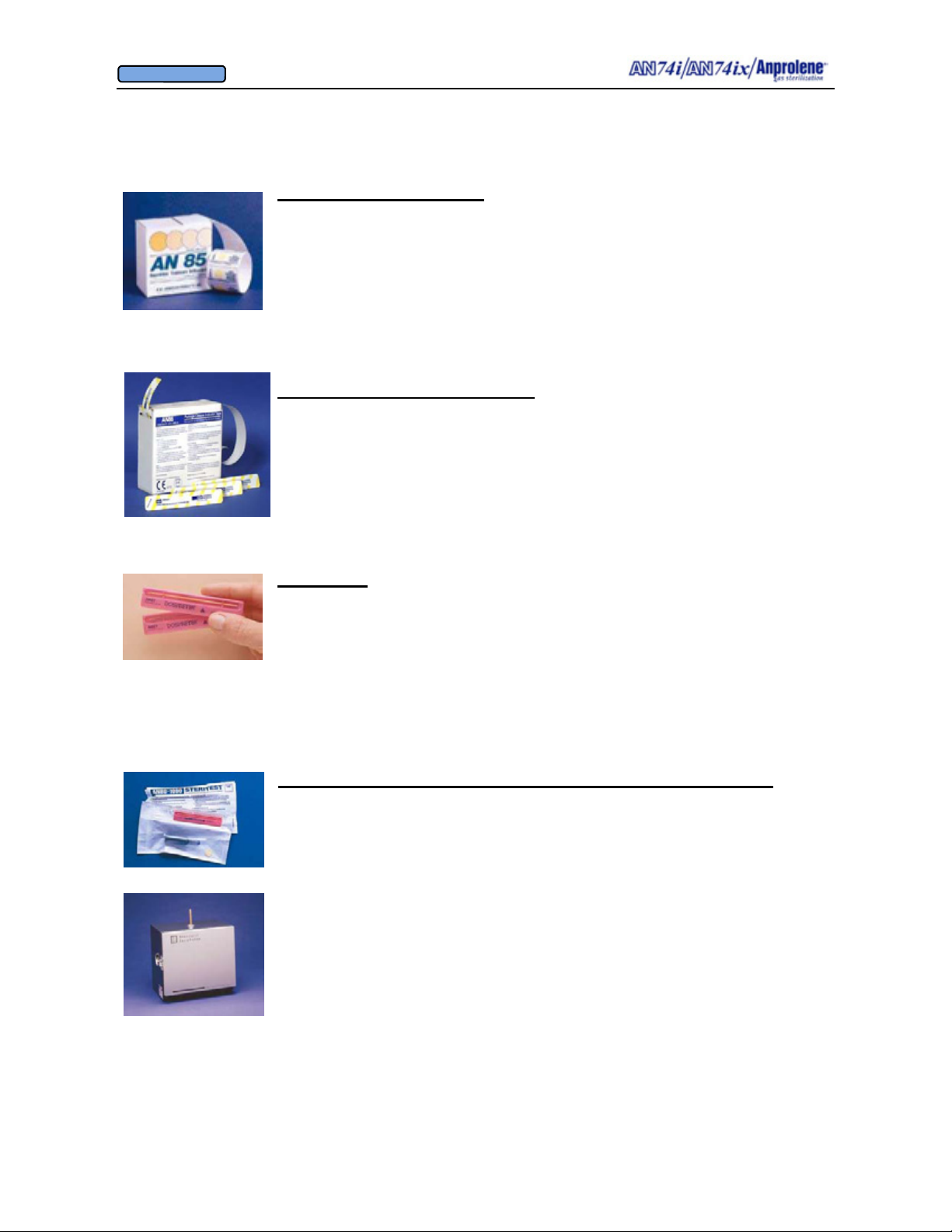
Exposure Indicator Strips
Immediate assurance of gas exposure! The strips provide a strong color
change when exposed to Ethylene Oxide. Convenient self-stick backing
adheres to conventional paper or cloth wrapping. Please note that these
strips are not intended to be an indicator of sterility. They are a quick
visual reference when placed on the outside of a package that it has been
through the sterilization process.
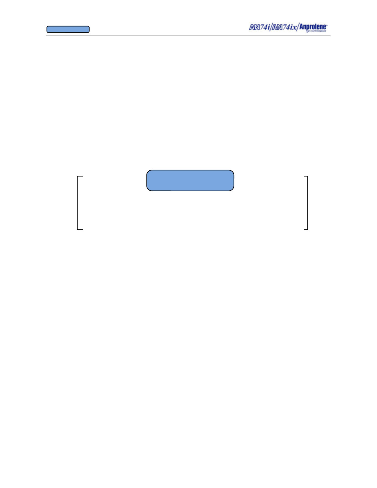
Exposure Indicator Strips AN85 200 units/box
Package Closure Indicator Strip
Get visual assurance of gas exposure and seal your packages in one
step! Strips provide a strong color change through rapid confirmation of EtO exposure. Self-adhesive strips stick to conventional
paper, CSR wrap, cloth wrapping or Andersen Seal and Peel ®.
For use with Anprolene and EOGas systems only.
Package Closure Indicator Strip AN86 200 units/box
Dosimeter®
Time, temperature, and EtO concentration are essential to proper
sterilization. The Dosimeter provides visual assurance that all of these
parameters have been fulfilled during the sterilization cycle. Results can
be viewed immediately after sterilization– no laboratory culture
necessary. We recommend the use of one Dosimeter in the least
accessible part of the load during each sterilization cycle.
Dosimeter® AN87 25 units/box
Steritest® Biological Control and Biological Control Incubator
Steritest reliably verifies that sufficient concentration of EtO killed one
million B. subtilis spores, the most resistant spore to EtO gas. Two
control components, a Dosimeter and a bacterial spore preparation in a
sterile culture medium, reduce the possibility of false positives.
The Biological Control Incubator incorporates a thermostatically
controlled 98.6°F (37°C) incubator into a tabletop unit with interior
dimensions of only 10”x 7”x 8” (25 cm x 17.8 cm x 20.3 cm).
Steritest® AN80 11 units/box
Steritest Incubator (120V 60Hz) AN810 1 per box
31
Page 32
OWNER’S MANUAL
© Andersen Products Ltd
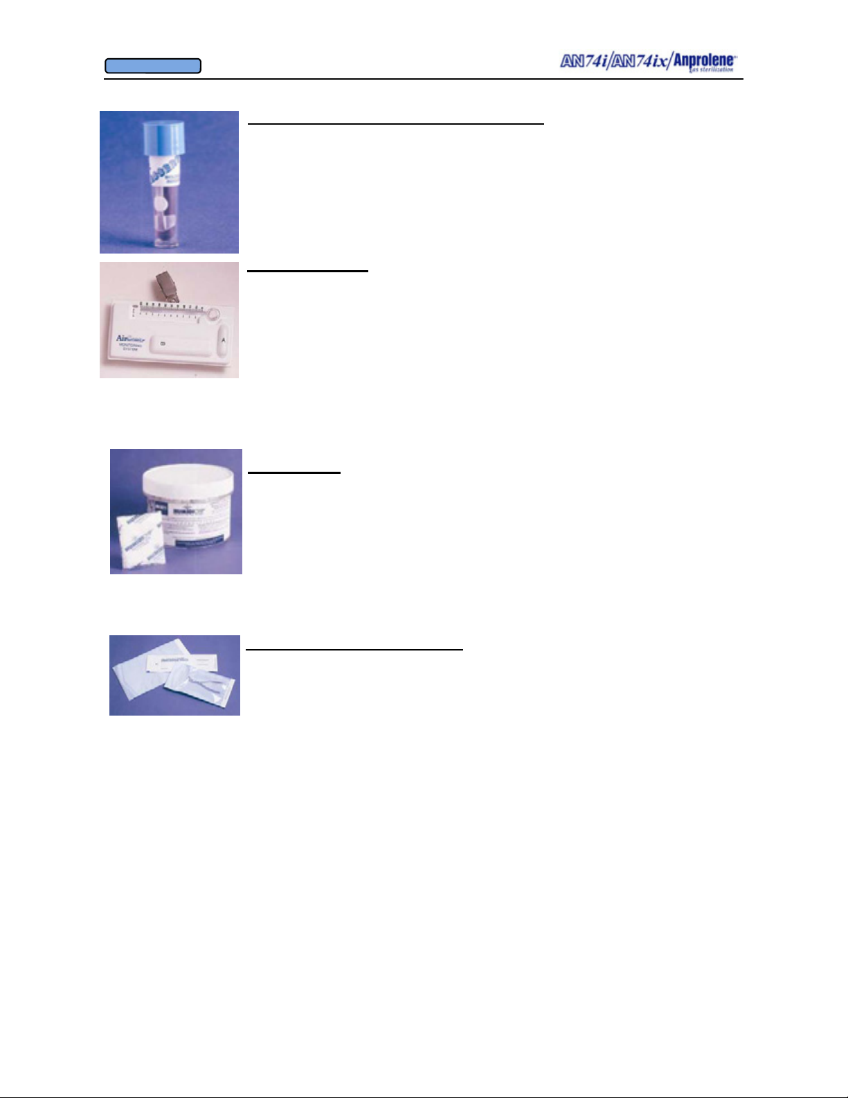
Mini Self-Contained Biological Indicators
Biological indicators test the effectiveness of EtO sterilization cycle using live
spores. High population of spores (10
Compact size allows economical storage. Color change discloses EtO test re-
sults after 48 hours incubation at 37 °C.
Mini Self-Contained Bls. AN2200 25/box
6
Bacillus subtilis) achieves accuracy.
AirScan® Badges
Single-use badges measure 15 minute short term (STEL) or 8 hour
(TWA) exposure levels to EtO. Worn in the breathing zone of the sterilizer operator, badges can document compliance with OSHA regulations.
Easy to use and provides immediate results.
AirScan® EtO Monitoring Badge
8 Hour TWA Kit AN91 1 Kit
15 Minute STEL Kit AN92 1 Kit
8 Hour TWA and 15 Minute STEL Kit AN93 1 Kit
Humidichip®
Designed specifically for use with Andersen gas sterilization systems,
this unique device ensures adequate Relative Humidity during the
sterilization cycle. Each single-use, pre-moistened, 2”x 2” (5 cm x 5
cm) Humidichip releases up to 4 grams of water vapor.
Humidichips® AN1071 25/jar
Self–Seal Sterilization Pouches
Uncoated paper/propylene-polyester peel pouches provide superior
bacterial barrier. Packaging is printed with color change indicators for
EtO and steam sterilization.
Self-Seal Sterilization Pouches
3.25” x 6.5” (82 mm x 165 mm) AN2310 200/box
3.25” x 12” (82 mm x 305 mm) AN2320 200/box
5.25” x 11” (135 mm x 280 mm) AN2330 200/box
7.5” x 14” (178 mm x 330 mm) AN2340 200/box
10” x 15” (254 mm x 380 mm) AN2350 200/box
32
Page 33
OWNER’S MANUAL
© Andersen Products Ltd
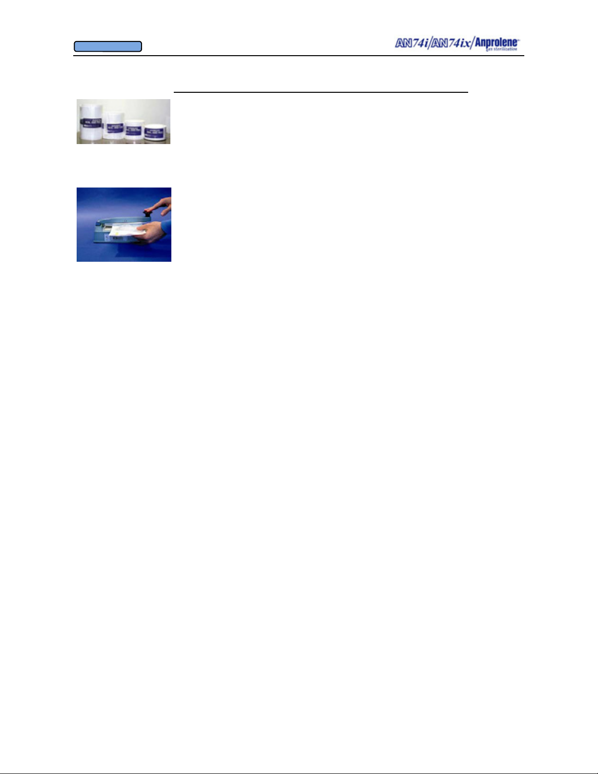
Seal and Peel® Packaging / 8” Electric Impulse Heat Sealer
Supplies tough, transparent, waterproof sealed package. Provides
extended shelf life. Resists pinholes, abrasion and tearing. Highly
porous to EtO gas for reliable sterilization and quick aeration. Available
in a wide range of widths to accommodate various instrument sizes.
Seal and Peel® Sterilization Packaging
2”(inside) x 200 ft (5 cm x 60 m) AN820 2 rolls/box
3”(inside) x 200 ft (7.5 cm x 60 m) AN830 2 rolls/box
5”(inside) x 200 ft (12.5 cm x 60 m) AN850 1 roll /box
7”(inside) x 200 ft (17.5 cm x 60 m) AN870 1 roll /box
Seal and Peel Impulse Heat Sealer AN90 1 per box
8” Seal length 110V 60 Hz or 220V 50Hz
If you have questions concerning Andersen Sterilization Accessories, contact an Andersen
Customer Service Representative at 1-800-523-1276 or 336-376-3000 or visit our website at
www.anpro.com.
33
Page 34
OWNER’S MANUAL
© Andersen Products Ltd
SECTION 6
Warnings, Troubleshooting,
Error Messages and Alarms
34
Page 35

OWNER’S MANUAL
© Andersen Products Ltd
SECTION 6
Warnings, Troubleshooting, Error Messages and Alarms
PLEASE SEE
OWNERS MANUAL
♦
The AN74 i/ix sterilizer utilizes a maximum of 36 grams of ethylene oxide gas as the
sterilizing agent in one cycle. Please refer to the MSDS for ethylene oxide included
in this manual as Appendix F, on page 67, for pre-cautions and chemical properties
related to toxicity and flammability.
♦ Do NOT open the sterilizer until the sterilization cycle is completed and the display
indicates “UNLOAD STERILIZER”.
♦ Personal protective equipment is not required for normal operation and maintenance
of this equipment.
♦ The exhaust port must be properly vented to the outside as specified starting in
Appendix B, page 46, and ending with Appendix D, page 54.
Pre-Cycle Error Messages (Before the ampoule is broken)
6.1. Vent Sensor Failure
6.2. Purge Sensor Failure
6.3. Pressure Sensor Failure
6.4. Vent Pump Failure
6.5. Purge Pump Failure
6.6 Cooling Fan Failure
6.7 Abator Failure
During Cycle Error Messages (After the ampoule is broken)
6.8. Close Door
6.9. Vent Pump Failure (During the initial 12/24 hours of sterilization cycle)
6.10. Vent Pump Failure (During the 2 hour purge cycle)
6.11. Purge Pump Failure (During the 2 hour purge cycle)
Audible Alarms
6.12 Ventilation Pump Alarm
6.13 Purge Pump Alarm
6.14 Abator Alarm
Power Outage
6.15 Temporary Loss of Power
35
Page 36

OWNER’S MANUAL
© Andersen Products Ltd
Pre-Cycle Error Messages (Before the ampoule is broken): The self test portion
of the cycle begins when the
START button is pressed and ends after the initial purg-
ing of the sterilization liner bag. Ethylene Oxide has not been released into the sterilization liner bag during the self test. Therefore, it is safe to remove the sterilization
liner bag and its contents from the machine if needed. The self test screen is shown
below.
SELF TEST
OK
1,000 PUMP HOURS
FAN 100 % RPM
If you see this screen, the controller is indicating that the ventilation sensor, purge
sensor, ventilation pump and cooling fan are all operating correctly. If an abator is
attached to the sterilizer, it indicates that the abator pump is operating correctly as
well. The bottom line on this display indicates that the cooling fan is running at
100% of its nominal revolutions per minute (RPM).
6.1. VENT SENSOR FAILURE: Failure of the ventilation sensor during the self test
portion of the cycle will show the VENT SENSOR FAILURE message on the
screen. A vent sensor failure during the self test is often caused by a defective sensor.
In this instance, the sensor needs to be replaced.
6.2. PURGE SENSOR FAILURE: Failure of the purge sensor during the self test portion of the cycle will show the PURGE SENSOR FAILURE message on the screen.
A purge sensor failure during the self test is often caused by a defective sensor. In
this instance, the sensor needs to be replaced.
6.3. PRESSURE SENSOR FAILURE: Failure of the pressure sensor during the self test
portion of the cycle will show the PRESSURE SENSOR FAILURE message on the
screen. A pressure sensor failure during the self test is often caused by a defective
sensor. In this instance, the sensor needs to be replaced.
6.4. VENT PUMP FAILURE: Failure of the ventilation pump during the self test potion
of the cycle will show the VENT PUMP FAILURE message on the screen.
Possible causes of VENT PUMP FAILURE during self test and remedies:
• The ventilation tubing has become disconnected inside the top cabinet. Reconnect
ventilation tubing.
• The ventilation vacuum pump has failed to generate the required vacuum. Replace
ventilation vacuum pump.
• The exhaust tubing from the ventilation pump is blocked. Remove obstruction.
36
Page 37

OWNER’S MANUAL
© Andersen Products Ltd
Response: The cause of failure must be identified and corrected prior to starting the
sterilization cycle.
6.5. PURGE PUMP FAILURE: Failure of the purge pump during the self test portion of
the cycle will show the PURGE PUMP FAILURE message on the screen.
Possible causes of PURGE PUMP FAILURE during self test and remedies:
• Tubing inside the bottom cabinet has become disconnected or the sterilization bag is
not properly secured to the purge tube bobbin with the Velcro strap. Reconnect tubing, recheck the integrity of the sterilization liner bag and retighten the Velcro strap.
• The purge pump failed to generate the required vacuum. Replace the purge pump.
• The purge tubing became disconnected inside the top cabinet. Reconnect purge tub-
ing.
• Exhaust tubing from purge pump is blocked. Remove obstruction.
Response:
The cause of failure must be identified and corrected prior to starting the
sterilization cycle.
6.6. COOLING FAN FAILURE: Failure of the cooling fan located in the center rear of
the top cabinet during the self test portion of the cycle will show the COOLING FAN
FAILURE message on the screen.
Possible causes of COOLING FAN FAILURE during self test and remedies:
• If the fan is running, the cooling fan blade may be partially or completely obstructed.
This is indicated by a RPM value of less than 70% on the self test screen on the
previous page. Remove the obstruction, clean the filter and reinitiate the self test.
• If the fan is running but the indicated RPM value is 0%, the white feedback wire
from the fan may not be properly connected to the PC board. Check connection.
• If the fan is not running, check the connection of the red and black lead wires to the
PC board. If they are properly connected, check the voltage at the PC board
connector for the red and white wires. If you obtain a reading of 6 VDC, replace the
fan. If you obtain a reading of 0 VDC, the PC board may need to be replaced.
6.7. ABATOR FAILURE: Failure of the abator pump during the self test portion of
the cycle will show the ABATOR FAILURE message on the screen.
Possible causes of ABATOR FAILURE during self test and remedies:
• If the BNC Connector on the back of the AN 74 I is not attached to the sterilizer or to
the Abator, the Abator pump will not start. Check the connection. Listen to the
Abator to determine if the pump is starting when START is pressed.
• Check for an obstruction in the tubing between the sterilizer and abator. If there is a
complete obstruction it can cause an abator failure. Remove the obstruction and
repeat the self test.
•
The abator pump may have failed. It will need to be replaced to continue.
37
Page 38

OWNER’S MANUAL
© Andersen Products Ltd
Response: The cause of failure must be identified and corrected prior to starting the
sterilization cycle.
Error Messages During the Cycle (After the ampoule is activated)
6.8. CLOSE DOOR: The CLOSE DOOR message is accompanied by a constant audible
alarm and indicates that the sterilizer door is open when it should be closed. There is
a magnetic sensor in the upper left corner of the door frame that senses when the door
is closed. To turn off the alarm and message, close the door of the sterilizer.
6.9. VENT PUMP FAILURE (During the initial 12 (or extended 24) hours of the
sterilization cycle): Please note that sterilization takes place during the initial 12/24
hours of the cycle. If the vent pump fails during this time, the sterilization process
has been compromised.
If the ventilation pump fails during the sterilization portion of the cycle when a sub-
stantial amount of ethylene oxide remains within the sterilizer cabinet and the sterilization liner bag, the paramount concern is the safety of the operator. If a ventilation
pump failure is sensed, the sterilizer will immediately start the purge pump. The
purge pump will then remove Ethylene Oxide from both the sterilization liner bag
and the cabinet by drawing air from the enclosed cabinet, into the sterilization liner
bag and then exhaust it to the outside thereby minimizing the risk of operator exposure. If this happens, the sterilization time and concentration of ethylene oxide inside
the sterilization liner bag has been prematurely reduced and the items in the sterilizer
should not be considered sterile.
Response:
The sterilization cycle is halted and a purge is initiated to minimize the
possibility of operator exposure to Ethylene Oxide. After the machine has completed
the two hour purge and is unloaded, the cause of the failure must be identified and
corrected prior to starting a new sterilization cycle.
CAUTION!: In this scenario, items in the sterilizer may not be sterile. Items must
be resterilized prior to use.
6.10. VENT PUMP FAILURE (During the purge cycle): The sterilization process takes
place in the first 12 hours of the sterilization cycle. If the vent pump fails during
hours 12 to 14 (or 24 to 26 during an extended cycle), the sterilization process has
not
been compromised.
Instead of the vent pump and purge running alternating two minute cycles, the purge
pump will run continuously. The purge pump will remove Ethylene Oxide from both
the sterilization liner bag and the cabinet by drawing air from the enclosed cabinet,
into the sterilization liner bag and then exhaust it to the outside thereby minimizing
the risk of operator exposure.
38
Page 39

OWNER’S MANUAL
© Andersen Products Ltd
If examination of the sterility indicators included with the load indicate adequate
time/concentration exposure to ethylene oxide, the items in the sterilizer may be considered sterile. The vent pump failure message will be displayed after the entire cycle is complete, and the door has been opened to remove the load from the sterilizer.
Response:
Sterilization cycle was completed normally. After the machine is
unloaded, the cause of the failure must be identified and corrected prior to starting a
new sterilization cycle.
6.11. PURGE PUMP FAILURE (During the purge cycle): The sterilization process
takes place in the first 12/24 hours of the sterilization cycle. If the purge pump fails
during the purge cycle, hours 12 to 14 (or hours 24 to 26 for extended cycles), the
sterilization process has not been compromised. However, if the purge pump fails,
there will be abnormally high concentrations of Ethylene Oxide inside the sterilization liner bag at the end of the normal 14 hour cycle. In response to this failure, the
sterilizer will: (1) immediately start the vent pump, which will now run continuously
until the end of the cycle; (2) add 24 hours to the total cycle time; and (3) display a
PURGE PUMP FAILURE message on the screen.
During this additional 24 hour aeration time, most of the remaining Ethylene Oxide
will pass through the wall of the sterilization liner bag. The sterilizer will count
down 24 hours and then instruct the operator to release the Velcro strap from the
neck of the sterilization liner bag and immediately close the door. The sterilizer will
then count down an additional 2 hours of aeration time to remove any residual Ethylene Oxide from the opened sterilization liner bag within the cabinet. If examination
of the sterility indicators included with the load indicate adequate time/concentration
exposure to ethylene oxide, the items in the sterilizer may be considered sterile.
Response:
Sterilization cycle was completed normally, however, the sterilization
liner bag was not fully purged. The sterilizer will add 24 additional hours to the cycle to allow residual Ethylene Oxide to pass through the sterilization liner bag. After
the machine is unloaded, the cause of the failure must be identified and corrected
prior to starting a new sterilization cycle.
ALARMS: If a critical component of the sterilizer fails during any part of the cycle, the
controller will notify the operator by means of a visual display and an audible alarm:
6.12 Ventilation Pump Alarm: If the cabinet ventilation pump fails to maintain an adequate vacuum for 20 consecutive seconds while the ventilation pump is running, an
alarm will sound continuously and the display will read: VENT PUMP FAILURE.
The audible alarm may be silenced by pressing the EXIT button.
39
Page 40

OWNER’S MANUAL
© Andersen Products Ltd
The ventilation sensor monitors the vacuum between the cabinet ventilation pump and
the interior of the cabinet. The pressure within the cabinet relative to the room is
negative (vacuum) which ensures the sterilizing gas which has diffused through the
walls of the sterilization liner bag is retained within the cabinet.
Before the ventilation pump is turned on at the beginning of the cycle, the controller
tests to make sure the ventilation sensor is reading zero vacuum. It then turns on the
ventilation pump and checks to see if there is adequate vacuum. If the vacuum is less
than 0.25 inches of water vacuum, the VENT PUMP FAILURE message will be displayed.
During the entire sterilization and ventilation cycle, the amount of vacuum created by
the ventilation pump is also continuously monitored while the vent pump is running.
If a VENT PUMP FAILURE message is displayed, the audible alarm may be silenced
by pressing the EXIT button.
As an automated safety precaution, if the cabinet ventilation pump fails at any time
during the 12 (or 24) hour sterilization cycle, the purge pump will automatically start
and run continuously for the remainder of the sterilization and ventilation cycle. The
sterilization liner bag will be vacuumed down until the check valves in the purge tube
open at 3.0” (7.6 cm) of water vacuum. At this point the check valves will open and
the cabinet will then be vented through the sterilization liner bag for the remainder of
the cycle.
6.13 Purge Pump Alarm: Similarly, the purge pump sensor monitors the vacuum within
the tubing that connects the purge pump to the sterilization liner bag. Before the purge
pump is turned on at the beginning of the cycle, the controller tests to make sure the
purge sensor is reading zero vacuum. The purge pump is then turned on and the sterilization liner bag is vacuumed down. The controller checks to make sure the vacuum is
greater than 5.00 inches of water vacuum. Otherwise, the controller will display a
PURGE PUMP FAILURE message.
During the 2 hour ventilating bag cycle at the end of the 12 (or 24) hour sterilizing cycle, the amount of vacuum created by the purge pump is also continuously monitored
while it is running. If the vacuum created by the purge pump is inadequate for 20 consecutive seconds, a PURGE PUMP FAILURE message is displayed.
If the purge pump fails during the 2 hour ventilation cycle, the controller will
automatically add 24 hours to the cycle time to allow the remaining Ethylene Oxide
contained within the sterilization liner bag to diffuse through the walls of the sterilization liner bag as opposed to being flushed with fresh air for 2 hours, as would occur
during normal operation.
40
Page 41

OWNER’S MANUAL
© Andersen Products Ltd
The first purge cycle takes place immediately prior to activation of the Anprolene ampoule and commencement of the sterilization cycle. This cycle lasts for 1 minute, 30
seconds and is displayed as the INITIAL PURGE.
The second purge cycle is automatically initiated when the sterilization cycle has
reached the end of the 12 (or 24) hours. The purge cycle continues for two hours with
the display showing VENTILATING BAG - 02:00:00 REMAINING and counting
down to zero. At the end of the two hours, the sterilizer can be unloaded. The purge
pump runs for two minutes and then turns off for two minutes, alternating with the ventilation pump during the ventilation cycle.
If the two hour VENTILATING BAG period has expired but: (1) the door to the sterilizer has not been opened; and (2) the EXIT button has not been pressed, the sterilizer
will continue to intermittently purge the sterilization liner bag. It will remain on this
schedule indefinitely until the door is opened and the EXIT button is pressed. In addition, the display will show a count-up timer indicating additional aeration time.
6.14 Abator Alarm: The alarm will beep 3 times on startup if the abator is down to 25 or
fewer remaining cycles. A constant alarm sounds when the abator is down to 0 cycles
remaining.
6.15 Power Outage: The program in the microchip is protected from power loss by a battery which is built into the clock chip mounted on the circuit board. The design enables
the program to continue in the event of a power loss by using the backup battery
power.
If a power outage occurs during the sterilization portion of the cycle, the program will
continue without interruption as if a power outage did not occur since the items inside
the sterilization liner bag will still be exposed to the Anprolene gas for the same
amount of time even if the power is off.
If a power outage occurs during the ventilation portion of the cycle, the program will
record how long the sterilization liner bag was ventilated prior to the power outage (for
example, 30 minutes) and it will resume the countdown for the remainder of the 2 hour
ventilation cycle. (in this example, an additional 1 hour, 30 minutes).
41
Page 42
OWNER’S MANUAL
© Andersen Products Ltd
SECTION 7
Maintenance
42
Page 43

OWNER’S MANUAL
© Andersen Products Ltd
SECTION 7
Maintenance
7.1. The cabinet ventilation pump and the sterilization liner bag purge pump have an ex-
pected life of 18,000 hours (this translates to approximately five cycles per week for five
years). During this time, the pumps are designed to pump at or above minimum required
volumes of exhaust air at up to 27 inches of water backpressure. The total number of hours
that the pumps have run is displayed on the Liquid Crystal Display at the beginning of each
sterilization cycle.
When the pumps have been in operation for more than 18,000 hours (approximately 1,300
sterilization cycles), it is recommended that the complete sterilizer unit be returned to the
factory for replacement and/or refurbishment of the pumps and associated tubing. Call
Andersen Products Customer Service for return authorization and pricing.
7.2. On a semi-annual basis, or every 1,800 hours of operation, the following mainte-
nance should be performed:
a. Check the quick connect fittings and the tubing that runs from inside the upper
right hand corner of the sterilizer cabinet to the purge tube.
b. All external tubing and tubing connections that are visible, and therefore
accessible to the operator, should be checked to make sure they are secure and that
there are no visible signs of degradation such as cracking or splitting.
c. Check the exhaust tubing connections at the back of the sterilizer and perform a
leak test as detailed in Appendix D, page 55 and following.
d. The filter media attached to the cooling fan in the rear of the top cabinet should be
removed, cleaned and reattached.
7.3 All exterior surfaces and the interior surfaces of the lower cabinet should be cleaned
using a cotton cloth and a mild soap and water solution. Do not use abrasive pads as this
may mar the finish of the stainless steel and plastic molded fittings.
43
Page 44
OWNER’S MANUAL
© Andersen Products Ltd
APPENDIX A
Technical Features
44
Page 45

OWNER’S MANUAL
© Andersen Products Ltd
APPENDIX A
Technical Features
A.1. Cabinet: The AN74i/ix cabinet is assembled from grain finish stainless steel with
molded ABS front and rear end plates. The door is assembled from a molded polystyrene
outer door and inner stainless steel liner. The door is provided with an exterior grain finish
stainless steel cover panel, door support arm and latching lock with removable key.
Protective rubber feet are attached to the lower cabinet panel.
A.2. Pumps: The lower cabinet is ventilated by means of two linear oscillating pumps
located in the enclosed top cabinet. The pumps remove the air from inside of the lower
cabinet and sterilization liner bag and exhaust the air to the outside. The 3/4” (1.9 cm) inside diameter braided PVC tubing may be up to 200 feet (60.96 meters) in length. During
sterilization and ventilation cycles, the pumps maintain a negative pressure (vacuum) in the
lower cabinet with respect to the room where the sterilizer is located. If an abator is installed it uses a third linear pump that is enclosed in the abator cabinet.
A.2.a. Ventilation Pump: The cabinet ventilation pump will run continuously from
the time the operator pushes the START button at the beginning of the cycle until the 12
or 24 hour sterilizing cycle is complete. After that, during the 2 hour purge cycle, it will
alternate with the purge pump, running for two minutes and then shutting down for two
minutes until the operator:
1.Opens the door to remove the sterilized items; and
2.Presses the EXIT button.
The cabinet ventilation pump is designed to exhaust the lower cabinet at a minimum rate
of 38 liters per minute. These specifications are for a cabinet equipped with a maximum
of 200 feet (60.96 m) of 3/4” (1.9 cm) inside diameter braided PVC tubing with one 90º
bulkhead fitting at the back of the cabinet and one 90º bulkhead fitting at the interior
wall above the sterilizer.
Additional Aeration: If the operator wishes to use the sterilization cabinet to further
aerate the sterilized items after the normal 14/26 hour sterilization and ventilation cycles
are completed, the operator may simply leave the sterilizer running when the UNLOAD
STERILIZER screen appears. A count-up timer will appear on the screen showing the
additional aeration time after the end of the normal 14/26 hour sterilization and aeration
cycle. When the operator wishes to stop the additional aeration, they simply need to follow the steps outlined in A.2.a. above.
A.2.b. Purge Pump: The second exhaust pump, referred to as the purge pump, is
connected to the purge tube assembly and sterilization liner bag by a tube connected to
the front right corner of the lower cabinet. Purging is the intermittent flushing of the
sterilization liner bag with fresh air and takes place at the beginning and end of the cycle.
45
Page 46
OWNER’S MANUAL
© Andersen Products Ltd
APPENDIX B
Installation Requirements
46
Page 47
OWNER’S MANUAL
© Andersen Products Ltd
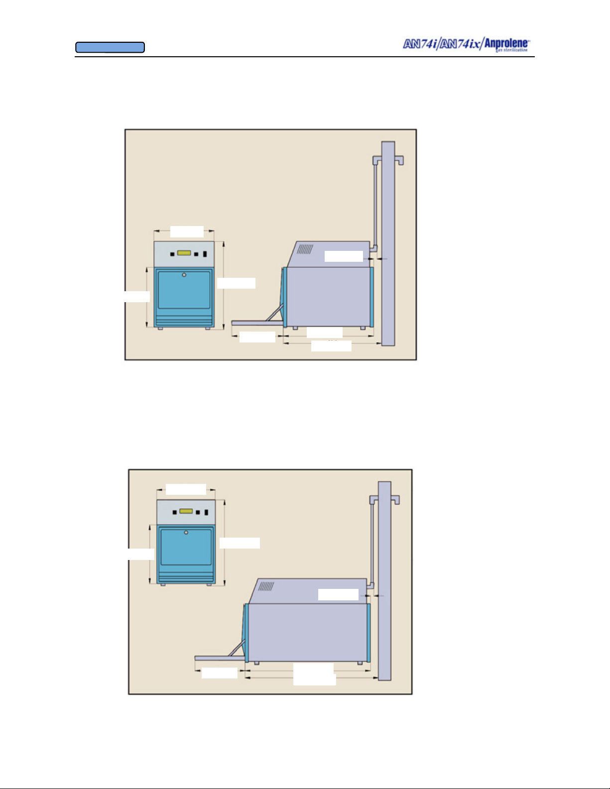
14” (35.5cm)
APPENDIX B
AN74i Anprolene Sterilizer
Dimensions and Clearances and Installation Requirements
Total weight is
approximately 50.5
pounds (22.9kg). It
is advisable to have
two persons assist in
14” (35cm)
1.5” (3.81cm)
the installation or
moving of the
machine. Refer to
installation
20.5” (52cm)
instructions in
Appendix C for
detailed instructions.
14” (35.5cm)
12” (30.5cm)
21” (53.3cm)
22.9” (58.1cm)
APPENDIX B
AN74ix Anprolene Sterilizer
Dimensions and Clearances and Installation Requirements
14” (35.5cm)
Total weight is
approximately 60.5
pounds (27.5kg). It
20.5” (52cm)
is advisable to have
two persons assist in
the installation or
moving of the
1.5” (3.81cm)
machine. Refer to
installation
instructions in
Appendix C for
detailed instructions.
12” (30.5cm)
30.5” (77.5cm)
32.4” (82.3cm)
47
Page 48

OWNER’S MANUAL
© Andersen Products Ltd
APPENDIX B
Dimensions and Clearances and Installation Requirements
B.1 The AN74 i/ix Sterilizer consists of three major components: (1) a lower cabinet which
is used to contain the items being sterilized; (2) an upper cabinet containing the controller, user
interface display and pneumatic equipment to ventilate the lower cabinet and sterilization bag;
and (3) a 3/4” (1.9 cm) I.D. exhaust tube and fittings which vent the Ethylene Oxide laden air
from the lower cabinet and sterilization liner bag to the outside.
B.2 The total weight of the AN74 i/ix is approximately 50.5 pounds (22.9 kg) / 60.5 pounds
(27.5 kg). It is advisable to have two persons assist in the installation or moving of the machine. Refer to installation instructions in Appendix C and following for detailed instructions.
Place the sterilizer cabinet on a sturdy counter space or workbench at a height convenient for
loading.
B.3 CAUTION!: The Anprolene sterilizer cabinet location must be adjacent to an U
SWITCHED, GROUNDED power outlet, preferably one that is dedicated to its exclusive
N-
use. The standard Anprolene sterilizer is fitted with a 7 foot long (220 cm) power cord.
B.4. Whenever possible, the Anprolene sterilizer should be located against an outside
wall, and exhaust directly to the outside by means of 3/4” (1.9 cm) I.D. tubing to minimize
the impedance of the exhaust system.
CAUTION!: The exhaust outlet should not be located near a common area.
48
Page 49
OWNER’S MANUAL
© Andersen Products Ltd
APPENDIX C
Installation Instructions for
New Anprolene Users
49
Page 50
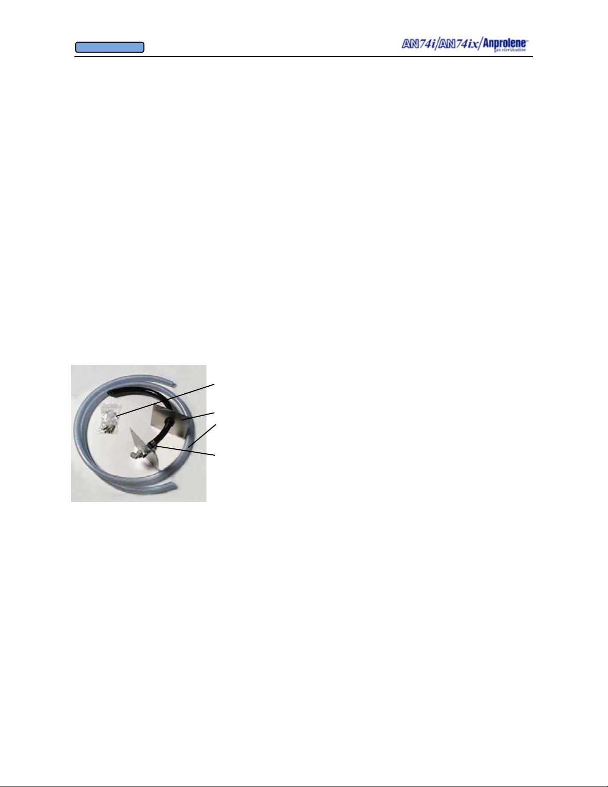
OWNER’S MANUAL
© Andersen Products Ltd
APPENDIX C
Installation Instructions for New Anprolene Users
C.1 Unpacking - The combined upper and lower sterilization cabinet weighs
approximately 50.5 pounds / 60.5 pounds. To avoid possible injury, it is recommended that
two persons assist in removing the sterilizer from the shipping box and placing the sterilizer
wherever it will be used.
To unpack the sterilizer, gently turn the packing box upside down on the floor. Next, slit the
tape along the center edges of the bottom flaps and fold all four flaps down against the sides
of the box. Leave the bottom foam packing insert in place and turn the packing box back to
its original upright position. Pull the box up and off of the sterilizer. Remove the top foam
packing insert.
Each side of the painted steel enclosure has a turned under bottom edge that is raised up off
the ground approximately 3/4” (1.9 cm). One person should now take hold of the left bottom edge while the other takes hold of the bottom edge on the opposite side of the sterilizer
and lift it up out of the bottom foam insert and place the sterilizer on the counter surface
where the unit is to be installed.
Confirm that you have the following items:
• ΑΝ74 i/ix
Anprolene sterilizer upper and lower cabinet unit
• (A) Eight toggle inserts and Phillips screws to secure the
mounting plates.
• (B) Exterior wall mounting plate with black plastic bushing.
• (C) Eight foot length of 3/4" (1.9 cm) I.D. clear braided PVC
tubing and two stainless hose clamps (included with sterilizer).
• (D) Interior wall mounting plate with 90° elbow fitting
assembly and 20" (50.8 cm) length of black 3/4" (1.9 cm) I.D.
tubing for through wall penetration
• (E) Owner’s Manual
C.2 The following tools will be needed for installation of the sterilizer:
• Electric drill
• 3/8” (0.95 cm) drill for the toggles
• 1/4” to 3/8” diameter drill bit that is longer than the exterior wall is thick
• 2” (5.08 cm) hole saw
• Medium flat blade screwdriver
• Medium Phillips screwdriver
• Razor knife, and
• Soapy water solution in a squirt bottle for leak testing.
C.3 Temporarily position the sterilization cabinet in the appropriate location, as described
in Appendix B.
50
Page 51
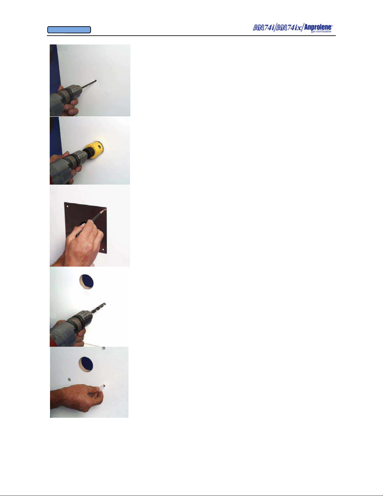
OWNER’S MANUAL
© Andersen Products Ltd
C.4 Interior Wall Mounting: Choose a location on the wall that is
directly above the exhaust bulkhead fitting coming out of the back
of the sterilizer (See lower picture on page 3). This is the location
where the exhaust hose will run through the wall to the outside.
CAUTION! Make sure you are not drilling into any struc-
tural members, wires or pipes. With the long drill bit, drill all
the way through to the outside.
C.5 Using a 2” hole saw bit, enlarge the pilot hole on the interior surface of the wall to 2”. Repeat this process on the exterior
surface of the wall using the pilot hole as the center point. You
should now have a 2” hole through the entire wall.
C.6 Take the Interior wall plate assembly (marked "D") with
the 90 degree elbow attached and insert the black tube through the
hole to the outside. Center the tube inside the 2” diameter hole
and mark the location of the four plastic toggles.
C.7 Remove the interior wall plate assembly and drill the four
toggle mounting holes using a 3/8” (.95 cm) bit.
C.8 Insert four of the toggles into the interior mounting holes
and tap them flush against the inside surface of the wall.
51
Page 52
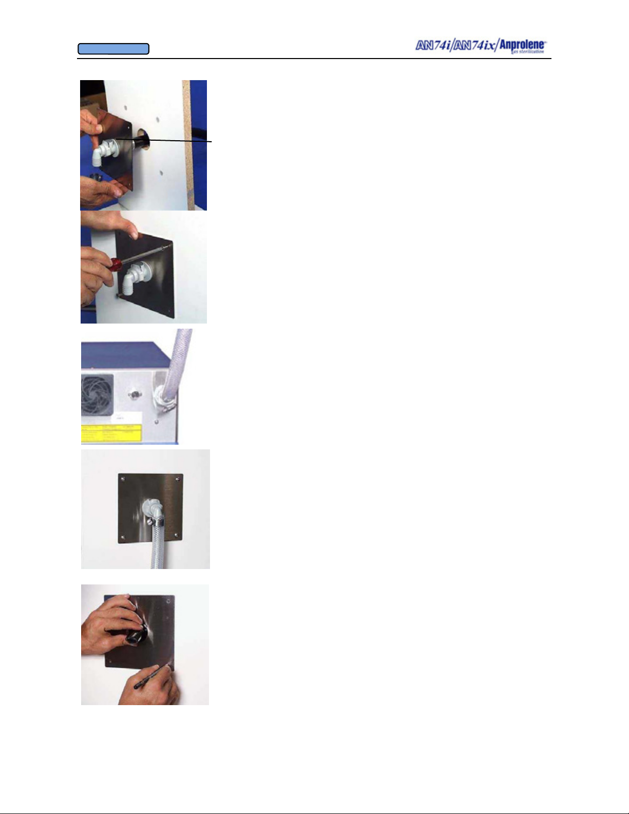
OWNER’S MANUAL
© Andersen Products Ltd
C.9 Insert the black hose that is attached to the interior plate
assembly into the two inch hole and line up the four mounting
holes with the four toggles.
The gray interlock button on the fitting should be facing up.
C.10 Secure the interior mounting plate assembly to the interior
wall by threading the Phillips screws into the four toggles.
C.11 Take one end of the eight foot length of 3/4" (1.9 cm) I.D.
clear braided PVC tubing and slip one of the stainless steel hose
clamps over the end. Next, push the tubing as far as it will go
onto the 90 degree hose barb connector on the back of the cabinet.
Then secure the PVC hose by tightening the stainless hose clamp
with a flat blade screw driver.
C.12 Move the sterilizer into its permanent location and then
stretch the clear braided PVC tubing up to the 90 degree wall
mount fitting. Allow for an extra inch or two and cut to length.
Slip a stainless steel hose clamp over the tubing and then push the
tubing as far as it will go onto the 90 degree hose barb connector.
Secure the PVC tubing with the second stainless steel hose clamp.
C.13 Exterior Wall Mounting: Slide the exterior mounting plate
over the black PVC tubing that extends out through the 2” hole
and then mark the four mounting holes.
52
Page 53
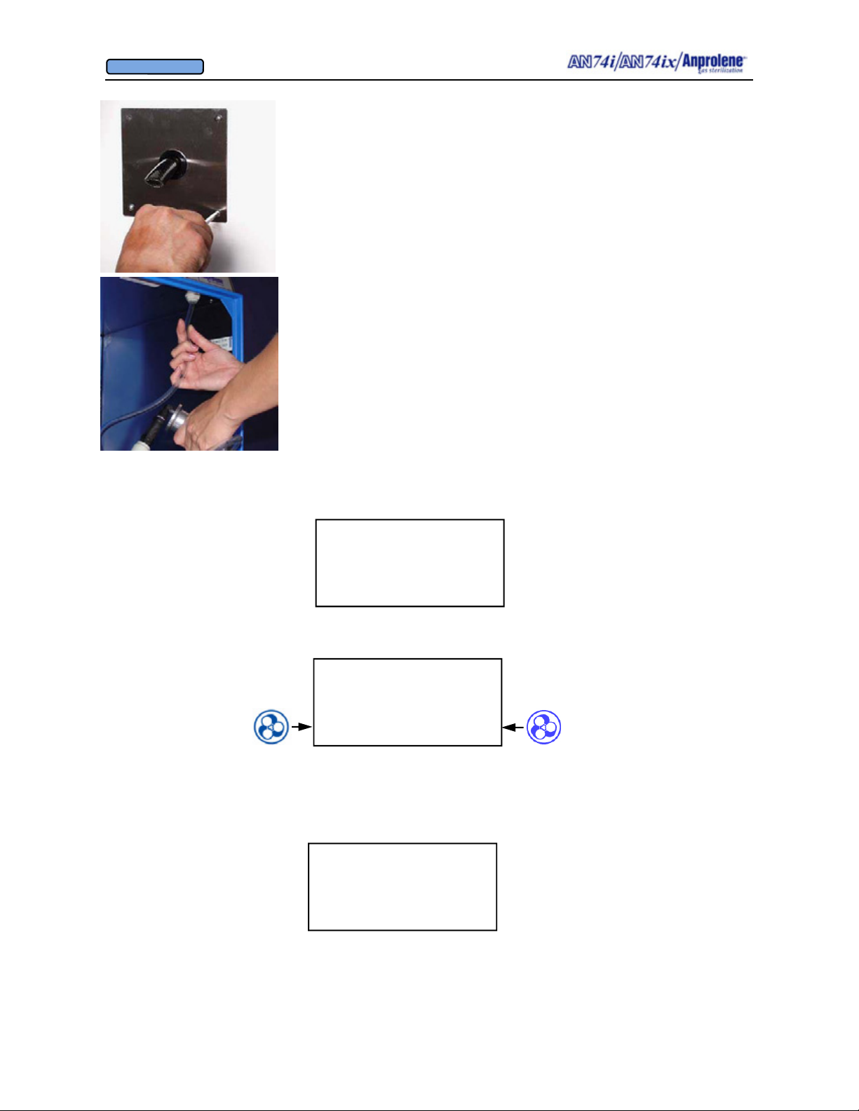
OWNER’S MANUAL
© Andersen Products Ltd
C.14 Repeat steps C.7 and C.8 by drilling the four toggle mounting holes and inserting the toggles. Secure the exterior plate to the
wall with the four Phillips screws provided. Depending on the
thickness of your exterior wall, you may wish to trim off excess
black tubing that protrudes from the exterior plate with a utility
knife. Make sure you leave at least three inches protruding out
from the metal plate and make sure you cut the tubing at a 45 degree angle with the long end of the cut on the top of the tube.
C.15 Initial Operation - Once the installation of the exhaust tubing is complete, ensure that the purge tube is connected inside the
cabinet. The purge tube connects the sterilizer via an acetyl quick
connect fitting that is located on the front right corner of the lower
cabinet’s ceiling. Check to make sure the power cord is connected
to the back of the sterilizer and is plugged into an un-switched,
grounded power outlet.
C.16 Turn the sterilizer on with the black power switch located
on the back right corner of the upper cabinet. The sterilizer will display the following
screen:
AN74 I
ANPROLENE STERILIZER
START
C.17 Press the button next to START and the sterilizer will perform a self test on the
cabinet ventilation pump.
AN74 I
ANPROLENE STERILIZER
START
C.18. The display will then show the current version of the microchip program, and “OK”
indicating the cabinet ventilation pump is functioning properly. It will also display the total
number of hours that the evacuation pumps have been running since the unit was manufactured. The bottom line displays a number indicating the blade speed of the rear cooling fan.
SELF TEST
OK (VER. 4.04)
16 PUMP HOURS
FAN 100 % RPM
53
Page 54

OWNER’S MANUAL
© Andersen Products Ltd
C.19. At the end of the initial self test, the following screen will be automatically displayed.
Pressing the button to the right of PURGE will cause the sterilization bag purge pump to
operate for 1 minute, 30 seconds. This, in turn, will cause air to flow through the sterilization liner bag, up the 1/4" (.64 cm) I.D. purge tube into the purge pump, and then out the
3/4” I.D. exhaust tube creating an exhaust pressure of approximately one to three inches of
water inside the exhaust tube at the rear of the sterilization cabinet.
LOAD STERILIZER BAG
CLOSE BAG OVER TUBE
PURGE BAG
EXIT PURGE
C.20 Checking Connections - The final step in the installation process is to make sure the
fitting connections outside the cabinet are airtight. One method of testing for leaks is to
squirt a soapy water solution onto the connections when the sterilizer pumps are running as
explained below.
C.21. While the pumps are running, squirt or pour a small amount of
the soapy water solution onto the visible connections. If you see any
air bubbles that are growing larger, this is an indication that air is
escaping from the fitting. Tighten the stainless hose clamps further
until the bubbles stop getting larger.
C.22. At the end of the initial purge cycle, the following screen will
appear. If you do not want to run a cycle at this time you may simply turn the power off by pressing the on/off switch on the right rear
corner of the top cabinet.
BREAK AMPOULE
CLOSE DOOR
SELECT CYCLE LENGTH
24 HOUR 12 HOUR
The unit may now be placed into service as instructed in Section 3,
beginning on page 12..
54
Page 55
OWNER’S MANUAL
© Andersen Products Ltd
APPENDIX D
Installation Instructions for
Current Anprolene Users
55
Page 56
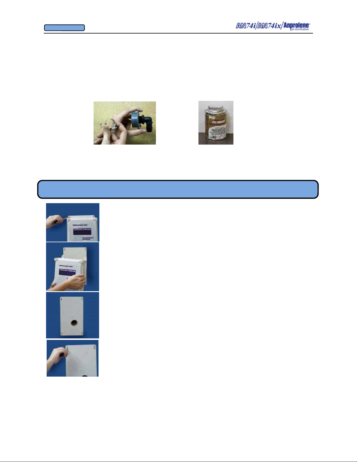
OWNER’S MANUAL
© Andersen Products Ltd
APPENDIX D
Installation Instructions for Current Anprolene Users
The following instructions are for current users of ventilated AN74C, D or E Anprolene®
systems. The adaptor kit included with your new sterilizer allows for an easy conversion
from the 2” outlet hose used with earlier Anprolene systems to the 3/4” I.D. outlet hose of
the AN74 i/ix.
The following items are included in the adaptor kit:
1 PVC adaptor PVC glue
1 90º hose barb fitting
1 Stainless steel hose clamp
Section D.1. Directions To Remove Blower and Check Previous Installation of Pipe
D.1.1 Remove the existing ventilation unit from the wall by
removing the 4 small metal screws at each corner.
D.1.2 This will expose the plastic mounting plate underneath.
D.1.3 At the time of initial installation, the 2” pipe leading to the
outside should have been sealed with a light coat of
silicone caulking and pressed firmly into the hole in the
mounting plate. To check whether or not this occurred,
remove the 4 remaining screws and gently test the
connection between the pipe and the mounting plate by
rotating the plate.
If the pipe is not secure, continue on to Section D.2. If the pipe is secure, reattach the
mounting plate with the original 4 screws, and advance to Section D.3.
56
Page 57

OWNER’S MANUAL
© Andersen Products Ltd
Section D.2. Securing the PVC
D.2.1 Clean the Mating Surfaces. Remove the mounting plate from the
wall and clean the outside surface of the 2” PVC pipe as well as the interior
surface of the tube extending from the back of the plate with rubbing alcohol
and allow to dry.
D.2.2 Correct Position of the Wall Plate. After the PVC glue is applied as
detailed in the next paragraph, you must quickly slide the mounting plate all
the way onto the pipe until it bottoms out against the lip of the mounting
plate. Then you must immediately align the four holes in the mounting plate
with the four mounting toggle holes in the wall by rotating the mounting
plate as needed.
D.2.3 Gluing the Wall Plate to the PVC Tube. Apply a thin film of PVC
glue to each of the mating surfaces. QUICKLY press the wall plate onto
the PVC pipe. The glue acts as a lubricant, so it will easily slide in. NOTE:
There can be no delay in sliding the wall plate onto the pipe after applying the glue. The glue dries in seconds and any delay may prevent correct alignment. Wipe off any excess PVC glue from the interior of the pipe
with a paper towel
D.2.4 Secure the Mounting Plate to the Wall. Screw the mounting plate to
the wall using the original 4 small screws.
Section D.3. Inserting the PVC Adaptor
D.3.1 Before inserting the PVC adaptor, test the fit by placing the adaptor
into the hole. If necessary, clean the mating surfaces with rubbing alcohol.
D.3.2 Apply a thin film of PVC glue to each of the mating surfaces, including the inside of the 2” PVC pipe.
57
Page 58
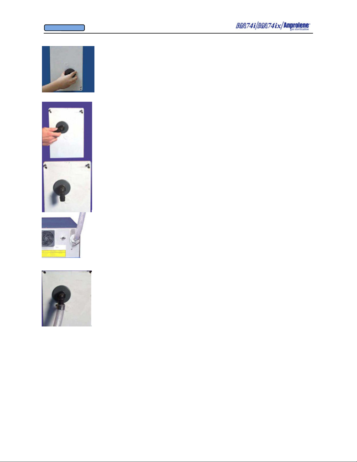
OWNER’S MANUAL
© Andersen Products Ltd
D.3.3 QUICKLY press the adaptor all the way into the hole. The glue
acts as a lubricant, so it will easily slide in. NOTE: There can be no de-
lay in sliding the adaptor into the hole after applying the glue. The
glue dries in seconds and any delay will prevent correct placement.
D.3.4 Screw in the black nylon 90º hosebarb fitting and align the barb end
such that it is pointing down.
D.3.5 Take one end of the eight foot length of 3/4" (1.9 cm) I.D. clear
braided PVC tubing and slip one of the stainless steel hose clamps over
the end. Next, push the tubing as far as it will go onto the 90 degree hose
barb connector on the back of the cabinet. Then secure the PVC hose by
tightening the stainless hose clamp with a flat blade screw driver.
D.3.6 Move the sterilizer into its permanent location and then stretch the
clear braided PVC tubing up to the 90 degree wall mount fitting. Allow for
an extra inch or two and cut to length. Slip a stainless steel hose clamp over
the tubing and then push the tubing as far as it will go onto the 90 degree
hose barb connector. Secure the PVC tubing with the second stainless steel
hose clamp.
D.3.7 Refer to Section C.15 and the following steps on page 53 of the manual for initial operation and leak testing the connections.
58
Page 59
OWNER’S MANUAL
© Andersen Products Ltd
APPENDIX E
Software/User Interface Flowcharts
59
Page 60
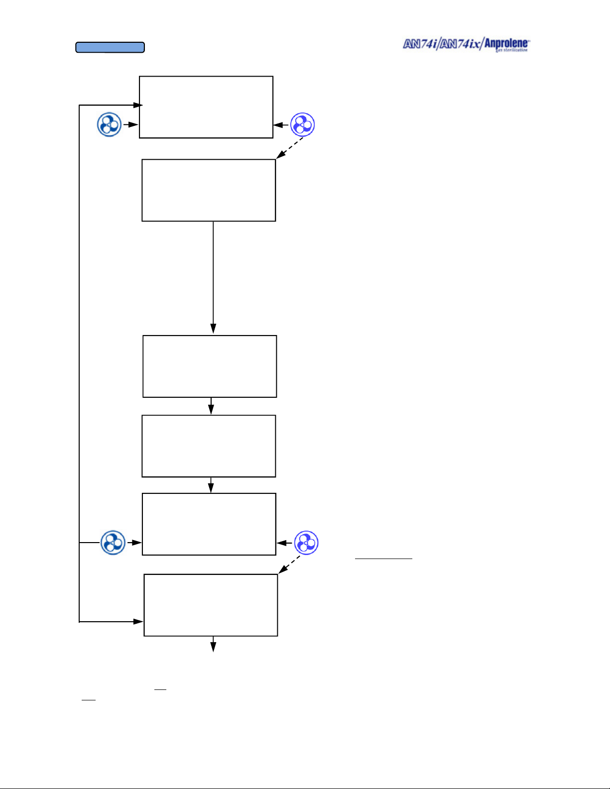
OWNER’S MANUAL
© Andersen Products Ltd
Flowchart for Normal Operating Screens
AN74 I
ANPROLENE STERILIZER
START
250 ABATOR CYCLES
REMAINING
SELF TEST
VER 4.04
1,000 PUMP HOURS
FAN 100 % RPM
SELF TEST
OK
1,000 PUMP HOURS
FAN 100 % RPM
LOAD STERILIZER BAG
CLOSE BAG OVER TUBE
PURGE BAG
EXIT PURGE
INITIAL PURGE
00:01:30 REMAINING
EXIT
When
START
pressed
When
PURGE
If Abator Attached (optional):
On initial startup the sterilizer will indicate the num-
ber of remaining abator cartridge cycles.
Initial Abator Self Test:
1. Abator Cartridge - checks cycles remaining
(countdown). If more than 25, continues without
change in display. If equal to or less than 25 cycles remaining, beeps 3 times to notify operator.
If cycles remaining equals 0, the machine beeps
continuously. The cartridge has expired and
should be replaced. Additional cycles are not
recommended but the screen may be bypassed by
pressing the BYPASS button.
2. Abator Pump - tests vacuum on exhaust line
Initial Self Test:
1. Cooling Fan Speed – tests fan speed as a percentage of nominal speed
2. Purge Sensor - checks purge sensor offset value
3. Ventilation Sensor - checks ventilation sensor
offset value
4. Back Pressure Sensor - checks back pressure
sensor offset value
5. Purge Pump - tests vacuum on inlet to purge
pump
6. Ventilation Pump - tests vacuum on input to
ventilation pump
7. Back Pressure - tests pressure on exhaust line
PUMP HOURS
This message is displayed every time the
START button is pressed. It displays the total
number of hours that the ventilation pump
(VENT PUMP) has operated. The pump
should be serviced or replaced on a regular
schedule. See the maintenance information in
Section 7 of this manual for details.
The ability to EXIT the
cycle at this point is to
allow the operator to
return to the standby
state if the ampoule has
not been broken.
Continued next page
60
Page 61
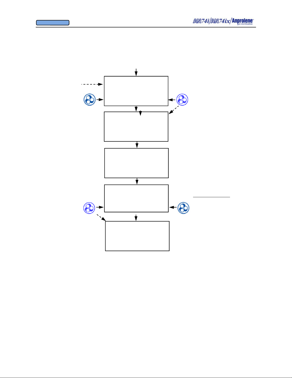
OWNER’S MANUAL
© Andersen Products Ltd
Flowchart for Normal Operating Screens, continued
Continued from previous page
After the initial
purge has been completed, the operator
breaks the ampoule
and closes the door.
If the operator does
not select the cycle
length within 5 seconds, an alarm will
sound continuously
as a reminder.
At the end of the cycle,
the operator opens the
door and removes the
load. The operator then
closes the door and
presses the EXIT button.
This returns the sterilizer to the standby
state.
BREAK AMPOULE
CLOSE & LOCK DOOR
SELECT CYCLE LENGTH
24 HOUR 12 HOUR
12 (or 24) HOUR CYCLE
STERILIZING
11:24:15 REMAINING
VENTILATING BAG
01:23:55 REMAINING
UNLOAD STERILIZER
00:18:54
EXIT
AN74 I
ANPROLENE STERILIZER
START
When cycle
length selected
During the ventilating bag cycle, the
purge pump and cabinet ventilation
pump run alternating two minute
cycles such that at least one pump is
running all the time, but two pumps
never run at the same time.
Additional aeration:
The purge pump and the ventilation pump continue running
alternate two minute cycles
until the door is opened and
the EXIT button is pressed.
Therefore, items may be left in
the machine for further aeration after the cycle has ended.
61
Page 62
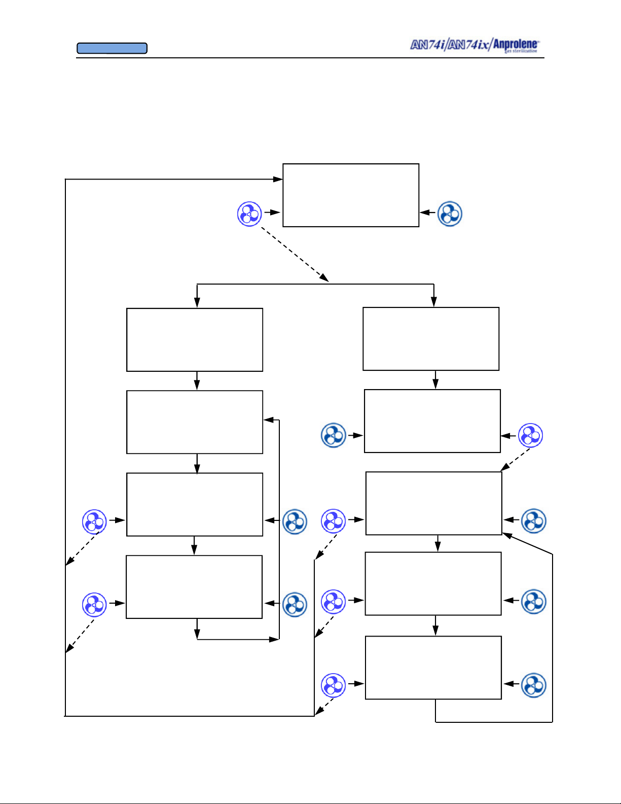
OWNER’S MANUAL
© Andersen Products Ltd
Flowchart for Technical and Diagnostic Screens
These screens are used by authorized service technicians and installers only, to check the vacuum created
by the abator pump, ventilation pump and purge pump. The screens are used for diagnostic and installation
purposes and would not normally be used by the operator of the machine.
AN74 I
ANPROLENE STERILIZER
When left
button held for
3 seconds
START
No pumps
running,
all sensors
should
equal 0.
Test Purge
pump
Test Vent
pump
If no Abator
attached
DIAGNOSTICS
NO ABATOR
PURG V. 0.0 (>5.00)
VENT V. 0.00 (>0.25)
BACK P. 0.0 (<15.0)
EXIT FAN 102% (>70)
PURG V. 25.3 (>5.00)
VENT V. 0.00 (>0.25)
BACK P. 6.4 (<15.0)
EXIT FAN 102% (>70)
PURG V. 0.0 (>5.00)
VENT V. 0.94 (>0.25)
BACK P. 8.2 (<15.0)
EXIT FAN 102% (>70)
If Abator
attached
DIAGNOSTICS
ABATOR ATTACHED
PRESS ABATOR TO
INSTALL CARTRIDGE,
OTHERWISE PRESS DIAG
ABATOR DIAG
PURG V. 0.0 (>5.00)
VENT V. 0.00 (>0.25)
BACK P. 0.0 (<15.0)
EXIT FAN 102% (>70)
PURG V. 25.3 (>5.00)
VENT V. 0.00 (>0.25)
BACK P. 6.4 (<15.0)
EXIT ABATOR ON
No pumps
running,
all sensors
should
equal 0.
Test
Purge
pump
PURG V. 0.0 (>5.00)
VENT V. 1.51 (>0.25)
BACK P. 8.2 (<15.0)
EXIT ABATOR OFF
Test Vent
pump
62
Page 63
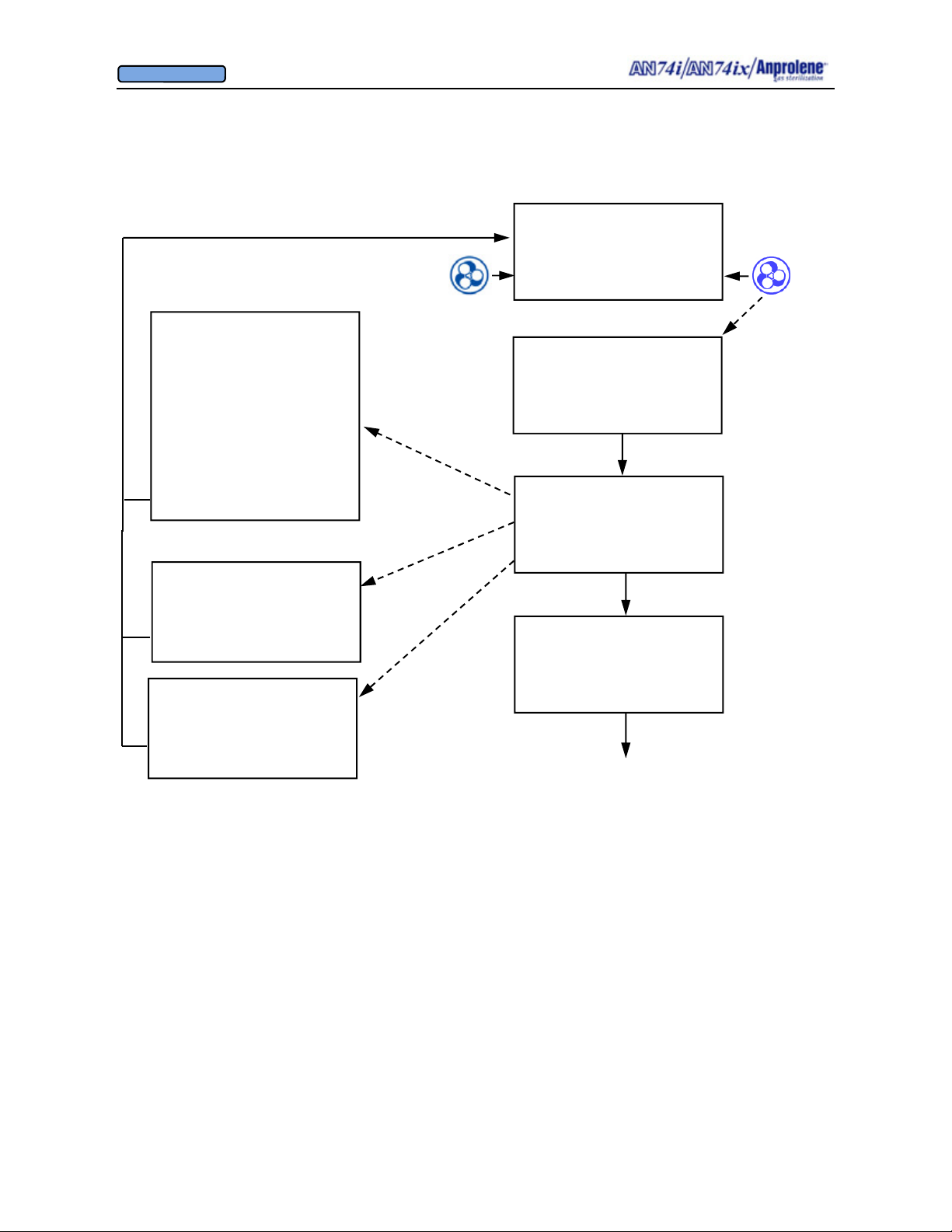
OWNER’S MANUAL
© Andersen Products Ltd
Possible Error Messages:
Flowchart for Pre-Cycle Error Messages
AN74 I
ANPROLENE STERILIZER
START
PURGE SENSOR FAILURE
VENT SENSOR FAILURE
PRESS SENSOR FAILURE
PURGE PUMP FAILURE
VENT PUMP FAILURE
ABATOR FAILURE
REFER TO ERROR
SECTION OF MANUAL
EXIT
COOLING FAN FAILURE
CHECK REAR FAN
OPERATION & FILTER
EXIT BYPASS
BACK PRESSURE HIGH
CHECK EXHAUST
TUBING & FITTINGS
EXIT BYPASS
250 ABATOR CYCLES
REMAINING
SELF TEST
VER 4.04
12,000 PUMP HOURS
94 % FAN RPM
SELF TEST
OK
12,000 PUMP HOURS
FAN 94 % RPM
Go to normal operating screens
When
START
pressed
not reach the required operating speed (70% of rated speed)
FAILURE indicates the offset of the specified sensor was out of range
(> =0.1 AND <= 0.4) prior to starting the ventilation pump.
pump failed or the purge tubing became disconnected.
or disconnected, the ventilation sensor failed or the ventilation pump
failed.
nected or the abator pump failed.
COOLING FAN FAILURE indicates the cooling fan in the top did
PURGE SENSOR, VENT SENSOR or PRESSURE SENSOR
PURGE PUMP FAILURE indicates the purge sensor or the purge
VENT PUMP FAILURE indicates the ventilation tubing is blocked
ABATOR FAILURE indicates the exhaust tubing blocked, discon-
BACK PRESSURE HIGH indicates the exhaust tubing is blocked.
EXIT returns to the startup screen
63
Page 64
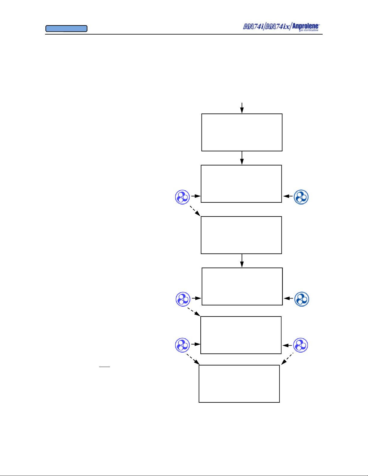
OWNER’S MANUAL
© Andersen Products Ltd
Flowchart for Ventilation Pump Failure During Sterilization Cycle
If a VENT PUMP FAILURE occurs during
the sterilization cycle, the screen will display
the error message, and the machine will beep
continuously until the ALARM button is
pressed. This alerts the operator to the problem. The purge pump will start and remain on
for the remainder of the normal cycle time.
Press ALARM OFF
to stop the alarm
In this case, sterilization has been stopped during the cycle and the Ethylene oxide in the
liner bag was removed by the purge pump.
ITEMS IN THE LINER BAG SHOULD NOT
BE CONSIDERED STERILE
The machine may be unloaded once the
counter reaches 0:00:00, but the items in the
liner bag should be resterilized prior to use
12 (or 24) HOUR CYCLE
STERILIZING
1:24:15 REMAINING
STERILIZATION HALTED
VENT PUMP FAILURE
1:24:15 REMAINING
ALARM OFF
STERILIZATION HALTED
VENT PUMP FAILURE
1:21:55 REMAINING
UNLOAD STERILIZER
STERILIZATION HALTED
VENT PUMP FAILURE
EXIT
Refer to the Error and Troubleshooting sections
of the manual for information about repairing the
sterilizer
To reset the machine, shut off the machine power.
Then, while holding both
power. Release buttons after the display shows
characters.
buttons, turn on the
VENT PUMP FAILURE
REFER TO ERROR
SECTION OF MANUAL
RESET
AN74 I
ANPROLENE STERILIZER
START
64
Page 65
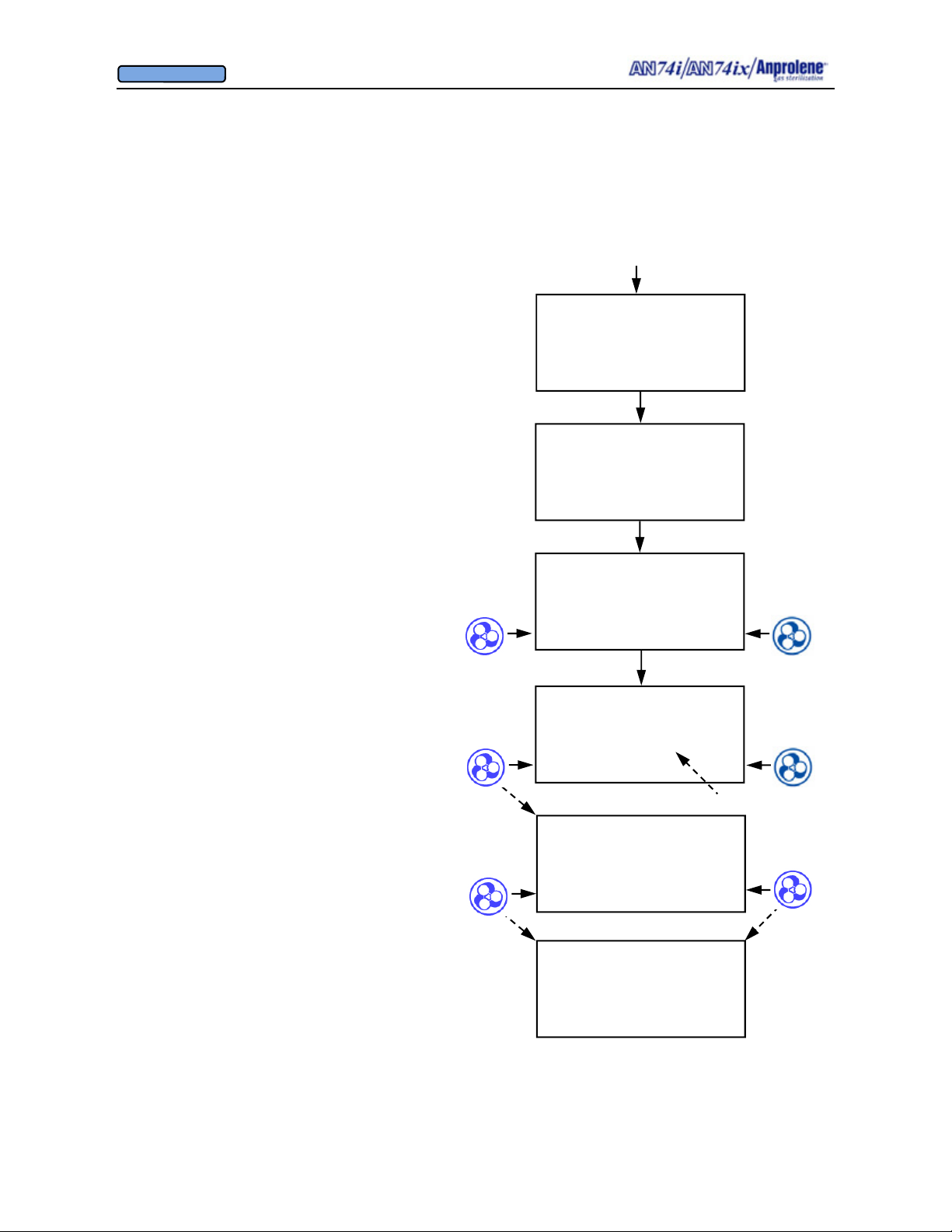
OWNER’S MANUAL
© Andersen Products Ltd
Flowchart for Ventilation Pump Failure During Ventilation Cycle
12 (or 24) HOUR CYCLE
STERILIZING
1:53:15 REMAINING
If a VENT PUMP FAILURE occurs during
ventilation cycle, the screen will display the
error message, and beep continuously until
the ALARM button is pressed. The purge
pump will remain on for the remainder of
the normal cycle time and will ventilate the
cabinet.
Press ALARM OFF
to stop the alarm
In this case, sterilization has been completed prior to the failure of the pump.
ITEMS IN THE LINER BAG MAY BE
CONSIDERED STERILE
The machine may be unloaded once the
counter reaches 0:00:00, and the items may be
used normally
VENTILATING BAG
0:20:12 REMAINING
VENTILATING BAG
VENT PUMP FAILURE
0:20:01 REMAINING
ALARM OFF
UNLOAD STERILIZER
VENT PUMP FAILURE
00:02:55
EXIT
Count up timer
VENT PUMP FAILURE
REFER TO ERROR
SECTION OF MANUAL
Refer to the Error and Troubleshooting sections of
the manual for information about repairing the
sterilizer
To reset the machine, shut off the machine power.
Then, while holding both buttons, turn on the
power. Release buttons after the display shows
characters.
RESET
AN74 I
ANPROLENE STERILIZER
START
65
Page 66
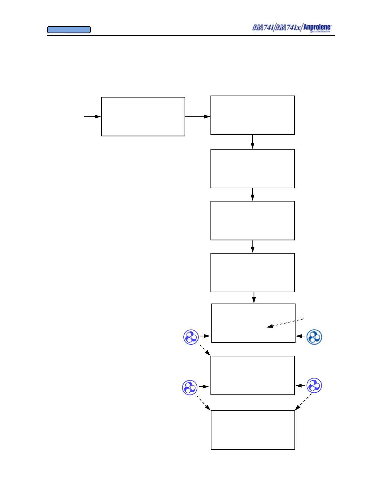
OWNER’S MANUAL
© Andersen Products Ltd
Flowchart for Purge Pump Failure During Ventilation Cycle
12 (or 24) HOUR CYCLE
STERILIZING
1:24:15 REMAINING
If a PURGE PUMP FAILURE
occurs during the ventilation
cycle, an additional 24 hours
will automatically be added to
the time remaining
The PURGE PUMP FAILURE message will
remain on the screen. At the end of the extended cycle, the operator should: (1) open the
door; (2) remove the Velcro strap and open the
mouth of the bag; and (3) close and lock the
door.
Continue ventilation for an additional 2 hours.
Open the door and press EXIT. Then remove
the items from the cabinet as you normally
would.
ITEMS IN THE LINER BAG MAY BE
CONSIDERED STERILE
VENTILATING BAG
0:23:55 REMAINING
VENTILATING BAG
PURGE PUMP FAILURE
24:00:00 REMAINING
PURGE PUMP FAILURE
OPEN DOOR
REMOVE VELCRO STRAP
CLOSE DOOR
PURGE PUMP FAILURE
01:59:59 REMAINING
Refer to the Error and Troubleshooting sections
of the manual for information about repairing the
sterilizer
To reset the machine, shut off the machine power.
Then, while holding both buttons, turn on the
power. Release buttons after the display shows
characters.
UNLOAD STERILIZER
00:00:44
EXIT
PURGE PUMP FAILURE
REFER TO ERROR
SECTION OF MANUAL
RESET
AN74 I
ANPROLENE STERILIZER
START
Count up timer
66
Page 67
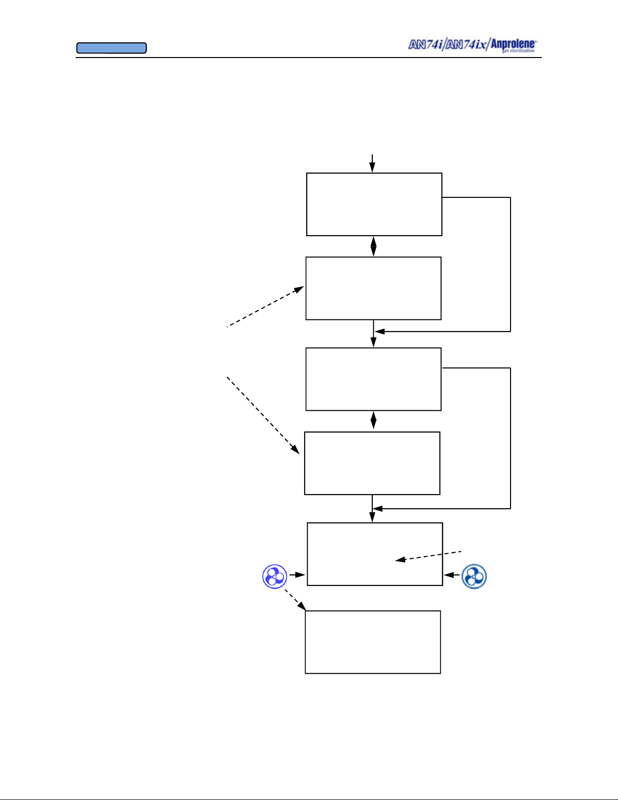
OWNER’S MANUAL
© Andersen Products Ltd
Flowchart for Close Door Error Message
Starting at the sterilizing screen,
the CLOSE DOOR message will
be displayed and the alarm will
sound if the door is opened at any
time before the UNLOAD STERILIZER screen. It has priority over
all other screens.
If the door is closed, the screen
will return to the normal time remaining screen.
12 (or 24) HOUR CYCLE
STERILIZING
1:24:15 REMAINING
CYCLE IN PROGRESS
CLOSE DOOR
1:24:15 REMAINING
VENTILATING BAG
0:00:55 REMAINING
CYCLE IN PROGRESS
CLOSE DOOR
0:00:55 REMAINING
UNLOAD STERILIZER
00:00:50
EXIT
AN74 I
ANPROLENE STERILIZER
START
Count up timer
67
Page 68
OWNER’S MANUAL
© Andersen Products Ltd
APPENDIX F
Material Safety Data Sheets
68
Page 69
OWNER’S MANUAL
© Andersen Products Ltd
APPENDIX F
Material Safety Data Sheets—Ethylene Oxide
Section 1
Chemical Product & Company Identification
Extremely flammable liquid and gas under pressure. May form
Product: ANPROLENE®
Manufactured by:
Andersen Sterilizers, Inc.
Health Science Park
3154 Caroline Drive
Haw River, NC 27258 USA
Information Telephone Number: (336) 376-8622
Emergency Telephone Num ber
(24 HRS, 7 DAYS PER WEEK)
CHEM-TEL (800)-255-3924
Section 2
Composition/ Information on Ingredients
Chemical Name: Ethylene Oxide
Weight By %: 84 to 97%
Chemical Family: Epoxide
Formula: (CH
Molecular Weight: 44.06 gms/mole
CAS Number: 75-21-8
CAS Name: Oxirane
Synonyms: EO, EtO, Dihydroxirene,
1-2 Epoxyethane, Dimethylene Oxide,
Oxane, Oxirane, Alkene Oxide, Alpha/
Beta-Oxidoethane, Oxacyclopropane.
Product Uses: Chemical intermediate for production of anti-
2)2O
freeze, polyester res in s, no n- ion ic surf a ct a nts
and specialty solvents; sterilizing agent for
controlling microorganisms in health care
applications; fumiga nt f or controll ing ins ec t
infestation in whole and ground spices and
cosmetics.
Section 3
Hazard Identification
EMERGENCY OVERVIEW
Colorless liquid or heavier-tha n- air gas wit h a sweet, ether-l ik e od or.
Extremely flammable liquefied gas which burns in the absence of
oxygen and can explode when exposed to elevated temperatures.
Toxic when inhaled. Causes severe skin and eye irrit ati on or bu rns
and respiratory tract irritation; effects may be delayed. Harmful if
swallowed or absorbed throug h the skin. Conta ct with liqu id m ay
cause frostbite.
explosive mixtures with air. Highly reactive. May be harmful if inhaled and may cause delayed lung injury, respiratory system and
nervous system damage. Inhalation may cause dizzines s or drowsiness. Liquid contact may cause frostbite. May cause allergic skin
reaction. Harmful if swallowed. May cause ad verse blo od eff e cts,
liver and kidney damage based on anim al d at a. C ance r and re pr oductive hazard.
HAZARD RATINGS: (0 = minimum; 4 = maximum)
HMIS RATING
Flammability = 4
Reactivity = 3
Personal Protection Code = x (Consult your
supervisor or standard operating procedures
for special handling directions.)
NFPA RATING
Flammability = 4
Reactivity = 3
Exposure Limits:
TWA (8 hr)
OSHA 1 ppm 5 ppm
ACGIH 1 ppm n/a
PRIMARY ROUTES OF EXPOSURE: Inhalation; eye co nta c t, skin
contact/absorption
SIGNS AND SYMPTOMS OF OVEREXPOSURE
skin, eye and respiratory tract irritation or burns. Central nervous
system effects initially cause headache, dizziness and nausea and in
extreme cases, unconsciousness and death. Peripheral nerve damage may result in muscular weakness, giddin es s , irrat iona l beha v ior
and loss of sensation in the ext remities. Dulling of the sense of smell
may occur.
INHALATION
health effects. Inhalation may progressively cause mucous membrane and respiratory irritat ion, headac he, vomiting, cyanosis, drowsiness, weakness, in coordinat io n, CNS depres s io n, la chry m a t ion,
nasal discharge and salivation, gasping, and labored breathing.
Delayed effects may include nausea, diarrhea, edema of the lungs,
paralysis and convulsions. NOTE: Ethylene oxide has a high odor
threshold (>250 ppm) and the sense of smell doe s not pr ovide adequate protection agains t its tox ic eff e ct s.
EYE CONTACT:
corrosive to the eyes and contact can cause swelling of the conjunctiva and irreversible corneal in jury . Con ta ct wit h liquid eth y len e ox ide
can cause frostbite. Vapors may cause eye irritation, tearing, redness and swelling of the conjunctiva.
Statement of Hazards:
DANGER!
: Health = 3
: Health = 3
STEL (15-min)
: Effects include
ACUTE HEALTH EFFECTS:
: Inhaling concentrated vapor may cause serious
Liquid ethylene oxide is seve rely irrit ating and
69
Page 70
OWNER’S MANUAL
© Andersen Products Ltd
SKIN CONTACT: Prolonged contact with liquid ethylene oxide can
cause a local erythema, edem a, and for m atio n of bl is te rs . Response
is more severe on damp skin. There may be a latency period of
several hours prior to the onset of symptoms. Ethylene oxide may
be absorbed by the skin, and sustained con ta c t ma y produ ce ad verse effects such as headache, dizziness, nausea, and vomiting.
Ethylene Oxide is a skin sensitizer and some individuals may suffer
an allergic skin reaction. Skin contact may also cause allergic contact dermatitis in some exposed individuals. Liquid Ethylene oxide
evaporates rapidly and may chill t he skin c au si ng frost bit e.
INGESTION:
cause severe irritation an d burns of t he mout h and throat, abdominal
pain, nausea, vomiting, c oll aps e and com a . Aspira tion may occur
during swallowing or vomiting, resulting in lung damage.
SKIN CONTACT
to be similar to acute effects of skin exposure.
EYE CONTACT:
ported.
INHALATION:
lung injury, chromosomal aberrations and peripheral neurotoxic
effects with a numbing of the sense of smell . Cognitiv e and CNS
impairment may res ult from long term exposures.
INGESTION
on liver, kidneys, and adrenal glands .
CARCINOGENICITY
OSHA classifies ethylene oxide as a can c er/ re pro du ctiv e ha z ard
and considers that, at exc es s iv e levels, ethylene oxide may present
reproductive, mutagenic, genotoxic, neurologic and skin sensitization
hazards.
ACGIH classifies ethylene oxide as “A2”- suspected human carcinogen.
NTP classifies ethylene oxid e as a known hum an carcin og en.
IARC classifies ethylene oxide in Group 1 (carcinogenic to humans).
NIOSH classifies ethylene oxide as a potential human carcinogen.
This relatively unlikely route of exposure is expected to
CHRONIC HEALTH EFFECTS:
: Long term effects are unknown but are expected
Some cases of cataract formation have been re-
Respiratory irritation which can result in permanent,
: May cause anemia, gastrointestinal irritation, effects
:
Section 4
First Aid Measures
EYE CONTACT:
face of the eyes and under the eyelids, gently but thoroughly with
plenty of running water for at least 15 minu te s . Obt ain medic a l att e ntion immediately. NOTE: Never wear contact lenses when work-
ing with ethylene ox ide.
SKIN CONTACT:
least 15 minutes while removing conta m in at ed clo thing and shoes.
Obtain medical attention immediately. Wash clothing before reuse
and discard contaminate d le ather articles such as shoes and belts.
INHALATION:
has stopped, give artificial respiration then have qualified personnel
administer oxygen, if needed. Get immediate medical attention.
Immediately flush eyes, including the entire sur-
Immediately flush skin thoroughly with water for at
Remove exposed person to fresh air. If breathing
INGESTION: If patient is conscious give plenty of wat er ( minimum
of two glasses) but DO NOT INDUCE VOMITING. This material is
corrosive. Keep head lower than hips to avoid aspiration, should
vomiting occur. Get medical at t e ntion imm ed iately.
MEDICAL CONDITIONS AGGRAVATED BY EXPOSURE
Preexisting skin, eye and respirat ory di so rd ers; lu ng, bl ood , ner v ou s
system and peripheral nerve disorders.
NOTE TO PHYSICIANS:
vomiting and irritation of the nose and throat. Pulmonary edema
may occur. Respiratory effects may be delayed. Consider oxygen
administration. If a chemical burn is pr ese nt de co ntaminate skin
and treat as any thermal burn. No specific antidote is known, however consider gastric lavage and administration of a charcoal slurry.
Respiratory symptoms include nausea,
:
Section 5
Fire Fighting Measures
FLASH POINT (TEST METHOD):
Tag Closed Cup: -4F (-20C)
FLAMMABLE LIMITS IN AIR (% BY VOLUME );
Upper flammable limit: 100%
Lower flammable limit: 3.0% (30,000 ppm)
NEFA HAZARD RATING:
Hea lth: 3 Flammability: 4 Reactivity: 3
AUTOIGNITION TEMPERATURE
804 F (429C); burns in the absence of air
EXTINGUISHING MEDIA:
spray for small fires. Water spray, polymer or alcohol resistant
foams for large fires. Dilution of liquid ethylen e oxi de with 23 volumes of water should render it non-flammable . Dilution with 100
parts water to one part of ethylene oxide vapor may be require d t o
control build up of flammable vapors in closed systems. Water spray
can be used to reduce intensity of flames to co ol fire-ex p os ed containers and to dilute spills to ren der non-flammable.
HAZARDOUS DECOMPOSITION PRODUCTS:
and carbon dioxide.
UNUSUAL FIRE AND EXPLOSION HAZARDS:
dangerously explosive under fire condi t ion ; it is fla mmable ov er an
extremely large range of concentrations in air and burns in the absence of oxygen. Liquid ethylene oxide is lighter than water (floats)
and vapors are heavier than air and may travel along gro und long
distances to sources of ignitio n and the n flas h back. Conta iners
should not be subject to temperat ures ho tt er than 12 7F (5 2 C).
Vapors are extremely flammable and are readily ig nit ed by stat ic
charge, sparks and flames at concent r ations above 3%.
:
Carbon dioxide, dry chemical or water
Carbon monoxide
Ethylene oxide is
Section 6
Accidental Release Measures
PRECAUTIONS:
Evacuate all personnel fr om the area ex c ept t ho se dir ec t ly en gag ed
in stopping the leak or in cleaning up. If an A np ro len e ampo ule is
inadvertently droppe d and ac tiv at ed before it is sealed inside of the
sterilization liner bag, it will st ill t ake t im e for the ethy len e o xi de
Treat any ethylene oxide leak as an emergency.
70
Page 71
OWNER’S MANUAL
© Andersen Products Ltd
to diffuse out of the gas release bag and in t o the ro om. At one full
minute after activation there is less than 1 ppm measured at a distance of 18 inches from the gas release bag. In the case of a premature activation the operat or sh ould imm ed iat el y:
• Place the Anprolene ampoule inside the ster ilize r
• Close the sterilizer door
• Turn the power on; and
• Press the button to the right of PURGE.
This will cause the purge and ventilation p um p s to turn on and
evacuate the ethylen e oxide f r om the st eri liz er and exhaus t it fro m
the workspace. Allow a full 14 hour cycle before you open the door
and remove the used Anprolene ampoule and dispose of it.
Section 7
Handling and Storage
HANDLING AND STORAGE PRECAUTIONS:
handling and emergency response procedures in place prior to use.
Make sure that the sterilizer is properly grounded. Protect containers from physical damage and regularly insp ec t them for crac k s or
leaks.
ENGINEERING CONTROLS:
Ethylene oxide, a major fire hazard,
can burn in the absence of oxygen. All electrical devices used in
areas processing or handling ethylene oxide must be engineered
and designed to the applicab le lo cal elec t r ic a l/ f ir e codes . S afe guards can include desig nin g elec tric a l de vi c es as exp los io n p roo f
and/or intrinsically safe. ATTENTION:
Ethylene oxide vapors are
colorless and odorless above OSHA’S permissible exposure level.
An air monitoring system and/or AirScan® badges are recom mended to determine airborne exposure levels.
STORAGE SEGREGATION:
Store ethylene oxide in a cool, dry ,
well-ventilated area away from incompatible chemicals and sources
of ignition. Store Anprolen e® ref ill k it s uprigh t; do not drop and
move in a carefully supervised manner. DO NOT STORE IN
DIRECT SUNLIGHT.
SHIPPING AND STORAGE CONTAINERS:
All Anprolene® refill kits containing ethylene oxide are packaged and
shipped in accordance with the small quantities exemption under 49
CFR 173.4(c) and DOT approva l CA 980300 5 is su ed April 9, 1998.
Section 8
Exposure Controls/Personal Protection
POSURE LIMITS:
OSHA ACTION LEVEL (8 HR. TWA) 0.5 ppm
OSHA PEL (8 HR TWA) 1 ppm
OSHA 15 MINUTE EXCURSION LIMIT 5 ppm; 9 mg/m3
ACGIHTLV/TWA 1 ppm; 1.8 mg/m3
IDLH: 800 ppm
EYE PROTECTION
working with ethylene oxide.
: NEVER WEAR CONTACT LENSES when
Have established
(See 49 CFR 173.4)
EX-
VENTILATION: Install and oper ate ge ne ral an d loc a l ex ha us t v enti -
lation systems powerful enough to maintain airborne levels of ethylene oxide below the OSHA PEL in the worker’s breathing area.
AAMI / ANSI ST41 Good Hospital Practice: Ethylene Oxide Sterilization and Sterility Assurance Guid eli nes , Se ction 3. 4 recomme nds a
minimum of 10 room makeup air changes per hour. Emission co ntrols must be in compliance with Federal, Stat e and lo ca l regulat ions .
OTHER PROTECTION
: Sterilizer must be electric ally gr ou nd ed/
bonded. Practice good personal hygiene; always wash thoroughly
after using this material. Do not eat drink or smoke in work area.
Section 9
Stability and Reactivity
Boiling Point: 50.9ºF (10.5ºC)
Freezing Point -169º F (-111.7ºC)
Specific Gravity: 0.871 at 20ºC
Vapor Pressure: 1094 mm Hg @ 20ºC
Vapor Density (Air =1) 1.5
Solubility in Water: 100%
Molecular Weight: 44.06 gms/mole
Percent Volatile by Volume 100%
Evaporation rate (Butyl Acetate = 1) Not applicable
PH: 7, neutral (100 grams/
liter in water)
Appearance and Odor: Colorless liquid or ga s
with sweet ether-like
odor. Odor threshold:
261 ppm (detectable);
600-700 ppm recogniz-
able).
Log Octanol/Water
Partition Coefficient (log Kow): -0.3
STABILITY:
Material is stable for extended periods in closed airtight, pressurized containers at room temperature, under normal
storage and handling condit io ns. Vapors m a y explo de whe n exposed to common ignition sources.
CONDITIONS TO AVOID:
Storage at warm temperatures or any
exposure of storage or shipping containe rs t o hot temp er atur es .
Prevent exposure to all so urc es of ignit ion su c h as h eat, f l am e,
lighted tobacco prod uct s, or elec t r ical or m ec h an ic al spark s .
HAZARDOUS DECOMPOSITION PRODUCTS:
Ethylene oxide
undergoes thermal decomposition to form carbon dioxide and carbon
monoxide gases.
Section 10
Toxicological Information
TOXICOLOGICAL- ACUTE INHALATION:
5748 ppm (male rat)
4439 ppm (female rat)
5029 ppm (rat – combined sexes)
LC50 (1 hr. exposure)
71
Page 72
OWNER’S MANUAL
© Andersen Products Ltd
Various mammalian species exposed to lethal concentrations of
ethylene oxide had symptoms of mucous m embra ne irrit ati on, c entral
nervous system depression, lacrimation, nasal discharge, salivation,
nausea, vomiting, diarrhea, respiratory irritation, incoordination, and
convulsions.
TOXICOLOGICAL-CHRONIC INHALATION:
exposure are similar to those obs erved in ac ut e studie s, inc l ud ing
lung, kidney and liver damage and testi cu la r t u bu le dege ne ra t ion in
some species. Studies demonstrated neuromuscular effects as the
most sensitive indica t or of et hy le ne oxid e ov er expos u re.
TOXICOLOGICAL-ACUTE DERMAL:
is available on this product. It is expect ed to be corros iv e to rabb it
skin.
TOXICOLOGICAL – CHRONIC DERMAL:
toxicity data are available on this product.
TOXICOLOGICAL- EYE:
on this product. However, it is expected to extremely irritating to
rabbit eyes.
TOXICOLOGICAL-ACUTE INGESTION:
This product is; 72 mg/kg, rat
TOXICOLOGICAL-CHRONIC INGESTION:
ingestion of this product are unkn own
CARCINOGENICITY:
epidemiology studies related to ethylene oxide concluded that the
evidence indicates t h at ethy lene oxid e does no t ca us e hea rt dis ea s e,
an excess of cancers overall, or brain, stomach or pancreatic cancers
which were seen in some animal and isol at ed human studies. The
findings with respect to leuk em ia and non- Hod gk in s lym p ho m a are
less definitive. While the majority of the evidence does not indicate
that ethylene oxide causes the s e canc ers , ther e are some suggestive
trends. Longer follow-up of ethylene ox ide wo rk ers is ne ed ed to
better clarify these relat io nshi ps. Two inhalation s t u dies with rats
demonstrated carcinogenic responses consisting of increased incidences of mono-nuclear cell leukemia, peritoneal mesot heliomas ,
and primary brain tumors. In 2-year inhalation studies with mice
there was evidence of carcinogenic activity as indicated by doserelated incidences of benign o r malignant n eo pla s m s of the ut er us,
mammary gland, and hemato po iet ic sy ste m (lym p hom a).
MUTAGENICITY:
miological studies with exposed workers, an increased incidence of
chromosomal aberrations and sister chromatid exchanges, the relevance of such effects to human health haz a rd eva lu at ion is curre ntly
uncertain. In rodent studies, dose related exposure to ethylene oxide
induces increases in numbers of adducts in DNA and hemoglobin.
Laboratory studies with mice have shown th at ac ut e expo sure to
ethylene oxide at 300 ppm and above c au se d tes t ic ul ar inju ry as
evidenced by concentrati on-re lated increased embryonic deaths
following mating of exposed males to non-exposed females
(Dominant-Lethal Test).
NEUROTOXICITY:
exposure, namely headaches , nausea, diarrhea, lethargy, and
irrational behovior. Muscle weakness, loss of sensation in the
extremities and a reduction in the sense of smell and/or taste may
also result. Studies on workers Indic at e th at CNS and co gn it iv e impairment may result from chronic exposures t o ethyl en e oxide.
No eye irritation animal data are available
A recent assessment of available
While ethylene oxide has demonstrated, in epide-
Effects are similar to those of acute (sho rt term )
Symptoms of chronic
No dermal LD50 information
No chronic dermal
The acute oral LD50 for
The effects of chronic
REPRODUCTIVE EFFECTS: Some limited epidemiological data
suggests that women exposed to ethylene oxide have a greater
incidence of miscarriages. A one-generation reproduction study in
rats showed decreased number of pups at 100 ppm, but not at 33
ppm. In a two-generation reproduction study involving exposure of
rats to ethylene oxide vapor for 5 hrs/day, 5 days/week, there was
parental toxicity at 33 ppm and 100 ppm. The no-observable effect
concentration for adult toxicity, offspring effect and reproductive
effect was 10 ppm.
TERATOLOGY:
exposed to ethylene oxide vapor at concentrations of 50 ppm, 125
ppm and 225 ppm showed that maternal toxicity occurred at 125 and
225 ppm. Fetotoxicity, evidenced by reduced fetal body weight,
occurred at all concentrations. At 225 ppm and to a lesser extent at
125 ppm an increased incidence of skeletal variants was found.
There was no evidence of embryotoxicity or malformations.
TARGET ORGANS:
skin, eyes, respiratory system, liver, kidneys, brain, blood, reproductive system, and central nervous system.
Inhalation development toxicity studies with rats
Overexposure to this product may affect the
Section 11
Ecological Information
ECOTOXICOLOGICAL DATA:
ene glycol. Biodegradation of et hylene ox id e oc c urs at a moder at e
rate after acclimation (3-5% degradation after 5 days; 52% after 20
days). Biodegradation is ex pe cted in a wast ew at er treat m e nt pla nt.
Ethylene oxide has an estimated half-life in the atmosphere of 211
days. A high adsorptivity in soil is expected.
Ethylene oxide hydrolyze s to ethy l-
Section 12
Disposal Consideration
WASTE MANAGEMENT/DISPOSAL:
ampoules, sterilization liner bags, indicators and accessories as you
would ordinary trash.
However, unused Anprolene ampoules containin g ethylene oxide
are a RCRA hazardous waste with waste code U115 (Commercial
chemical product - listed for toxicity and ignitability). Unused
Anprolene ampoules co nt ai nin g eth y len e oxi de m a y be incine ra te d in
an approved hazardous waste incinera to r or can be biolog ic all y
treated in an approved fac ilit y . Unused Anprolene ampoules containing ethylene oxide are banned from land disposal.
Dispose of waste materials in accordanc e with all applicable Federal,
State and local laws and regulations .
Dispose used Anprolene
Section 13
Transport Information
TRANSPORTATION DATA
DOT Proper shipping Name: Ethylene Oxide
DOT Class or Division: 2.3 (Poison Gas)
Identification Numb er UN 1040
Packing Group: n/a
DOT Label: “This package conforms to 49 CFR
173.4”
DOT Packaging See section 7, “Handling and stor
age”
DOT Approval: CA-9803005
:
72
Page 73
OWNER’S MANUAL
© Andersen Products Ltd
Section 14
Regulatory Information
U.S. REGULATIONS:
TSCA status: Listed
CERCLA Section 103 (40 CFR 302.4): listed
10 lb. Reportable Quantity
SARA Section 304 (40 CFR 356.40): Listed
1 lb Reportable Quantity
SARA Section 311/312 (40 CFR 370.21) Hazard categories met:
Acute, Chronic, Fire, Reactive, Sudden Release
SARA Section 313 (40 CFR 372.65); Listed
OSHA (29 CFR 1910. 1200): Meets criteria as a hazardous material
OSHA (29 CFR 1910. 1047): Et hylene Oxide Standard
EPA list of Hazardous Air Contaminants: Listed
EPA Organic Hazardous Air Pollutant (HAP) list: Listed
EPA list of Pesticide Chemicals (40 CFR 180.151): Listed
EPA NESHAPS (40 CFR 63.360)
VOC Rule: 100% VOC
Section III– Permissible Exposure
STATE RIGHT-TO-KNOW REGULATI ONS
:
California Proposition 65: Listed; cancer hazard; reproductive hazard
California Director’s List: Listed
Florida Hazardous Substance List: Listed
Massachusetts Extraordinarily Hazardous Substance List: Listed
Minnesota Hazardous Substa nce List : L isted
New Jersey Hazardous Substance List: Listed on 0882
(Special Hazardous Substance: Environmental
Hazardous Substance)
Pennsylvania Right-to-know List: Listed
Section 15
Other Information
GLOSSARY OF TERMS AND ABBREVIATIONS
Section V - Fire and Explosion Hazard Data
ACGIH- American Conference of Governmental Industrial Hygienists
CERCLA- Comprehensive Environmental Response, Compensation
and Liability Act.
CAS- Chemical Abstract Service
CFR- Code of Federal Regulations
CNS- Central Nervous System
DOT- U.S. Department of Transportation
EPA- U. S. Environmental Protection Agency
HMIS- Hazardous Materials information Sheet
IARC- International Agency for Research on Cancer
IDL- ingredient Disclosure List
IDLH- Immediately danger ous t o life and health
HAP- Hazardous Air Pollutant
50 - Median lethal dose that kills 50% of a n expos e d po pu lation by
LC
the inhalation route
50- Median lethal dose that kills 50% of an exposed population by
LD
the oral (or dermal) route
NESHAPS- National Emission Standards for Hazardous Air Pollutants
NFPA- National Fire Protection Association
NIOSH- National Institute of Occupational Safety and Health
NTP- National Toxicology Program
:
OSHA- Occupational Safety and Health Administration
p/p- parts per part
PEL- Permissible exposure Limit
PVC- Polyvinyl chloride
ppm- Parts per million
p.s.i.g- Pounds per square inch (gauge pressure)
RCRA- Resource, Conservation and Recovery Act
SARA- Superfund Amendment and Reauthorization Act of 1990
STEL- Short-term exposure Limit
TDG-Transportation of Dangerous Goods
TLV- Threshold Limit V a lue
TSCA- Toxic Substance Control Act
TWA- Time Weighted Average
VOC- Volatile organic compound
WHMIS-Workplace Hazardou s Mater ial I nf o rmat ion Sy s tem
MSDS Revision Date: 10/23/02
Disclaimer
It is imperative that the user/reade r be f amiliar with and adhere to
OSHA regulations which are specific to et hy le ne oxide
(29CFR1910.1047) as well as any other applicable Federal, State, or
local government regulat ion s. Regulations lis ted in Section 14 of this
document may not be all inclusive and are subject to change. The
data in this MSDS is furnished gratuitously independent of any sale
of the product only for your invest igat io n and inde pe nd en t verification. While the information is believed to be correct, Andersen
makes no representation as to the accur acy of the information con tained herein. Andersen shall in no event be responsible for any
damages of whatsoever nature dir ectly or indirectly resulting from
publication or use of, or neglige nc e upo n da t a conta ine d he re in. No
Warranty (either expres se d or im plied) of m erc ha nt ab ility or of fitness
for any purpose with respect to the product or to the data herein is
made hereunder
MSDS Revision Date: 9/08/04
73
Page 74
OWNER’S MANUAL
© Andersen Products Ltd
APPENDIX G
AN74 i/ix Specifications
74
Page 75
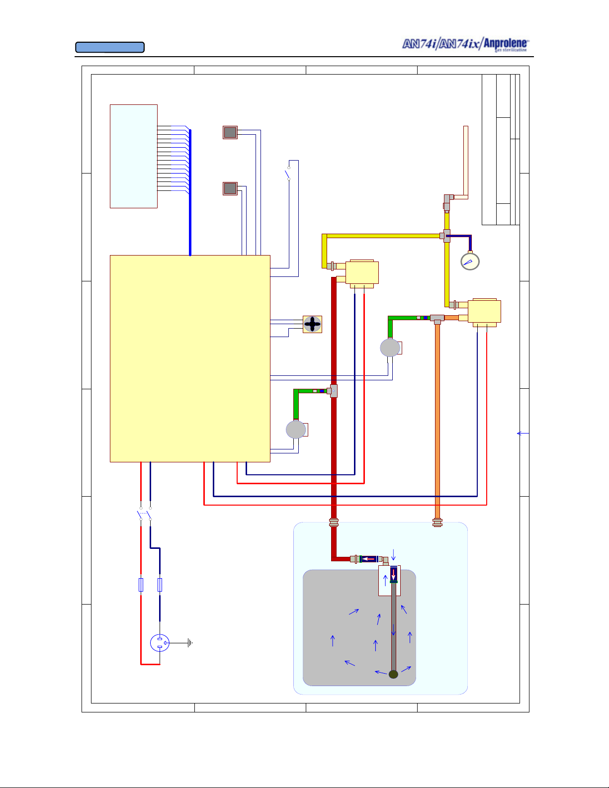
OWNER’S MANUAL
© Andersen Products Ltd
D
C
B
A
AISUC
1
6
20 X 4 LCD
AN74 i
START
16
15
14
13
12
11
10
9
8
7
6
5
4
3
2
1
ANPROLENE STERILIZER
54321
LCD
MOMENTARY PUSHBUTTONS
LEFT BUTTON
RIGHT BUTTON
DOOR
KEYPAD
VS3
0.75" ID TUBING
DOOR SWITCH
RED = PURGE TUBING
TUBINGS (1/2" OD):
ORANGE = VENTILATION TUBING
GREEN = TO VACUUM SWITCH
YELLOW = TUBING WITH COAT
BH = BULKHEAD UNION
FITTINGS:
CLOSE WHEN DOOR CLOSES
RED
BLACK
WHITE
COOLING FAN
MC1
P
THOMAS
V
12VDC
MC = MALE CONNECTOR
6025SE
PUMP
115VAC
PURGE PUMP
90 DEG
ELBOW
FITTING
BULKHEAD
TEE3
MC2
FOAM FILTER
1/64" ORIFICE
TEE2
Title
PRESSURE GAUGE
P
6025SE
THOMAS
V
VS2
L. Lee
1
AN74 i SYSTEM SCHEMATIC
Number RevisionSize
Print: Design:3-OCT-2002
B
Date: 14-Oct-2002 Sheet of
File: G:\ENGINEERING\AN74_I\Sch_PCB\AISUC.DDBDrawn By:
PUMP
115VAC
VENT PUMP
POWER SWITCH
AN74 i
CONTROLLER
VS2VS1 SV1
5VDC
FOAM FILTER
1/64" ORIFICE
RSS-495-204
CLEVELAND CONTROLS
0.19" w.c.v.f.-vert
VS2:
TEE1
WITH .06" HOLE
VS1
5VDC
B_L
LINE
NUE
115 VAC
FUSE 2A
FUSE 2A
B_N
115 VAC
P_L
P_N
115 VAC
VS1:
RSS-498-205
CLEVELAND CONTROLS
4.00" w.c.v.f.-vert
BH1
CONNECTOR
CHECK VALVE
BOBBIN
BH2
CABINET
BAG
PLUG
115VAC
1 2 3 4 56
D
C
B
A
75
Page 76
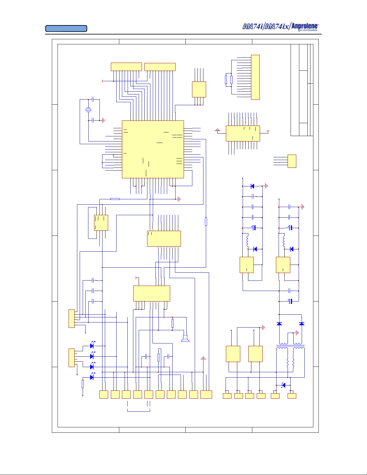
OWNER’S MANUAL
© Andersen Products Ltd
SDA
GND
R7 2. 21K
B
16
GND
15
14
D7
13
D6
12
D5
11
D4
10
D3
9
D2
8
D1
7
R1 20
D4D3D2D1D0
8
AD4
AD5
U2
9
D5D6D7
SSR
AC
SSR1
3
1
2
P_N
D0
6
EN
5
GND
4
R/W
3
GND
2
VCC
1
GND
GND
7
6
5
4
1
AD3
AD2
AD1
AD0
VSS
AD7
NC
AD6
NC
3
2
11
10
16
VCC
4
FB
Vin
U6 LM2575-5
1
PUR
1
2
+5
GND
AC
4
2
1
P_L
R/WASCSDSVCC
14
15
AS
R/W
MOT
NC
NC
NC
21
20
LC2 330
2
Vout
ON
5
SSR2 SSR
2
LCD
13
17
18
CS
DS
VCC
RST
VCC
24
NC
SQW
IRQ
DS12887
22
23
19
D5
1N5819
C11
0.01
C10
0.01
C9
0.01
C3
1000
D4
1N5819
GND
3
BLO
1
2
+5
GND
AC
AC
3
4
1
1
2
B_N
B_L
R2 20
12
TEMP
3
2
TEMP
A
AICUE
L. Lee
11
AN74 i CONTROLLER
Number RevisionSize
B
Title
Date: 14-Oct-2002 Sheet of
File: G:\ENGINEERING\AN74_I\Sch_PCB\AICUE.DDBDrawn By:
4
GND
3
KEY2
2
KEY1
GND
1
KEYPAD
C8
0.01
+12V
C7
0.01
C2
330
D3
LC1 100
4
U5 LM2575-12
1
D1
T1 14A-30-24
1
2
1
LINE
1N5819
2
FB
Vout
GND
3
Vin
ON
5
C6
0.01
C1
2200
3A
D2
3A
9
10
7
Z1
12
3
4
6
JP2
JP1
2
1
NEU
1 2 3 4 56
9
KEY1
DS
57
P3.2
BUSWIDTH
A6/P.6/PM.2
ANGND
13
VCC
14
E
12
2BEEP
10
CS
56
P3.3
P3.4
Vref
Vss
14
GND
VCC
E
5
1
R/WASEN
54
55
P3.6
P3.5
RESET
EXTINT/P2.2/PROG
16
15
U3 74HC540
E
E
4
C13
0.01
1
Red
C
5
3
4
2
KEY2
D0D1D2D3D4D5D6
53
52
51
50
P3.7
P4.0
P4.1
P4.2
8XC196/KB/KC/KD
P1.1
P1.0
TXD/P2.0/PVER
RXD/P2.1/PALE
20
19
18
17
POWER
TEMP
E1
SV2
9
19
1
E2
E1
D8
Q8
11
SVA1
SVA2
11
15
3B
4B
1C
2C
3C
4C
2
8
10
16
R4 2.21K
VCC
1
2SV1
Black
6
49
P4.3
P1.2
21
SDA
VSW2
8
D7
Q7
12
VS2
6
2B
DOOR
2DOOR
48
22
KEY1
VSW1
7
13
VS1
3
9
7
P4.4
P1.3
D6
Q6
1B
CLAMP
47
23
KEY2
BLOWER
6
14
BLO
1
8
9
10
RG1 15K
VCCWPSCL
SDA
5
6
7
8
WP
SCL
VCC
A2
A1
A0
U8 AT24C01A
4
3
2
1
D7
GND
44
46
45
P4.5
P4.6
P4.7
T2CLK
P2.3/
READY
VCC
43
T2RST/P2.4/AINC
DOOR
42
WRH/BHE
41
WRL/WR
40
PWM/P2.5
39
P2.7/T2 CAPTURE/PACT
38
SV1
Vpp
37
VCC
Vss
36
GND
HS0.3
35
HS0.2
34
P2.6/T2UP-DN
33
PURGE
HOLD/P1.7
32
WDI
HLDA/P1.6
BLOWER
31
BREQ/P1.5
30
SV2
HS0.1
29
HS0.0
28
HSI.3
P1.4
HSI.0/SID.0
24
25
PURGE
HEATER
4
5
D4
D5
Q4
Q5
16
15
PUR
CLAMP
R5 475
C12
0.01
2SV2
1
27
HSI.1/SID.1
HSI.2
26
SV1
POWER
2
3
D1
D2
D3
Q1
Q2
Q3
18
17
ALARM
HUMI
2HUMI
1
1
2
1
HEATER
D
1
2
3
4
5
6
7
6
X1
54321
6
5
4
3
2
1
RG3 15K
VCC
L1
6
5
L2
4
3
2
1
RG4 1K
L3
VCC
L4
R6 4.75K
+12V
RG2 15K
VCC
C5
22pF
16MHz
C4
22pF
VCC
GND
VCC
VCC
GND
VS3
VS2
VS1
R3
475
8
6
7
5
PFO
RST
WDI
WDO
PFI
GND
VCC
MR
U7 MAX705
4
3
2
1
VCC
C16
10
C15
10
C14
0.01
VSW1
VSW2
1
2VS2
1
2VS1
8
HEATER
SCL
WP
60
59
58
P3.0
P3.1
RD
61
ALE/ADV
62
INST
63
64
CLKOUT
65
XTAL2
66
XTAL1
67
Vss
68
Vcc
1
EA
2
NMI
3
ACH3/P0.3
4
ACH1/P0.1
5
ACH0/P0.0
6
ACH2/P0.2
7
8
ACH7
9
ACH5
ACH4
U1
10
12
11
HUMI
GND
VCC
U4 ULN2068
13
VS3
+12V
1
1
2VS3
White
FAN
COOLING
D
C
B
A
76
Page 77
OWNER’S MANUAL
© Andersen Products Ltd
APPENDIX H
Equipment Ratings Summary and
Replacement Parts List
77
Page 78

OWNER’S MANUAL
© Andersen Products Ltd
APPENDIX G
Equipment Ratings Summary
Equipment Rating
Model Ref. Voltage Hz. Power Fuse Rating
AN74.67 AN74i 115v +/- 10% 50/60 150 Watts 2 Amp.
AN74.68 AN74i 230v +/- 10% 50/60 150 Watts 2 Amp.
AN74.69 AN74i 100v +/- 10% 50/60 150 Watts 2 Amp.
AN74.87 AN74ix 115v +/- 10% 50/60 150 Watts 2 Amp.
AN74.88 AN74i 230v +/- 10% 50/60 150 Watts 2 Amp.
AN74.89 AN74ix 100v +/- 10% 50/60 150 Watts 2 Amp.
Environmental Conditions
The Anprolene Sterilizers are designed to function in an environment with these conditions:
i. Indoor use;
ii. Altitude up to 6,562 feet (2000 meters);
iii. Temperature 68°F (20º C) to 91°F (33° C);
iv. Maximum relative humidity 80% for temperatures up to 87.8° F (31° C)
decreasing linearly to 50% relative humidity at 104°F (40° C);
v. Mains supply voltage fluctuations not to exceed ±10% of the nominal voltage;
vi. Transient overvoltages according to INSTALLATION CATEGORY
(OVERVOLTAGE CATEGORY) II: Local level, appliances, portable
equipment, etc. capable of withstanding 1500 volts impulse;
vii. POLLUTION DEGREE 2 in accordance with EC 664.
Connections
Nominal voltage depending upon model selected connected to a grounded, un-switched
power supply.
78
Page 79

OWNER’S MANUAL
© Andersen Products Ltd
Anprolene Sterilizers Replacement Parts List
This list relates to Models:
AN74i Model: AN 74.67 AN74ix Model: AN74.87
AN74i Model: AN 74.68 AN74ix Model: AN74.88
AN74i Model: AN 74.69 AN74ix Model: AN74.89
Part No.: Description
AN100.04 Purge Tube Bobbin Assembly
7489 Populated Circuit Board Assembly (version AICUEG)
2929 Blue hose .250" OD, .125 ID
3875 .125" Brass Hose Barb
3876 90° Brass Elbow
4710 Check Valve 3" of H2O
7409 Strap, Velcro, Hook and Loop, 10" Long x 1" Wide
7433 Tubing, 1/2" OD, 3/8" ID, Ester Based, Poly
7434 Tubing, FP, 3/8" OD, 1/4" ID
7441 Plastic Single Barb Fittings, 3/8" ID, 1/8" NPT
7443 Acetal Union Tee, 1/2" OD
7445 Acetal Bulkhead Union, 3/8"
7446 Acetal Bulkhead Union, 1/2"
7448 Female Elbow Adapter, 1/2" OD, 3/8" NPT (AN 74.69)
7449 Acetal Stem Adapter, 1/2" OD to 3/8" NPT (AN 74.69)
7450 Insert, 1/2" OD Tube
7451 Rubber Tubing, 5/8" ID with 1/8" Wall, Amber
7452 Pump, Thomas 6025SE, 100VAC, 50 Hz, 150070
7453 Pump, Thomas 6025SE, 115VAC, 60 Hz, 150057
87455 Switch, Momentary Action, Push Button
7456 D Series Miniature Power Rocker Switch, SPDT
7458 Fuse, Buss ABC-2, 250V, 1/4" x 1 1/4", 2 Amp, Fast Acting
7460 Power Cord (AN 74.67 and AN 74.69)
7461 Cable, Single-Row Receptacle, Housing to Solder Type, 16 PIN, 4"L
7464 LED Backlight, Optrex LCD 4 x 20
7468 Magnetic Proximity Sensor, Recessed, 3/8" Magnet Included
7491 Fuse Holder Receptacle
7493 Fuse Drawer (AN 74.67 and AN 74.69)
74012 Exhaust outlet
74013 90° Exhaust Insert
74014 Gauge, 30 In. of H2O
74015 Nipple, Brass with Hose
74017 .020" Aluminum Orifice
74022 .020" Gray PVC Orifice
74027 12v DC Cooling Fan
802741 Vacuum Switch (VS0.19)
802742 Vacuum Switch (VS4.0)
79
Page 80
OWNER’S MANUAL
© Andersen Products Ltd
APPENDIX I
Andersen One Year Limited Warranty
80
Page 81

OWNER’S MANUAL
© Andersen Products Ltd
ANDERSEN One-Year Limited Warranty
Andersen Products, Inc. (“Andersen”) warrants that this Anprolene© Sterilizer (“Product”) is free from defects in material and workmanship that result in Product failure during normal usage, according to the following terms and conditions:
1. The limited warranty for the Product extends for ONE (1) year beginning on the date of the purchase of the Product.
2. The limited warranty extends to the original purchaser of the Product (“Consumer”) and is not assignable or transferable to any subsequent purchaser/end-user.
3. The limited warranty extends only to Consumers who purchase the Product in the United States, Canada and Japan, Mexico, Central and South America and the Caribbean.
4. During the limited warranty period, Andersen will repair, or replace, at Andersen's option, any defective parts, or any
parts that will not properly operate for their intended use with new or factory rebuilt replacement items if such repair or
replacement is needed because of product malfunction or failure during normal usage. No charge will be made to the
Consumer for any such parts. Andersen will also pay for the labor charges incurred by Andersen in repairing or replacing the defective parts. The limited warranty does not cover defects in appearance that are cosmetic or decorative.
Andersen's limit of liability under the limited warranty shall be the actual cash value of the Product at the time the Consumer returns the Product for repair, determined by the price paid by the Consumer for the Product less a reasonable
amount for usage. Andersen shall not be liable for any other losses or damages. These remedies are the Consumer’s
exclusive remedies for breach of warranty.
5. Upon request from Andersen, the Consumer must prove the date of the original purchase of the Product by a dated
bill of sale or dated itemized receipt.
6. The Consumer shall bear the cost of shipping the Product, or any part thereof, to Andersen in Haw River, North
Carolina. Andersen shall bear the cost of shipping the Product, or any part thereof, back to the Consumer after the
completion of service under this limited warranty.
7. The Consumer shall have no coverage or benefits under this limited warranty if any of the following conditions are
applicable:
a) The Product has been subject to abnormal use, abnormal conditions, improper storage, exposure to moisture or
dampness, unauthorized modifications, unauthorized connections, un-authorized repair, misuse, neglect, abuse, accident, alteration, improper installation, or other acts which are not the fault of Andersen, including damage caused by
shipping.
b) The Product has been damaged from external causes such as collision with an object, or from fire, flooding, sand,
dirt, windstorm, lightning, earthquake or damage from exposure to weather conditions, an Act of God, or theft, blown
fuse, or improper use of any electrical source, or damage caused by the connection to other products not recommended for interconnection by Andersen.
c) Andersen was not advised by the Consumer in writing of the alleged defect or malfunction of the Product within
fourteen (14) days after the expiration of the applicable limited warranty period.
d) The Product serial number plate has been removed, defaced or altered.
8. If a problem develops during the limited warranty period, the Consumer shall take the following step-by-step procedure:
a)The Consumer shall contact the place of purchase to describe the alleged defect or malfunction of the Product and
obtain a Return Authorization Number (“RMA”)
b) The Consumer shall return the Product to the place of purchase for repair or replacement processing.
c) If “b” is not convenient because of distance (more than 100 miles) or for other good cause, the Consumer shall ship
the Product prepaid and insured to:
Andersen, Products, Inc.
Attn: Repair Department
3202 Caroline Drive
Health Science Park
Haw River, NC 27258 USA
d) The Consumer shall include a return address, daytime phone number and/or fax number, complete description of
the problem, proof of purchase and service agreement (if applicable). Expenses related to removing the Product from
an installation are not covered under this limited warranty.
e) The Consumer will be billed for any parts or labor charges not covered by this limited warranty. The Consumer will
be responsible for any expenses related to reinstallation of the Product.
f) Andersen will repair or authorize the repair of the Product under the limited warranty within 15 days after receipt of
the Product by Andersen or an Andersen authorized service center. If Andersen cannot perform repair covered under
this limited warranty within 15 days, or after a reasonable number of attempts to repair the same defect, Andersen at
its option, will provide a replacement Product or refund the purchase price of the Product less a reasonable amount for
usage.
81
Page 82

OWNER’S MANUAL
© Andersen Products Ltd
g) If the Product is returned to Andersen during the limited warranty period, but the problem with the Product is not
covered under the terms and conditions of this limited warranty, the Consumer will be notified and given an estimate of the charges the Consumer must pay to have the Product repaired, with all shipping charges billed to the
Consumer. If the estimate is refused, the Product will be returned freight collect. If the Product is returned to Andersen after the expiration of the limited warranty period, Andersen's normal service policies shall apply and the Consumer will be responsible for all shipping charges.
9. The Product consists of newly assembled equipment that may contain used components that have been reprocessed to allow machine compliance with Product performance and reliability specifications.
10. ANY IMPLIED WARRANTY OF MERCHANTABILITY, OR FITNESS FOR A PARTICULAR PURPOSE OR
USE, SHALL BE LIMITED TO THE DURATION OF THE FOREGOING LIMITED WRITTEN WARRANTY. OTHERWISE, THE FOREGOING LIMITED WARRANTY IS THE CONSUMER'S SOLE AND EXCLUSIVE REMEDY AND
IS IN LIEU OF ALL OTHER WARRANTIES, EXPRESS OR IMPLIED. ANDERSEN SHALL NOT BE LIABLE FOR
SPECIAL, INCIDENTAL OR CONSEQUENTIAL DAMAGES, INCLUDING BUT NOT LIMITED TO, LOSS OF ANTICIPATED BENEFITS OR PROFITS, LOSS OF SAVINGS OR REVENUE, PUNITIVE DAMAGES, LOSS OF
USE OF THE PRODUCT OR ANY ASSOCIATED EQUIPMENT, COST OF CAPITAL, COST OF ANY SUBSTITUTE EQUIPMENT OR FACILITIES, DOWN-TIME, THE CLAIMS OF ANY THIRD PARTIES, INCLUDING
CUSTOMERS, AND INJURY TO PROPERTY, RESULTING FROM THE PURCHASE OR USE OF THE PRODUCT OR ARISING FROM BREACH OF THE WARRANTY, BREACH OF CONTRACT, NEGLIGENCE, STRICT
TORT, OR ANY OTHER LEGAL OR EQUITABLE THEORY, EVEN IF ANDERSEN KNEW OF THE LIKELIHOOD
OF SUCH DAMAGES. ANDERSEN SHALL NOT BE LIABLE FOR DELAY IN RENDERING SERVICE UNDER
THE LIMITED WARRANTY, OR LOSS OF USE DURING THE PERIOD THAT THE PRODUCT IS BEING REPAIRED.
11. Some countries do not allow limitation of how long an implied warranty lasts, so the above one-year warranty
limitation may not apply to you (the Consumer). Some countries do not allow the exclusion or limitation of incidental
and consequential damages, so certain of the above limitations or exclusions may not apply to you (the Consumer). This limited warranty gives the Consumer specific legal rights and the Consumer may also have other
rights which vary from country to country.
12. Andersen neither assumes nor authorizes any authorized service center or any other person or entity to assume for it any other obligation or liability beyond that which is expressly provided for in this limited warranty including the provider or seller of any extended warranty or service agreement.
13. This is the entire warranty between Andersen and the Consumer, and supersedes all prior and contemporaneous agreements or understandings, oral or written, and all communications relating to the Product, and no representation, promise or condition not contained herein shall modify these terms.
14. This limited warranty allocates the risk of failure of the Product between the Consumer and Andersen. The allocation is recognized by the Consumer and is reflected in the purchase price of the Product.
15. Any action or lawsuit for breach of warranty must be commenced within eighteen (18) months following delivery
of the Product to the Consumer.
16. Questions concerning this limited warranty may be directed to:
Andersen Customer Care Center
Andersen Products, Inc.
3202 Caroline Drive
Health Science Park
Haw River, NC 27258
Telephone: 1-800-523-1276
Facsimile: (336) 376-8153
E-mail: [email protected]
17. The limited warranty period for Andersen supplied attachments and accessories is specifically defined within
their own warranty cards and packaging.
Anprolene© is a registered trademark of Andersen Products, Inc.
82
Page 83
OWNER’S MANUAL
© Andersen Products Ltd
APPENDIX J
10 Year Useful Life of Sterilizer
83
Page 84

OWNER’S MANUAL
© Andersen Products Ltd
APPENDIX J
10 Year Useful Life
J.1.1 The Useful Life of the Andersen AN74i and AN74iX sterilizers is ten (10) years
from the date of manufacture. The Lot/Serial Number on the back of the sterilizer indicates
the year the sterilizer was manufactured. For example, the first two numbers of the Lot/
Serial Number 23
3508 indicate that the sterilizer was manufactured in the year 2003. Useful
Life refers to the time period during which Andersen Sterilizers will maintain a spare parts
inventory and provide services to repair and support your sterilizer. Useful Life also refers
to the time period, after which the sterilizer should be removed from service and replaced
with a newer sterilizer.
J.1.2 If your sterilizer is in need of repair after the Limited One Year Warranty Period has
expired and prior to the expiration of the Useful Life, you should contact your Andersen
Customer representative at 800-523-1276 if you are located in the United States or Canada.
If you are located outside of these two countries you should contact your local distributor.
84
Page 85

OWNER’S MANUAL
Distributed by:
Andersen Products Ltd.
Davy Road
Gorse Lane Industrial Estate
Clacton-on-Sea
Essex, CO14 5XA
United Kingdom
Tel: +44 (0)1255 428 328
E-mail: info@anderseneurope.com
Web: www.anderseneurope.com
Manufactured by:
Andersen Products, Inc.
Health Science Park
3202 Caroline Drive
Haw River, NC 27258-9789
USA
Andersen Sterilizers, Inc. reserves the right to correct typographical errors. Specifications are subject to change. Nothing in this manual may be reproduced in any manner, either wholly or in
part, for any use without prior written permission from Andersen Sterilizers, Inc.
Anprolene
Andersen Products, Inc.
AirScan
Velcro
®
, Humidichip®, Seal and Peel®, Dosimeter®, and Steritest® are registered trademarks of
®
is a registered trademark of AirScan Enviromental Technologies, Inc.
®
is a registered trademark of Velcro Industries B.V.
85
 Loading...