

Page 1
ANDERSEN
A1 INSTALLATION GUIDE
A
ANDERSEN
PAGE 1
Page 2

ANDERSEN
A1 INSTALLATION GUIDE
A
ANDERSEN
PAGE 2
A1 PRODUCT FEATURES
l Repair work to the Andersen A1 is not
permitted and may only be completed
by Andersen or an Andersen trained
expert.
l Only pull the charging cable out of the
vehicle plug using the charging socket,
never pull the cable.
l Ensure that the charging cable is not
mechanically damaged (kinked, jammed
or run over).
l The Andersen A1 is intended for
domestic charging of electric or plug-in
hybrid vehicles.
l Product dimensions 345mm(w) x
125mm(d) x 490mm(h). Add 8mm to
depth for wood decorative front panel.
Add 65mm to height to allow for top
chamber door opening.
l Product weight about 15 Kg depending
on variant.
l Nominal supply voltage 230V 50Hz.
l Operating temperature range
l Nominal charge current settings 16, 20,
32 Amps. Supplied set to 32 Amps.
l IP64 rated.
l Set for T2 Mode3 charging.
l Nominal cable length
Vehicle charging
cable magic slot
storage
Courtesy Light
The Andersen A1 has
Vehicle charging socket
storage chamber
Evoflek
TM
extra
flexible charge cable
Status LED’s
on front panel
Plug in control unit to allow
easy removal for equipment
and building maintenance
Integral RCD
INTRODUCTION
Serial Number
Page 3

ANDERSEN
A
ANDERSEN
PAGE 3
A1 INSTALLATION GUIDE
1 Check the supplied carton(s). See
exploded view of packing, fig F1.1
If there is any significant visible damage
to the main carton, A then photograph
the damage and sign for the carton as
damaged before opening. Report the
damage to the sender.
2 Place the main carton, A on a stable firm
surface the correct way up and open the
top. Take care not to cut items in the carton.
3 Remove the smaller carton, B from the
top of the main carton, open and check
that the correct decorative front panel,
1-0 is present and undamaged.
NOTE: There are two available types of panel,
Metal, 1-1 OR Wood 1-2, only one panel is
supplied per charger.
Place decorative front panel back in its
carton for later use.
4 Remove back panel, item
2-0, check it is undamaged and place to
the side for later use.
5 Remove the control unit, 3-0, check that
it is the correct model and colours and
is undamaged, take care and do NOT
remove any of the protective films, replace
back in the main carton for later use.
6 Remove the accessory pack 4-0 and
check it contains: -
4-1 4 x decorative front panel
retention screws.
4-2 4 x back panel spacer washers.
4-3 2 x charger retention
tamperproof screws.
Place to one side for later use.
1-1
B
2-0
A
3-0
Fig F1.1
CHECK THE PARTS
Page 4
ANDERSEN
A1 INSTALLATION GUIDE
A
ANDERSEN
PAGE 4
Fig F2.1
1-0
2-0
4-2
4-3
4-1
AS
3-0
x4
x4
x4
x4
4-2 x4 4-3 x4
4-1 x4
1-1
1-2
x4
x2
x4
4-1
1-1
1-2
x4
4-1
1-1
1-2
x2
x4
4-1
l Read these instructions carefully and
study the device to familiarise yourself
with it before you attempt to install,
operate or service it.
l The illustrations and explanations
contained in this manual refer to a
typical version of the device. Your
device version may differ slightly from
this.
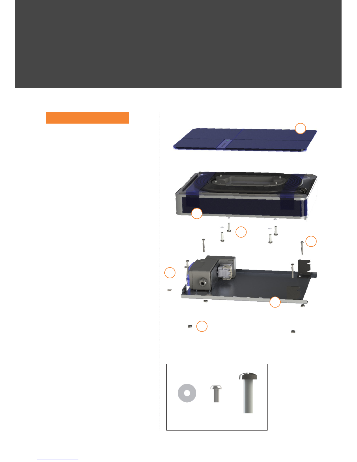
l Fig F2.1 shows an exploded view of
the product.
l The parts in fig F2.1 are identified as: -
1-0 Decorative Front Panel.
2-0 Back panel.
3-0 Control unit.
4-1 4 x decorative front panel
retention screws.
4-2 4 x back panel spacer washers.
4-3 2 x charger retention
tamperproof screws.
AS 4 x attachment screws.
QUICK OVERVIEW
Page 5
ANDERSEN
A1 INSTALLATION GUIDE
A
ANDERSEN
PAGE 5
1. SELECT THE INSTALLATION LOCATION
1.1 GENERAL CRITERIA FOR SELECTING
AN INSTALLATION SITE
The Andersen A1 has been
designed for indoor and outdoor
domestic use. If possible, install the
Andersen A1 so that it is protected
from direct rainfall and sunlight
to avoid the effects of weather,
such as icing, overheating, and
damage by hailstones or the like.
Ensure that you comply with the
permitted operating ambient
conditions. Ensure compliance
with local installation standards
and regulations. Ensure that the
proposed mounting surface is secure
and substantially vertical and flat,
take account of the weight of the
Andersen A1 at 15 Kg
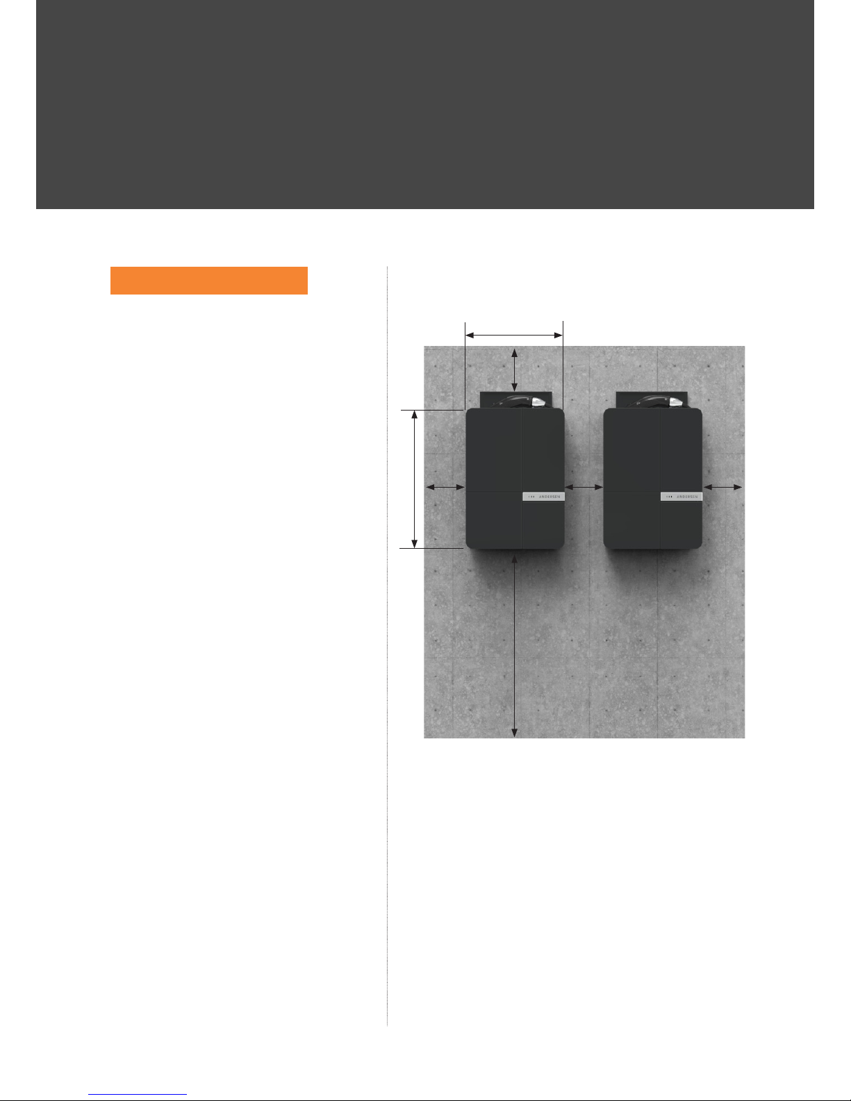
1.2 RECOMMENDED CLEARANCES
AROUND THE INSTALLED
ANDERSEN A1
See fig F3.1 for recommended
clearances around the installed
Andersen A1. Ease of winding
the charge cable into the A1
magic slots may be reduced if
the recommended clearances are
reduced. If two Andersen A1 units
are placed next to each other then
they can share the horizontal gap
between them. The working space
around the Andersen A1 can be the
mounting surface or open space.
The Andersen A1 can be placed
close to pipes, trunking and the like
providing they do not prevent easy
access and winding of the charge
cable in to the magic slots.
345mm (13”)
750mm (30”)
200mm
(8”)
200mm
(8”)
200mm
(8”)
200mm
(8”)
Fig F3.1
490mm (19”)
HOW TO INSTALL
Page 6
ANDERSEN
A1 INSTALLATION GUIDE
A
ANDERSEN
PAGE 6
2. INSTALL THE BACK PANEL
2.1 Screw the back panel to the
selected location
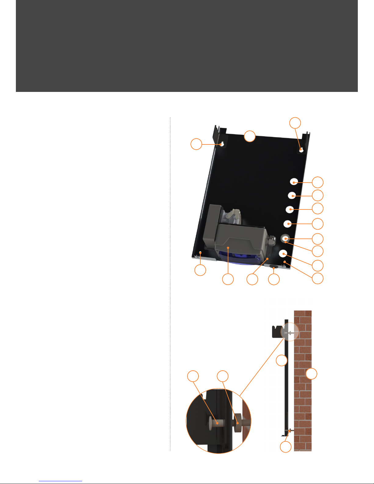
2.1.1 Determine where the cable entry
is to be positioned, there are 6
options in the rear of the back panel,
hole 2-B, 2-C, 2-D, 2-E, 2-F, 2-G.
and one in the bottom of the back
panel, hole 2-A see fig F4.1 Move
the cable entry bush 2-1-4 to the
selected hole.
2.1.2 Washers 4-2 are to be fitted
between the back panel and the
mounting surface M, behind each of
the mounting screw holes, these are
used to space the back panel from
the mounting surface. See fig F4.2
2.1.3 Attach the back panel to the
mounting surface using 4 screws
AS, (not supplied) ensuring that
the supply cable lines up with the
selected entry hole. The maximum
screw diameter that can be used
is 6mm. NOTE the weight of
the Andersen A1 is about 15 Kg
depending on the variant.
2.2 Wire the Back Panel to the mains
supply.
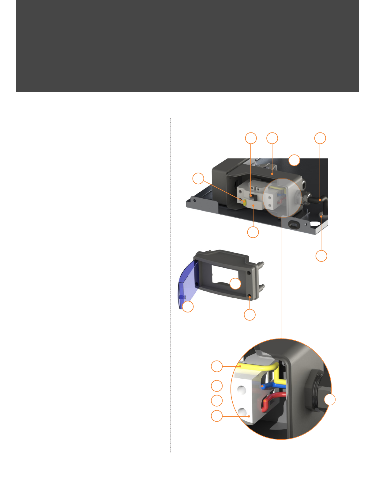
2.2.1 The RCD assembly 2-1 can be
removed for wiring if needed by
removing the 4 fixing screws 2-1-6
see fig F4.1
2.2.2 Open the RCD opening door
2-1-2, ensure that the RCD 2-1-5
is switched OFF using its switch 2-S
then remove the RCD front panel
2-1-1 by releasing its 4 x retention
screws 2-CS, see fig F4.1 and
fig F4.3
Fig F4.1
2-0
2-J
2-G
2-K
2-A2-1-6
2-K
2-1
2-E
2-1-4
2-F
2-C
2-D
2-B
2-H
x4
Fig F4.2
M
AS 4-2
4.2
2-0
x4
Page 7
ANDERSEN
A1 INSTALLATION GUIDE
A
ANDERSEN
PAGE 7
2.2.3 Feed the mains supply cable 2-M
through the selected hole on the
back panel.
2.2.4 Feed the mains supply cable
through the cable gland entry 2-1-3
and wire to the three terminals, L, N,
E as shown in fig F4.3. Ensure the
clamping screws are tight and the
cable gland is tight and sealed.
2.2.5 Carry out normal wiring safety
checks. Note the metal cabinet of
the Andersen A1 is NOT earthed.
2.2.6 Replace the RCD front panel.
2.2.7 Replace the RCD assembly if it was
removed for wiring.
2.2.8 Open the RCD door 2-1-2 to re
expose the RCD 2-1-5
2.2.9 Ensure that the RCD is still switched
OFF.
2.2.10 Ensure that the supply protective
cover 2-1-7 is in place. fig F7.1
2.2.11 Turn on the mains supply.
2.2.12 Turn the RCD ON using switch 2-S
and ensure that it stays ON fig F4.3
2.2.13 Push the RCD test button 2-T and
ensure that the RCD turns OFF fig
F4.3
2.2.14 Repeat the previous 2 items one
more time.
2.2.15 Leave the RCD turned OFF and
turn OFF the mains supply at the
consumer unit.
2.2.16 Close the RCD opening door.
Fig F4.3
2-12-S
2-T
2-1-2
2-1-3
2-1-5
2-1-1
2-CS
2-1-5
2-0
2-M
2-1-4
x4
E
N
L
Page 8
ANDERSEN
A1 INSTALLATION GUIDE
A
ANDERSEN
PAGE 8
3. CHECK THE SETTINGS ON THE
A1 CHARGER CONTROLLER
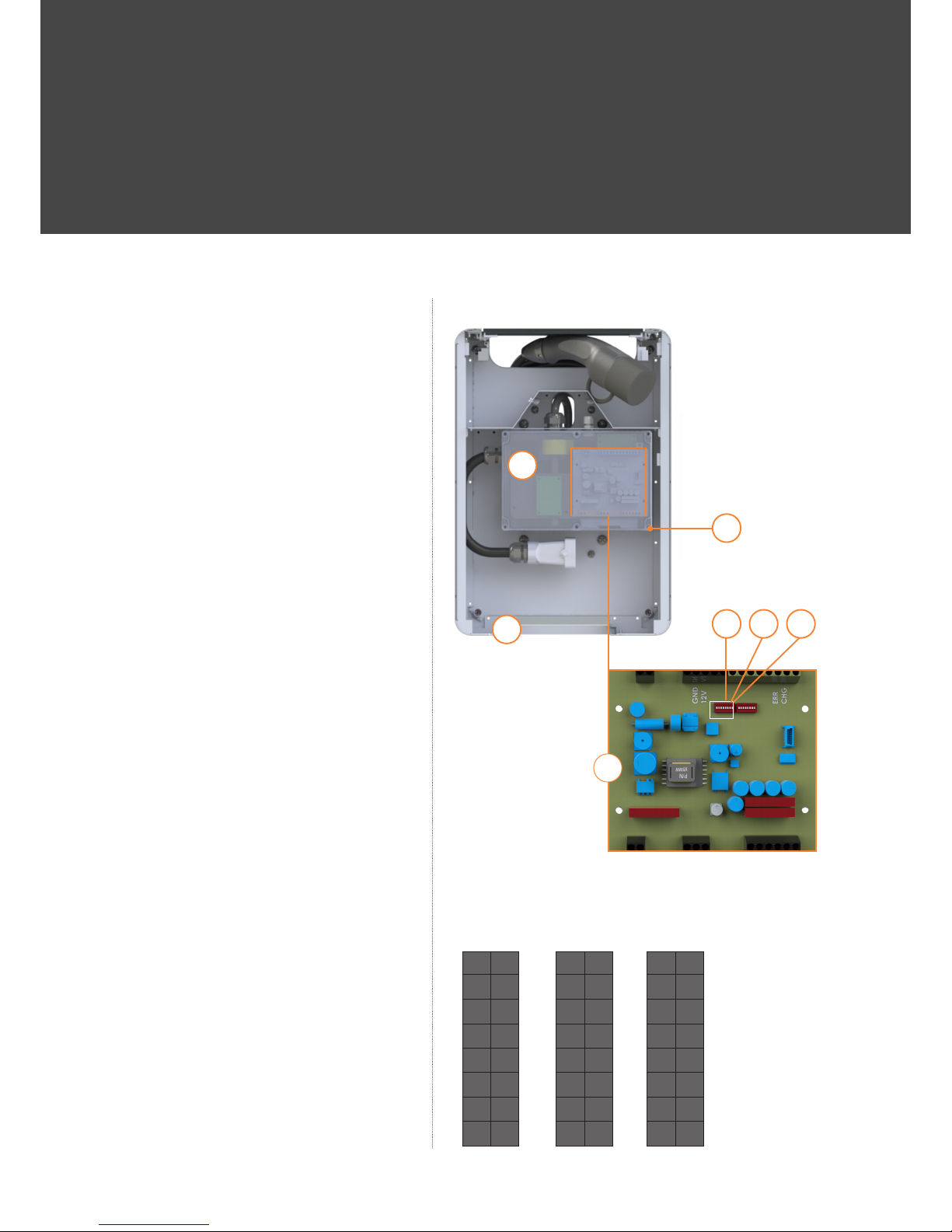
3.1 The Andersen A1 charger controller
supplied set to charge at 32 Amps
maximum.
3.2 The Andersen A1 can be re set to a
maximum charge current of 20 Amps
or 16 Amps.
3.3 To change the maximum
charge current: -
3.3.1 Place the Andersen A1
control unit on a suitable
soft flat surface such as
cardboard with the sealed
control enclosure 3-1 facing
up fig F5.1
3.3.2 Remove the control
enclosure lid by removing its
retention screws 3-1-1.
Take great care not to
damage the delicate parts
inside the enclosure.
3.3.3 Identify the main control
PCB 3-1-2 and the dual in
line switch S1 on that PCB.
3.3.4 Using a small screwdriver
carefully set the switches
on S1 according to those
shown in Table T5.2 for the
required maximum current.
3.3.5 Replace the enclosure lid
and fixing screws, ensuring
that the sealing gasket is
correctly positioned.
O
X
X
X
X
O
X
X
O
X
X
X
O
X
X
X
O
X
X
X
O
O
X
X
1
2
3
4
5
6
7
8
1
2
3
4
5
6
7
8
1
2
3
4
5
6
7
8
32 Amp 20 Amp 16 Amp
Table T5.2
Switch settings for S1
Fig F5.1
3-1
3-0
3-1-1
3-1-2
3-0S11
x4
Page 9
ANDERSEN
A1 INSTALLATION GUIDE
A
ANDERSEN
PAGE 9
4. FIT THE DECORATIVE FRONT PANEL TO
THE CONTROL UNIT
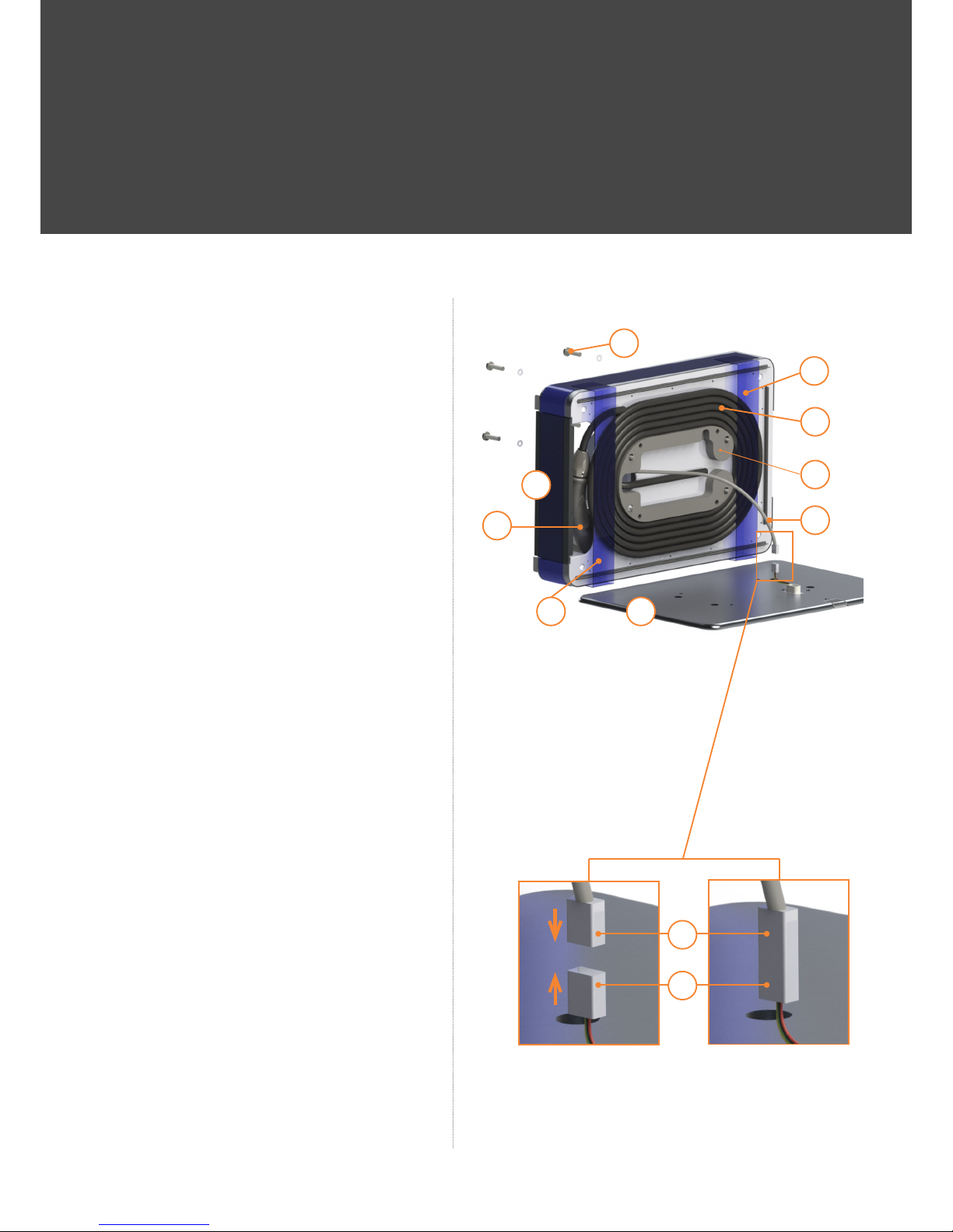
4.1 Lay decorative front panel 1-0 on a soft
horizontal surface such as cardboard
with the front side down and the control
unit 3-0 on its side as shown in fig F6.1
4.2 Ensure vehicle charging cable 3-9 is
flat and has no overlaps as shown in
fig F6.1 The charging cable is held
in place by the retaining film 3-8. If
the charging cable is not correctly
positioned, then, either correct its
position OR remove the entire length
of cable and exit the cable from the
bottom of the control unit. To unwind
the cable, it is necessary to remove
the protective film from the top of the
control unit to enable the top chamber
door 3-4 to be opened and allow
removal of the vehicle charge socket
3-5. Close the top chamber door after
removing the vehicle charge socket.
4.3 Connect the led socket 3-7 to the led
plug 1-3 see fig F6.1.1 and F6.1.2,
ensure the correct rotation of the
connector and that the two parts are
latched together.
4.4 Locate the led cable 3-10 on the rear
side of the control unit, this is the side
where the screws 4-1 are shown on fig
F6.1. Gently pull the led cable at the
same time as lowering the control unit
on to the front panel. Locate the 4 x
front panel fixing screws through the
control unit and in to the decorative
front panel, hand tighten. Check that
the led cable is not trapped between
the front panel and the control unit,
the led cable must not be visible in any
of the 4 cable magic slots. Tighten the
front panel fixing screws.
4.5 Put the assembly to the side and in a
safe place ready for wall mounting.
Fig F6.1
Fig F6.1.1 Fig F6.1.2
3-4
4-1
3-9
3-8
3-0
3-10
1-0
3-5
3-8
x4
3-7
1-3
Page 10
ANDERSEN
A1 INSTALLATION GUIDE
A
ANDERSEN
PAGE 10
5. FIT THE CONTROL UNIT
TO THE BACK PANEL
5.1 Ensure that mains supply is OFF
and that the RCD is OFF.
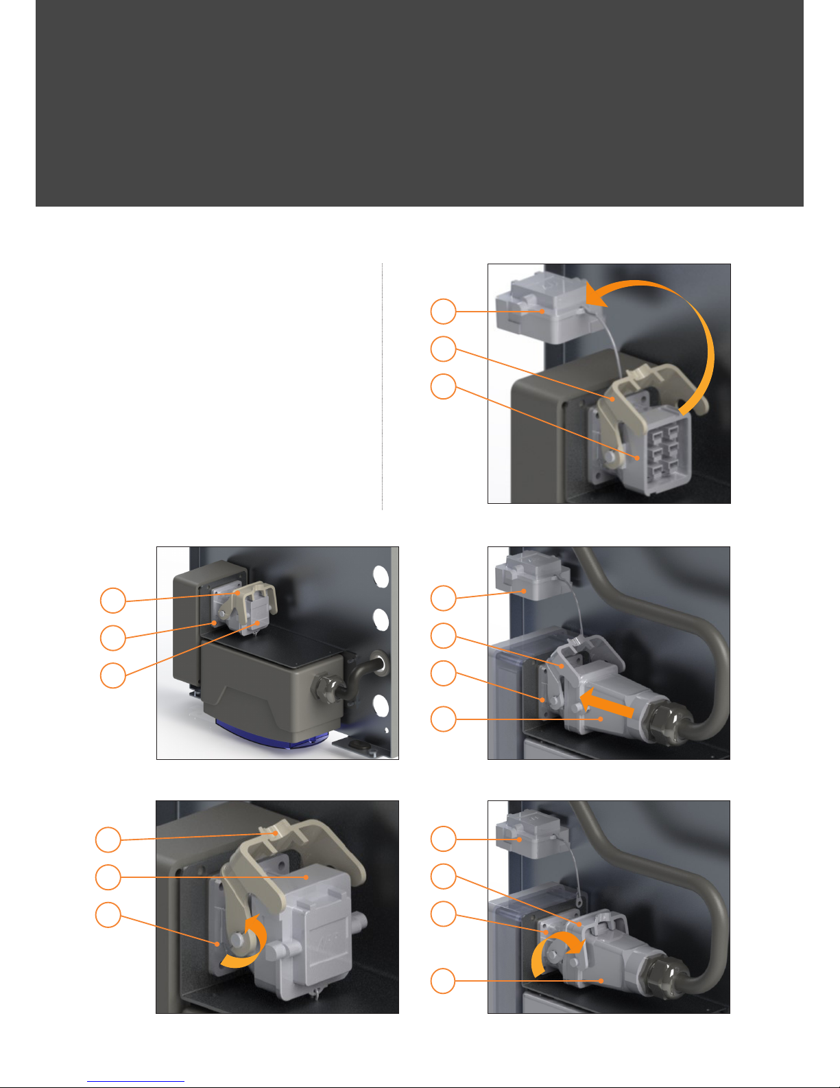
5.2 Locate the mains socket 2-1-9 and
the cam lock 2-1-8 on the back
panel, see fig F 7.1
5.3 Rotate the cam upwards to its full
extent of movement see fig F7.2
5.4 Remove the protective cover 2-1-7
and place behind the socket see
fig F7.3
Fig F7.1
Fig F7.2
Fig F7.3
2-1-8
2-1-8
2-1-7
2-1-9
2-1-7
2-1-8
2-1-7
2-1-9
2-1-9
Fig F7.4
Fig F7.5
2-1-7
2-1-7
2-1-8
2-1-8
2-1-9
2-1-9
3-2
3-2
Page 11
ANDERSEN
A1 INSTALLATION GUIDE
A
ANDERSEN
PAGE 11
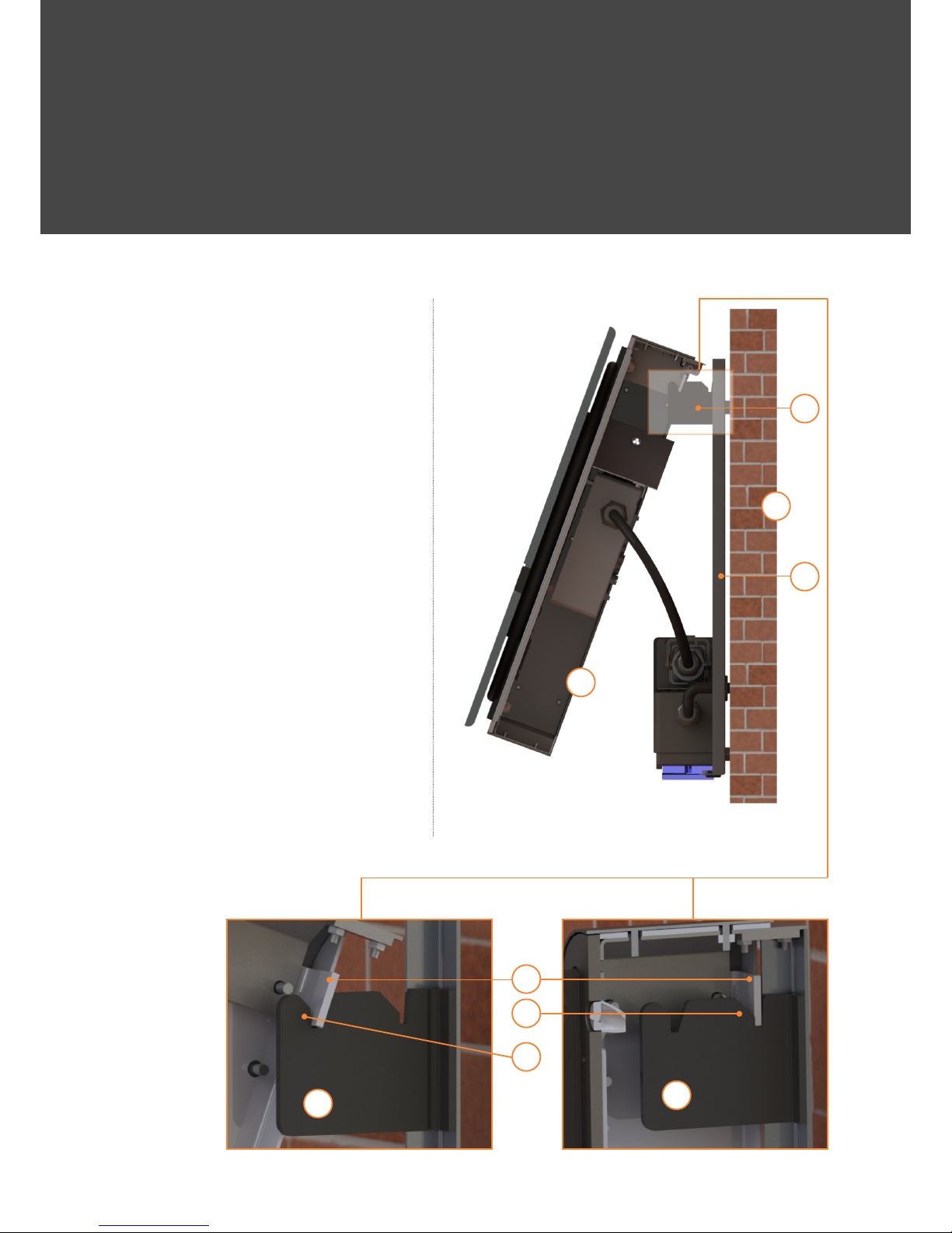
5.5 locate the two fixing lugs 3-3 on
the control unit and the hanging
brackets 2-2 on the back panel see
fig F7.6
5.6 Offer up the control unit to the back
panel and locate the two hanging
brackets in the two front slots 2-FS
see fig F7.6.1 Let the hanging
brackets take the weight of the
control unit and carefully pull the
bottom of the control unit out away
from the wall as far as it will go, take
care not to damage the top rear of
the control unit by engagement with
the wall see fig F7.6
5.7 Insert the control unit mains plug 3-2
into the mains socket 2-1-9 ensuring
that it is in the correct rotation see
fig F7.4
5.8 Rotate the cam lock item 2-1-8 to
lock the plug in position see fig F7.5
Fig F7.6
Fig F7.6.1 Fig F7.6.2
M
2-0
2-2
3-0
2-RS
2-FS
2-2
2-2
3-3
Page 12
ANDERSEN
A1 INSTALLATION GUIDE
A
ANDERSEN
PAGE 12
Fig F7.7
Fig F7.8
4-3
3-5
3-4
3-6
x2
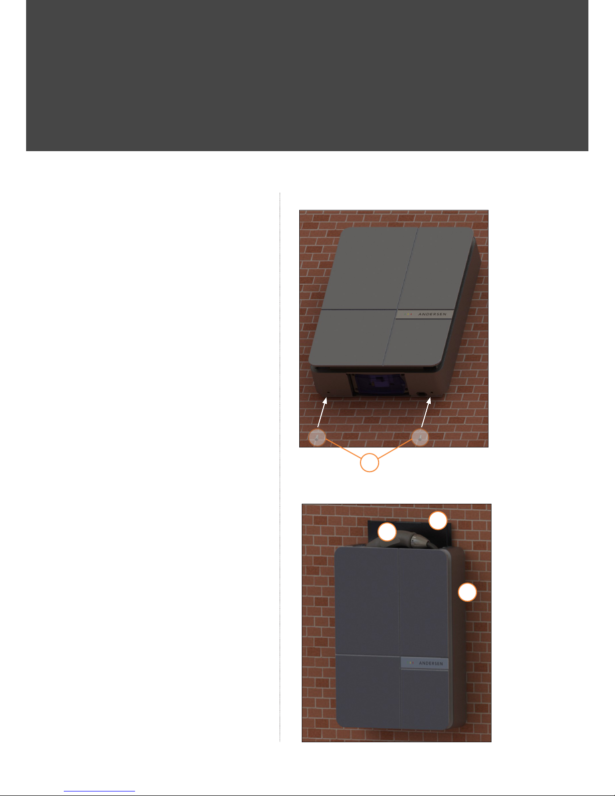
5.9 Rotate the control unit until it is
almost vertical and lift it up just
enough to release the lugs from
their locations in the two front slots
2-FS and then move the control unit
back towards the wall to re-locate
the two lugs in the two rear slots
2-RS. Allow the control unit to hang
freely see fig F7.6.2
5.10 Push the bottom of the Andersen A1
unit towards the wall and fit the two
anti-tamper retaining screws 4-3 to
the bottom of the control unit see
fig F7.7. Remove any protective film
covering the holes in the control
unit before tightening the retaining
screws.
5.11 Remove all the protective films 3-8
from the outer panels. Remove the
horizontal strips of plastic film that
hold the charging cable in place.
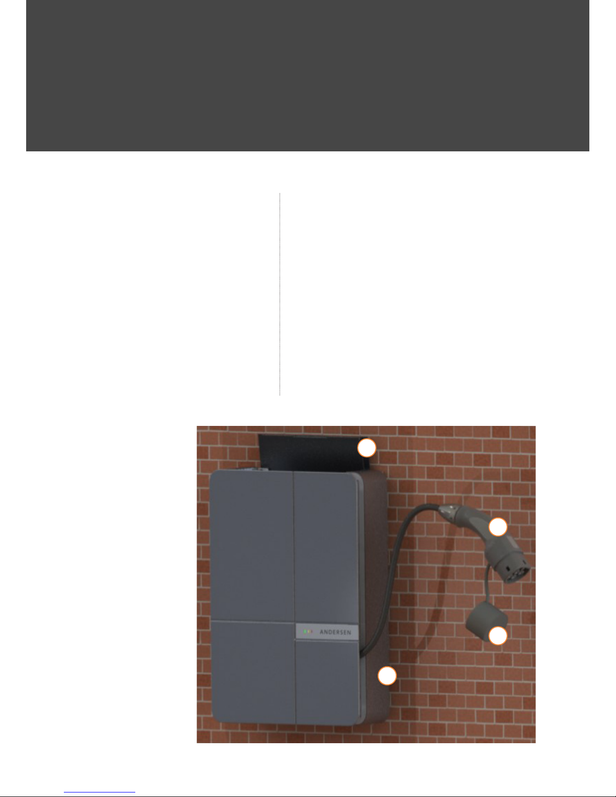
5.12 If the charging cable has not been
removed from the magic slots then
open the top chamber door 3-4 and
remove the vehicle charging socket
item 3-5, fig F7.8 and F7.9
Page 13
ANDERSEN
A1 INSTALLATION GUIDE
A
ANDERSEN
PAGE 13
5.13 Unwind all the cable from the
magic slots 3-6, fig F7.9
5.14 Rewind the cable in to the magic
slots 3-6 It can be rewound
clockwise or anticlockwise to suit
the client. Put the vehicle socket
back in the top chamber and close
the top chamber door.
5.15 Turn on the mains electric supply at
the consumer unit.
5.16 Open the RCD opening door
2-1-2 and turn on the RCD, check
that the green mains ON LED is
illuminated on the front panel.
Close the RCD opening door
5.17 Open the top chamber door, check
that the 4 cable magic slots and
the top chamber are illuminated. In
bright ambient lighting conditions,
it may be necessary to shade the
Andersen A1 to see the illuminated
parts.
5.18 Carry out a system check, check
that the front panel LEDs illuminate
at the correct times.
5.19 Replace the vehicle socket in the
top chamber and close the top
chamber door, have a cup of tea
and sign the job off.
3-5
3-11
3-4
3-6
Fig F7.9
Page 14

ANDERSEN
A1 INSTALLATION GUIDE
A
ANDERSEN
PAGE 14
DESCRIPTION OF PARTS
1-0 Decorative front panel
1-1 Metal Decorative front panel
1-2 Wood Decorative front panel
1-3 LED plug
2-0 Back panel
2-1 RCD assembly
2-1-1 RCD front panel
2-1-2 RCD opening door
2-1-3 Cable entry bush to RCD assembly
2-1-4 Back panel cable bush
2-1-5 RCD
2-1-6 RCD assembly fixing screws (x4)
2-1-7 Supply protective cover
2-1-8 Cam lock
2-1-9 Mains Socket
2-2 Hanging bracket (x2)
2-A Bottom cable entry
2-B Rear cable entry bottom
2-C Rear cable entry
2-D Rear cable entry
2-E Rear cable entry
2-F Rear cable entry
2-G Rear cable entry top
2-H Top fixing hole
2-J Top fixing hole
2-K Bottom fixing hole
2-L Bottom fixing hole
2-M Mains supply cable, not supplied
with conductors: -
L Live
N Neutral
E Earth
2-FS Front slot for hanging control unit
2-RS Rear slot for hanging control unit
2-AS Back panel attachment screw, 4 off
2-T RCD test button
2-S RCD ON / OFF switch
2-CS RCD front panel fixing screws.
3-0 Control unit
3-1 Sealed control enclosure
3-1-1 Sealed control enclosure lid screws (x6)
3-1-2 Main control Printed Circuit Board.
3-2 Control unit mains plug
3-3 Fixing lug
3-4 Top chamber door
3-5 Vehicle charging socket x2
3-6 Magic slots
3-7 LED socket
3-8 Protective film
3-9 Vehicle charging cable
3-10 LED cable
4-0 Accessory pack
4-1 Decorative front panel retention
screws (x4)
4-2 Back panel spacer washers (x4)
4-3 Anti-tamper retaining screws (x2)
5-0 Other Parts
A Large packing box
B Small packing box for decorative
front panel.
M Mounting surface for Control unit
Andersen EV
London, UK
www.andersen-ev.com
Original installation instructions
Copyright ©2017 Andersen EV UK
This documentation contains information protected by copyright.
All rights reserved, especially the right of reproduction and distribution.
No part of this documentation may be reproduced (photocopying, scanning
or any other procedures) or processed, copied or distributed in any form
using electronic systems without the written consent of Andersen EV.
Contraventions are liable to compensation.
 Loading...