

Page 1

MODEL:
WPL430 & WPL436
IMPORTANT SAFETY INSTRUCTIONS
Carefully read the following important information regarding
2017-03-13 MAAN1174-01
installation safety and maintenance.
Keep these instructions for future reference.
Page 2
IMPORTANT SAFETY NOTICE
2
READ AND SAVE THESE INSTRUCTIONS
READ ALL INSTRUCTIONS BEFORE INSTALLING AND OPERATING THIS APPLIANCE
● The installation in this manual is intended for qualified installers, service technicians or persons
with similar qualified background. Installation and electrical wiring must be done by qualified
professionals and in accordance with all applicable codes and standards, including fire-rated
construction.
● Range hood may have very sharp edges; please wear protective gloves if it is necessary to
remove any parts for installing, cleaning or servicing.
● Activating any switch ON before completing installation may cause ignition or an explosion.
● Due to the size and weight of this range hood, two people installation is recommended.
To reduce the risk of fire, electric shock, or injury to persons:
● For general ventilating use only. DO NOT use to exhaust hazardous or explosive materials
and vapors.
• WARNING: to Reduce The Risk Of Fire Or Electric Shock, Do Not Use This Fan With Any
Solid-State Speed Control Device
● The combustion air flow needed for safe operation of fuel-burning equipment may be affected
by this unit’s operation. Follow the heating equipment manufacturer’s guideline and safety
standards such as those published by the National Fire Protection Association (NFPA), and the
American Society of Heating, Refrigeration and Air Conditioning Engineers (ASHRAE), and
other local code authorities.
● Before servicing or cleaning unit, unplug and disconnect the hood from the power supply.
● Clean grease laden surfaces frequently. To optimize performance and to disperse air properly,
make sure to vent air outside. DO NOT vent exhaust into spaces between walls, crawl spaces,
ceiling, attics or garages.
● Ducted fans MUST always be vented to the outdoors.
● This unit MUST be grounded and use only metal ductwork.
● Sufficient air is needed for proper combustion and exhausting of gases through the duct to
prevent back drafting.
● When cutting or drilling into wall or ceiling, be careful not to damage electrical wiring or other
hidden utilities.
● All electrical wiring must be properly installed, insulated and grounded.
● Old duct work should be cleaned or replaced if necessary to avoid the possibility of a grease fire.
● Check all joints on duct work to ensure proper connection and all joints should be properly
taped.
● Use this unit only in the manner intended by the manufacturer. If you have questions, contact
the vendor.
Page 3
IMPORTANT SAFETY NOTICE
3
READ AND SAVE THESE INSTRUCTIONS
READ ALL INSTRUCTIONS BEFORE INSTALLING AND OPERATING THIS APPLIANCE
WARNING: TO REDUCE RISK OF A RANGE TOP GREASE FIRE:
a) Never leave surface units unattended at high settings. Boilovers cause smoking and greasy
spillovers that may ignite. Heat oils slowly on low or medium settings.
b) Always trun hood ON when cooking at high heat or when flambeing food (i.e. Crepes Suzette,
Cherries Jubilee, Peppercorn Beef Flambé).
c) Clean ventilating fans frequently. Grease should not be allowed to accumulate on fan or filter.
Before servicing or cleaning unit, unplug and disconnect the hood from the power supply.
d) Use proper pan size. Always use cookware appropriate for the size of the surface element.
WARNING: TO REDUCE RISK OF INJURY TO PERSONS IN THE EVENT OF A
RANGE TOP GREASE FIRE, OBSERVE THE FOLLOWING :
a
a) SMOTHER FLAMES with a close-fitting lid, cookie sheet, or metal tray, then turn off the
burner. BE CAREFUL TO PREVENT BURNS. If the flames do not go out immediately,
EVACUATE AND CALL THE FIRE DEPARTMENT.
b) NEVER PICK UP A FLAMING PAN - You may be burned.
c) DO NOT USE WATER, including wet dishcloths or towels - a violent steam explosion will
result.
d) Use an extinguisher ONLY if:
1) You know you have a Class A, B, C extinguisher, and you already know how to operate it.
2) The fire is small and contained in the area where it is started.
3) The fire department is being called.
4) You can fight the fire with your back to an exit.
a
Based on “Kitchen Firesafety Tips” published by NFPA.
To reduce the risk of injury to persons in the event of a gas leaks:
● Extinguish any open flame.
● DO NOT turn on the lights or any type of appliance.
● Open all doors and windows to disperse the gas. If you still smell gas, call the gas
company and fire department.
Your safety and the safety of others is very important. We have provided many important safety
messages in this manual and on your appliance. Always read and obey all safety messages. All safety
messages will tell you what the potential hazard is, tell you how to reduce the chance of injury, and tell
you what can happen if the instructions are not followed.
Page 4
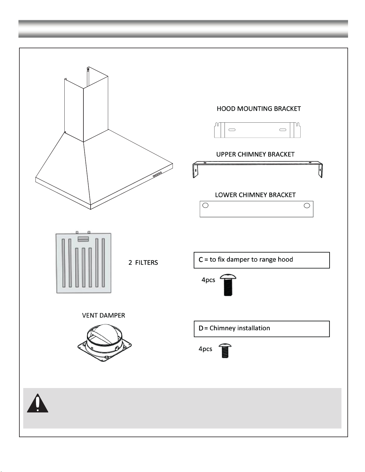
PARTS SUPPLIED:
4
Hardware Note: For safety reasons, range hood mounting screws and anchors will not be
included due to the variation of cabinetry constructions and wall material. Please consult your
installation specialist regarding the optimal type of mounting screws and wall anchors to suit
your home’s construction.
Page 5
VENTING REQUIREMENTS: HEIGHT & CLEARANCE:
5
• Vent system must terminate to the outside
(Roof or side wall).
• DO NOT terminate the vent system in an attic
or other enclosed area.
• DO NOT use 4” (10.2 cm) laundry-type wall
caps.
• Use metal/aluminum vent only. Rigid metal/
aluminum vent is recommended.
• DO NOT use plastic vent.
• Always keep the duct clean to ensure proper
airflow.
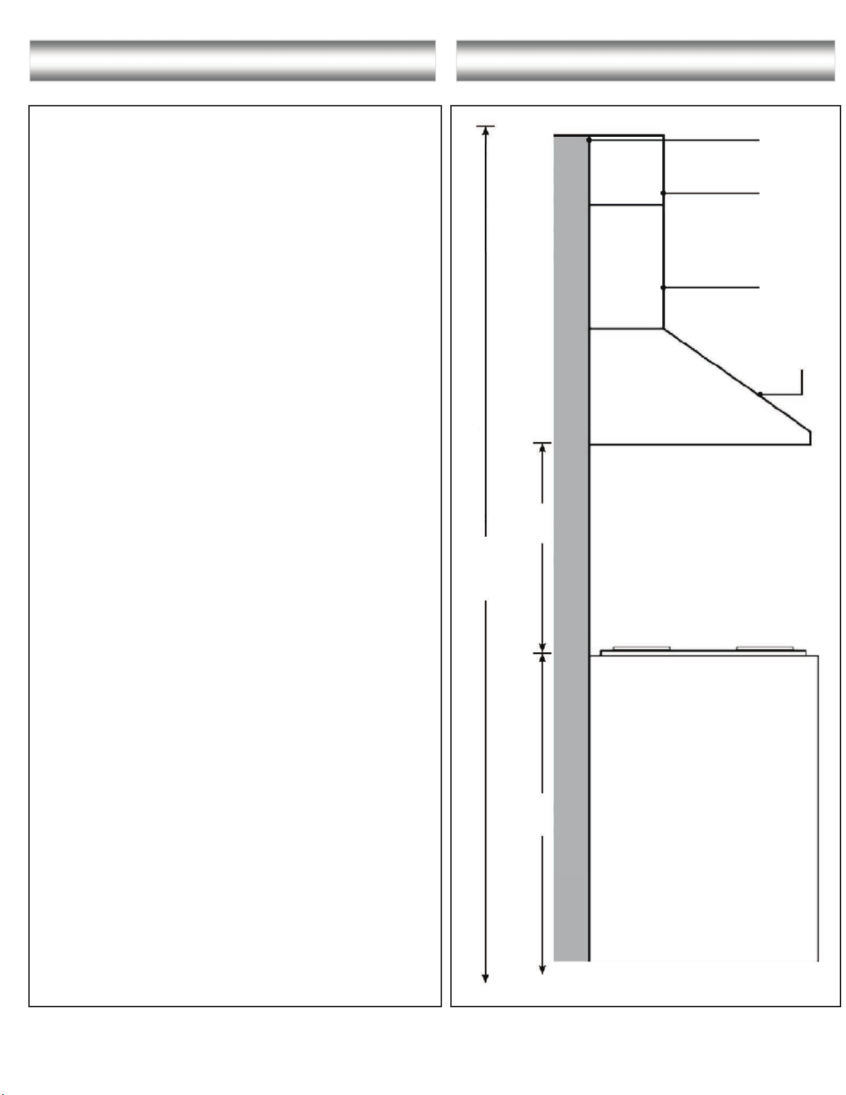
• Calculate the following figures before
installation:
1. Distance from the floor to the ceiling
2. Distance between the floor to the
countertop/stove
3. Distance between the cooking surface to
the range hood (recommend 24” to 30”)
minimum of 30” is required for gas cook top
4. Height of hood and duct cover
For the most efficient & quiet operation:
• A distance of 24” to 30” is recommended
between stove top and the bottom of range
hood. 30” minimum is required for gas stove tops.
• It is recommended that the range hood be
vented vertically through the roof through 6”
(15.3 cm) or bigger round metal/aluminum
vent work.
• The size of the vent should be uniform.
• Use no more than three 90° elbows.
• Make sure there is a minimum of 24” (61 cm) of
straight vent between the elbows if more than one
elbow is used.
• DO NOT install two elbows together.
• The length of vent system and number of elbows
should be kept to a minimum to provide efficient
performance.
• The vent system must have a damper. If roof or
wall cap has a damper, DO NOT use damper (if
supplied) on top of the range hood.
• Use silver tape or duct tape to seal all joints in the
vent system.
• Use caulking to seal exterior
around the cap.
wall or roof opening
Can reach
9’ ceiling
if installed
at 31” from
cooktop.
26” - 41 3/8”
(66 cm -105 cm)
Max:
108.85”
Chimney mounting bracket
Upper chimney
Lower chimney
Range hood
Min: 24”
Max: 30”
Countertop / Stove
Page 6

IMPORTANT:
6
• A minimum of 6” round or 3-1/4 x 10” rectangular duct (purchased separately) must be used to
maintain maximum airflow efficiency.
• Always use rigid type metal/aluminum ducts if available to maximize airflow when connecting to
provided duct.
• Please use Duct Run Calculation below to compute total available duct run when using elbows,
transitions and caps.
• ALWAYS, when possible, reduce the number or transitions and turns. If long duct run is required,
increase duct size from 6” to 7” or 8”. If a reducer is used, install a long reducer instead of a pancake
reducer. Reducing duct size will restrict airflow and decrease airflow, thus reduce duct size as far
away from opening as possible.
• If turns or transitions are required, install as far away from opening and as far apart, between two
(2), as possible.
• Minimum mount height between stove top to hood bottom should be no less than 24-inch for
electric cook tops and minimum of 30-inch for gas stove tops and no higher than 30-inch for electric
cook tops.
• It is important to install the hood at the proper mounting height. Hoods mounted too low could result
in heat damage and fire hazard; while hoods mounted too high may be hard to reach and will lose its
performance and efficiency.
• If available, also refer to stove top manufacturer’s height clearance requirements and recommended
hood mounting height above range.
CALCULATING VENT SYSTEM LENGTH:
To calculate the length of the system you need, deduct the equivalent feet for each vent piece used in the
system from the recommended maximum duct run.
Duct Run Calculation example:
One roof cap, two 90º elbows, and one 45º
elbow use
0ft + 9ft + 9ft + 5ft = 23ft used.
Deduct 23ft from 30ft, 7ft maximum
available for straight duct run.
-
Page 7
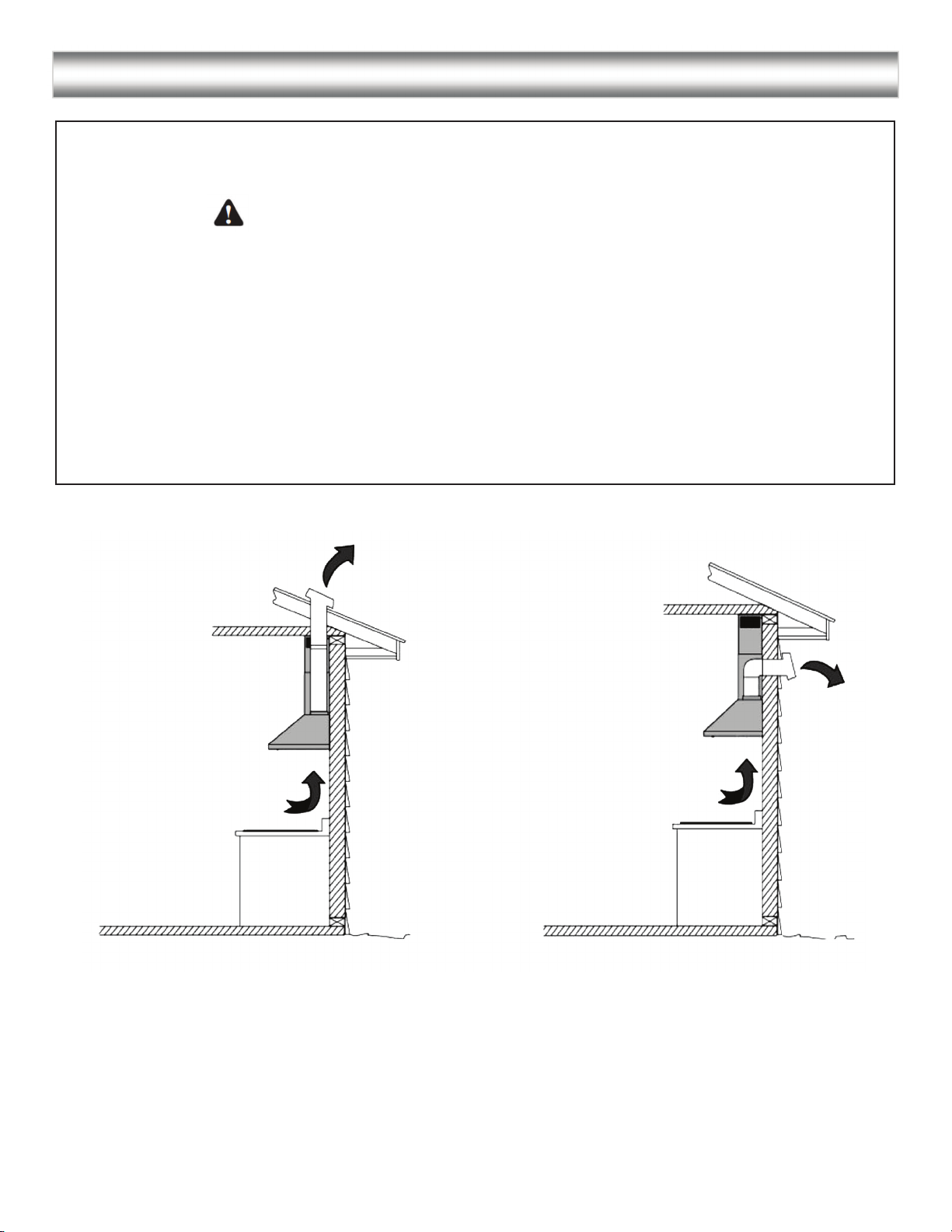
VENTING METHODS:
7
• This range hood is factory set for venting through the roof or wall.
• Vent work can terminate either through the roof or wall. To vent through a wall, a 90° elbow is needed.
IMPORTANT:
NEVER exhaust air or terminate duct work into spaces between walls, crawl spaces, ceiling,
•
attics or garages. All exhaust must be ducted to the outside.
•
Fasten all connections with sheet metal screws and tape all joints with certified aluminum or foil tape.
•
WARNING - TO REDUCE RISK OF FIRE, USE METAL/ALUMINUM DUCT WORK ONLY
Please check the building codes in your city to learn which tape product is recommended
•
Use caulking to seal exterior wall or roof opening around the cap.
TOP VENTING WALL EXHAUSTTOP VENTING ROUGH EXHAUST
Page 8
ELECTRICAL REQUIREMENTS:
8
IMPORTANT:
Observe all governing codes and ordinances.
It is the customer’s responsibility to contact a qualified electrical installer.
If codes permit and a separate ground wire is used, it is recommended that a qualified electrician determine
that the ground path is adequate.
A 120-Volt, 60 Hz, AC-only, fused electrical supply is required on a separate 15-amp circuit, fused on both
sides of the line.
DO NOT ground to a gas pipe.
Check with a qualified electrician if you are not sure that the range hood is properly grounded.
DO NOT have a fuse in the neutral or ground circuit.
IMPORTANT: Save this Installation Guide for electrical inspector’s use.
The range hood must be connected with copper wire/plug only.
The range hood should be connected directly to the fused disconnect (or circuit breaker) box through
flexible armored or non-metallic sheathed copper cable. UL/CSA listed strain relief must be provided at
each end of the power supply cable.
Use only with range hood cord-connection kits that have been investigated and found acceptable for use
with this model.
GROUNDING INSTRUCTIONS
This appliance must be grounded. In the event of an electrical short-circuit, grounding reduces the risk of
electric shock by providing an escape wire for the electric current. This appliance is equipped with a cord
having a grounding wire with a grounding plug. The plug must be plugged into an outlet that is properly
installed and grounded.
WARNING - Improper grounding can result in a risk of electric shock.
Consult a qualified electrician if the grounding instructions are not completely understood, or if doubt exists
as to whether the appliance is properly grounded. DO NOT use an extension cord. If the power supply cord
is too short, have a qualified electrician install an outlet near the appliance.
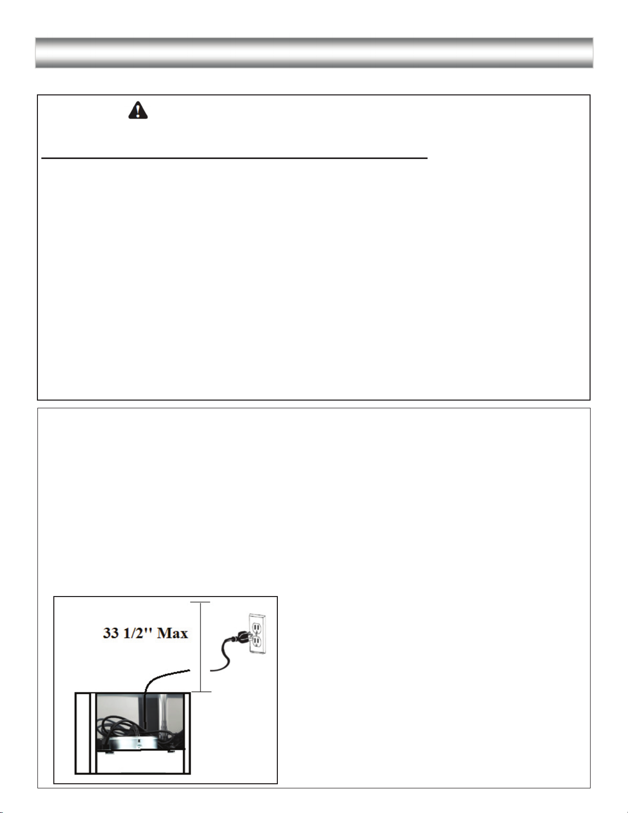
Place the outlet at a maximum distance of 33
1/2” from where the cord exits on the hood
Page 9
PREPARATIONS:
9
Advanced Preparations:
• Be familiar with the controls of the range hood by reading through Range Hood Operations, Page 13.
• Place the range hood on a flat, stable surface. Connect the range hood to a designated standard outlet
(120-Volt, 60Hz, AC only) and turn on the range hood. Verify all operations of the range hood by
referring to Range Hood Operations.
• Place all supplied parts and required hardware on a flat, stable surface and verify the existence of all
supplied parts listed on Page 4.
Preparations:
NOTE: To avoid damage to your hood, prevent debris from entering the vent opening.
• Determine and mark the center line on the ceiling or wall where the range hood will be installed.
Make sure there is proper clearance within the ceiling or wall for exhaust vent.
• Due to the weight and size of this unit, please make sure that the support system or framework being
used is stable and secure in the ceiling or wall.
• Put a thick, protective covering over counter top, cook top or range to protect from damage or dirt.
Remove any hazardous objects around the area when installing.
CAUTION
If moving the cooking range is necessary to install the hood, turn OFF the power on an electric range at
the main electrical box. SHUT OFF THE GAS BEFORE MOVING A GAS RANGE
Page 10
INSTALLATION:
10
Installations (refer to Page 4 for parts):
NOTE: Use threaded drywall anchors only when
mounting the hood on sheet rock. Mounting
the hood on wall studs or lumbars is highly
recommended.
Hardware Note: For safety reasons, range hood mounting screws and anchors will not be
included due to the variation of cabinetry constructions and wall material. Please consult your
installation specialist regarding the optimal type of mounting screws and wall anchors to suit
your home’s construction.
Step 1: Measuring
• Measure the distance between stove top and the bottom of range hood. A distance of 24” to 30” is
recommended with a minimum of 30” for gas stove tops.
• To reach 9ft ceiling make sure hood is installed at 31” from cooking surface
• If you require longer chimney flue to reach your ceiling please contact vendor.
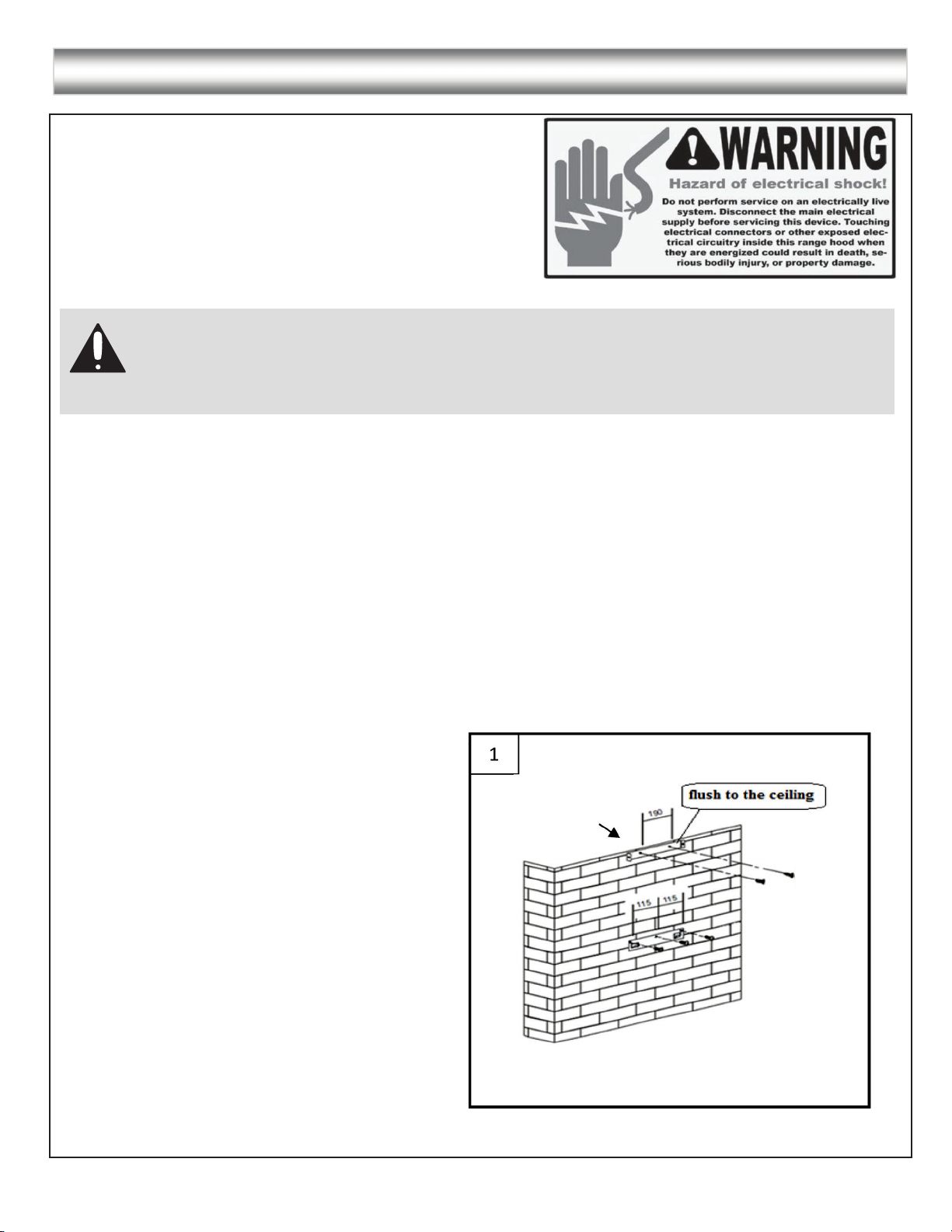
Step 2: Installing the hood mounting bracket
The range hood will be installed on top of this bracket.
•
(See Figure # 1)
• Using references in Height & Clearance on Page 5 and Measurements and Diagrams on Page 16,
Drill 3 holes that will be used to fix the lower mounting bracket.
Step 3: Installing upper chimney bracket
• Drill 2 holes according to the size of the upper
mounting bracket. The upper mounting bracket
should be positioned flush with the top of the
outside chimney (See Figure # 1)
•
Screw upper and hood mounting brackets in
tightly.
Page 11
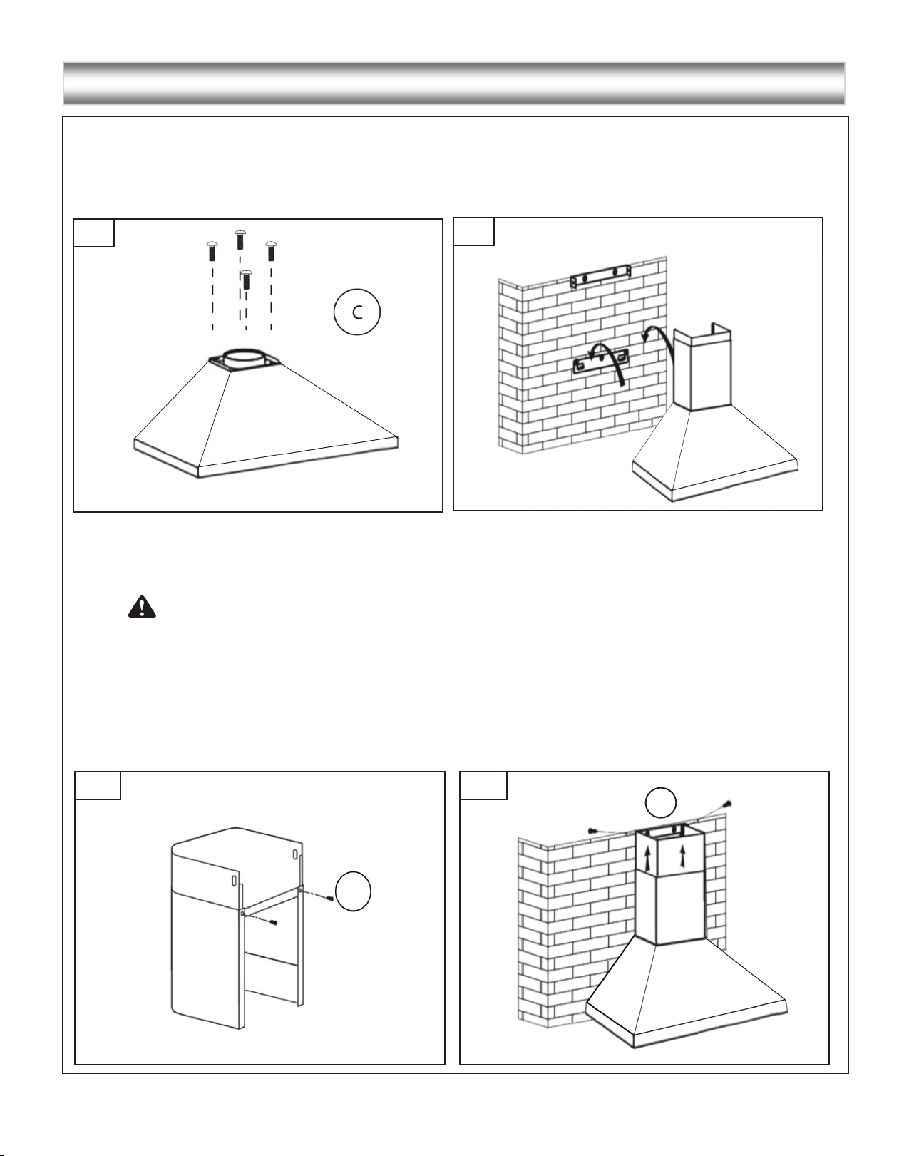
INSTALLATION CONTINUE:
11
Step 4: Venting
• Fix the damper on the top vent of hood with 4 screws (requires screw C).
If ventilation system is equipped with an external air duct with a different diameter, apply a reduction fitting.
However, for maximum performance and safety, a 6” round ducting is recommended. (See Figure # 2)
2
3
Step 5: Mounting the hood on the wall
• Hang the range hood on the hooks of the lower mounting bracket. (See Figure # 3)
Screw the range hood to the wall.
•
CAUTION - Make certain the range hood is secure before releasing!
• Remove the protective coating from the inner chimney. Carefully slide the inner chimney down into the
outer chimney.
• Use 2 screws (requires screw D) to fix the two chimneys together with the lower chimney bracket,
make sure inside chimney is moving freely. (See Figure # 4)
• Screw the inner chimney to the upper mounting bracket (requires screw D). (See Figure # 5)
• Connect the duct to the damper / duct connector and seal with duct tape.
• Connect the range hood to a designated standard outlet (120-Volt, 60 Hz, AC only).
4 5
D
D
Page 12
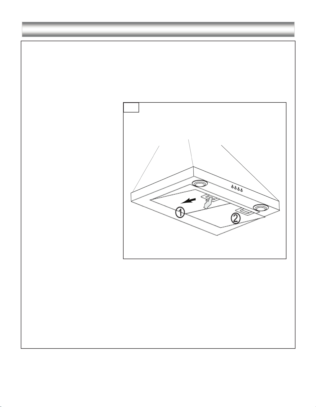
INSTALLATION CONTINUE:
12
Step 6: Installing filters
• To install filters for the following four steps (See Figure # 6):
- Angle the filter into slots at the back of the hood.
- Push the button on handle of the filter.
- Release the handle once the filter fits into a resting position.
- Repeat to install all filters.
6
Step 7: Test hood
• Turn power On in control panel.
• Check all lights and fan operations.
• Make sure to leave this Installation Manual for the homeowner.
Page 13
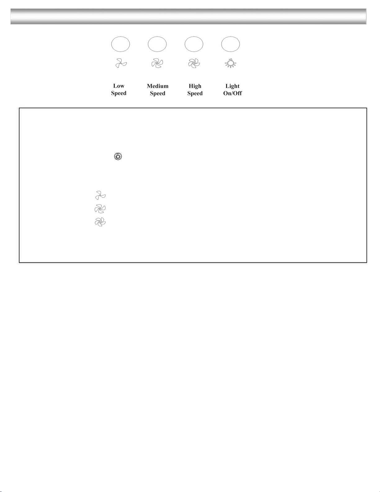
CONTROL PANEL OPERATION:
13
Control Panel Layout and Buttons Configurations:
Lights:
Press the light button to turn LED lights on and off.
Power Settings:
Press the
once the motor starts to operate at low speed.
Press the
Press the
again and the motor will reach medium speed.
again and the motor will reach high speed.
Page 14
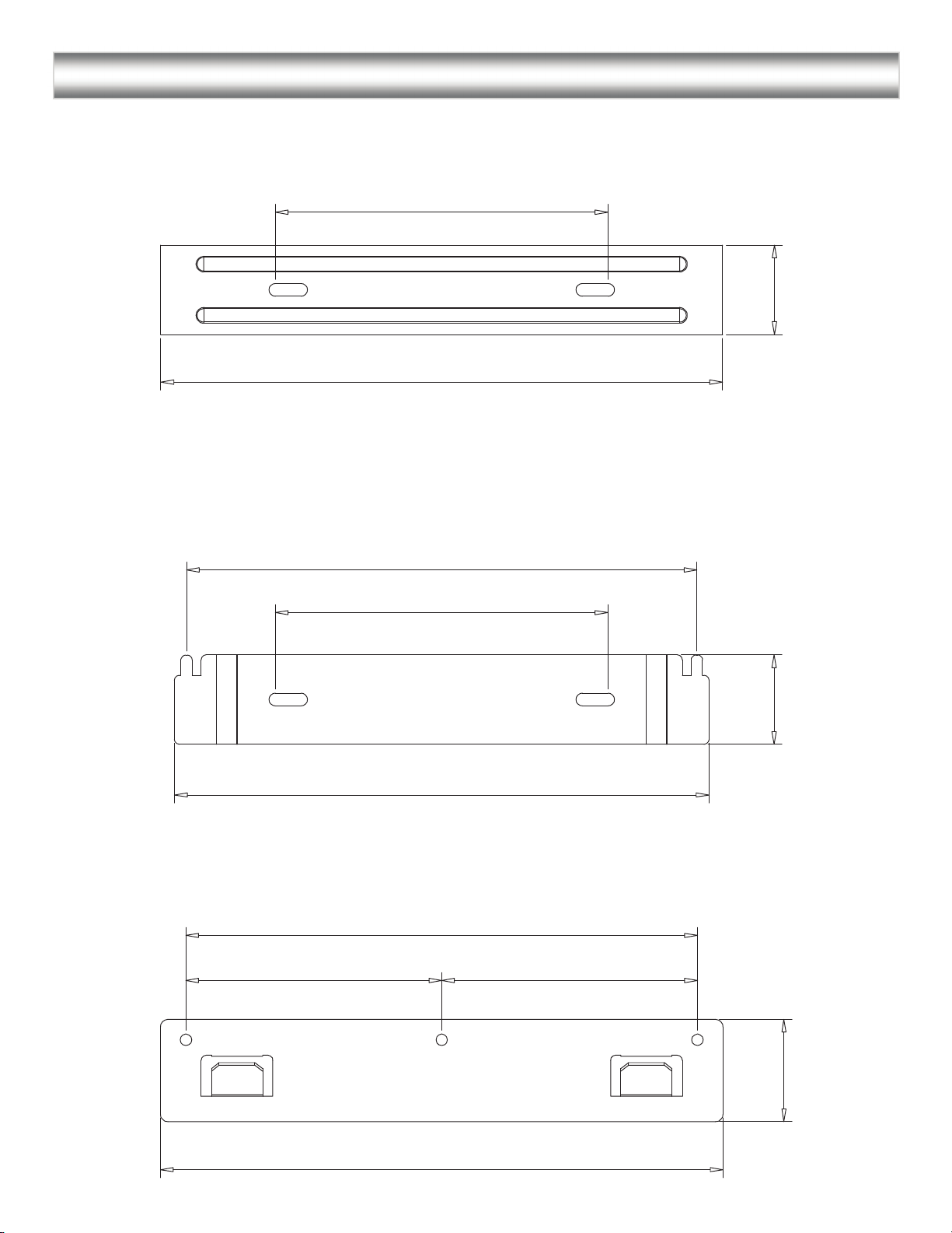
MOUNTING BRACKETS:
14
Upper Chimney Bracket
5 1/8” (13 cm)
8 21/32 (22 cm)
Lower Chimney Bracket
1 3/8”
(3.5 cm)
Mounting Bracket Hook
3 15/16” (10 cm)
7 7/8” (20 cm)
5 1/8” (13 cm)
1 3/8”
(3.5 cm)
8 5/8” (21.9 cm)
7 7/8” (20 cm)
3 15/16” (10 cm)
1 9/16”
(4 cm)
8 21/32” (22 cm)
Page 15
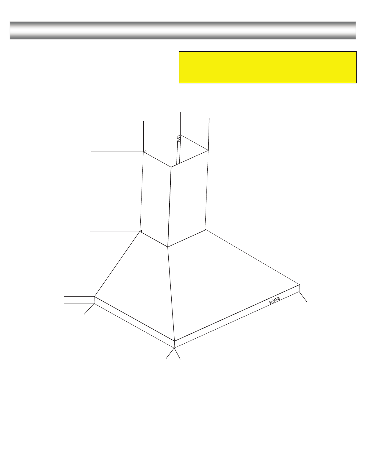
MEASUREMENTS AND DIAGRAMS:
15
Height of range hood: 26” - 41 3/8” (66 cm -105 cm)
The range hood can reach a 9’ ceiling if installed at 31”
from cooktop.
6.81’’
8.77’’
(223mm)
15.74” - 31.10’’
(400 - 790 mm)
(173mm)
8.85’’
(225 mm)
1.37’’
(35mm)
19.68’’
(500mm)
29.40’’
(747mm)
35 3/8’’
/
897mm)
Page 16
TROUBLE SHOOTING:
16
1)
If the range hood or LED light does not
operate after installation:
• Check if the range hood has been plugged in,
make sure that all power has been turned back
ON,fused not blown and all electrical wiring
are properly connected.
2) The range hood vibrates when the blower is on:
3) The blower or fan seems weak:
4) The lights work but the fan is not spinning at
all, is stuck or is rattling:
• The range hood might not have been secured
properly on to the ceiling or wall.
• Check that the duct sized used is at least 6” or
3-1/4 x 10”. Range hood WILL NOT function
efficiently with insufficient duct size. For
example: 7” duct over 6” hole and loosely
secured.
• Check if duct is clogged or if damper unit
(half-circular flange) is not installed correctly
or opening properly. A tight mesh on a side
wall cap unit might also cause restriction to the
air flow.
• The fan might be jammed or scraping the
bottom due to shipping damage. Please
contact us immediately.
• Make sure the distance between the stove top
and the bottom of the hood is within 24” and
30” in distance; with minimum 30” for gas
stove top.
5) The hood is not venting out properly:
• Reduce the number of elbows and length of
duct work. Check if all joints are properly
connected, sealed, and taped.
Page 17
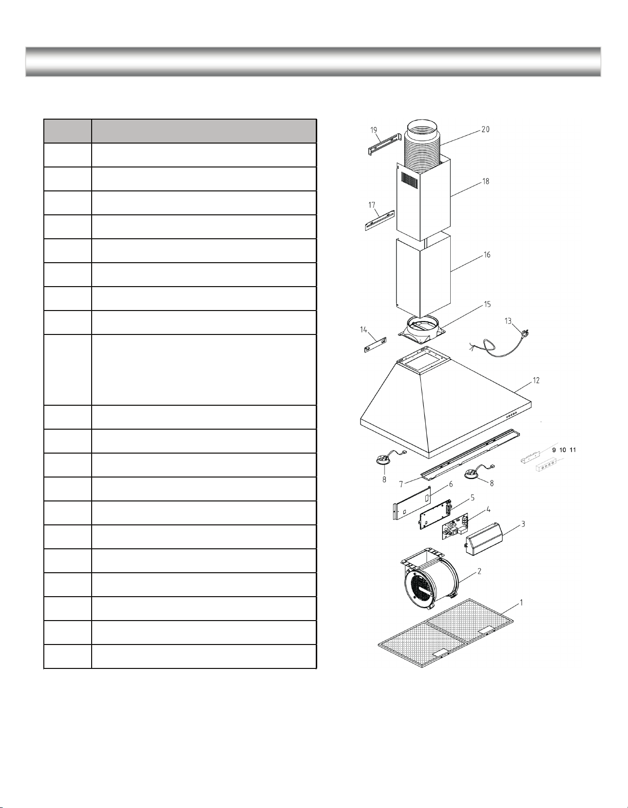
RANGE HOOD ASSEMBLY:
17
No. Description
20
19
18
17
16
15
14
13
Air pipe
Bracket of inner chimney
Inner chimney
Bracket of outer chimney
Outer chimney
Plastic wind block
Hook plate
Power cord
Body assembly
12
11
10
(including shell,lamp plate,top
plate,wrap angle,bracket of lamp
plate)
Electronic switch box
Electronic switch
9
Bracket of electronic switch box
8
Round LED lamp
Front panel
7
6
Bracket of electrical box
5
Electrical box base
4
PCB of electronic switch
3
Electrical box cover
2
Blower assembly
1
Baffle filters
Page 18
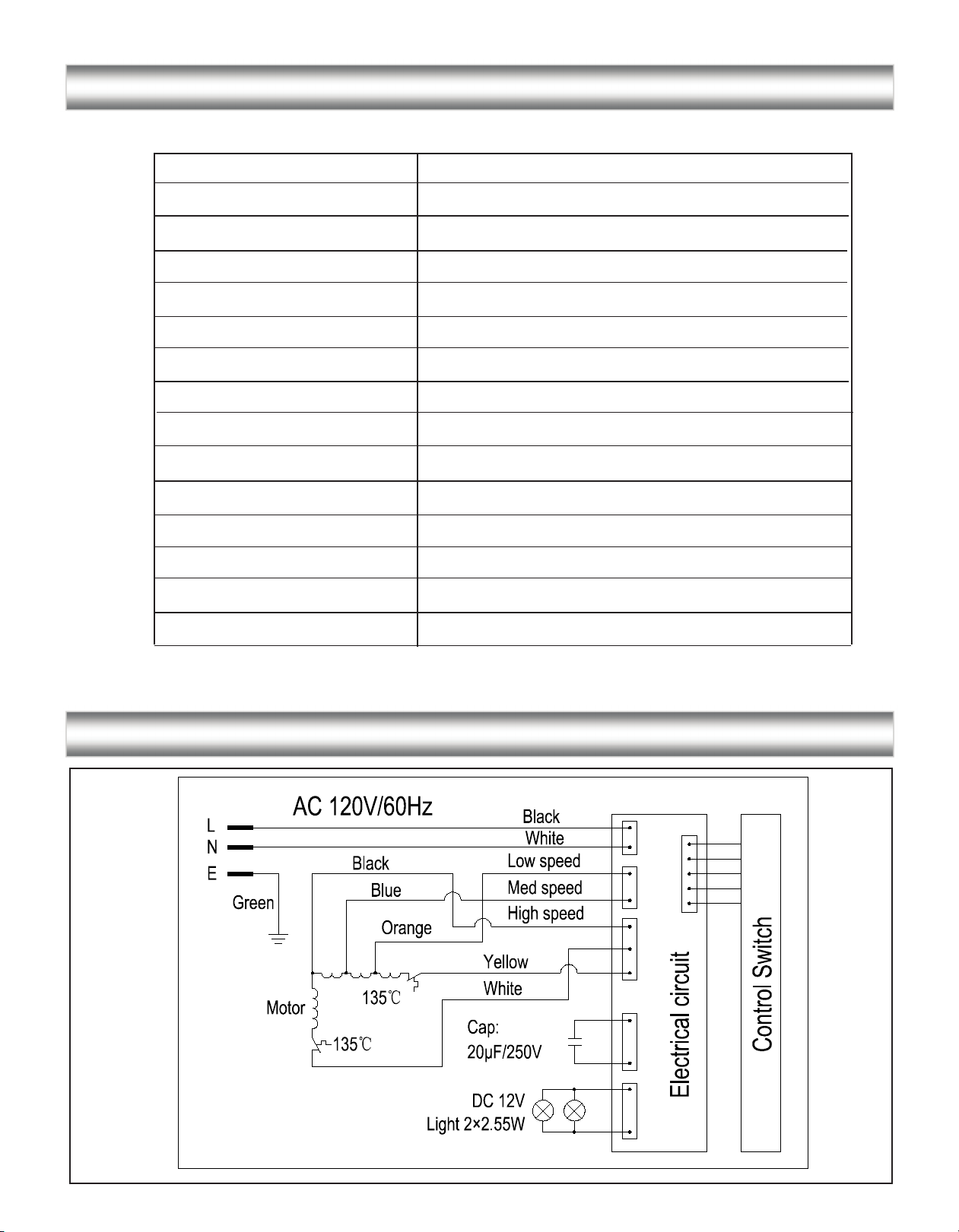
SPECIFICATIONS:
18
Body design
Power Rating
Total input power
Motor Input Power
Total Ampere
Levels of speed control
Interference Protection
Air Flow
Noise Level
Number of Motor
Fan Type
Control Type
Filtration Type
Illumination
Stainless steel
120V / 60Hz (USA & Canada standard) cETLus Certified
235.1W
230W
1.96A
3 levels
Radio frequency interference protected
400 CFM
Low speed 50 dBA
Single motor
Single chamber quiet
Electronic control
2 x Baffle filter
2 x 2.55W LED
Venting Size
Top, 6" Round
CIRCUIT DIAGRAM:
Page 19
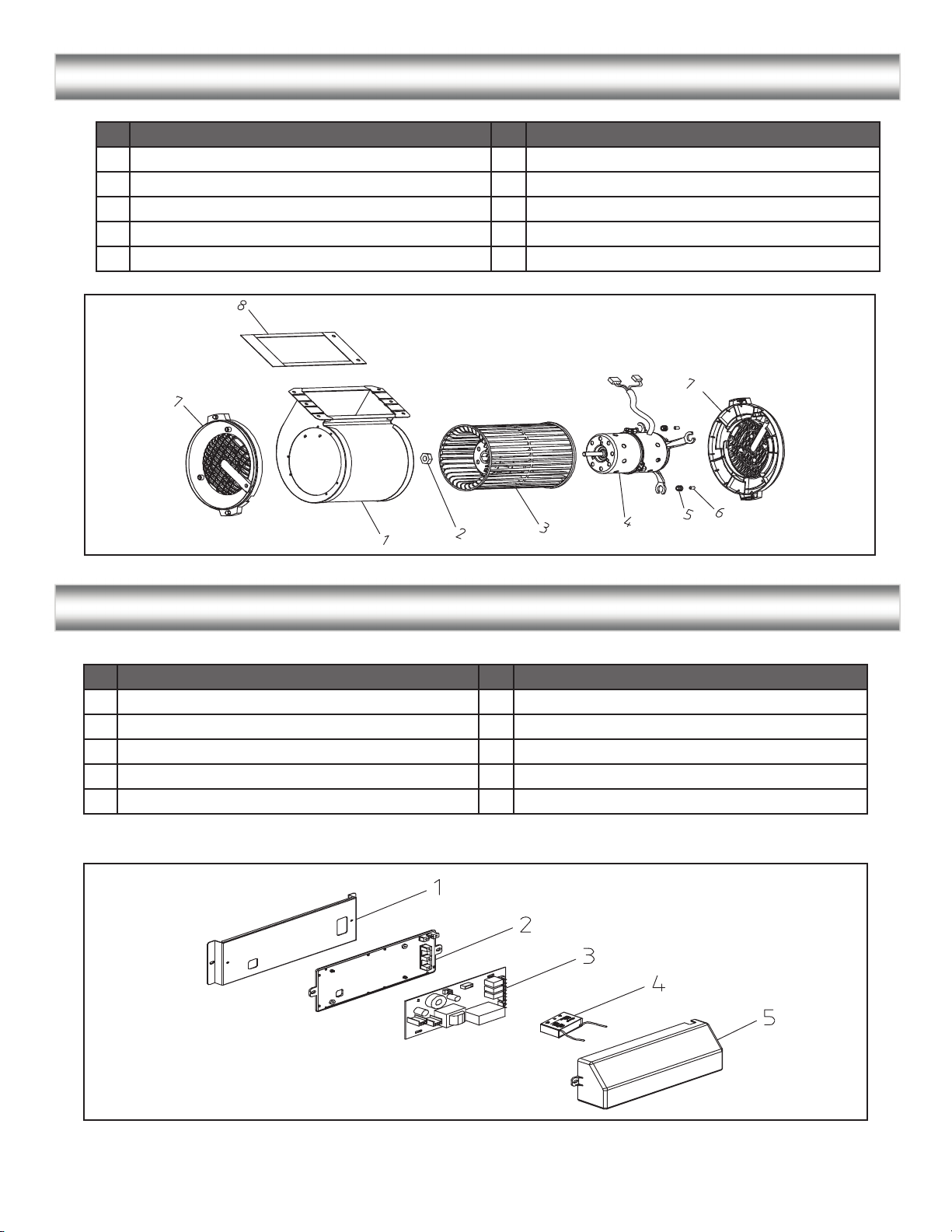
BLOWER ASSEMBLY:
19
No. No.Description Description
Blower
1
Wind Wheel Nut
2
3
Wind Wheel
Motor
4
Incabloc Rubber
5
Aluminum Cover
6
Plastic Wind Net
7
Sealing Gasket
8
ELECTRICAL ASSEMBLY:
No. No.Description Description
1
Electrical box bracket
2
Electrical box base
3
PCB
Capacitor
4
5
Electrical box cover
Page 20

USE AND CARE INFORMATION:
20
Operations:
• Read and understand all instructions and warnings in this manual before operating the appliance. Save these
instructions for future reference.
• Always leave safety grills and filters in place. Without these components, operating fans could catch on to
hair, fingers and loose clothing.
• NEVER dispose cigarette ashes, ignitable substances, or any foreign objects into fans.
• NEVER leave cooking unattended. When frying, oil in the pan can easily overheat and catch fire. The risk of
self combustion is higher when the oil has been used several times.
• NEVER cook on “open” flames under the range hood. Check deep-fryers during use; superheated oil may be
flammable.
Cleaning:
• The saturation of greasy residue in the fan and filters may cause increased inflammability. Keep unit clean
and free of grease and residue build-up at all times to prevent possible fires.
• Filters must be cleaned periodically and free from accumulation of cooking residue (see Cleaning
Instructions below). Old and worn filters must be replaced immediately.
• DO NOT operate fans when filters are removed. Never disassemble parts to clean without proper
instructions. Disassembly is recommended to be performed by qualified personnel only. Read and
understand all instructions and warnings in this manual before proceeding.
SAFETY WARNING: Never put your hand into area housing the fan while the fan is operating!
For optimal operation, clean range hood and all baffle/spacer/filter/grease tray/oil container regularly. Regular care
will help preserve the appearance of the range hood.
Cleaning Exterior Surfaces:
• Clean periodically with hot soapy water and clean cotton cloth. DO NOT use corrosive or abrasive detergent
(e.g. Comet Power Scrub®, EZ-Off® oven cleaner), or steel wool/scoring pads, which will scratch and damage
the stainless steel surface. For heavier soil use liquid degrease such as “Formula 409®” or “Fantastic®” brand
cleaner.
• If hood looks splotchy (stainless steel hood), use a stainless steel cleaner to clean the surface of the hood. Avoid
getting cleaning solution onto or into the control panel. Follow directions of the stainless steel cleaner.
CAUTION: DO NOT leave on too long as this may cause damage to hood finish. Use soft towel to wipe
off the cleaning solution, gently rub off any stubborn spots. Use dry soft towel to dry the hood.
• After cleaning, you may use non abrasive stainless steel polish such as 3M® or ZEP®, to polish and buff out
the stainless luster and grain. Always scrub lightly, with clean cotton cloth, and with the grain.
• DO NOT allow deposits to accumulate or remain on the hood.
• DO NOT use ordinary steel wool or steel brushes. Small bits of steel may adhere to the surface and cause
rusting.
• DO NOT allow salt solutions, disinfectants, bleaches, or cleaning compounds to remain in contact with
stainless steel for extended periods. Many of these compounds contain chemicals, which may be harmful.
Rinse with water after exposure to these compounds and wipe dry with a clean cloth.
Cleaning Filters:
IMPORTANT: Drain oil from baffles, spacers, filters, oil tunnels, oil containers before oil and residue overflow!
• Remove all baffles, spacers, filters, grease tray, and oil containers and discard oil and residue.
• Wash with warm soapy water. NOTE: Stainless steel baffles, spacers and oil tunnel are top rack dishwasher
safe.
• Dry thoroughly before replacing and follow directions for installation in reverse.
• Filters should be cleaned after every 30 hours of use.
• Should filters wear out due to age and prolonged use, replace with a new filter.
LED Replacement:
•
In the event the LED lights require servicing, please contact us at 1-888-686-0778 or email us at
[email protected]
 Loading...