

Page 1
1
1.
General
Edition 2019-01-03
Firstly, congratulations on purchasing your new Anchormatic 500 anchor winch!
You are always welcome to contact us should you have questions or suggestions.
Please read the entire manual. Consider reading it again after some time in order to maintain your knowledge.
The manual consists of eight sections:
1. General
page 1
5. Electronics
page 10
2. Placement of windlass
page 3
6. Calibration/Programming
page 11
3. User instructions
page 4
7. Safety
page 12
4. Installation
page 7
8. Accessories
page 13
Delivery
The windlass is delivered in a box. Enclosed in the box:
Windlass, Delivery Note and Folder with Instruction manual.
Check that the description is complete and that all items have been delivered in accordance with the delivery
note. Any discrepancies should be sent to us within one week.
The windlass consists of the anchor winch, Electrical connection box, Control panel and rollers. The left
side is called A and the right side is called B. Sometimes it is referred to as gable A and gable B.
The windlass is operated from the Control panel.
Page 2

2
- The visible parts of the windlass are the framework, the drum and the line guide.
- The electric engine is inside the drum. The brake is placed outside gable A. The clutch is placed on gable A.
- The wheels are numbered from 1 to 8 in the order in which they are driven from the engine via clutch
and
shaG of the drum, from drum to the screw holding the line guide.
- Chains are used for power transmission to wheels 3 to 6, otherwise belts are used.
- The line guide controls the rope (the rode) on the drum.
- Operational signal and electric power are controlled from a separate electronic box.
- ”UP” refers to retrieving the anchor (i. e. pulling the anchor up) and ”DOWN” refers to deploying the
an
chor (i. e. letting the anchor down).
- The windlass’ brake is always activated when the electrical current to the windlass is turned off,
prevent
ing the drum from letting go.
- When retrieving the anchor, the brake is released mechanically and the rode is rolled on the drum.
- When releasing the drum (pushing the DOWN button) the motor runs backwards for a fraction of a second. The centrifugal force then releases the clutch and the drum can roll freely. The corresponding action
can be achieved manually by turning the manual clutch handle (a large red knob) clockwise one tenth of a
turn. The anchor line must be unloaded to allow rotation of the knob. If the rode cannot be unloaded,
turn
the clutch shaG with a 13 mm (approximately ½ inch) wrench (spanner).
Page 3
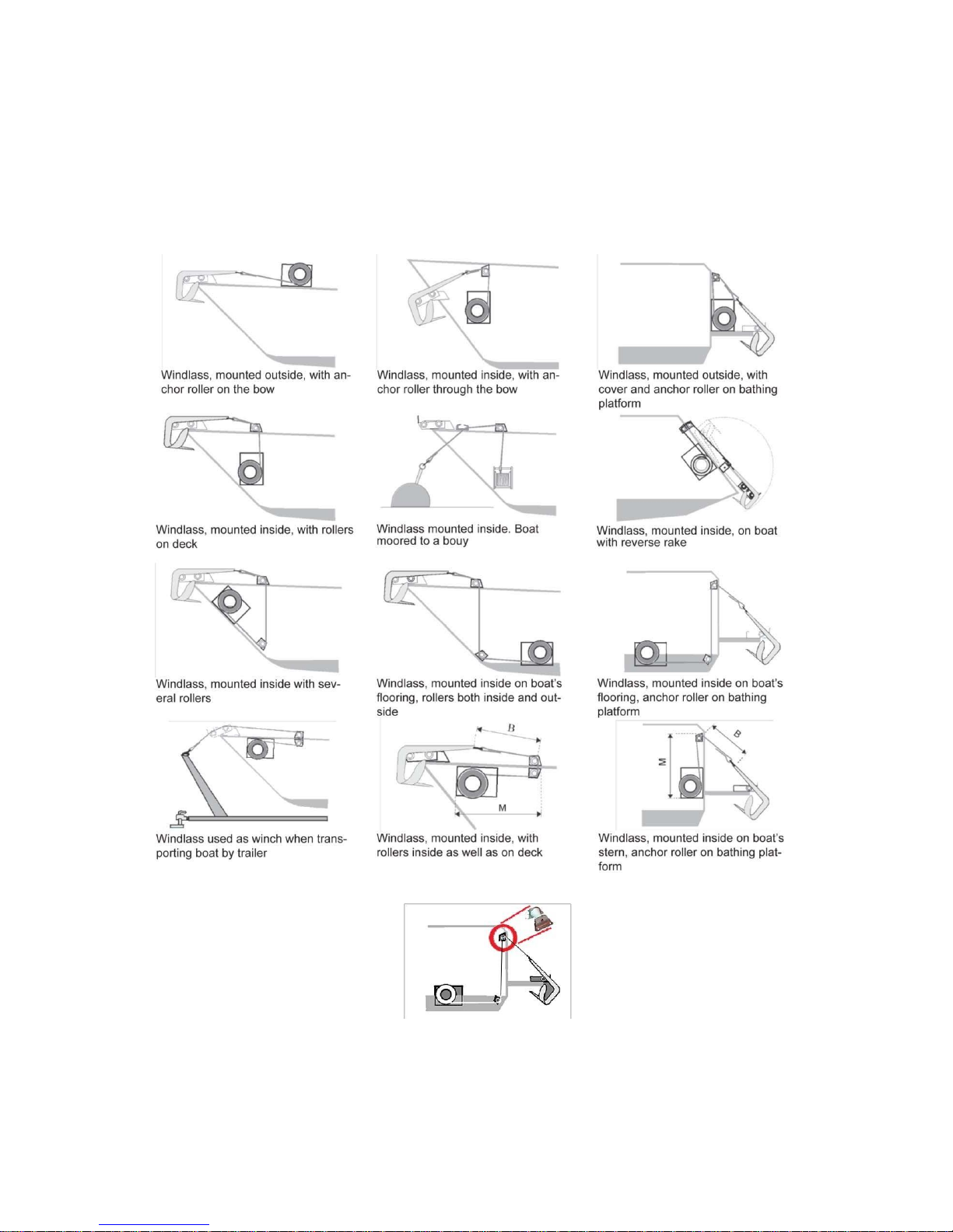
2. Suggestions on placement of windlass
The use of rollers:
3
Page 4
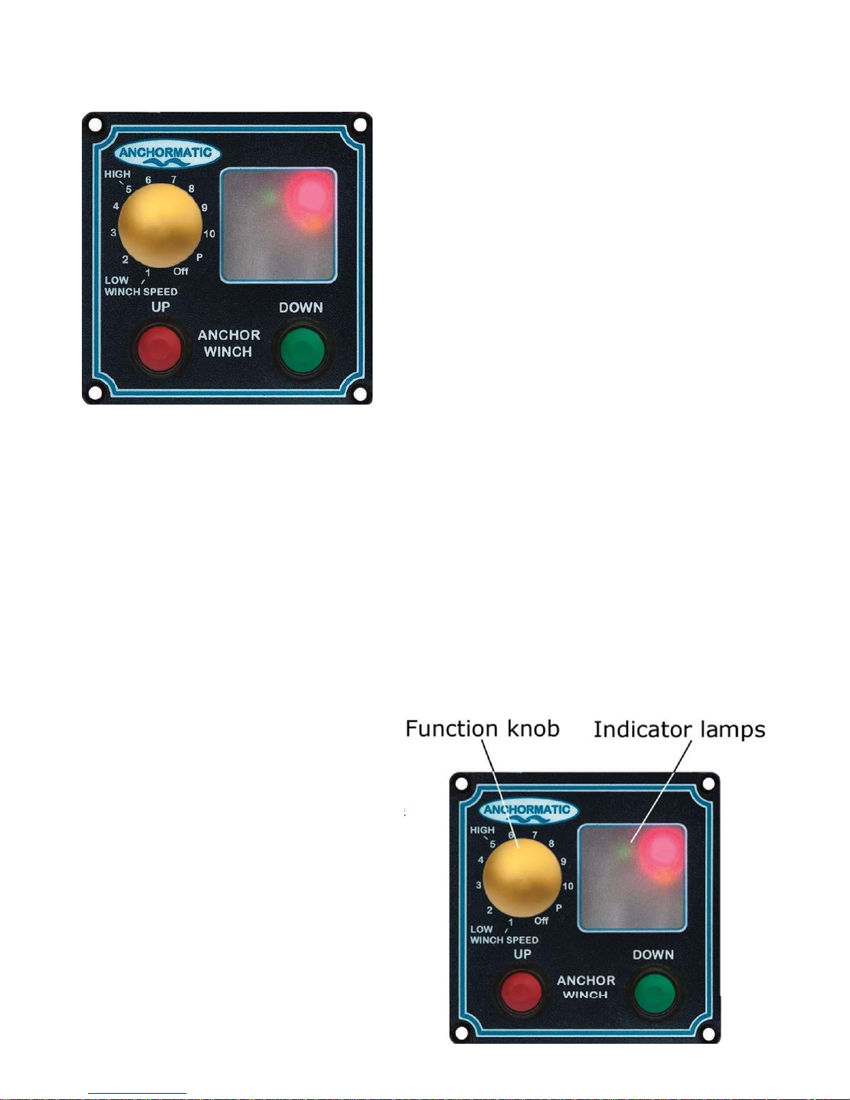
2. User instruction Normal pulling: 4
Control panel 710 1. The band drum is locked. Indicator lamps are off.
2. Turn function knob to either of positions 1-5.
1 = lowest and 5 = highest Pulling speed. Red indicator
lamp is lit.
3. Push the button “UP”. Red indicator lamp flashes
quickly.
4. When the anchor reaches rinse position, the green
and yellow indicator lamps are flashing continuously.
Release the button “UP”.
5. When the anchor is to be placed in its transport posi-
tion, push the button “UP”. Red indicator lamp flashes
slowly.
6. When the anchor has reached its transport position
the green indicator lamp is lit.
7. Turn the function knob to position “OFF”. The cur-
When the function knob is set to “Off” the currency is turned off, indicator lamps are off and the
windlass is locked.
Normal anchoring:
1. Indicator lamps are off. The anchor is in transport position. The windlass is locked.
2. Turn function knob to either of positions 1-5.
Green indicator lamp is lit continuously.
3. Push the button “DOWN”. The anchor runs out.
Red indicator lamp flashes quickly.
IMPORTANT! When the button “DOWN” is
pushed and the rode (band) is released and runs
out one should not push the button “UP” before
the anchor has reached the bottom. The clutch
might be damaged by the force of the outgoing
anchor.
4. When the anchor has reached the sea bottom, the
red indicator lamp is lit. Push the button “UP”. The
windlass is now locked.
5. Turn function knob to position “OFF”. The
currency is now turned off and the band drum is
locked.
IMPORTANT! It is obligatory to push the but-
ton “UP” before you turn the function knob to
position “OFF”.
rency is now turned off and the band drum is locked.
Practical tip! When the anchor is pulled, you ought to
start the pulling with the function knob in position “1”.
Move the function knob to a higher value, “2”, “3” up
to “5” the further out the boat moves. When the rode is
pointing straight down, release the button “UP” and let
the boat move to try to free the anchor from the bottom.
Push the button “UP” till the anchor stops in rinsing position.
Page 5

User instruction
It is simple to use our windlass. After having used it a few times you will master the technique.
The most frequent problem is too low a voltage. Check the battery before testing the windlass.
When turning on the windlass it is ready to use.
Electric current
Anchormatic Windlass ep-500 is equipped with a permanent magnet electrical engine. In order to get the
correct voltage it is very important to have fully charged battery and charging the battery running the
engine’s charger. Short time usage can be carried out using the battery only.
Anchoring and releasing
The windlass is released by pushing the DOWN button. The windlass engine will start to help releasing the
anchor which will drop from its own weight.
IMPORTANT! When DOWN is pushed and the rode (band) is released and runs out, do not push UP before
the anchor has reached the bottom. The clutch might be damaged by the force of the outgoing anchor. When
the anchor has reached the bottom and you have positioned the boat where you want it push UP. Always end
each operation by pushing UP. This will lock the windlass so rode (band) cannot run out. NEVER leave the
boat without having pushed UP. The windlass drum
Pulling
The pulling of the anchor goes on as long as the UP button is pushed. See to it the anchor band is stretched
during pulling. Always keep an eye on the anchor during the last part of the pulling. You may let the boat
drift by the wind and pull in against the wind. NEVER go in reverse while pulling in the anchor! You may
reduce the boat’s acceleration by pushing the up button in intervals. The auto stop function stops the pulling
of the anchor when it has reached the wash off (rinse position. By having the anchor in this position you may
wash off sand, clay etc from the anchor. By pushing the UP button on the Control panel the anchor is pulled
with lower tension and slow speed to its final position. Then turn then off the windlass.
Control panel 711 (optional)
With this control panel the position of the anchor (transport, rinse, falling or being pulled), the length of the
anchor band (rode) and the actual force of the windlass engine can be monitored.
Wireless control (optional)
Aim the wireless control unit towards the receiver’s antenna. The active distance is about 30 m (100 feet).
Finish off by pushing the UP button to lock the windlass.
What might be the cause…?
If the windlass refuses to release, please check the battery.
IMPORTANT! The function knob must be in position“OFF”during voyage to lock the anchor in its trans-
port position.
Let the boat’s generator charge the battery while pulling the anchor. Watch the anchor band during the
pulling.
If wind speed is high, place the anchor band around a boat pollar.
5
Page 6

6
4. Installation
The windlass
Think through the installation before you start the mounting. A recommended procedure is to place
the windlass and rollers as you have designed the installation and wait until the next day before you
start the actual job. Sometimes a better idea might present itself. Use screw clamps to do a
preliminary mounting. Check the angles of the anchor band and check that the band goes correctly
through
the rollers. ThereaGer it is best to start making the hole in the hull and fasten the hull
protector.
The windlass can be placed wherever you find it suitable, even upside down, as long as the drum
shaG is placed horizontally. It should be placed in a space that cannot be filled by sea water.
The windlass might be placed on a support if the bottom forms a slope and the drum shaG can’t be
placed horizontally.
Please note
! Some water might be transported into the boat by the wet anchor band. Use some sort
of protection so the water does not drip into a stow area (e. g. a tube of some sort).
You may lead the rode at any angle as long as it doesn’t get tangled or, under thigh tension, runs off
pulleys or rollers.
Please observe the dimensions of “B” and “M”.
Dimension “M”
is the distance between the windlass and the nearest roller or pulley and it is
depen
dent on the displacement of the boat.
Boat’s
displacement
metric tons
M - mm M - inches
3
600
24
5
650
26
8
750
30
11
850
33
It should be as long as possible to minimize the tension on the line guide.
Dimension “B”
is the distance between the anchor and the first roller or pulley. Observing this
distance gives the shackle and the end loop of the rode space so they don’t get in touch with the
first
roller. It should be at least 150 mm (6 inches) and preferably 250 mm (10 inches).
Use strong mounting points. Always use M 8 (1/3 inch) bolts and large nuts and washers taking up
the high tension. The largest tension will come upon the roller or pulley. Use only stainless steel of the
highest quality. Put a drop of oil on the thread so it doesn’t get stuck. Use a sealant e. g. Sikaflex®
Page 7
7
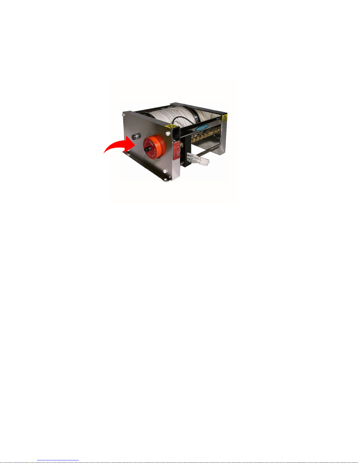
The windlass should be placed so the manual clutch handle is easily accessible. Please see Image 1.
Image 1
The electric connection box
The electronic box shall be positioned in a dry, ventilated space and oriented so water can’t follow
the cables into that space.
The electric connection box should be connected to the starter battery in order to get the highest
possible voltage when retrieving in the anchor. The processor needs to have enough voltage at all
times. If the distance from the battery to the electronic box is too far, a supplementary battery may
need to be placed closer to the box. (For suggestions on cable areas, please see image 8 below).
When installing cables, all instructions in this document need to be precisely followed.
The automatic fuse shall be placed on the plus (+) cable and so it is easily accessible. The automatic
fuse works as a safety guard for the electric motor and will be released should the tension on the
anchor be too high.
The optional safety switch for the windlass should be placed conveniently near the boat’s other
controls e. g. in the cockpit to give complete control over the anchoring procedure. Several Control
panels may be coupled to each other (parallel), both Control panel 710 and 711.
The wireless receiver should be placed as free from obstructions as possible and not too close to
metal objects so as not to interfere with the signal sent from the wireless control unit. The control
unit is only used for short periods of time to make adjustments. Its battery is rather small.
Page 8
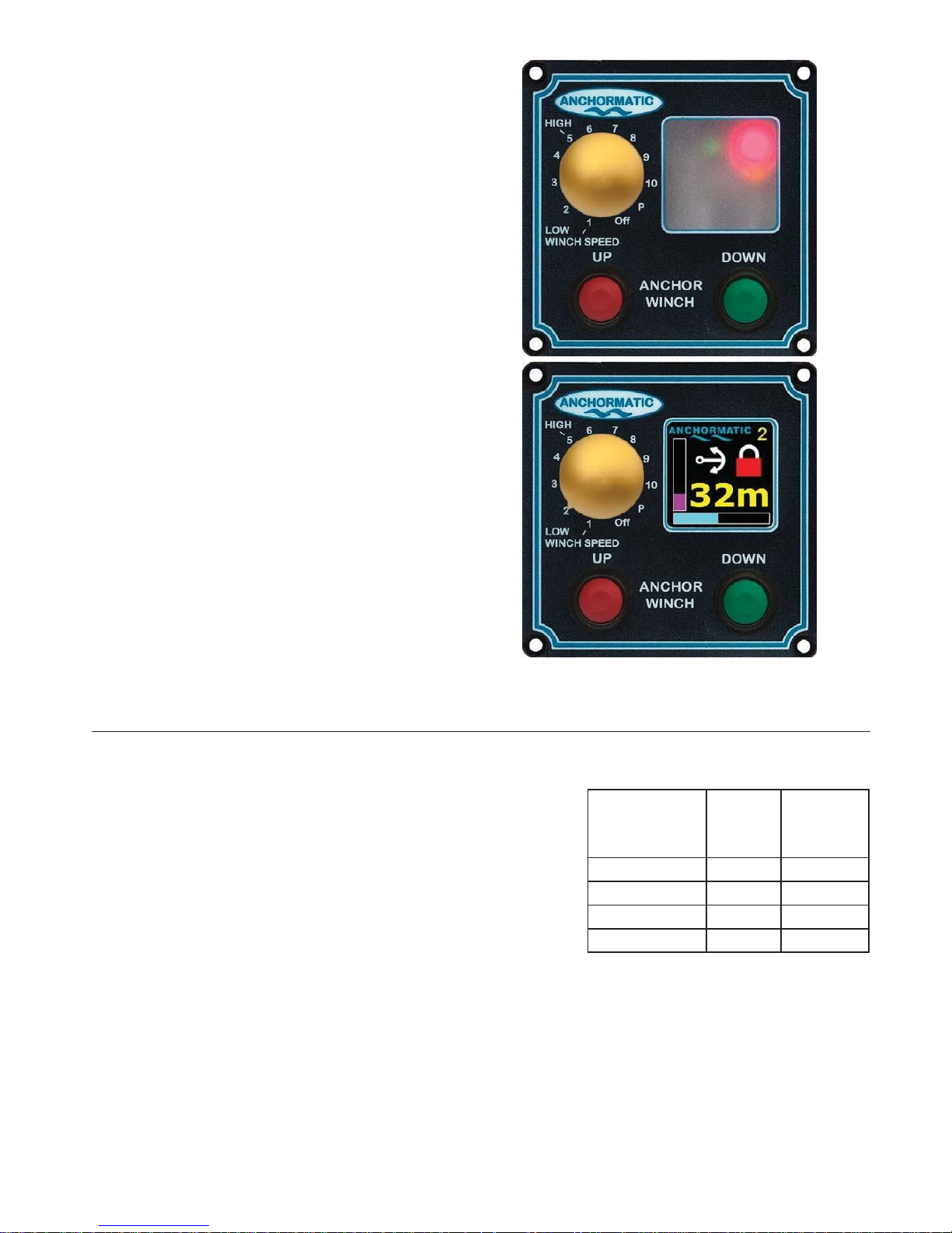
Control Panel 710,
included in the windlass package, should
be protected from rain, splashes and strong UV radiation. It
is water resistant providing a sealant is used during
mounting.
The cable from the Control panel should be attached to the
electrical connection box’s plinth, color-to-color. Please see
pages 10, 10a and 10b.
Control Panel 711
, an accessory,
should likewise be
protected from rain, splashes and strong UV radiation. It is
water
resistant providing a sealant is used during
mounting.
A hinged, transparent plate are recommended. Though, mounting
the Control Panel in a dry place is the best alternative.
Control Panel 711
has a window showing the position of
the anchor. the length of rode out is shown both
graphi
cally (the light blue graph) as well as numerically
(“32m”), in meters. The relative power used to pull in
the anchor is shown in the vertical, violet graph. The
speed of the rode
when pulled in is shown numerically
(“2”). If the wind-
lass is locked, a closed lock is shown.
If the windlass isn’t locked, an open lock is shown. If the
anchor is in its trans- port position, the lock is colored
green. If the anchor is in
the water, the lock is red.
Installation Summary:
1. Place the axle of the winch drum horizontally.
2. Align the roller(s) and the anchor roller in line with the center of
the
winch’s drum.
3. Please observe the measurements for ”B” and ”M”.
“B” should be at
least 150mm (6 inches) and preferably 250 mm (10 inches).
4. Use a strong mounting place.
5. Place the electronic box so it is protected from water.
6. Calibrate and encode before testing.
Please see next page for an overview of electrical installation.
8
Boat’s
displacement
metric tons
M - mm
M - inches
3 600 24 5 650 26 8 750 30 11 850 33
Page 9
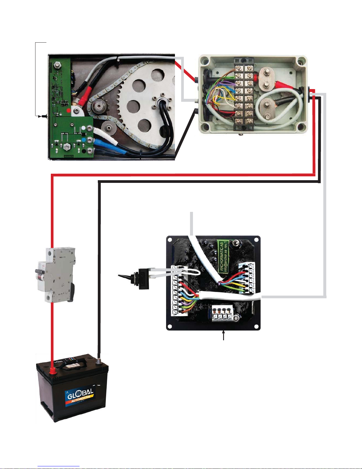
5. Electronics
Emergency switch. See page 2-3.
Windlass with circuit card
Electrical connection box
The cable from the control panel
is connected color-to-color
To radio receiver
10 m cable
to be
connected
to
connection
box
Autoswitch -
Safety switch optional
circuit breaker
Controllerpanel
back side
+ -
Connection of slave Control Panel
12 V alt. 24 V
starter battery.
Battery cable length :
0-2 meter ( 0-6 feet) 16 mm
2
2-4 meter ( 6-13 feet) 25 mm
2
4-5 meter (13-16 feet) 35 mm
2
5-8 meter (16-26 feet) 50 mm
2
8-10 meter (26-33 feet) 70 mm
2
Consider an extra battery if the cabel is too long.
9
Page 10
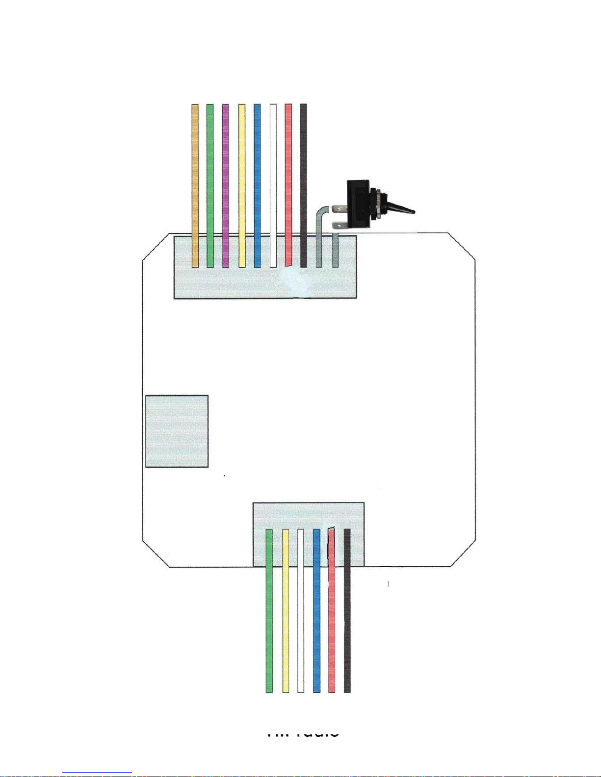
10
To radio receiver
To Electrical connection box
Page 11
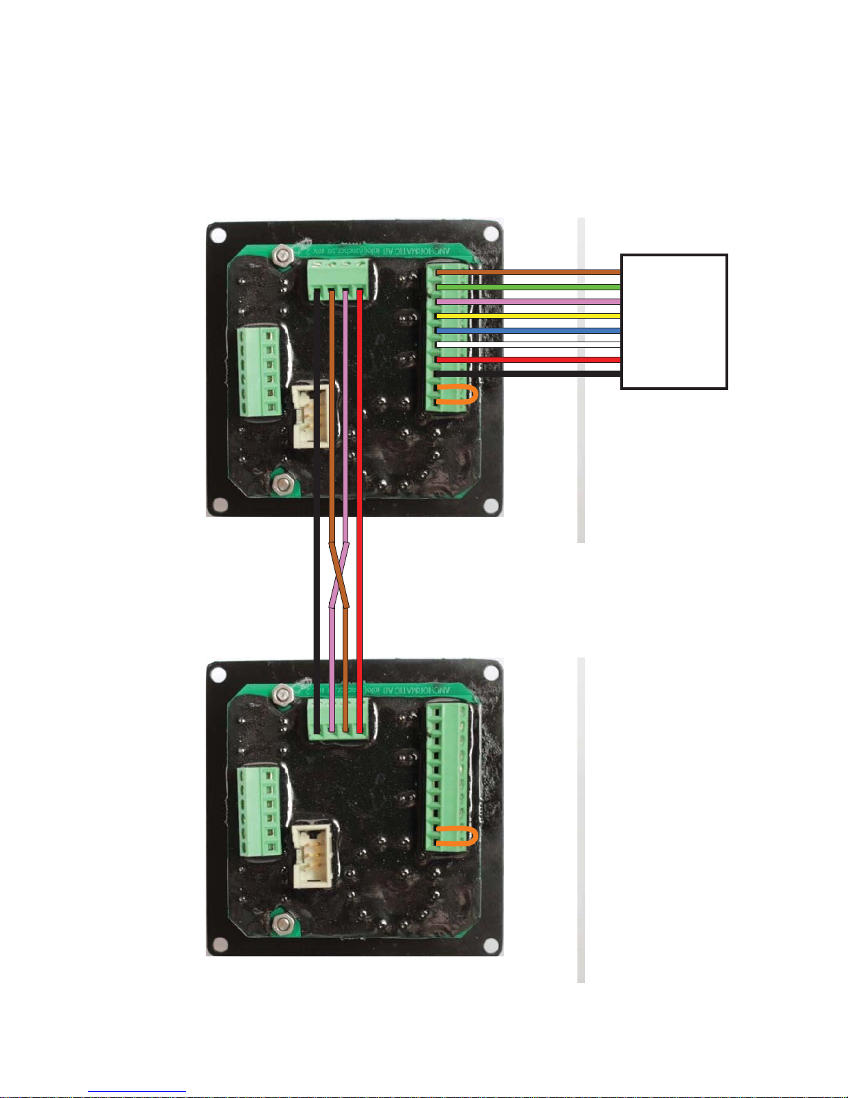
Master and slave connection of
Control Panels
10a
Master
Slave
Connection
box
Note!
Brown and violet cables
MUST be cross connected!
Page 12

6. Calibrating/Programming rinse and stop positions for anchor
11
The programming will be carried out with the anchor in the water. The black patch on the rode
MUST be outside the windlass. The easiest way to carry out the calibration is to let the anchor
out and let it reach the bottom. The depth ought to be more than five meters.
1. Push the ”DOWN” button once. The anchor will be dropped.
IMPORTANT! When the button “DOWN” is pushed and the rope (rode) is released and the an-
chord runs out, do not push the “UP” button before the anchor has reached the bottom. The
clutch might be damaged by the force of the outgoing anchor.
2. See to it that the black patch on the rode has gone out of the windlass.
3. Lock the windlass by pushing the ”UP” button.
4. Push the ”UP” button till the anchor is in the rinsing position.
5. Turn the function knob to position ”P”.
6. Push at the same time both the ”UP” and the ”DOWN” buttons . Green lamp will fl ash twice.
For windlass WITH an anchor davit:
For windlass WITHOUT an anchor davit:
7. Release the ”UP” and ”DOWN” buttons and
turn the function knob to position ”1”.
8. Push the ”UP” button till the anchor is
placed in a position for transportation.
9. Turn the function knob to position ”P”.
10. Push at the same time both the ”UP” and
the ”DOWN” buttons . Green lamp will fl ash
three times.
11. Turn the function knob to position ”OFF”
The positions for rinse and stop are now
programmed for windlass WITH anchor
davit.
7. Release the ”UP” and ”DOWN” buttons.
8. Push the buttons “UP” and “DOWN” at the
same time once. Green lamp will fl ash three
(3) times.
9. Turn the function knob to position ”OFF”.
The positions for rinse and stop are now
programmed for windlass WITHOUT anchor
davit.
If you want to change the programmed rinse and stop positions, turn the function knob to position
“P” and push the two buttons “UP” and “Down” at the same time. The red light will fl ash for two
seconds indicating the programmed positions have been erased.
Important! Both the rinse and stop positions must be programmed for a safe use of the windlass.
Page 13

6. Safety
12
PRECAUTIONARY MEASURES
Use strong fastening points for windlass and rollers. Preferably place windlass and rollers so they are not tripped over.
Cover windlass and rollers with covers to avoid injuries. If at risk, also cover the anchor rode.
Place electrical and electronic equipment in a dry place so water or moisture cannot come in contact with the cables.
Control panels should be placed so the anchoring can be done in a controlled manner. The best placement is to have
one Control panel at the helm and one at the stern. A Control panel placed at the stern is especially good as it
en
ables the operator to stand on the aG (poop) deck and retrieve the anchor in a controlled manner. Place the Control
panel so you can reach it should you need to take away debris stuck to the anchor.
The safety switch should be placed in the vicinity of the Control panel in order to act as an emergency stop.
The switch should be placed out of reach of children.
The electric connection box should be placed in a dry and ventilated space
Mounting, adjusting and maintenance.
The line guide goes from side to side with great force when the rode is moving in or out.
WARNING! Do not touch it
while moving! It is strong enough to break a finger. Never touch the windlass while it is operating under power!
Never perform any electrical or electronic work with the windlass turned on.
Regularly check all electrical connections. Also check that the windlass and the rollers are securely fastened.
Usage
The windlass should always be TURNED OFF during passage making. In the off position the windlass is locked and the
electronics are protected against hazardous electrical surges.
Keep the wireless control unit out of reach of children.
Keep children and inexperienced crew members away from the windlass and its moving parts.
Never touch a moving anchor rode.
See to it that no foreign objects ( e. g. loose ropes ) are near the windlass when in operation. Especially
dangerous
parts are the line guide and rollers.
See to it there is sufficient space to reach the button to manually disengage the drum on the windlass.
Page 14
7. Pulleys, anchor rollers and covers
13
Pulley
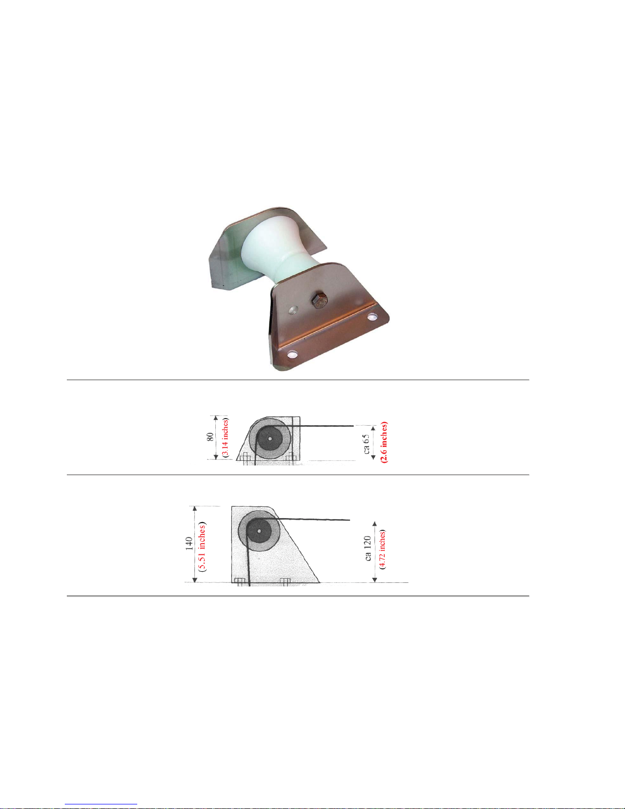
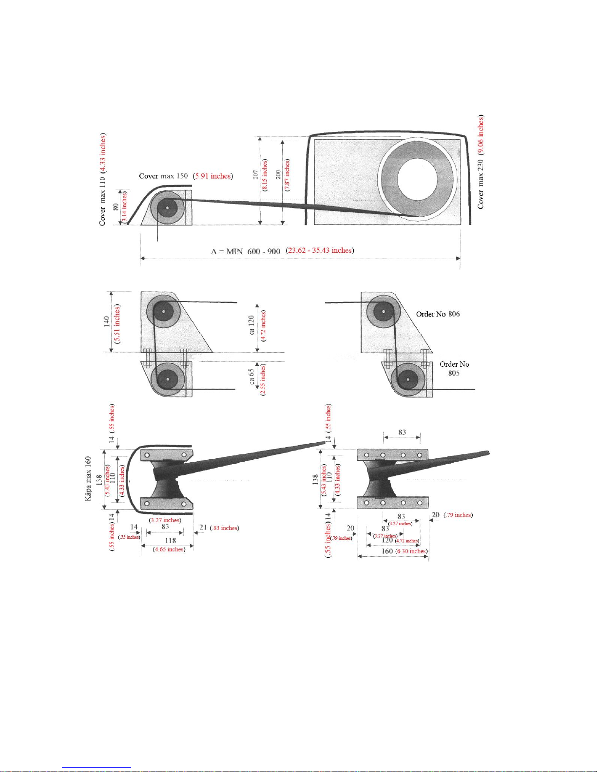
Pulley order No 805 and Pulley order No 806 is used to angle the rode.
Pulley order No 805
, distance rode – support: 65 mm.
Pulley order No 806
, distance rode – support: 120 mm.
Pulleys order No 805 and order No 806 can be used separately or combined. Screw hole diameter 9 mm, fits
bolt M8. Hole pattern 110 x 83 mm. Pulley cover order No 808 fits only Pulley order No 805. If Pulley order No
806 is combined with Winch cover order No 807, the opening of this cover needs to be enlarged.
Page 15
14
Single anchor roller
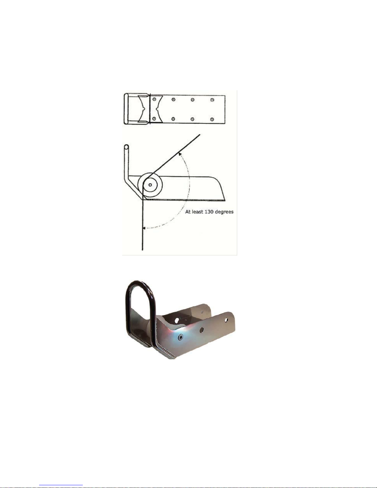
The single anchor roller is used mainly for bathing platforms, where the angle formed by the rope (rode) is
greater than 130 degrees. At an angle less than 130 degrees the articulated anchor roller is recommended.
Fasten the anchor roller with at least four screws. M (recommended). Anchor roller’s holes are 9 mm wide in
both directions. Aim for a as large distance as possible between the screws in order to reduce the burden in the
event of side spin
of the anchor rope (rode). Place the anchor roller as far out on the bathing platform as
possible to prevent the anchor from swinging and hitting the boat.
Page 16
15
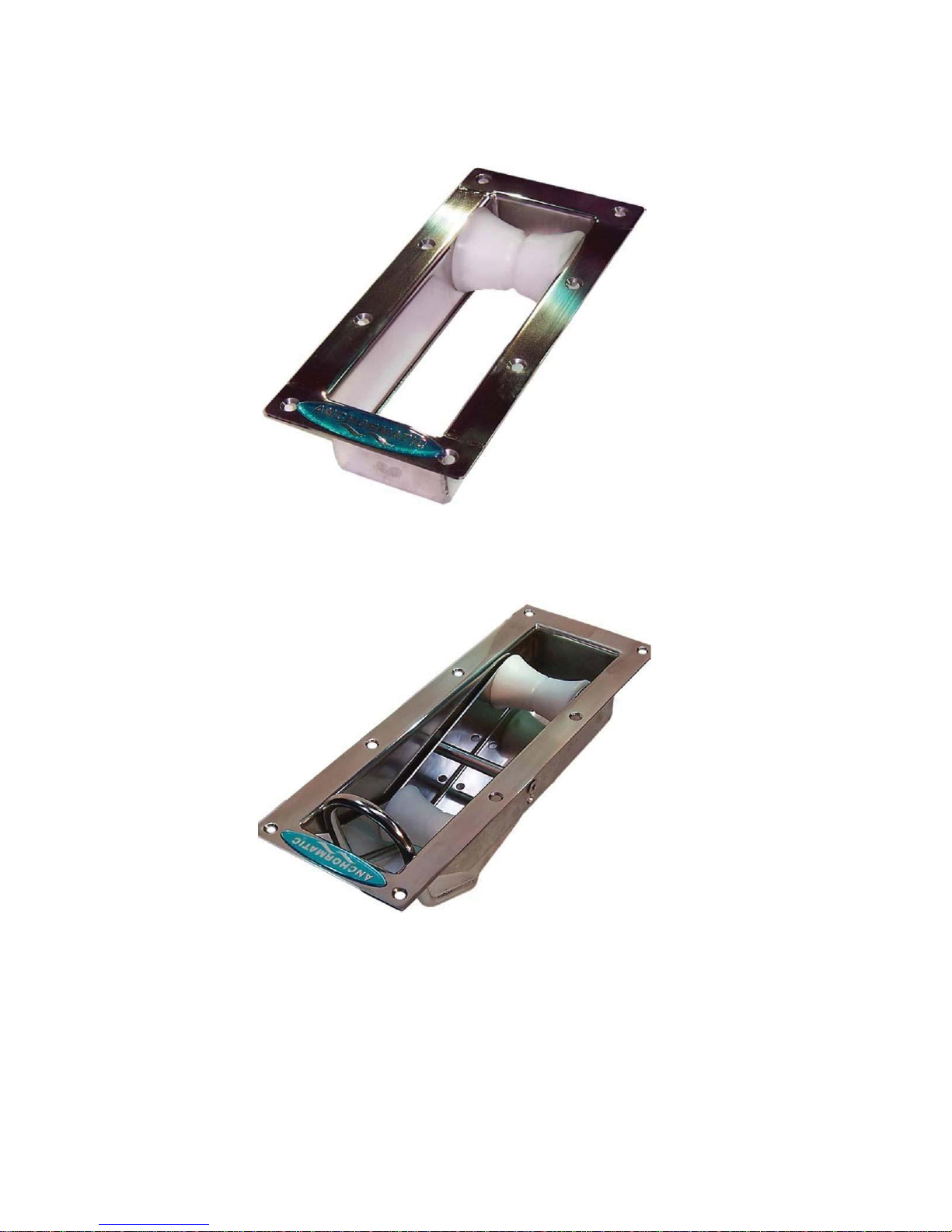
The inset anchor roller, order No. 802, is mostly used in conjunction with bathing platforms where the angle
formed by the rope (rode) is greater than 130 degrees. At an angle less than 130 degrees, the Inset articulated
anchor roller, order No 803, is recommended.
Both Inset anchor roller (order No 802) and Inset articulated
roller (order No 803) are fastened to the bathing platform with eight recessed M6 screws. The advantage of
these anchor rollers is that the anchor’s flukes will be placed below the bathing bridge. These anchor rollers
require
a longer bathing platform to avoid the anchor touching parts of the boat when deploying or retrieving in the
anchor.
Page 17
16
Inset anchor roller (order No 802)
Outer length x width: 300 x 140 mm (11.8 x 5.5 inches)
Outer length and width through bathing bridge 85 x 245 (3.3 x 9.6 inches)
Inset articulated roller (order No 803)
Outer length x width: 425 x 160 mm (16.7 x 6.3 inches)
Outer length and width through bathing bridge 100 x 370 mm (3.9 x 14.6 inches)
Articulated anchor rollers
Place the anchor roller so far outboard that the rode and the anchor itself are free from the stern
and/or the and bathing platform. Place the anchor roller as far outboard as possible on the bathing
bridge if the
anchor can swing towards the boat.
Page 18
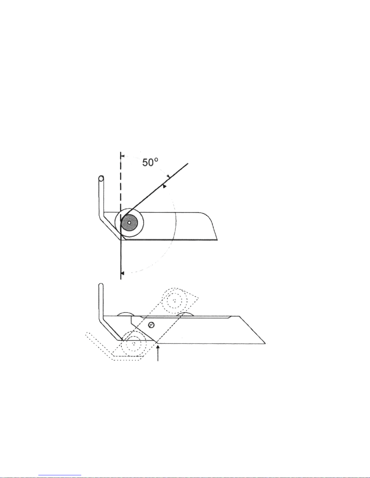
The outer end of the bottom plate should be placed at the outside edge of the bathing platform.
17
Fasten the anchor roller with four (4) 8 mm (.31 inch) screws. Anchor roller holes are 9mm (.35 inch) in
diameter. Aim for a large distance between the screws to increase the load surface and keep the anchor
roller in position also if the lengthwise angle of anchor rode is increased. Articulated anchor rollers are
available
in two lengths. Order No 804 is 100 mm (3.94 inches) longer than order No 801.
Place the anchor roller as far out as possible on the outer edge of the bathing bridge - n
ever inside.
Page 19
Davits
18
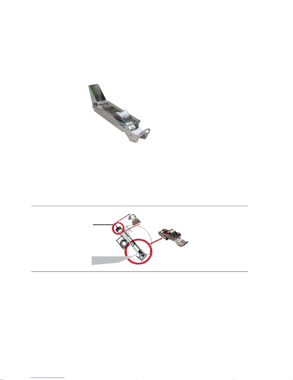
Davit, order No. 809 and order No. 810, is used on sailing boats with reverse rake, motor boats without
bathing platforms, motor sailors with or without bathing platforms and double enders.
Bottom length of order No 809 is 400 mm (15.75 inches) and order No 810 is 500 mm (19.69 inches).
Page 20
Covers
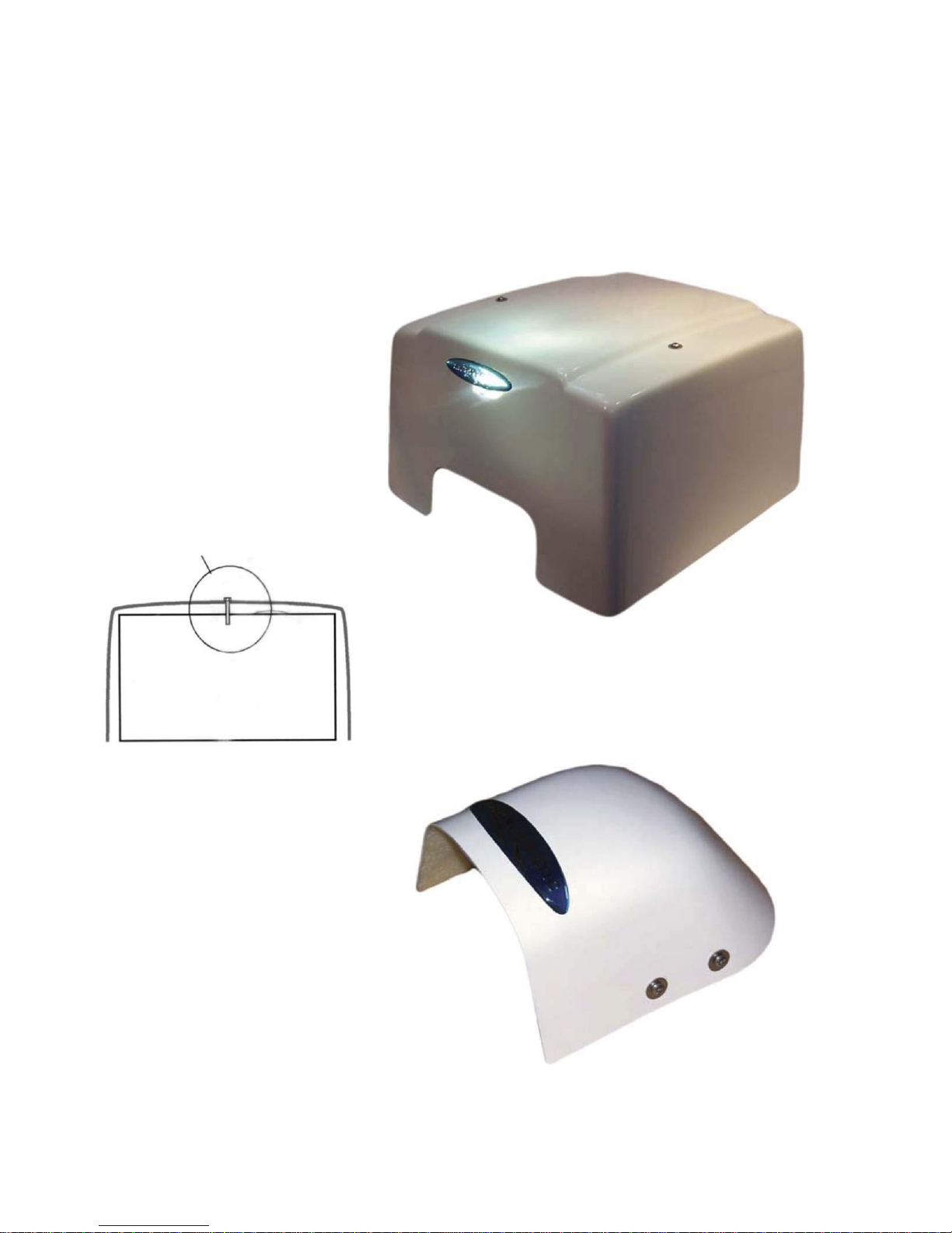
Winch cover
Cover’s maximum dimensions: 360 x
380 x 230 mm (14.17 x 14.96 x
9.05
inch). The cover shall normally be held
in place with two screws which press
the cover against the boat. Screw
holes in the winch’s gables are thread-
ed. Use a drop of oil on the screw to
ensure it goes in easily.
Pulley cover
Cover’s maximum dimensions:
190x170x130 mm (7.48 x 6.69 x
5.11
inch). Mount the angled steel bars on
top of the roller’s foot plates using
the roller’s screws. Screw the cover’s
fastening screws straight in towards
the angled steel bars. Use a drop of oil
on the fastening screws to make sure
they go into the screw holes easily.
19
Winch cover
Pulley cover
Page 21
Hull protector
20
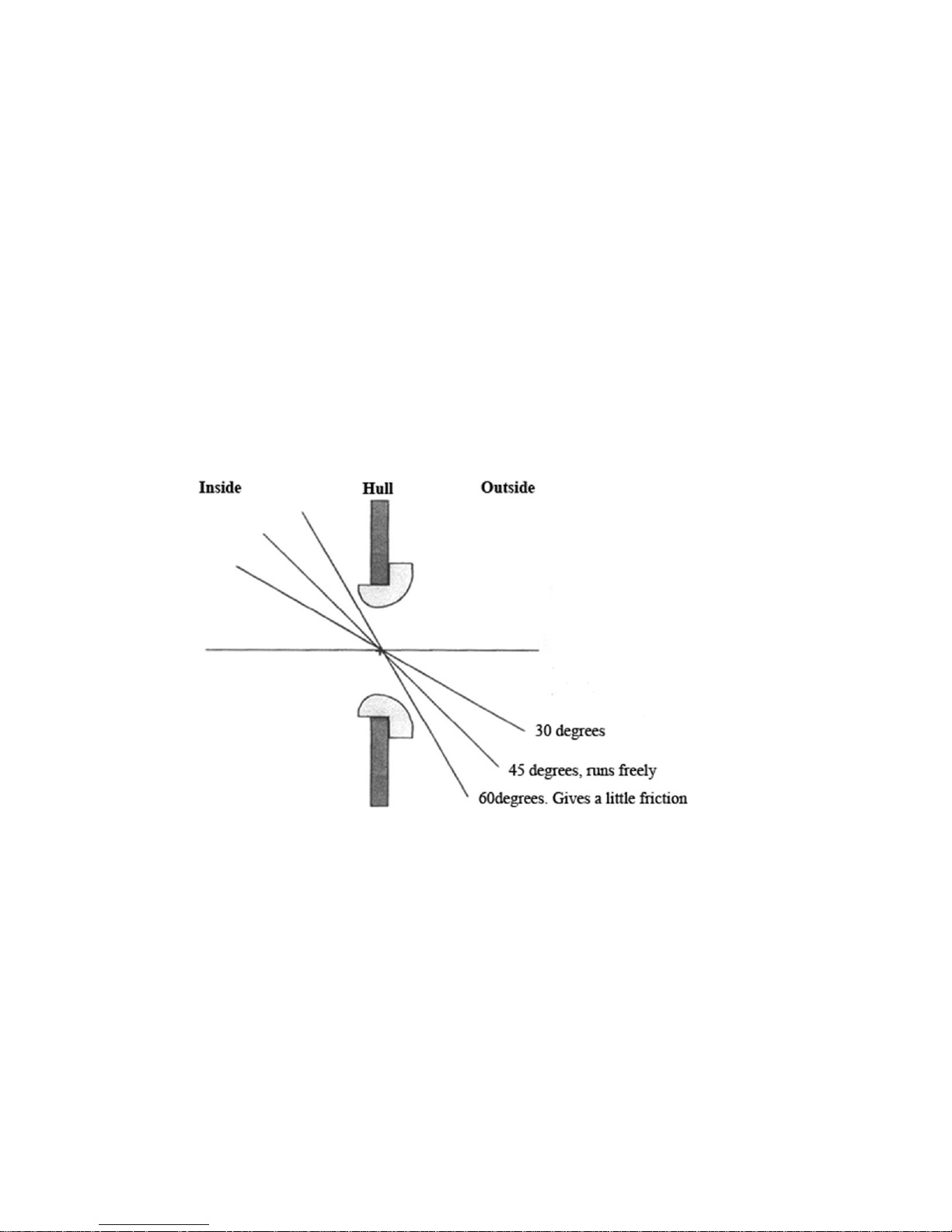
The protector, (protects the rode from edge damage) should be placed centrally to the rope’s (rode’s) path
to avoid friction and abrasion. Greater the angle = closer the fitting.
TIP:
Use a thin metal wire to find the
center of the rode’s path. “Horizontal Center” is located approx. 3 mm (.12 inch) inside the hull’s outer
surface. The hole should have a diameter of 57-58 mm (2.24 – 2.28 inch). Mount the hull protector on
the outside of the hull as the largest side forces are formed when hauling the rope (rode) in.
Glue the
hull protector to the hull using a sealant like Sikaflex® (http://www.sika.com) or similar.
Page 22
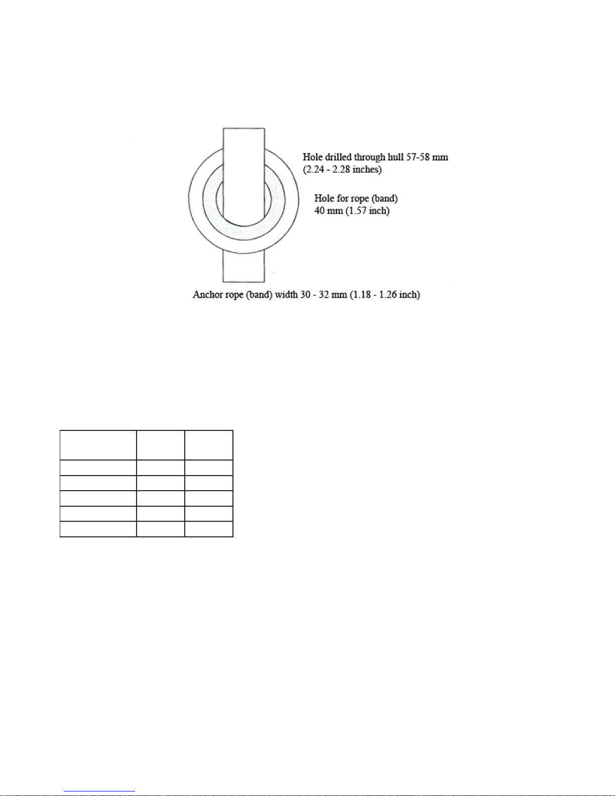
21
Measures (sizes)
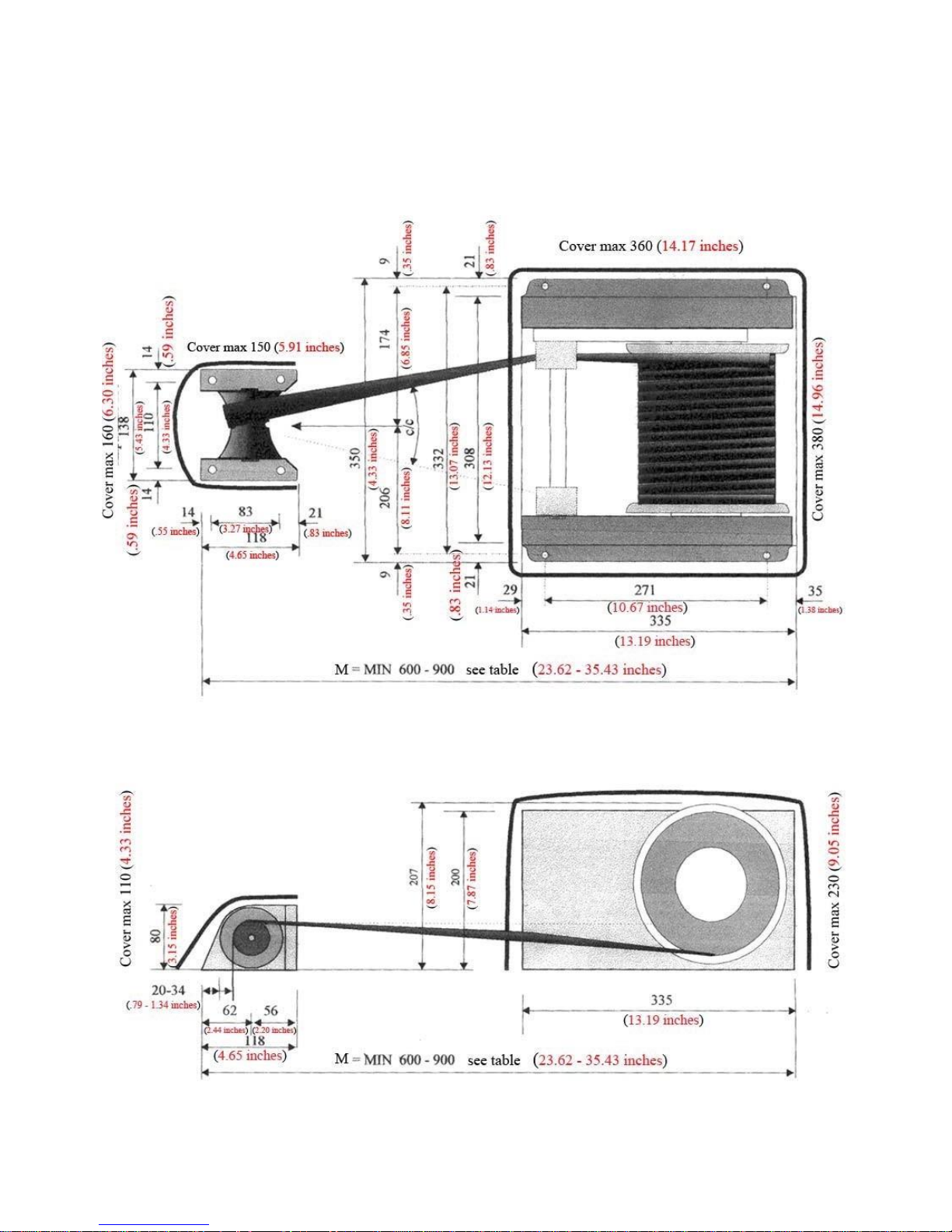
Holes diameter 9 mm (.35 inch) fits bolt M8 (.31 inch). Measure M should be as far as
pos-
sible to reduce strains on the line guide. Table of minimum dimensions (M)
Boat’s weight
metric tons
M, mm
M, inch
3 600 24 5 650 26 8 750 30 11 850 33 12 900 35.43
Please see next page.
Page 23
22
Page 24
8. Wireless control
23
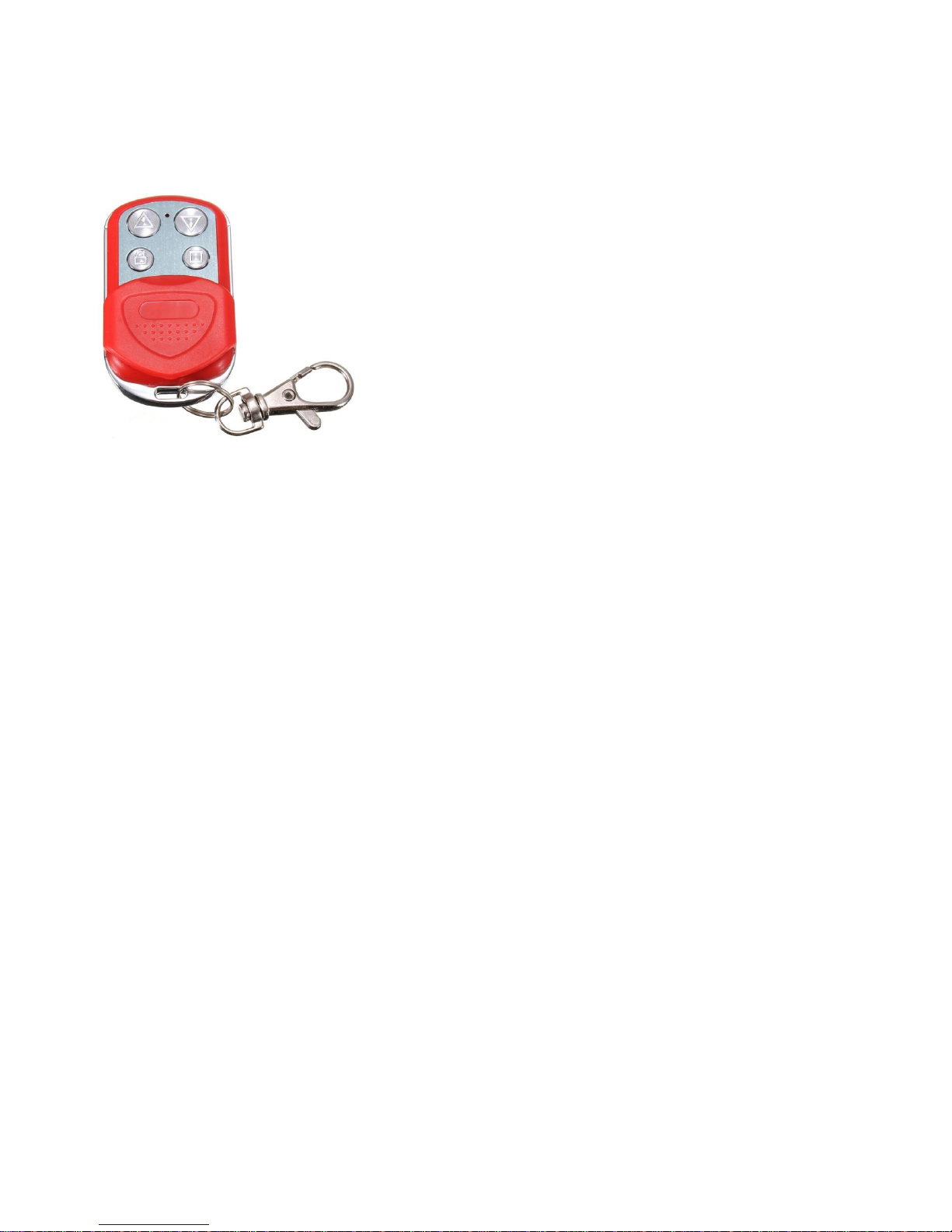
The wireless control consists of one handheld unit and a receiver. The typical reach with a properly
posi
tioned antenna and normal reception conditions is up to 100 G.
Protect the wireless control from moisture. Water, particularly salt water, is harmful to the electronic details. Transmitters and receivers are not watertight.
Antenna
Position the antenna as high and as unencumbered as possible. The antenna should stand straight up from
the receiver in order to obtain optimum reception. (The length of the antenna is adapted to the
appropriate wave length). Avoid any proximity to metal objects that could cause disruptive so-called
standing
waves.
If the reception is weak, the receiver with the antenna should be moved and, if necessary, the
connection cable must be replaced or extended. A spliced or lengthened antenna rarely provides
improved reception
results.
Receiver
The receiver box should be attached to a wall or similar. The receiver’s cable is connected to the Control
panel. Please see page 10 (“5 Electronics”) for connection details. Connect the colored wires as outlined on
the picture “Control panel back side” on page 10.
Operation
One push on the DOWN button releases the anchor
line.
One push on the UP button locks the anchor
line.
Continuously pushing the UP button retrieves the anchor line.
Changing the bat†ery
Type of battery: 27A12V. The battery in the wireless control ought to be changed every year. Unscrew the
three screws on the control unit’s back side. Open the unit carefully with a knife or a screwdriver. The
battery is placed in the outer part of the unit’s printed circuit board. The battery’s positive (+) side should
face the printed circuit board. Push the battery’s negative (-) end towards the little spring in the battery
holder
and let the battery snap into its position.
Page 25

Errors
24
If you experience problems with the control unit, first test to see if the windlass works with the control
panel. Weak or interrupted transmission
-Try to go closer to the antenna.
- If the antenna is obstructed, try avoiding the obstruction.
- If the battery is weak, change the battery.
In the case of damage, the wireless radio control should be returned to the supplier for repair or replacement. Anchormatic AB
Kustvägen 8 87031
Mjallom, Sweden
Tel: +46 8 88 50 50 e-mail: [email protected]
 Loading...