

Page 1
PZ-Series High Peak Appendix
PZHP 0912
Use this Appendix with the Anchor Structure PZ Manual
Assemble Arches as noted in the standard PZ manual except as follows for High Peak
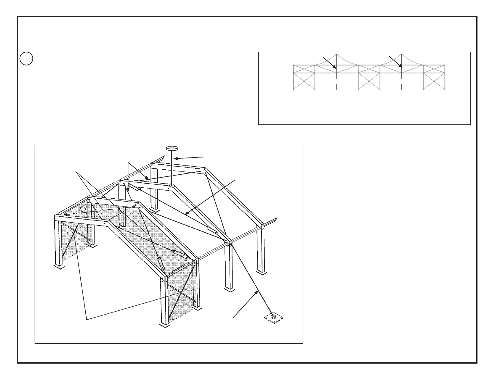
1
Arch: X-Cabling must be installed as shown in Figure 1a.
Figure 1b shows cabling in greater detail, the cross cable required on the High Peak
Arch, the cable guys required on the High Peak Arch and the High Peak attachment.
High Peak Bay
Roof Cables
Roof Cables
High Peak
Attachment
Standard X-Cabling must be installed in bays adjacent to to each set
of High Peak Bays.
Both Bays of the High Peak must have the modified X-Cabling as
shown above. Install as per Standard PZ instructions.
Cross cable
High Peak Arch
High Peak Arch
High Peak Bays
High Peak Bays
Figure 1a
EC 4582
Upright Cables
Cable Guy
Figure 1b
PZHP 0912
Page 2
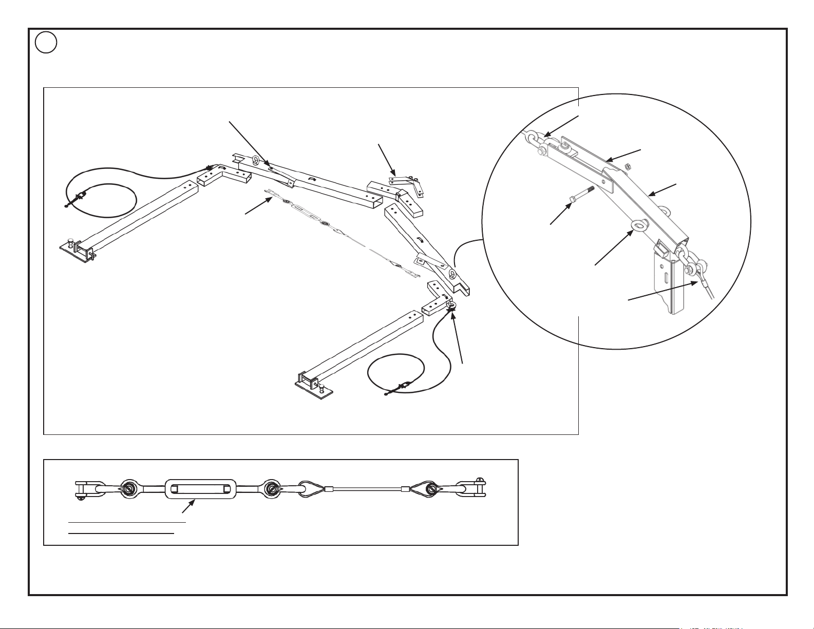
Assemble High Peak Arch as shown in Figure 2a while still lying on the ground.
2
Cross Cable Attachment Plate.
Cross Cable.
High Peak Arch
High Peak Mounting Plate. Install
using 10mm x 80mm bolt and nut.
Guy Cable
Cross Cable
Cross Cable
Attachment Plate.
Rafter
10mm x 80mm
bolt and nut.
Eye bolt and nut for
high peak bay roof
cables.
Guy Cable
Figure 2b
High Peak Arch Eave
Weldment with eye
bolt for guy cable
connection.
Figure 2a
Open turnbuckle all the way
before attaching to frame.
Cross Cable Detail
Figure 2c
2
Page 3

Raise all arches, connect all cables and adjust and secure all members as
3
indicated in the standard PZ installation manual.
Do not yet tighten Cross Cable until after installation of Fabric and High
Peak Attachment.
High Peak Arch
Cross Cable
Begin Fabric Installation with the High Peak Bays. Pull in as noted on the
4
standard PZ installation manual. See Figure 4a.
After fabric is pulled in, secure with Cam Buckle Strap at the end of each
rafter as shown in Figure 4b (6 places for each High Peak Mid). Pull
D-ring on strap until fabric is secured.
Strap for keeping fabric in
place while high peak is being
installed and until fabric can be
tensioned down.
Rafter
Figure 4b
Using a Step Ladder, Install High Peak Attachment to top of High Peak
5
Arch. Install as illustrated in Figure 5a. A second installer may be required
to help maneuver fabric as the High Peak Attachment is installed.
Place the Dished Boiler Head with support Pipe over the Spindle. Turn
the Spindle nut until Fabric is properly tensioned over the Dished Boiler
Head. Adjust Fabric as the High Peak Attachment is being raised so that
it is straight on the frame. Red Marking on Spinidle should NOT be visible
on spindle when Dished Boiler Head with Support Pipe is in final raised
position.
Now, using the turbuckle, tension the cross cable on the High Peak Arch
so that High Peak Arch does not move out of square. It may be necessary
to adjust tension on the cross cable as the Dished Boiler Head is being
raised.
Cam Buckle
Kedar
High
Peak
Fabric
Pull Rope
Dished Boiler
Head with
support pipe.
16mm x 120mm
Threaded bolts &
Nuts
High Peak Bays
Lubricant must be applied
to spindle prior to installation or removal of High Peak
Attachment.
Figure 3a
High Peak Fabric
Red Marking
Figure 4a
Spindle
Spindle Nut
Spindle Base
Plate
Mounting Plate
High Peak
Attachment
Eyebolts - use in place of
the standard bolts where
required.
Figure 5a
3
Page 4

Attach Turnbuckle of Cable Guy to Cable Guy Base
6
Plate. See Figure 6b.
Move Cable Guy Base Plate so that when
Turnbuckle is open, the baseplate is straight out
from High Peak Arch Base Plate and there is not
much slack in Cable Guy.
Stake Base Plate.
Tighten Turnbuckle on Cable Guy.
High Peak Installation is complete.
For Removal of High Peak, work steps backwards.
7
Flap with velcro
Cable Guy is already attached
at eave. When finished staking,
cover at eave with fabric flap.
Eave Line
Figure 6b
Turnbuckle - adjusted so cable
is taut.
Baseplate for Cable Guy.
Figure 6c
Cable Guy on High Peak Arch,
typical (2) places for each High
Peak.
Figure 6a
4
Page 5

28.2 03-04-09
FAX NUMBER
EVANSVILLE, INDIANA
812· 867· 2421
PHONE NUMBER
812· 867· 0547
CAUTION:
mined. Some soils require different staking or securing than that provided with the tent. Due to this variety of soil
conditions, these are the manufacturer’s suggested sequence of installation procedures. Anchor’s responsibility is
limited to the manufacture of the tent parts and materials. We are not responsible for methods that installers may
choose to erect and secure the tent to the ground.
the site of the tent installation. The number of stakes suggested will, in many cases, keep the tent erected, howev-
er, due to various soil conditions; these stakes will be insufficient to keep the tent secure in high winds. It is the tent
installer’s responsibility, not the manufacturer, to determine the appropriate number of stakes to meet the necessary
wind loads on the site. Regardless of the number of stakes we suggest, we make no representation or warranty as
to whether this specific number of stakes will meet the local tent code. Anchor does not, nor can it make any sug-
gestions, representation, or warranties about the adequate staking required at each specific installation site. Staking
information provided in the installation instructions is not a suggestion about what is necessary to meet a site-specific
load.
For additional important information, consult: “The IFAI Procedural Handbook For the Safe Installation and Mainte-
nance of Tentage” and the IFAI Pocket Guide “Pullout Capacity of Tent Stakes”, both available from the IFAI Tent
Rental Division or on our website.
tion guidelines. It is the responsibility of the tent installer/maintainer to determine the severity of the weather, prop-
er time and method of installation and/or erection and disassembly. Note: We recommend that snow and ice be
removed from the tent surface as soon as possible because accumulation will damage the tent or fabric structure.
Please consult with our Engineering Department about the maximum loads for each product.
This product has been manufactured for use as a temporary structure. For the safety of all occupants, evacuation is
recommended if threatening weather occurs, or if there is any doubt concerning the safe use of this product.
ful evaluation be made to determine safety equipment needed, such as hard hats, steel-toe shoes, safety glasses
and other as required. It is our desire that all installations are safe. Please be aware of hidden dangers both under-
ground, i.e., gas lines, water lines, electrical lines, etc. and above the tent such as power lines and telephone lines.
Anchor products are of superior design and operate best within the parameters of these instructions. It is imperative
that the instructions be carefully read and COMPLETELY FOLLOWED. Please read installation instructions before the
installation or removal of this product. Installation instructions are available online at www.anchorinc.com or by calling
1-800-544-4445.
1. For each installation, the installer is solely responsible for evaluating the site and the proper securing method deter-
2. The number of stakes suggested in the installation instructions do not necessarily meet all or any relevant codes on
3. Inasmuch as the weather is unpredictable, good judgment and common sense must be incorporated within installa-
4. Proper safety equipment should be used at all times to insure a safe installation and take down. We suggest a care-
5. Anchor stands behind its products in accordance with its standard Terms and Conditions of sale. A copy of our
Terms and Conditions of Sale can be obtained by contacting Anchor at the telephone number and/or address on this
document.
5
 Loading...