

Page 1

Use this Appendix with the Anchor Structure PZ Manual
PZHE 0912
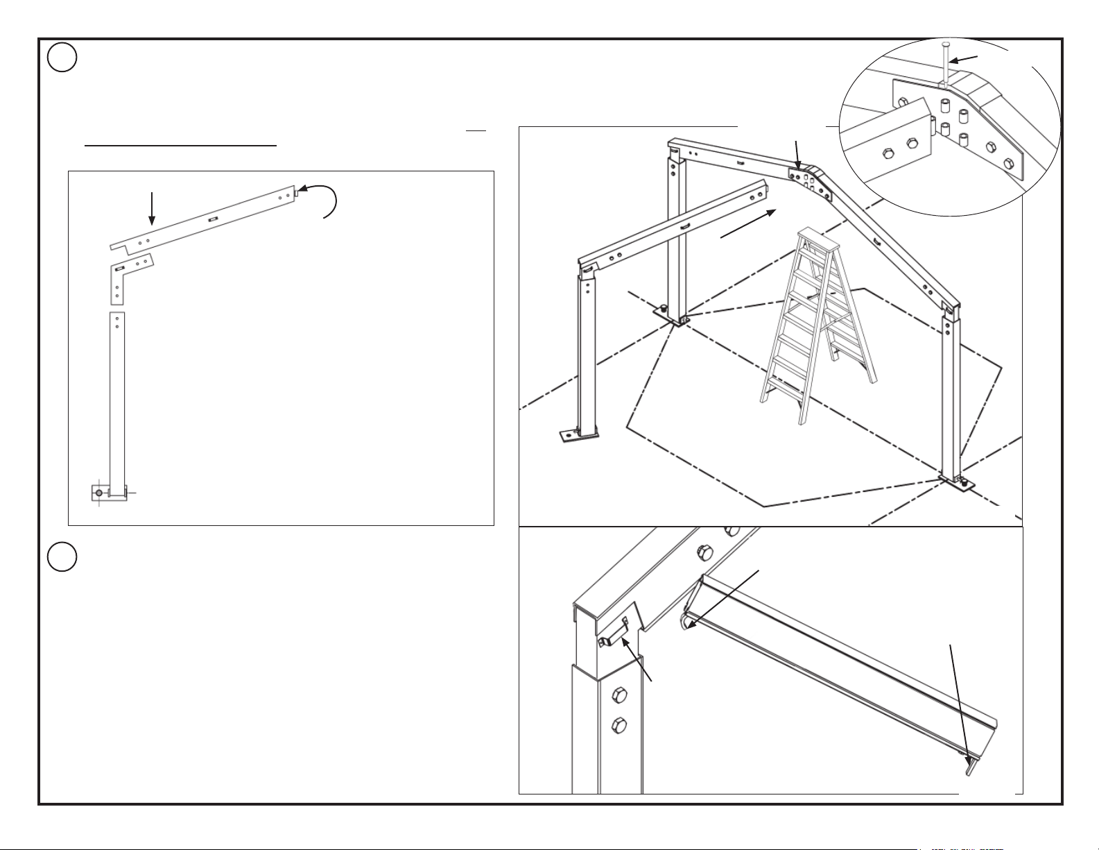
Assemble main arch as noted in the standard
1
PZ instruction manual.
Use (4) installers to raise beam to vertical.
After beam is raised, hold in place using (2)
installers.
PZ-Series Hex End Appendix
Baseplates must be parallel. Stake
each baseplate.
Width of Structure
(6M or 9M)
Assemble Main Arch
Place stepladder
between baseplates,
under ridge.
HEX END RIDGE PLATE. Use
only on the side of the hex end.
Both sides if this is a Hex Structure.
Hex ends may be used together or
as an end to a standard rectangular
building.
EC 4582
Main Arch
Figure 1a
PZHE 0912
Page 2
Continue holding the main arch with (2) installers.
2
Assemble wing arch just as you would assemble a standard arch,
beginning at base plate. Use (2) installers to raise arch to vertical. Move
arch to ridge and attach with pin as shown in Figure 2b.
Continue raising and attaching wing arches until they are all raised. Do
Not stake wing arches at this time.
12mm pin
Hex end Plate
Assemble wing arch
Wing arch rafter has hinge insert to
fit to Hex End Ridge plate with 12mm
pin.
Install Eave purlins all around Hex end. Insert curved tab of purlin into
3
eave bracket first, then, using a purlin fork, lift the other end of the purlin
and drop into the bracket of the adjacent arch.
Move wing arch into
place and pin at ridge
as shown.
Figure2a Figure 2b
Curved Tab
Eave Purlin
Eave bracket
Straight Tab
Figure 3a
2
Page 3

After Eave purlins are installed check that uprights are vertical. Adjust
4
where required.
Install intermediate purlins all around in the same manner that eave purlins
were installed.
After installation of purlins and checking that all uprights are vertical, stake
remaining baseplates.
Main Arch Eave Purlin
Intermediate Purlin
Upright Cross-cables are required on one bay for a hex end on a
5
rectangular frame and at every other bay on a hex tent. See Figure 5a.
Use eyebolts for connection of Cross-cables as shown on Figure 5b.
Figure 5a
Eyebolts - use in place of
the standard bolts where
required.
Figure 4a
Adjust cables using
turnbuckles.
Figure 5b
3
Page 4

Throw the snap end of a pull rope over to other side of tent at the Main Arch. Caution: Make certain area is clear so
6
as not to strike anyone while throwing the pull rope over the top.
Using a drop-cloth, lay the fabric next to the bottom of the upright on the snap side of the frame. Snap the pull rope
onto the ring near the kedar edge. One or two installers must be assigned the job to make sure the fabric does not
twist or get caught on the frame to prevent damage to fabric. Two installers pulling the fabric slowly and in unison can
pull the fabric up and over the frame.
Pull Rope
Main Arch
Pull Rope
Kedar
Figure 6b
Fabric should be loosely
stacked to permit easy
feeding into the channel.
Figure 6a
4
Page 5

After fabric is pulled into frame channels, fabric must be tensioned into place by one of two methods.
7
Figures 7a & 7b show the Tension bar method. This is the same method as shown in the standard PZ instructions.
The difference is that at the corner, a hinged tension bar will be used. See Figure 7b.
Figure 7c shows Bungee Cord method.
Hinged Tension
bar insert for
corners.
Figure 7b
Figure 7a
Bungee Cord
Bungee cord comes up over inside of
purlin and over top of purlin to catch on
hook on outside face of purlin.
Bottom of Curtain
Upright
Eave Purlin
VIEW LOOKING AT EAVE
PURLIN FROM INSIDE TENT.
Figure 7c
5
Page 6

28.2 03-04-09
FAX NUMBER
EVANSVILLE, INDIANA
812· 867· 2421
PHONE NUMBER
812· 867· 0547
CAUTION:
mined. Some soils require different staking or securing than that provided with the tent. Due to this variety of soil
conditions, these are the manufacturer’s suggested sequence of installation procedures. Anchor’s responsibility is
limited to the manufacture of the tent parts and materials. We are not responsible for methods that installers may
choose to erect and secure the tent to the ground.
the site of the tent installation. The number of stakes suggested will, in many cases, keep the tent erected, howev-
er, due to various soil conditions; these stakes will be insufficient to keep the tent secure in high winds. It is the tent
installer’s responsibility, not the manufacturer, to determine the appropriate number of stakes to meet the necessary
wind loads on the site. Regardless of the number of stakes we suggest, we make no representation or warranty as
to whether this specific number of stakes will meet the local tent code. Anchor does not, nor can it make any sug-
gestions, representation, or warranties about the adequate staking required at each specific installation site. Staking
information provided in the installation instructions is not a suggestion about what is necessary to meet a site-specific
load.
For additional important information, consult: “The IFAI Procedural Handbook For the Safe Installation and Mainte-
nance of Tentage” and the IFAI Pocket Guide “Pullout Capacity of Tent Stakes”, both available from the IFAI Tent
Rental Division or on our website.
tion guidelines. It is the responsibility of the tent installer/maintainer to determine the severity of the weather, prop-
er time and method of installation and/or erection and disassembly. Note: We recommend that snow and ice be
removed from the tent surface as soon as possible because accumulation will damage the tent or fabric structure.
Please consult with our Engineering Department about the maximum loads for each product.
This product has been manufactured for use as a temporary structure. For the safety of all occupants, evacuation is
recommended if threatening weather occurs, or if there is any doubt concerning the safe use of this product.
ful evaluation be made to determine safety equipment needed, such as hard hats, steel-toe shoes, safety glasses
and other as required. It is our desire that all installations are safe. Please be aware of hidden dangers both under-
ground, i.e., gas lines, water lines, electrical lines, etc. and above the tent such as power lines and telephone lines.
Anchor products are of superior design and operate best within the parameters of these instructions. It is imperative
that the instructions be carefully read and COMPLETELY FOLLOWED. Please read installation instructions before the
installation or removal of this product. Installation instructions are available online at www.anchorinc.com or by calling
1-800-544-4445.
1. For each installation, the installer is solely responsible for evaluating the site and the proper securing method deter-
2. The number of stakes suggested in the installation instructions do not necessarily meet all or any relevant codes on
3. Inasmuch as the weather is unpredictable, good judgment and common sense must be incorporated within installa-
4. Proper safety equipment should be used at all times to insure a safe installation and take down. We suggest a care-
5. Anchor stands behind its products in accordance with its standard Terms and Conditions of sale. A copy of our
Terms and Conditions of Sale can be obtained by contacting Anchor at the telephone number and/or address on this
document.
6
 Loading...