

Page 1
ProLink 500™ Wireless Intercom Owners Manual
MADE IN USA
A Message from the President
Congratulations on purchasing an Anchor Audio intercom
system, the choice of thousands of satisfied customers
including the White House, prestigious universities, school
districts nationwide, police and fire departments, and all
branches of the U.S. Military. Our products are made of the
finest materials and built with pride in the U.S.
We’ve incorporated the latest technology into your intercom
system yet kept it simple to use. Just take a few minutes to review
this manual to ensure the maximum enjoyment of your Anchor
system. Or, you can view a demonstration video complete with a trouble shooting
section at www.anchoraudio.com.
Feel free to call our friendly customer support staff at 1-800-ANCHOR1
with any questions. We love to hear from our customers.
Janet Jacobs, President
on behalf of all Anchor employees
CONTENTS
GETTING STARTED ................................................................................................................. 1
DEFINITIONS/APPLICATIONS / SYSTEM RANGE / RECHARGEABLE BATTERIES ............................ 2
BASIC SYTEM SETUP / BELT PACK CONTROLS / BLUETOOTH SETUP ......................................... 3
FREQUENTLY ASKED QUESTIONS ............................................................................................. 4
IMPORTANT SAFETY INSTRUCTIONS ........................................................................................ 4
TROUBLESHOOTING / TECHNICAL SPECS ................................................................................. 6
TWO YEAR WARRANTY
GETTING STARTED
Please check your new unit carefully for any
damage which may have occurred during shipment.
Each Anchor product is carefully inspected at the
factory and packed in specially designed boxes for
safe transport.
Notify the freight carrier immediately of any damage
to the shipping box or product. Repack the unit
in the original box and wait for inspection by the
carrier’s claim agent. Notify your dealer of the
pending freight claim.
NOTE: All damage claims must be made with freight carrier!
RETURNING SYSTEMS FOR SERVICE
OR REPAIR
For service or repair, please contact the dealer
you purchased your system from or visit
www.AnchorAudio.com to fill out an
RA
(Return Authorization)
still under warranty, you will receive an RA Number
with instructions to follow. All shipments to Anchor
Audio must include an RA number and must be
shipped prepaid. C.O.D. shipments and shipments
without an RA number will be refused and returned
at your expense.
IMPORTANT: Save the shipping box & packing materials,
they were specially designed to ship your unit!
The ProLink 500 comes with a two year warranty.
form. If your system is
For System Setup & Operation Videos Visit Our Website: www.anchoraudio.com
1
Page 2
ProLink 500™ Wireless Intercom Owners Manual
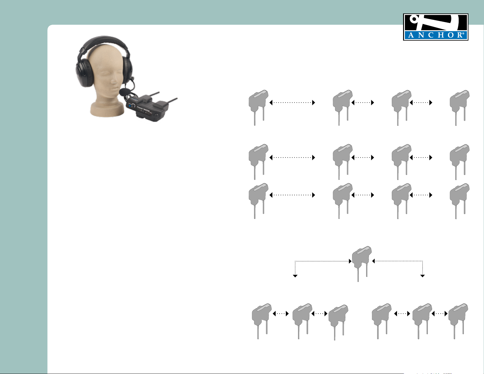
DEFINITIONS AND APPLICATIONS
ProLink 500 - wireless duplex intercom system
ProLink 500 Network - requires a MASTER belt pack and includes up to three REMOTE belt packs
(option of unlimited number of “Listen Only” beltpacks)
Channel - A or B channel selection for different applications
MASTER
BP-500M
Channel A
EXAMPLE 1 - One network
REMOTE 1
BP-500R
Channel A
REMOTE 2
BP-500R
Channel A
MADE IN USA
TWO YEAR WARRANTY
REMOTE 3
BP-500R
Channel A
WHAT IS PROLINK 500™?
ProLink is a digital wireless, full duplex intercom system that is easy to configure and
easy to operate. You can operate the MASTER belt pack with up to three REMOTE
belt packs which are identified on the side label as R1, R2 or R3. You may also have
an option of unlimited number of “Listen Only” beltpacks.The transmitter and receiver
operate in the license free 902-928 MHz range without the need for a base station.
SYSTEM RANGE
The RF signal will travel through many solid objects. However, the more solid
objects between the belt packs, the more the range will be reduced. When the belt
packs are transmitting, the Transmit LED will flash red. If the signal drops out, the
LED will glow solid red on REMOTE belt packs only. If the belt packs are too far
apart, the REMOTE belt packs need to move closer to the MASTER belt pack.
RECHARGEABLE BATTERIES
ProLink 500 belt packs include three “AA” rechargeable batteries and AC gang charger.
Fully charged batteries yield approximately five hours of continuous use. Alkaline batteries
can be used. Connecting the AC charger to a belt pack with alkaline batteries installed
could seriously damage the system.
INSTALL BATTERIES
1. Remove battery door
2. Install three “AA” NiMH batteries
3. Replace battery compartment door
CHARGE BATTERIES
1. Connect gang charger (included) into charging port on the bottom of the belt packs
2. Plug gang charger into AC outlet for minimun
of five hours
LED ON = battery charging
LED OFF = battery charged
EXAMPLE 2 - Two independant networks in the same facility
MASTER
BP-500M
Channel A
MASTER
BP-500M
Channel B
REMOTE 1
BP-500R
Channel A
REMOTE 1
BP-500R
Channel B
REMOTE 2
BP-500R
Channel A
REMOTE 2
BP-500R
Channel B
REMOTE 3
BP-500R
Channel A
REMOTE 3
BP-500R
Channel B
EXAMPLE 3 - Director or coach talking and listening between two channels
requires the following configuration
Head coach or director toggles between Channel
A and Channel B for conversations between a two
ProLink networks
MASTER
BP-500M
Channel B
CHANNEL B
REMOTE 2
BP-500R
Channel B
REMOTE 3
BP-500R
Channel B
MASTER
BP-500M
Channel A
CHANNEL A
REMOTE 2
BP-500R
Channel A
REMOTE 1
REMOTE 3
BP-500R
Channel A
BP-500R
CAUTION: Do not attempt to charge alkaline batteries.
Some users are required (for emergency preparedness, etc.) to leave their
ProLink 500 units plugged into the charger at all times.
For those applications we recommend replacing the batteries every 12
months.
For System Setup & Operation Videos Visit Our Website: www.anchoraudio.com
This is an assigned group such as the
offense coach or lighting crew
This is an assigned group such as the
defense coach or sound crew
2
Page 3

ProLink 500™ Wireless Intercom Owners Manual
MADE IN USA
BASIC SETUP AND OPERATION
1. Charge the batteries 5-6 hours.
Note: Belt packs operate about ten to twelve hours of
continuous use per charge. (Diagram 2)
2. Find the MASTER belt pack as indicated on the top label. The
Master belt pack must be ON for each of the REMOTE belt
packs to function. (Diagram 1)
3. Plug headset cable into belt pack & adjust boom. (Diagram 2)
4. Turn on power and set headset volume. Power ON LED is
solid green and flashing green for LOW battery. (Diagram 1)
5. Set slide switch to Push to Talk or Always On mode.
(Diagram 3)
6. Choose channel A or B for all belt packs. If both channels are
used at the same time, two master belt packs are required
(See page 6). (Diagram 1)
Note: repeat above for each member’s belt pack in use.
BELT PACK CONTROLS
Mic Gain – controls the microphone sensitivity. Someone with a soft
voice will increase the Mic Gain.
Power Knob also controls headset volume. The Power LED is solid
green while ON and flashes green when batteries need recharging.
A/B Channel Selection – each member of the system must be on the
same channel to hear communication
RX/TX LED – flashes RED when transmitting and is SOLID RED on the
Remote belt packs when out of range of the Master belt pack
PTT control – push to engage in conversation and release when done
Push to Talk or Always ON slide switch for the mode of operation
preferred. If you want hands free operation, select the Always On mode.
Your belt pack is live at all times.
4-PIN XLR headset connector - use Anchor Audio headsets or any
headset with a dynamic microphone.
Charging Port for the GC-9000 gang charger – charge LED glows RED
when charging and stops glowing when charge complete.
HEADSETS
ProLink 500 uses noise cancelling headsets with a 4-pin XLR connector.
Models H-2000 (dual ear muff) and H-2000S (single ear muff) are
available. The headsets include an adjustable boom microphone.
TWO YEAR WARRANTY
DIAGRAM 1
ON/OFF/VOLUME CONTROL
MIC GAIN CONTROL
PROLINK 500 BELT PACK
Model Shown: BP-500M
POWER LED (GREEN)
CHARGING LED (RED)
RX/TX LED (RED)
CHANNEL SELECTOR
DIAGRAM 2
“PUST TO TALK “ BUTTON
“PUST TO TALK “ OR
ALWAYS ON SLIDE SWITCH
XLR CONNECTOR
CHARGING PORT
DIAGRAM 3
BLUETOOTH SETUP
1. Turn ON the BT headset and put it in pairing mode to pair (“CONNECT”) with ProLink 500 beltpack.
Note: Every Bluetooth headset has its own pairing procedure. Refer to instructions.
2. The BT will auto pair with the ProLink 500 if the BT headset has been already paired to the ProLink 500 beltpack.
3. RED LED will turn ON (see on the back side of ProLink 500) in a few seconds indicating that it has paired.
4. After the RED LED turns ON push the CONNECT button to activate the audio.
5. If you want to switch to the wired headset on the same beltpack you will have to turn
OFF/disconnect the BT headset.
6. If you want to pair a new BT headset push “DISCONNECT” to delete current pairing before you start the pairing process.
BELT CLIP
BLUETOOTH
PAIRING
PANEL
BATTERY COMPARTMENT
For System Setup & Operation Videos Visit Our Website: www.anchoraudio.com
3
Page 4

ProLink 500™ Wireless Intercom Owners Manual
FREQUENTLY ASKED QUESTIONS
MADE IN USA
TWO YEAR WARRANTY
Can I use my own headset?
Yes. The ProLink 500 is designed to work with dynamic microphone elements.
(Shields can be connected to chassis ground pin.)
Headset pin configuration: 1=Mic(-), 2=Mic(+), 3=Headphone(-), 4=Headphone(+)
I’ve run out of battery life, now what?
You can substitute “AA” alkaline batteries rechargeable batteries. However, connecting
the charger to the belt pack when alkaline batteries are installed could seriously damage
your belt pack.
Can my ProLink 500 work with other wireless intercom systems?
No. ProLink 500 uses proprietary design and software exclusive to the product.
Can my ProLink 500 work with wired intercom systems?
Yes. ProLink 500 uses WingMAN 500 as a modular link to PortaCom and other two-wire
intercoms.
Can someone eavesdrop on my conversation?
The proprietary software makes it difficult for anyone to penetrate the wireless network.
Anchor offers an encrypted model for additional security.
If I break my headset, what do I do?
The H-2000 and H-2000S headsets are covered by a 2-year warranty. Follow the
instructions in the Getting Started section on page 2 for Return Authorization. ProLink
500 headsets are sold separately if a replacement is needed.
Can I add belt packs to my network?
Your intercom network can operate with one Master belt pack and up to three REMOTE
belt packs. You may also add unlimited number of “Listen Only” beltpacks.
This device complies with part 15 of the FCC Rules. Operation is subject to the following
two conditions: (1) This device may not cause harmful interference, and (2) this device must
accept any interference received, including interference that my cause undesired operation.
“This device has been designed to operate with a 1/2 wavelength dipole antenna with
RPSMA connector, and having a maximum gain of 1.17dB. Antennas not included in this
list or having a gain greater than 1.17dB are strictly prohibited for use with this device. The
required antenna impedance is 50 ohms.”
“To reduce potential radio interference to other users, the antenna type and its gain should
be so chosen that the equivalent isotropically radiated power (e.i.r.p.) is not more than that
permitted for successful communication.”
“Operation is subject to the following two conditions: (1) this device may not cause
interference, and (2) this device must accept any interference, including interference that
may cause undesired operation of the device.”
Newsroom Studio
Control Room
PortaCom
Wired Intercom System
(Up to 20 Headsets)
WingMAN (Master)
ProLink
R2
ProLink
R1
ProLink
R3
Example of ProLink 500 & PortaCom using WingMan Interface System
For System Setup & Operation Videos Visit Our Website: www.anchoraudio.com
News Stage
4
Page 5

ProLink 500™ Wireless Intercom Owners Manual
Important Safety Instructions
1) Read Instructions – All the safety and operation instructions should be read before the
product is operated.
2) Retain Instructions – The safety and operating instructions should be retained for future
reference.
3) Heed Warnings- All warnings on the product and in the operating instructions should be
adhered to.
4) Follow Instructions – All operating and use instructions should be followed.
5) Cleaning – Unplug this product from the wall outlet before cleaning. Do not use liquid
cleaners or aerosol cleaners. Use a damp cloth for cleaning.
Exception: A product that is meant for uninterrupted service and that for some specific
reason, such as the possibility of the loss of an authorization code for the CATV converter,
is not intended to be unplugged by the user for cleaning or any other purpose, may
exclude the reference to unplugging the product in the cleaning description otherwise in
above 5).
6) Attachments – Do not use attachments not recommended by the product manufacturer
as they may cause hazards.
7) Water and Moisture – Do not use this product near water – for example, near a bath tub,
wash bowl, kitchen sink, or laundry tub; in a wet basement; or near a swimming pool;
and the like.
8) Accessories – Do not place this product on an unstable cart, stand, tripod, bracket, or
table. The product may fall, causing serious injury to a child or adult, and serious damage
to the product. Use only with a cart, stand, tripod, bracket, or table recommended by the
manufacturer, or sold with the product. Any mounting of the product should follow the
manufacturer’s instructions, and should use a mounting accessory recommended by the
manufacturer.
9) A product and cart combination should be moved with care. Quick stop, excessive force,
and uneven surfaces may cause the product and cart combination to overturn.
10) Ventilation – Slots and openings in the cabinet are provided for ventilation and to ensure
reliable operation of the product and to protect it from overheating, and these openings
must not be blocked or covered. The openings should never be blocked by placing the
product on a bed, sofa, rug, or other similar surface. This product should not be placed in
a build-in installation such as a bookcase or rack unless proper ventilation is provided or
the manufacturer’s instructions have been adhered to.
11) Power Sources – This product should be operated only from the type of power source
indicated on the marking label. If you are not sure of the type of power supply to your
home, consult your product dealer or local power company. For products intended to
operate from battery power, or other sources, refer to the operating instructions.
12) Grounding or Polarization – This product may be equipped with a polarized alternatingcurrent line plug (a plug having one blade wider than the other). This plug will fit into
the power outlet only one way. This is a safety feature. IF you are unable to insert the
plug fully into the outlet, try reversing the plug. If the plug should still fail to fit, contact
your electrician to replace your obsolete outlet. Do not defeat the safety purpose of the
polarized plug.
13) Power-Cord Protection – Power-supply cords should be routed so that they are not likely
to be walked on or pinched by items placed upon or against them, paying particular
attention to cords at plugs, convenience receptacles, and the point where they exit from
the product.
14) Protective Attachment Plug – The product is equipped with an attachment plug having
overload protection. This is a safety feature. See Instruction Manual for replacement or
resetting of protective device. If replacement of the plug is required, be sure the service
technician has used a replacement plug specified by the manufacturer that has the same
overload protection as the original plug.
For System Setup & Operation Videos Visit Our Website: www.anchoraudio.com
15) Outdoor Antenna Grounding – If an outside antenna or cable system is connected to
16) Lightning – For added protection this product during lightning storm, or when it is left
17) Power Lines – An outside antenna system should not be located in the vicinity of
18) Overloading – Do not overload wall outlets, extension cords, or integral convenience
19) Object and Liquid Entry – Never push objects of any kind into this product through
20) Servicing – Do not attempt to service this product yourself as opening or removing
21) Damage Requiring Service – Unplug this product from the wall outlet and refer servicing
a. When the power-supply cord or plug is damaged.
b. If liquid has been spilled, or objects have fallen into the product.
c. If the product has been exposed to rain or water.
d. If the product does not operate normally by following the operating
e. If the product has been dropped or damaged in any way.
f. When the product exhibits a distinct change in performance – this indicates a
22) Replacement Parts – When replacement parts are required, be sure the service
23) Safety Check – Upon completion of any service or repairs to this product, ask the service
24) Wall or Ceiling Mounting – The product should be mounted to a wall or ceiling only as
25 Heat – The product should be situated away from heat sources such as radiators, heat
MADE IN USA
TWO YEAR WARRANTY
the product, be sure the antenna or cable system is grounded so as to provide some
protection against voltage surges and built-up static charges. Article 810 of the National
Electrical Code, ANSI/NFPA 70, provides information with regard to proper grounding of
the mast and supporting structure grounding of the lead in wire to an antenna discharge
unit, size of grounding conductors, location of antenna-discharge unit, connection of
grounding electrodes, and requirements for the grounding electrode. See Figure A.
unattended and unused for long periods of time, unplug it from the wall outlet and
disconnect the antenna or cable system. This will prevent damage to the product due to
lightning and power-line surges.
overhead power lines or other electric light or power circuits, or where it can fall into
such power lines or circuits. When installing an outside antenna system, extreme care
should be taken to keep from touching such power lines or circuits as contact with them
might be fatal.
receptacles as this can result in a risk of fire or electric shock.
openings as they may touch dangerous voltage points or short-out parts that could result
in a fire or electric shock. Never spill liquid of any kind on the product.
covers may expose you to dangerous voltage or other hazards. Refer all servicing to
qualified service personnel.
to qualified service personnel under the following conditions:
instructions. Adjust only those controls that are covered by the operating
instructions as an improper adjustment of other controls may result in damage
and will often require extensive work by a qualified technician to restore the
product to its normal operation.
need for service.
technician has used replacement parts specified by the manufacturer or have the same
characteristics as the original part. Unauthorized substitutions may result in fire, electric
shock, or other hazards.
technician to perform safety checks to determine that the product is in proper operation
condition.
recommended by the manufacturer.
registers, stoves, or other products (including amplifiers) that produce heat.
5
Page 6

ProLink 500™ Wireless Intercom Owners Manual
MADE IN USA
TWO YEAR WARRANTY
TROUBLESHOOTING
Can’t hear a person speaking?
First, verify that the MASTER belt pack is ON and within range of each of the REMOTE belt packs.
Second, increase headset volume using the headset volume knob on the top of the belt pack. In
extremely loud environments, you will need to use the dual ear muff headset with noise cancelling
properties. If you still can’t hear, your batteries may be dead. Also, verify each belt pack is on the
same channel.
Microphone not picking up your voice?
First, adjust the microphone sensitivity setting on the top of the belt pack by turning the blue button
incrementally until you reach desired sensitivity level. Move the microphone closer to your mouth
and speak up clearly. For example, some people speak softer than others and need a more sensitive
microphone level.
Background noise transmitting across system?
Reduce the microphone sensitivity setting by turning the blue button until you reach the desired level.
Transmission is weak?
Your rechargeable batteries may be running low. If batteries are weak, the green LED on the top panel
will flash. Your belt pack batteries need to be recharged. If you need to keep working, you can use
disposable alkaline batteries.
Proper intercom usage
Up to 4 people may talk at once. Use proper intercom etiquette – don’t “talk over” others while they
are speaking. Also, position the microphone to pick up a minimum of breath noise.
PROLINK 500 TECHNICAL SPECIFICATIONS
ProLink Belt Pack (BP-500)
RF Frequency Range 902-928MHz
Modulation FSK
Range (line of sight) Duplex 500’ / 75 m
Antenna 1/2 - wavelength dipole
Power Supply 9VDC, 1.2ADC
Battery Life 12 hours
Weight 15oz. / 0.42kg (with batteries)
Dimensions 4.5 “x 6.25” x 3.75”
(114.3 x 158.75 x 95.25 mm)
Single-Ear (H-2000S & Dual-Ear Headphones H-2000)
Drivers Dynamic, 40mm
Impedance 300W +/- 15%
Frequency Response 20Hz - 20kHz
SPL 91dB +/- 3dB
Rated Power > 40mW
Distortion < 5%
Microphone Dynamic, Uni-directional,
Low impedance
Mic Sensitivity Referenced to 0dB=1V/μbar, 1kHz
Min -85 dB / Typical -83 dB /
Max -81 dB
Frequency Response 200Hz-12kHz
Connector Plug 4-pin XLR, female
Weight Single: 13 oz. / 0.37 kg
Dual: 16 oz. / 0.45 kg
FCC ID: J8ZBP-500
Warning: Changes or modifications not expressly approved by Anchor Audio, Inc.
could void the user’s authority to operate this device. Only use the provided belt-clip.
For System Setup & Operation Videos Visit Our Website: www.anchoraudio.com
(Specifications Subject to Change Without Notice)
ANCHOR AUDIO CUSTOMER SERVICE
800.262.4671
FOR ADDITIONAL INFORMATION
visit www.anchoraudio.com
6
 Loading...