

Page 1

POOL COVER
MEASURING INSTRUCTIONS
IMPORTANT NOTE: Failure to provide all information requested will extend the order process and may result in return
trips to the pool for further information.
1100 Burch Dr. • P.O. Box 3477
Evansville, IN 47733 U.S.A.
Ph. (812)867-2421
Fax (812)867-1429
E-mail: custdiv@anchorinc.com
1. SKETCH Begin with a freehand sketch indicating the inside pool edge (water edge). Include in your sketch the
deck area, planters and any obstructions within 3 feet of the pools waterline. Photos of pool are required as indicated
below.
2. A-B POINTS - See Figure 1 Establish two points to be referred to as “A-B” points. The “A” should be
on the left and the “B” on the right while facing the pool (If A and B points are fl ipped the cover may be made upside
down). The “A-B” line must be at least 3 feet away (the further away, the better) from the water’s edge of the pool
and 2/3 the length of the pool; the longer the “A-B” line, the better. (show your “A-B” points and their location on your
sketch).
NOTE: The “A-B” line must never cross the pool line and should be at least 3 feet away from the pool at the closest
point.
3. A-B MEASUREMENTS
A. POOL:
● Using chalk, mark and NUMBER points along the water’s edge of pool at approximately 3’-0” intervals
or less for tight radius areas (4 foot radius or less) use intervals of 6 inch to 1 foot apart. All corner/direction
changes must be marked and numbered.
● Measurements are then to be taken from point “A” to point #1, then point #2 and so on to each numbered
point around the pool. Then measure from point “B” to point #1, then point #2 as previously done for point “A”.
Measurements are to be rounded to the nearest inch and listed in column format as shown in the example.
B. SPECIAL FEATURES / OBSTRUCTIONS:
● Using chalk, mark and LETTER points that include all corner/direction change, ladders, handrails, grab
rails, slide legs, rocks, spillways, spa walls separating spa and pool, fi ll spout and dive stand. These areas
require closer intervals of 6 inches to 1 foot apart. At least 3 points should be marked and given along
straight walls.
● Measurements are then to be taken from point “A” to Letter A, then Letter B and so on to each Lettered point
around the pool. Then measure from point “B” to Letter A, then Letter B as previously done for point “A”.
Measurements are to be rounded to the nearest inch and listed in column format as shown in the example.
4. FOR QUOTING Measure to the longest length and widest width of the pool between two known points and
record these measurements and points in table.
5. CROSS REFERENCE DIMENSIONS Measurements are to be taken for reference of the length and
width between two known cross points and recorded in table. Additional measurements are suggested for more
diffi cult or custom pools (three width & two length). Cross dimensions to any obstacles or complicated areas is also
recommended.
IMPORTANT NOTES:
● ALL A-B MEASUREMENTS MUST BE MEASURED AT THE SAME ELEVATION (See Appendix C)
● Indicate on diagram where there is less than 3 Ft. of Decking.
● Use of stakes over 10 ft. in continuous length or over 10% maximum perimeter of cover does not meet ASTM
standards for safety cover.
● Please mark any obstruction measured that is not on water line with LETTERS A, B, C….
PCMI 0812EC4572
Page 2
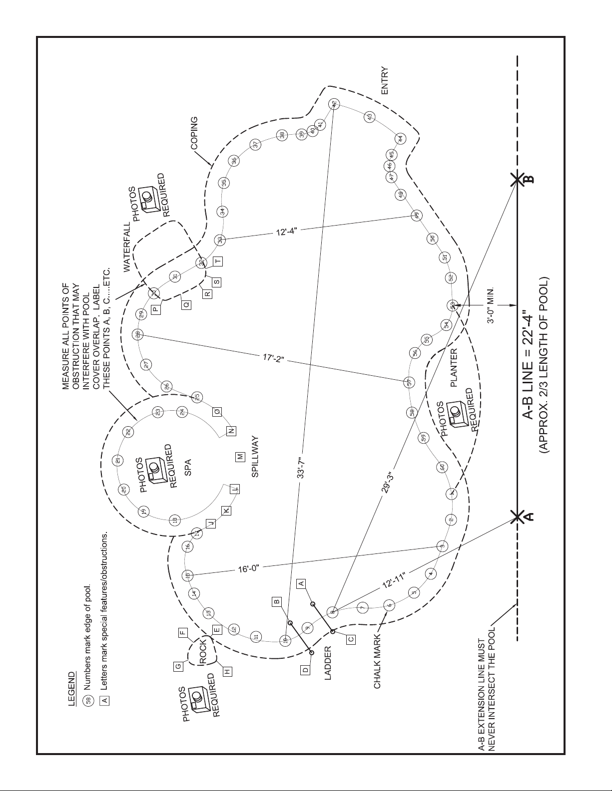
Figure 1
FOR REFERENCE ONLY.
2
Page 3

PROVIDE SKETCH OF POOL BELOW
ADDITIONAL NOTES OR COMMENTS:
PROVIDE SKETCH OF POOL BELOW
Dealer Name____________________________
Customer Name _________________________
Date___________________________________
____________________________________________________________________________________________________________________
____________________________________________________________________________________________________________________
____________________________________________________________________________________________________________________
____________________________________________________________________________________________________________________
____________________________________________________________________________________________________________________
____________________________________________________________________________________________________________________
____________________________________________________________________________________________________________________
FAILURE TO PROVIDE ALL INFORMATION REQUESTED WILL EXTEND THE ORDER PROCESS AND MAY
RESULT IN RETURN TRIPS TO THE POOL FOR FURTHUR INFORMATION.
3
Page 4
Q
A-B TABLE
1
2
3
4
5
6
7
8
9
10
11
12
13
14
15
16
17
18
19
20
21
22
23
24
25
26
27
28
29
30
Dealer Name____________________________
Customer Name _________________________
Date___________________________________
REFERENCE DIMENSIONS
AB AB AB
31
32
33
34
35
36
37
38
39
40
41
42
43
44
45
46
A
B
C
D
E
F
G
H
I
J
K
L
M
N
O
P
47
48
49
50
51
52
53
54
55
56
57
58
59
60
R
S
T
U
V
W
X
Y
Z
AA
AB
AC
AD
Distance between A and B points:_________________
If more numbers are required, see Appendix E.
LENGTH AND WIDTHS: OBSTRUCTIONS:
(THIS HELPS DETECT MEASURE PROBLEMS)
FROM PT ________ TO PT ________ = _________ _____________ AT PT________TO PT _______
PT ________ TO PT ________ = _________ _____________ AT PT________TO PT _______
PT ________ TO PT ________ = _________ _____________ AT PT________TO PT _______
PT ________ TO PT ________ = _________ _____________ AT PT________TO PT _______
PT ________ TO PT ________ = _________ _____________ AT PT________TO PT _______
PT ________ TO PT ________ = _________ _____________ AT PT________TO PT _______
FAILURE TO PROVIDE ALL INFORMATION REQUESTED WILL EXTEND THE ORDER PROCESS AND MAY
RESULT IN RETURN TRIPS TO THE POOL FOR FURTHUR INFORMATION.
(OBSTRUCTION)
(OBSTRUCTION)
(OBSTRUCTION)
(OBSTRUCTION)
(OBSTRUCTION)
(OBSTRUCTION)
4
Page 5

Circle Correct Answers.
Fill In applicable blanks.
Dealer Name____________________________
Customer Name _________________________
Date___________________________________
REQUIRED INFORMATION
1. Are there any non-removable handrail, grab rails, or ladders?
A. ‘A-B’ dimensions are required to front center of all rails at the horizontal plane of coping.
B. Distance rails are set back from pool
2. Is there a non-removable fill spout?
A. ‘A-B’ dimensions needed for start and end of pipe.
B. Fill spout is: Level with deck Raised
● If raised, distance set back from pool?____________
C. Is end of spout below coping? YES NO
● Distance set in to pool?___________
3. Is there a dive stand?
A. Distance set back from pool?___________
B. ‘A-B’ Measure the base.
C. Is Anchor’s diving board harness required? YES NO
4. Are there dive rock(s)? If yes, See Appendix A
YES NO
YES NO
YES NO
YES NO
5. Are there slide legs within 2’ of pool?
If yes, give ‘A-B’ dimensions to each leg, and give the distance each is set back from pool
6. Is there a spa? If yes, See Appendix B
Is spa to be included in the quote / order? YES NO
YES NO
YES NO
5
Page 6

Circle Correct Answers.
Fill In applicable blanks.
Dealer Name____________________________
Customer Name _________________________
Date___________________________________
REQUIRED INFORMATION CONT’D
8. Is there a planter or grass area?
A. If yes, PHOTOS REQUIRED. Give ‘A-B’ dimensions Pts _______ to ______
B. Installation method in planters.
● Ground tubes – see IFAI soil classifi cations available on anchor’s website (www.
anchorinc.com).
● *Stakes
*
Continuous length of staked perimeter must not exceed 10% of pool
or no more than 10ft. Failure to follow this rule will invalidate your
warranty and cover will not meet ASTM standards for safety covers.
9. Is there a raised wall or raised planter? If yes, see Appendix C
10. Is there a waterfall or rock formation?
A. If yes, PHOTOS REQUIRED.
B. ‘A-B’ the beginning, end, front and sides of the formation, as well as pool edge in 1’-0”
intervals.
YES NO
YES NO
YES NO
C. Is waterfall or rock formation able to be anchored into? YES NO
D. Distance rocks hang over pool edge? ______________
11. Are there varying deck levels? If yes, see Appendix C
12. Is there a negative edge? If yes, see Appendix D
YES NO
YES NO
6
Page 7

APPENDIX
Reinforcement at
rock edges.
Pool Edge
Appendix A - Dive Rocks
Dealer Name____________________________
Customer Name _________________________
Date___________________________________
1. PHOTOS REQUIRED.
A. ‘A-B’ sides and front of rock, as well as pool edge using 6” intervals. Pts______to ______
B. Cover Options:
Up & Over - See Figure A-1
●
What is the height (18” maximum) and width of the rock at the up & over
area?_________
If wedges are required give sizes for wedges.________________
● Cable Construction - See Figure A-2
Does Rock overhang the pools edge? YES NO
Distance Rock hangs over edge. __________
Does Rock extend below deck level? YES NO
Rock extends below deck level from Pts. ________to__________
● Web in Pocket - See Figure A-3
Perimeter around rock? _____________
Does rock extend below deck level? YES NO
Rock extends below deck level from Pts. ________to__________
Figure A-1
DIVE ROCK WITH UP & OVER POOL
COVER CONSTRUCTION
A
Reinforcement at
rock edges.
14
13
11
Pool Edge
12
17
16
B
C
Wedge
15
Wedge
Height (must
not exceed 18”)
Dive Rock
Tye clip
Wedge
Clips
7
Page 8

Figure A-2
Pool Edge
DIVE ROCK WITH CABLE CONSTRUCTION
Dealer Name____________________________
Customer Name _________________________
Date___________________________________
Dive Rock
16
14
15
17
Overhang
Distance
A
B
Cable Construction
C
Figure A-3
DIVE ROCK WITH WEB-IN-POCKET CONSTRUCTION
18
19
12
Pool Edge
13
Web Pocket - Runs
under rock to other
Dive Rock
side of rock.
15
Web with Ratchet - Need
distance around Dive Rock
14
to determine length of web
with Ratchet.
A
B
C
16
17
18
8
Page 9

Appendix B - Spa Cover
1. PHOTOS REQUIRED
A. Cover Options:
Dealer Name____________________________
Customer Name _________________________
Date___________________________________
Separate cover?
●
If yes, ‘A-B’ spa and indicate points with Letters on chart and drawing.
Is spa to be accessible year round? YES NO
Cable Construction - See Figure B-1?
●
If yes, is spa wall able to be anchored into? YES NO
Indicate where cable is to be located. Pts___________to___________
Cable in Pocket - See Figure B-2?
●
If yes, indicate where Pocket is to be located. Pts__________to___________ YES NO
Web in Pocket - See Figure B-3 (only available on round or oval)
●
If yes, perimeter around spa? _____________ YES NO
Indicate where Pocket is to be located. Pts__________to___________ YES NO
One cover for pool and spa?
●
Up & Over (18” maximum height)...If yes:
What is the height of the spa above deck level?______________
YES NO
YES NO
YES NO
YES NO
If more than one elevation, give points and height at elevation change._________
If wedges are required give sizes and quantities for wedges.________________
B. Does spa have an
● If yes, ‘A-B’ dimensions required to locate spillway.
5-Star cover w/ drains, are drain panels wanted in spa area?
C. If
D. Are there any other specifi c spa cover design instructions? YES NO
● Please specify. _______________________________________________________
open spillway?
YES NO
YES NO
9
Page 10

Pool Edge
Figure B-1
Pool Edge
Cable Pocket
SPA WITH CABLE CONSTRUCTION
Dealer Name____________________________
Customer Name _________________________
Date___________________________________
A
12
11
Figure B-2
SPA WITH CABLE POCKET
12
14
13
15
14
Cable Construction
16
B
16 17
Pool Edge
15
Dealer Name____________________________
Customer Name _________________________
Date___________________________________
Cable Pocket
Pool Edge
17
18
20
13
19
Cable w/turnbuckle - hooked
to eyebolt anchored with
threaded drop-in anchor.
Cable attached to anchor bolt.
Cable Pocket Length not to exceed 18’-0”. External curves are not allowed. Straight lines are not allowed. Shallow internal, smooth
curved areas, where the cable is close to being pulled straight are not allowed. Only internal, smooth curved areas are allowed. (NO
SHARP CORNERS)
10
Page 11

Pool Edge
Figure B-3
SPA WITH WEB IN POCKET
Dealer Name____________________________
Customer Name _________________________
Date___________________________________
12
13
G
15
14
F
E
16
D
17
18
A
B
C
19
Pool Edge
20
Web with Ratchet - Need
distance around spa to
determine length of web with
Ratchet.
11
Page 12

Dealer Name____________________________
Appendix C - Raised Areas or Varying
Deck Levels
Customer Name _________________________
Date___________________________________
1. PHOTOS REQUIRED FOR EACH RAISED AREA OR VARYING DECK
LEVEL.
A. For Raised Walls - See Figure C-1
● Is wall able to be anchored into? YES NO
● ‘A-B’ the beginning and end of the raised areas, as well as 1’-0” intervals along raised
area.
● Height of wall? ___________
B. For
varying deck levels - See Figure C-1
● Indicate height of each level change, and ‘A-B’ each level including points on risers to
indicate angles away from pool edge.
Figure C-1
RAISED AREAS OR VARYING DECK LEVELS
B
CORRECT!
A
CORRECT!
WRONG
CORRECT!
CORRECT!
WRONG
IMPORTANT NOTE: All A B Points MUST be taken on the same plane/elevation.
12
Page 13

Appendix D - Negative Edge
SEPARATE BASIN COVER
ONE-PIECE COVER
A. PHOTOS REQUIRED.
B. See Figure D-1 for additional instructions for measurement requirements.
C. Indicate construction preference.
● Make as one cover Separate Basin Cover No cover
Dealer Name____________________________
Customer Name _________________________
Date___________________________________
Figure D-1
NEGATIVE EDGE
SEPARATE BASIN COVER
ONE-PIECE COVER
CABLE ALONG BACK
WALL OF BASIN
COVER OPTIONS
13
Page 14

Appendix E
A-B TABLE cont’d
REFERENCE DIMENSIONS
14
 Loading...