

Page 1
Perfectshade®
Assembly Instructions
SALES OFFICES:
1100 BURCH DRIVE
PO BOX 3477
EVANSVILLE, IN 47733 USA
EC 3958
PHONE: 800-322-8368
or 812-867-2421
FAX: 812-867-4636
EMAIL: oad@anchorinc.com
www.anchorinc.com
PRODUCTION FACILITIES:
EVANSVILLE, IN
PS 0409
Page 2
Warning: The Perfect Shade Structure is intended for concrete Install only. Installer is solely responsible for evaluating the quality of the concrete and its suitability for this structure.
Concrete installation surface must be level.
Manpower Required:
Three experienced installers should be able to assemble any size frame with fabric in two hours.
Caution:
Please read through this assembly manual completely before beginning your installation. Be sure the proper
equipment and safety precautions are in place. We hope that you enjoy the design features of the Perfect Shade
Structure.
1. Be aware to avoid contact of frame sections with any overhead power lines near the site.
2. Consult the local utility company prior to installation in order to avoid all underground power lines and gas
lines or other utility easements.
3. Keep site clear of debris to avoid tripping, especially while carrying frame parts or bundle of fabric.
4. When moving frame sections by hand, use proper lifting techniques to protect the back, and avoid pinching
fi ngers while making hardware connections.
5. Do not drag bundle of fabric on concrete, asphalt, or ground as this can cause damage to the fabric from abrasion through the bag.
6. The installation method described here requires coordination of tasks between workers. A safe installation is
dependent on that coordination. Work cooperatively as a team.
7. This tent is manufactured for use as a temporary sun shade structure. Evacuation is recommended if threatening or windy weather occurs.
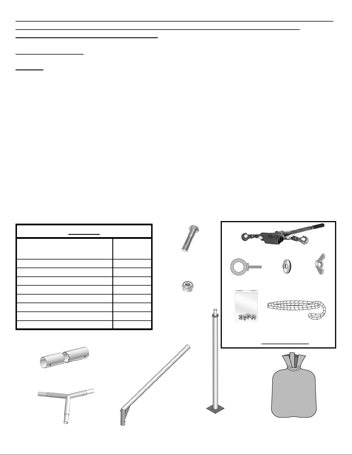
Parts List
Part Name
Upright with Base Plate 4
Hip Weldment 4
Peak Weldment 2
Ridge Tube 1
Hex Head Cap Screw 1/2 x 3 1/4” 4
1/2” Nylock Nut 4
Fabric top in bag with wire rope & clamps 1
Installation Kit (purchased separately) 1
Qty. for (1)
Frame
1/2” Hex
Head Cap
Screw
1/2” Nylock
Nut
Come-a-long (2)
Eyebolt (2) Neoprene
Washer (4)
Pull Rope (2)
(4) Wire Rope
Clamps
(spares)
Installation Kit
Wing nut
(2)
Ridge Tube
Peak Weldment
Hip Weldment
Upright with
Baseplate
Fabric top Bag
with wire rope & clamps
attached to top.
2
Page 3
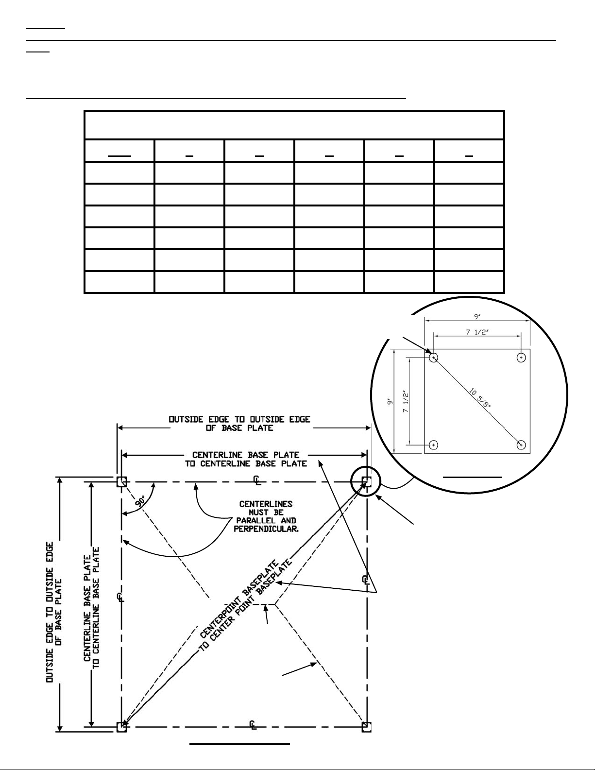
Step 1:
Choice of 1/2” diameter anchoring devices are at the discretion of the customer and not supplied by Anchor Industries.
Place anchoring devices as shown on the plan view below. (4) anchoring devices per base plate.
Note: For Your Convenience, (1) Template is supplied at the center of this manual.
DIMENSION CHART
FOR BASE PLATE LAYOUT
Size A B C D E
10’ x 10’ 9’- 10” 9’-10” 10’-7” 10’-7” 13’-10 7/8”
10’ x 15’ 14’- 10” 9’-10” 15’-7” 10’-7” 17 -9 9/16”
10’ x 20’ 19’- 10” 9’-10” 20’-7” 10’-7” 22’-1 5/8”
15’ x 15’ 14’- 10” 14’-10” 15’-7” 15’-7” 20’-11 3/4”
20’ x 20’ 19’- 10” 19’-10” 20’-7” 20’-7” 28’-0 9/16”
20’ x 30’ 29’- 10” 19’-10” 30’-7” 20’-7” 35’-9 7/8”
Caution: Concrete installation
surface must be level.
“C” Ref. dimension
Corner AA
“B”
“E” Diagonal
(4) 3/4” dia. holes for 1/2”
dia. anchoring devices.
“A”
Base Plate
Corner CC
Base Plate
(Typ. 4)
Dimensions are to center
points of base plates unless noted otherwise.
Ridge
“D” Ref. dimension
Corner BB
Frame shown in
dashed lines
Base Plate Layout
Corner DD
3
Page 4

Note the orientation of the corners to the ridge. Base plates
MUST be laid out in this order. -- AA, BB, CC and then DD.
Peak Weldments
Corner CC
Base Plate
Template
Ridge
Hip
Corner DD
Base Plate
Template
Corner BB
1st Base Plate
Template
Corner AA
2nd Base Plate
Template taped to
concrete surface.
Note: All uprights are identical, but proper orientation is
critical as noted in Step 3.
Figure 2
Step 2
Layout frame members as shown above in their approximate fi nal placement. (See base plate layout in Step 1)
Step 3
Stand one of the uprights over the installed anchors at Corner AA. (See Figure 2)
Warning: Examine the orientation of the upright so that when hip is attached it will be pointed toward the ridge. (See
Figure 3)
Step 4
Fasten the base plate to the anchors and tighten to snug. (See Figure 4)
Hip
Slide hip down
over upright aligning holes.
Note that hole thru
top of upright is
perpendicular to
hip and aligns with
hole in hip.
Upright
Figure 3
Upright
Remove template
before base plate
installation.
Figure 4
4
Page 5

Step 5
Attach the fi rst hip. Lift the Peak end of the hip up by climb-
ing a ladder (ladder placed at the approximate position of
the peak) (See Figure 5). Another person at the upright on a
ladder must direct the person at the peak end of the hip so
that it may be slipped into place on the upright. Make sure
the holes in the upright are aligned with those in the hip.
(See Figure 3) Loosely install bolt at hip to upright.
Step 6
Attach the Peak weldment to the hip. (Figure 6)
Warning: Examine the orientation of the peak weldment so
that the angles of the hips and ridge look to be pointing in
the proper directions.
Do not engage the valco button until later. For safety reasons, have the person at the peak stay at that position until
all hips are installed.
Step 7
Erect the second upright at Corner BB. The second upright
must be oriented as shown in Base Plate Layout and Figure
2.
Warning: Again examine the orientation of the upright so
that when hip is attached it will be pointed toward the ridge.
(See Figure 3)
Fasten the base plate to the anchors but with only a loose fi t
at this time for aid in installation.
Figure 5
Figure 6
Hip
Note: 12’ ladder used
at peak for 20’ frame.
Shorter ladder may
be used on smaller
frames
Hip
Peak
Step 8
Lift the peak end of the second hip up and place on the peak
weldment. Do not engage the valco button. (See Figure 7)
Step 9
It may be necessary to lean or tip the upright to align it so
that the hip can be slipped over the top of the upright. Once
the hip is on the upright, check to be sure that the holes in
the hip line up with the holes in the upright. If they do not
align, your upright may be turned incorrectly.
Loosely install bolt at hip to upright.
Tighten the base plate anchors to snug.
Step 10
Attach the ridge tube to the peak weldment by engaging the
valco button on the weldment into the hole in the ridge tube.
Attach the other peak weldment to the other end of the ridge
tube. (See Figure 8)
Step 11
Erect the third and fourth uprights (corners CC and DD).
Follow the instructions from Step 7 thru Step 9.
Step 12
Insert valco buttons of peak weldment into remaining hips.
Tighten all base plate bolts and tighten the bolts and nuts
from the hips to the uprights at this time.
Figure 7
Peak
Peak
Hips
Peak
Ridge
The Frame portion of the Perfect Shade is complete.
Figure 8
5
Page 6

Step 13
Remove fabric from bag. Do not drag over concrete or
other rough surfaces as this could damage the fabric.
Carry the fabric up the ladder to the ridge.
Throw the fabric over the ridge as shown in Figure 9. Be
certain that the fabric is right side up with the seams running perpendicular to the ridge. You will know the fabric
is right side up when the fl aps at the corners are on the
top side.
Step 14
At this point you need to decide which corner will be
the corner that will be your wire rope attachment corner.
(Corner AA or DD) This corner will be the one where the
wire rope loops are protruding from the corner of the
fabric. Let the fabric fall loosely down the hips, keeping
it fairly centered on the ridge. (Figure13)
Step 15
Start at the adjacent corner from the wire rope attachment corner that does not have the web handles. Pull
the top down over the corner and insert the Corner Pin
into the hole in the fabric. Tuck the wire rope under the
pin and then pull the corner fl ap down over the pin so
that the corner pocket catches on the pin. (See Figure
10).
Seam running
perpendicular
to ridge.
Corner Pin.
Ridge
Wire rope
attachment
corner with
ends hanging
loose
Figure 9
Corner Flap
Step 16
Proceed to the corner diagonally opposite the fi rst cor-
ner. Using short bursts, pull the fabric down over the
corner using the web handles and attach as in Step 15.
(See Figure 11).
Step 17
Proceed to the corner opposite the wire rope attachment
corner. Using the same technique as on Step 16, attach
this corner.
Step 18
Proceed to the last corner (The wire rope attachment
corner - See Figure 12). Slide a pull rope from the installation kit (sold separately) through the web handles as
shown in Figure 11. Pull the corner down
until the hole is caught over the corner
pin. (A second person on a ladder may be
required to guide the pull rope so that the
corner is more easily pulled into place.)
Remove the pull rope. Note that the cable
loops will be hanging loose.
Step 19
Attach the eyebolts, neoprene washers and
wing nuts. (See Figure 13) These will be
attached to the two uprights adjacent to
the wire rope attachment corner with the
eyebolts facing the wire rope attachment
corner. Place one neoprene washer each
side of the plate, neoprene side down, between the eyebolt and wing nut to prevent
scratching of the frame fi nish.
Wire Rope
Wire Rope
Pull Rope
Wire rope
attachment
corner.
Figure 11
Figure 12
Figure 10
Web
Handles
Wire rope
attachment
corner.
6
Page 7

Step 20
For 20’ frame, attach the ropes from the installation kit (sold
separately) to the eyebolts by slipping one end of the rope
through the eyebolt and then slip the other end through
that loop so that the rope is extended its full length. Attach the loose end of the come-a-long to the end loop and
expand the come-a-long all the way out so it is close to the
wire rope connection corner as shown in Figure 14.
Connect the ratchet-end snap on the come-a-long to the
wire rope coming from around the other side of the top.
(Figure 14). Do this for both sides.
For 15’ frame, slip one end of the rope through the eyebolt and attach both end loops of the rope (so that rope is
doubled) to the come-a-long as explained above.
For 10’ frame, attach the come-a-long directly to the eyebolt
as explained above.
Eye
Bolt
Figure 13
Step 21
Slowly advance come-a-longs, with a just a few cranks on
one and then the other so that both come-a-longs have the
same amount of tension at the same time. When you are
satisfi ed with the tension on the cables, you must fasten
them using the cable clamps attached to the top fabric inside a plastic bag or in the installation kit (sold separately).
Using a pair of vice grips, if available, clamp or hold the
two cables together on one side (Examine
each side to see which side is most accessible). (Figure 15) Fasten one of the cable
clamps onto the cables and tighten. Fasten a second cable clamp right beside the
fi rst one and tighten. (Figure 16)
Wire
Rope
Clamps
Step 22
Now loosen the tension on each of the
come-a-longs until you can easily remove
them. Go to the other side of the wire
rope attachment corner and attach the remaining (2) cable
clamps to the wire ropes.
Now carefully remove the come-a-longs, ropes, and eyebolts.
To fi nish the corner, unsnap the tabs and wrap the loose
ends of the wire ropes up into the tabs and also the web
handles so they may be hidden away under the corner fl ap.
Snap them into the keeper tabs and pull the fl ap down onto
the corner pin to fi nish. (Figure 17)
Come-a-longs
Wire rope
Rope thru
eyebolt in
frame
Figure 14
Vice Grips
Removal of top:
You must attach the come-a-longs and ropes onto the
looped ends of the wire ropes and
tension them as shown in Figure
14 before removing the cable
clamps or injury could occur.
Then work backwards with the
steps above.
Vice Grips
Socket Ratchet
Wire Ropes
Figure 16
Keeper
tabs
Figure 15
Figure 17
7
Page 8

PERFECT SHADE EMBEDDED IN CONCRETE
ALTERNATE INSTALLATION INSTRUCTIONS
This page must be used in conjunction with standard Perfect Shade Installation Instructions
When installing a frame that will
be embedded in concrete, frame
must be assembled prior to
setting in concrete.
Step 1 Alternate
Using Dimension Chart in
Step 1, dig (4) 1’-3” minimum
diameter holes, 2’-3” deep or as
required by soil conditions or
local code.
Add 3” of gravel to bottom of
holes. (Bottom of pole must be
allowed to drain water)
Frame may be assembled with
uprights in holes. See steps 5
through 12 for frame assembly.
When frame is assembled,
plumb and level frame and
brace into position.
Fill concrete to ground level.
Allow concrete to dry 72 hours
before installing fabric. See
steps 13 through 22.
Note: Concrete and gravel for
setting uprights for embedded
frame is required. Installer to
supply.
8
Page 9

EVANSVILLE, INDIANA
PHONE NUMBER
812· 867· 2421
FAX NUMBER
812· 867· 0547
Anchor products are of superior design and operate best within the parameters of these instructions. It is imperative
that the instructions be carefully read and COMPLETELY FOLLOWED. Please read installation instructions before the
installation or removal of this product. Installation instructions are available online at www.anchorinc.com or by calling
1-800-544-4445.
CAUTION:
1. For each installation, the installer is solely responsible for evaluating the site and the proper securing method
determined. Some soils require different staking or securing than that provided with the tent. Due to this variety of
soil conditions, these are the manufacturer’s suggested sequence of installation procedures. Anchor’s responsibility
is limited to the manufacture of the tent parts and materials. We are not responsible for methods that installers may
choose to erect and secure the tent to the ground.
2. The number of stakes suggested in the installation instructions do not necessarily meet all or any relevant codes
on the site of the tent installation. The number of stakes suggested will, in many cases, keep the tent erected,
however, due to various soil conditions; these stakes will be insuf¿ cient to keep the tent secure in high winds.
It is the tent installer’s responsibility, not the manufacturer, to determine the appropriate number of stakes to meet
the necessary wind loads on the site. Regardless of the number of stakes we suggest, we make no representation
or warranty as to whether this speci¿ c number of stakes will meet the local tent code. Anchor does not, nor can
it make any suggestions, representation, or warranties about the adequate staking required at each speci¿ c
installation site. Staking information provided in the installation instructions is not a suggestion about what is
necessary to meet a site-speci¿ c load.
For additional important information, consult: “The IFAI Procedural Handbook For the Safe Installation and
Maintenance of Tentage” and the IFAI Pocket Guide “Pullout Capacity of Tent Stakes”, both available from
the IFAI Tent Rental Division or on our website.
3. Inasmuch as the weather is unpredictable, good judgment and common sense must be incorporated within
installation guidelines. It is the responsibility of the tent installer/maintainer to determine the severity of the weather,
proper time and method of installation and/or erection and disassembly. Note: We recommend that snow and
ice be removed from the tent surface as soon as possible because accumulation will damage the tent
or fabric structure. Please consult with our Engineering Department about the maximum loads for each
product.
This product has been manufactured for use as a temporary sunshade structure. For the safety of all occupants,
evacuation is recommended if threatening weather occurs, or if there is any doubt concerning the safe use of this
product.
4. Proper safety equipment should be used at all times to insure a safe installation and take down. We suggest a
careful evaluation be made to determine safety equipment needed, such as hard hats, steel-toe shoes, safety
glasses and other as required. It is our desire that all installations are safe. Please be aware of hidden dangers
both underground, i.e., gas lines, water lines, electrical lines, etc. and above the tent such as power lines and
telephone lines.
5. Anchor stands behind its products in accordance with its standard Terms and Conditions of sale. A copy of our
Terms and Conditions of Sale can be obtained by contacting Anchor at the telephone number and/or address on
this document.
28.1 03-04-09
 Loading...