

Page 1
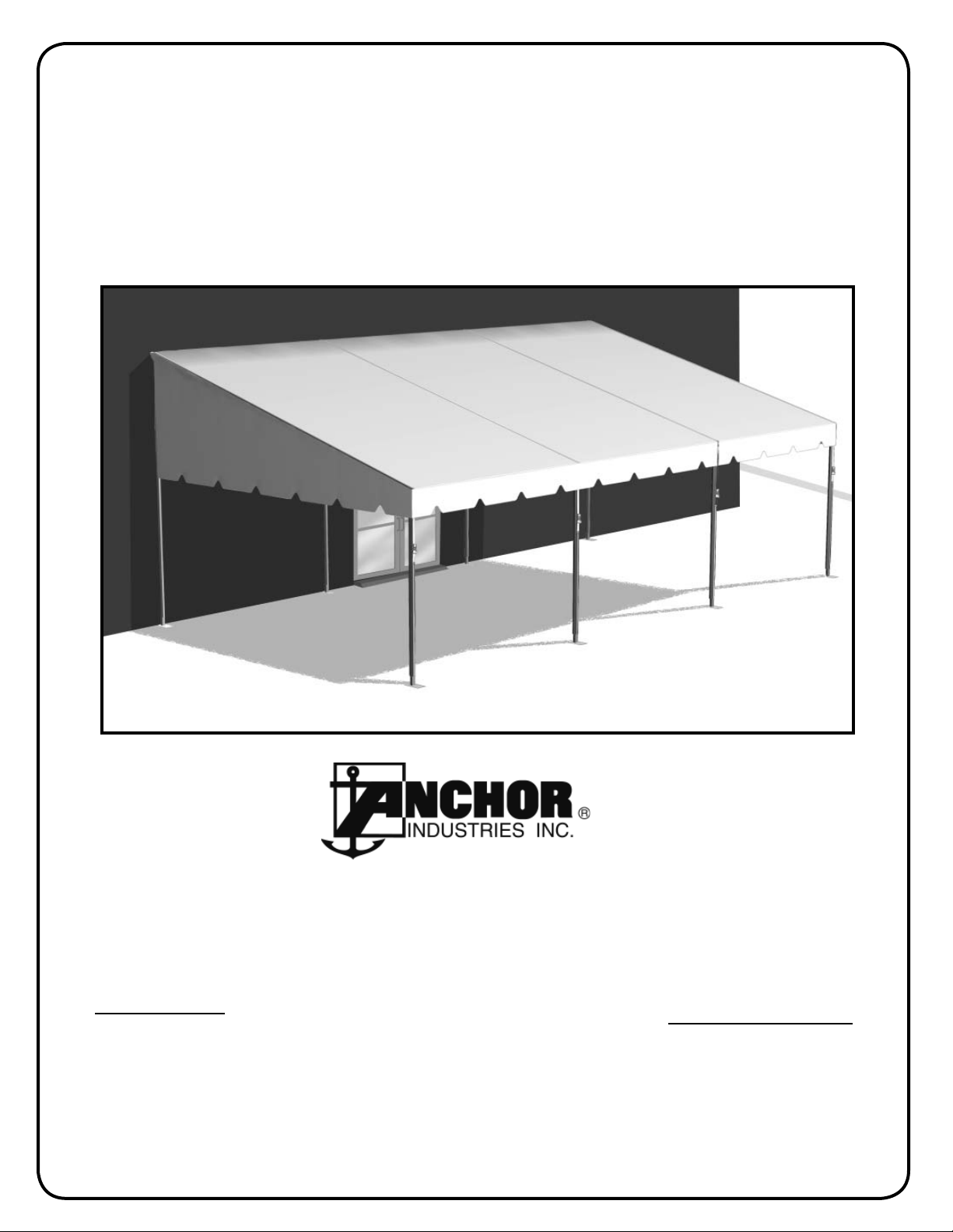
Assembly Instructions
Navi-Trac® LT/CS Pavilion
12’ to 24’ Projection
EVANSVILLE, INDIANA
Please read all assembly / installation instructions before the installation or removal of this product.
PHONE: 812-867-2421
SALES OFFICES:
1100 BURCH DRIVE
PO BOX 3477
EVANSVILLE, IN 47733 USA
Quality, Craftsmanship and Service since 1892
EC 3597
FAX: 812-867-0547
1-800-544-4445
EMAIL: tents@anchorinc.com
www.anchorinc.com
PRODUCTION FACILITY:
EVANSVILLE, IN
NTLTPAV 0211
Page 2

NAVI-TRAC LT PAVILION INSTALLATION SAFETY
GUIDELINES
Your own installation techniques will evolve to fit the varied needs of your clients, the experience level of your installation
crews, the nature of other tentage that may be common to the installation site being planned, and the equipment that you
may have available or with which you feel most comfortable. Whatever techniques you adapt for your crews, we encourage you to keep safety utmost in mind.
Please read through this assembly manual completely before beginning your installation. Be sure the proper equipment,
crew and safety precautions are in place. We hope that you enjoy the design features of the Navi-Trac Lite™ Pavilion
each time the unit is installed.
1. It is recommended that workers wear safety shoes and hard-hats on site.
2. When moving frame sections by hand, use proper lifting techniques to protect the back, and avoid pinching
fingers while making hardware connections.
3. Be sure all workers are cautious and attentive to the falling paths of frame sections being raised or
lowered.
4. Be aware to avoid contact of frame sections with any overhead power lines near the site.
5. When anchoring the structure, avoid all underground power lines and gas lines or other utility easements.
6. Keep site clear of debris to avoid tripping, especially while carrying frame parts or bundles of fabric.
7. Do not drag bundles of fabric on concrete, asphalt, or ground as this can cause damage to the fabric from
abrasion through the bag.
8. Do not climb onto the fabric “roof” of the structure. When necessary, work safely from a ladder of
appropriate size.
9. When standing frame sections to vertical, or when lowering, use a smooth motion and have other
workers “foot” the base of the section to avoid slippage along the ground.
10. When installing gabled end units, be sure all beams are stabilized either by safety guys or cross cabling until connected to a section of the unit that is already stabilized in this manner.
11. When installing a unit in which the overall length exceeds 60 ft, add one extra X-cabled bay for each addi-
tional 60 ft of length. To meet design loads, no more than 60 ft of consecutive length can remain non-X-
cabled.
12. The installation method described here requires coordination of tasks between workers. A safe installation is
dependent on that coordination. Please work cooperatively as a team.
2
Page 3

Parts List
NAVI-TRAC LT/CS PAVILION INV 10X20 10X10 12X20 12X10 14X20 14X10 16X20 16X10 18X20 18X10 20X20 20X10 22X20 22X10 24X20 24X10
COMPONENT DESCRIPTION # MID MID MID MID MID MID MID MID
ALUMINUM EXTRUSION
ANODIZED W/5 CHANNEL OPENINGS
EAVE-10'-0" 8004400 2121212121212121
REAR EAVE-10'-0" 8004475 2121212121212121
EAVE-10' PROJECTION 80932C 3 1
EAVE-12' PROJECTION 80760 3 1
EAVE-14' PROJECTION 80789 3 1
EAVE-16' PROJECTION 80761 3 1
EAVE-18' PROJECTION 80762 31
EAVE-20' PROJECTION 80763 31
EAVE-22' PROJECTION 80764 31
EAVE-24' PROJECTION 80765 31
EAVE SPLICE-24' PROJECTION 80766 31
RAFTER -10' PROJECTION 80931C 3 1
RAFTER -12' PROJECTION 80751 3 1
RAFTER-14' PROJECTION 80752 3 1
RAFTER-16' PROJECTION 80753 3 1
RAFTER-18' PROJECTION 80754 31
RAFTER-20' PROJECTION 80755 31
RAFTER-22' PROJECTION 80756 31
RAFTER-24' PROJECTION 80757 31
RAFTER SPLICE-22' PROJECTION 80758 31
RAFTER SPLICE-24' PROJECTION 80759 31
UPRIGHTS:
UPRIGHT - 8'-0" 80044506262626262628282
UPRIGHT - 9'-0" 8004480
UPRIGHT - 10'-0" 8004455
UPRIGHT REAR SPLICE-10' PROJECTION 80934C 3 1
UPRIGHT REAR SPLICE-12' PROJECTION 80768 3 1
UPRIGHT REAR SPLICE-14' PROJECTION 80769 3 1
UPRIGHT REAR SPLICE-16' PROJECTION 80770 3 1
UPRIGHT REAR SPLICE-18' PROJECTION 80771 31
UPRIGHT REAR SPLICE-20' PROJECTION 80772 31
UPRIGHT REAR SPLICE-22' PROJECTION 80773 31
UPRIGHT REAR SPLICE-24' PROJECTION
MISC. COMPONENTS:
RIDGE 10'-0" 80767 2121212121212121
RAFTER BRACE 3580666 313131
10'-0" PURLIN (NAVI-TRAC) 80410 2 121212121
MID TENSIONING TUBE 807792121212121212121
MID TENSIONING TUBE SPLICE 80780 1111111111111111
CONTAINER #1:
BASE PLATE ADJUSTABLE-4 HOLE 80775 6262626262626262
BASE PLATE ADJUSTABLE-2 HOLE 8004505 22
RIDGE WELDMENT ASSEMBLY 80750 3131313131313131
15.5 DEGREE EAVE WELDMENT 80790 1111111111111111
15.5 DEGREE EAVE END RIGHT WELDMENT 80777 11111111
15.5 DEGREE EAVE END LEFT WELDMENT 80778 11111111
END UPRIGHT EAVE WELDMENT 3582180 22
FRAME ATTACHING BRACKET ASSEMBLY 80781 3131313131313131
NAVI-TRAC LT/CS PAVILION INV 10X20 10X10 12X20 12X10 14X20 14X10 16X20 16X10 18X20 18X10 20X20 20X10 22X20 22X10 24X20 24X10
COMPONENT DESCRIPTION # MID MID MID MID MID MID MID MID
CONTAINER #2: #1417C #1418C #1403 #1404 #1405 #1406 #1407 #1408 #1409 #1410 #1411 #1412 #1413 #1414 #1415 #1416
RAFTER "X" CABLE ASSY-10' PROJECTION 80936C 4
RAFTER "X" CABLE ASSY-12' PROJECTION 80782 4
RAFTER "X" CABLE ASSY-14' PROJECTION 80783 4
RAFTER "X" CABLE ASSY-16' PROJECTION 80784 8
RAFTER "X" CABLE ASSY-18' PROJECTION 80785 8
RAFTER "X" CABLE ASSY-20' PROJECTION 80786 8
RAFTER "X" CABLE ASSY-22' PROJECTION 80787 8
RAFTER "X" CABLE ASSY-24' PROJECTION 80788 8
CONTAINER #3:
1/2-13 x 3 1/4" Shoulder Eye Bolt (Navi-Trac) 3020525 22244444
TENSION LOCK PIN 3102865 6262626262124184184
1/2-13 x 2 3/4" H.H.C.S. GRD.5 ZC. 3023425 3162
1/2-13 HEX JAM NUT ZC.W/ NYLON INSERT 3024630 3162
OPTIONAL:
STAKES FOR BASE PLATES - 1"x30" DBL. HEAD
STEEL STAKE
80774 31
37042306262626262628282
#1409 #1410 #1412#1404 #1405 #1407 #1408#1403 #1406#1417C #1418C #1416#1411 #1414 #1415#1413
3
Page 4
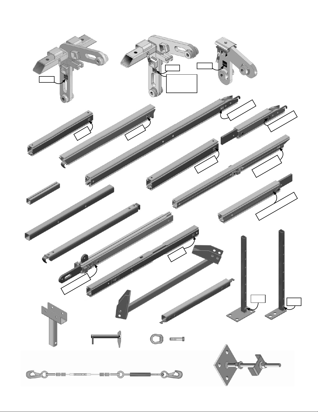
PARTS ILLUSTRATIONS
EWP
EAVE WELDMENT
EAVE
REAR EAVE - DROP IN
TENSIONING
TUBE SPLICE
E - 10
EAVE END R/L
WELDMENT
(RIGHT SHOWN)
EE - 10
EAVE/PROJECTION (NUMBER DENOTES
PROJECTION SIZE)
EPR
EPL - LEFT
(OPPOSITE
SHOWN)
EAVE 24’ PROJECTION
RWP
EP-24
RAFTER
RIDGE WELDMENT
EP - SIZE
RP- 24
24’ EAVE SPLICE
RP - SIZE
RS-22 or RS-24
TENSIONING TUBE
UR-SIZE
END UPRIGHT EAVE
WELDMENT
PURLIN
UPRIGHT REAR UPPER SPLICE
UPRIGHT 8’
TENSION LOCK
PIN
EYE NUT AND BOLT
U-8
RAFTER BRACE
RIDGE
RAFTER SPLICE PROJECTION
BAP
BASE PLATE
ADJUSTABLE
4-HOLE
BASE PLATE
ADJUSTABLE
2-HOLE
BA
RAFTER “X” CABLE
PARTS SHOWN ARE NOT TO SCALE.
4
FRAME A TT ACHING BRACKET
Page 5
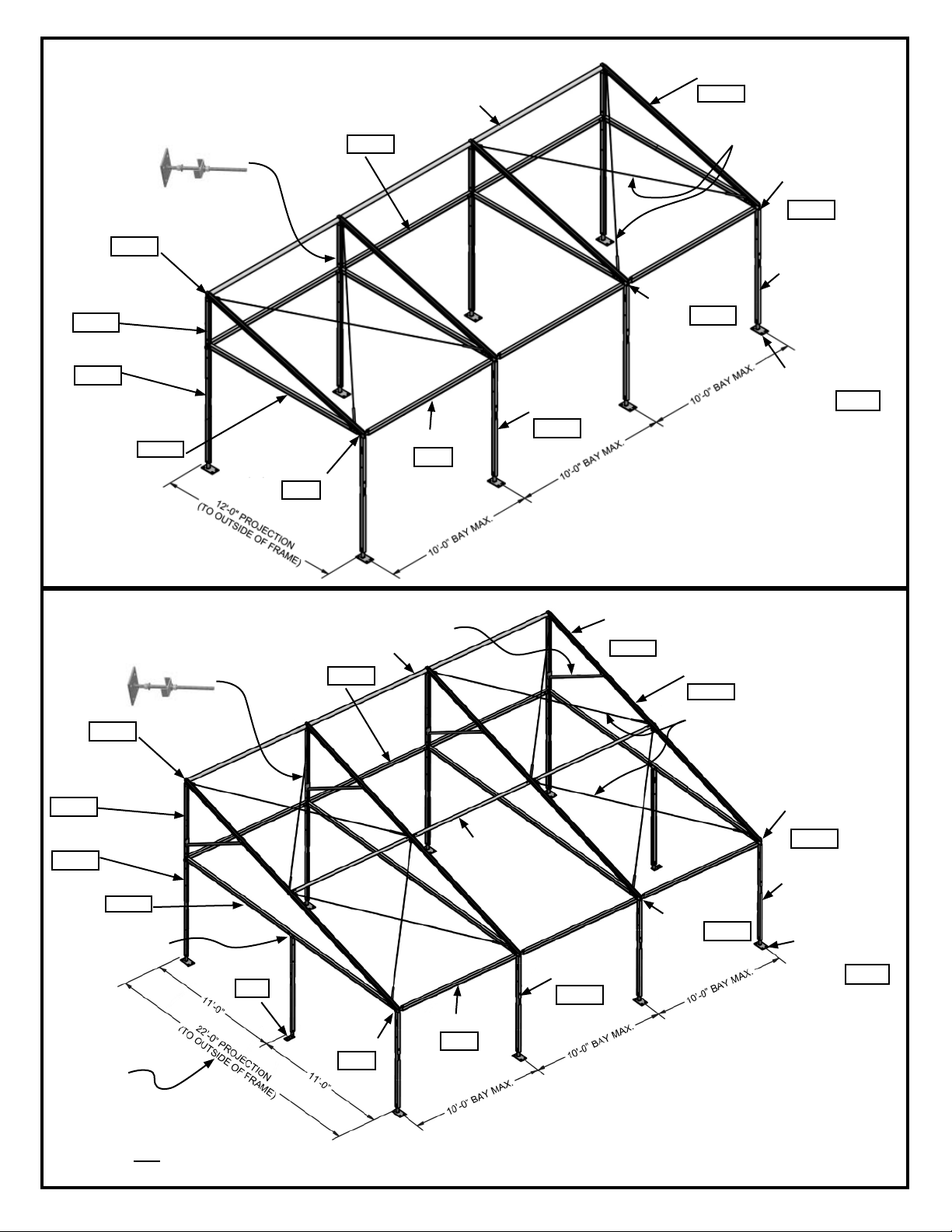
(1) FRAME ATTACHING
BRACKET ASSY SUPPLIED FOR EACH UPRIGHT
REAR UPPER SPLICE FOR
ATTACHMENT TO EXIST.
BUILDING.
RIDGE
WELDMENT
ASSY
RWP
UPRIGHT REAR
UPPER SPLICE
UR-12
ASSEMBLED FRAME ILLUSTRATIONS
RIDGE
REAR EAVE,
DROP-IN
EE-10
EAVE WELDMENT
RAFTER - 12’ PROJECTION
RP-12
RAFTER “X” CABLES
END LEFT
WELDMENT
EPL
NOTE: UPRIGHTS
ARE 8’ TO 10’ ADJUSTABLE HEIGHT.
EWP
UPRIGHT-8’
U-8
EAVE PROJECTION 22’
NOTE: STAKES ARE OPTIONAL, NOT SUPPLIED WITH
STANDARD UNIT.
(1) FRAME ATTACHING
BRACKET ASSY SUPPLIED FOR EACH UPRIGHT
REAR UPPER SPLICE FOR
ATTACHMENT TO EXIST.
BUILDING.
RIDGE
WELDMENT
ASSY
UPRIGHT REAR
UPPER SPLICE
EP-12
RWP
UR-22
UPRIGHT-8’
U-8
EAVE PROJECTION 22’
EP-22
END UPRIGHT
EAVE WELDMENT
BASE PLATE
ADJ. 2-HOLE
EAVE END
RIGHT WELD.
EPR
REAR EAVE,
DROP-IN
BA
EAVE - SLIDE
IN
E10
RAFTER BRACE ONLY
ON 20’ OR MORE PROJECTION FRAMES.
RIDGE
EE-10
PURLIN
UPRIGHT-8’
U-8
12’ PROJECTION SHOWN
UPRIGHT-8’
U-8
Most parts have labels affi xed
as noted in the outlined boxes.
Numbers refer to length.
RS-22
RAFTER SPLICE - 22’
PROJECTION
RS-22
RAFTER - 22’ PROJECTION
RP-22
RAFTER “X” CABLES
EAVE WELDMENT
EWP
BASE PLATE
ADJUSTABLE 4-HOLE
END LEFT
WELDMENT
BAP
EPL
NOTE: UPRIGHTS
ARE 8’ TO 10’ ADJUSTABLE HEIGHT.
BASE PLATE
ADJUSTABLE 4-HOLE
BAP
NOTE: UPRIGHT
CENTERED ON END,
REQUIRED ABOVE 20’
PROJECTION.
NOTE: 24’ PROJ. HAS EAVE
PROJECTION AND EAVE
SPLICE PROJECTION
EAVE END
RIGHT WELD.
EPR
EAVE - SLIDE
IN
E10
NOTE: STAKES ARE OPTIONAL, NOT SUPPLIED WITH
STANDARD UNIT.
Most parts have labels affi xed
as noted in the outlined boxes.
Numbers refer to length.
22’ PROJECTION SHOWN
5
Page 6

Point B
PLAN VIEW OF 3 BAY STRUCTURE
(22’ Projection shown)
BACK OF PAVILION
Point C
11’-1 7/8” for 22’ Projection
12’-1 7/8” for 24’ Projection
“A” DIMENSION - SEE TABLE
PLATE TO OUTSIDE OF BASEPLATE.
MEASURED FROM OUTSIDE OF BASE-
11’-5 1/16” for 22’ Projection
Point A
C
L
12’-5 1/16” for 24’ Projection
Front and Back
Uprights
10’-0” 10’-0” 10’-0”
C
L
Uprights
“B” DIMENSION - SEE TABLE
DIAGONAL IS MEASURED TO CENTER
BACK AND CENTER FRONT OF BASE-
PLATES AS SHOWN IN DETAILS.
C
L
FRONT OF PAVILION
30’-0”
Uprights
4-Hole base plate
(typ.)
Upright centered on
end required only
on structures above
20’ projection.
(2) Hole Base Plate
required at this
position only.
C
Front and Back
L
Uprights
Point D
LAYOUT DIMENSIONS
Pavilion Size “A” Dimension “B” Diagonal Dim.
12’ Projection x 30’ 12’-6 15/16” 32’-6 3/8”
14’ Projection x 30’ 14’-6 15/16” 33’-4 1/4”
16’ Projection x 30’ 16’-6 15/16” 34’-3 5/16”
18’ Projection x 30’ 18’-6 15/16” 35’-3 7/16”
20’ Projection x 30’ 20’-6 15/16” 36’-4 9/16”
22’ Projection x 30’ 22’-6 15/16” 37’-6 9/16”
24’ Projection x 30’ 24’-6 15/16” 38’-9 3/8”
To fi nd a diagonal measurement not listed here, use
this formula: width² + length² = diagonal²
Directions for Squaring the Tent
(see the diagram above)
1. Locate the four primary corners.
a. Using a tape measure, mark Points A & B (the width of the pavilion fi rst.
b. Using one tape measure, start from point B and measure the
length of the tent.
c. Using a second tape measure, start from point A and measure the
diagonal.
d. Mark the point at which these two tapes intersect. (Point C) This
will square the tent.
e. Using the same process, mark point D.
2. Locate points for intermediate uprights.
a. Using a tape measure running from points A
to B, mark for end uprights
(only on frames over 20’
projection).
b. Using a tape measure
running from points B to
C (or A to D) mark for side
uprights according to your
particular pavilion.
These markings will be
your guideline for tent
layout.
Standard 4-hole Base Plate
6
2-Hole Base Plate for End Uprights
Page 7

Step 1 - Parts Layout
•
Follow the directions on the previous page for squaring and marking
for the frame.
•
Lay out the parts neatly in their approximate location, as if the frame
were collapsed onto the ground.
(Figure 1a)
•
Upright
Rear
Upper
Splice
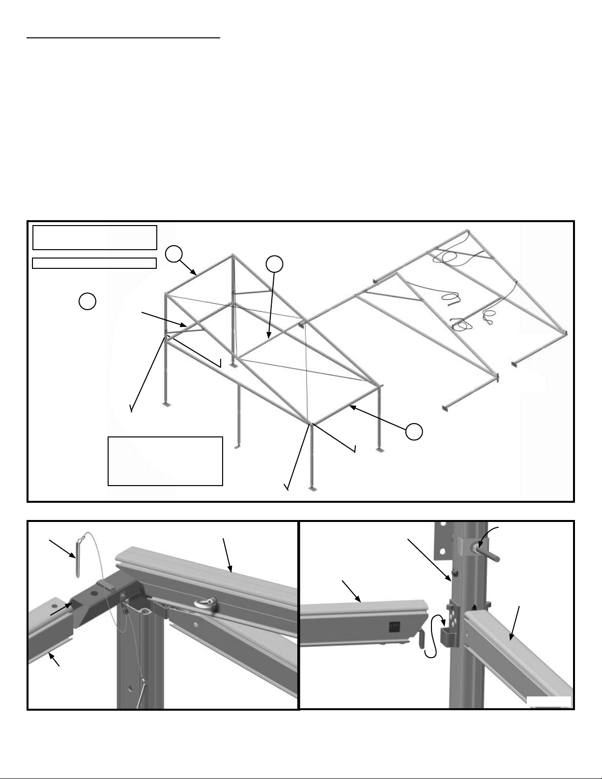
Step 2 - Beam Arch Assembly
Assemble the fi rst beam arch in the
•
following order:
Assemble upper triangle fi rst
1.
by fastening upright rear upper
splice to ridge weldment using
one of the pins attached to the
ridge weldment.
Drop hook end of Eave Projec-
2.
tion into Eave End Weldment
Bracket. (Figure 2a) Note: On
24’ projection, Eave projection
is spliced. Slide Eave Splice
Projection into 24’ Eave Projection and fasten using 1/2” bolt
and nut.
Drop slotted end of Eave
3.
Projection down over ear
located at bottom of upright
rear upper splice and pin
using a tension lock pin.
(Figure 2b)
Assemble Rafter Splice
4.
Projection to Rafter using
1/2” bolt and nut provided
(required only on frames
over 20’ projection)
Slide Rafter up onto ridge
5.
weldment and affi x using method detailed as follows:
On rafters with “X” cables in one of the adjacent bays such as end
•
bays (see illustration on page 5) connection must be made using the
eye nuts and bolts shipped with the “X” cables. Eye nut must face in
the direction of the “X” cabled bay because it is used for connection of
the “X” cables. (See Step 3)
In the case where there are two “X” cabled bay adjacent to one
•
another, the connection must be made using an eye bolt with eye nut.
(not usual)
On rafters with no “X” cables attach the rafter using the pin attached to
•
the ridge weldment.
6. On frames with 20’ projection or more, rafter brace is now attached to triangle.
Rafter Brace will only fi t one way- so if you are having trouble with alignment,
turn the brace around so that the opposite ends are now at the rafter and upright rear upper splice. (See Figure 2c)
7. Assemble uprights by sliding adjustable base plates into uprights and bolting
with bolts provided. See Figure 2d for assistance in assembling the upright in
the correct position.
8. On Rear upright, slide Upright rear upper splice down into bottom upright and
pin with a tension lock pin. See Figure 2d for assistance in assembling the
upright in the correct position.
9. Assemble all Beam arches with baseplates in correct position for raising.
Upright
Eave End Weldment
Ridge
Weldment
Rafter Splice
Projection
Rafter Brace (only
on frames 20’ projection and larger.
End Upright
Eave Weldment
Upright (only on
frames over 20’
projection.)
Base Plate
Adjustable
4-Hole
Note: End Upright used only on
frames larger that 20’ projection.
Eave projection
Figure 2a
22’ Projection Frame Shown
Rafter
Eave Projection
Base Plate
Adjustable
2-Hole
Upright Rear Upper
Splice Ear
Upright Rear
Upper Splice
Rafter Brace
Cross-sectional view of
Navi-Trac Lite Beam
Channeled
side of upright.
toward inside
of frame.
Eave End
Weldment
Upright
Base Plate
Adjustable
4-Hole
Figure 1
Slot
Eave projection
Figure 2b
Rafter
Tension
Lock Pin
Figure 2c
Flat side of
upright. toward
outside of frame.
Figure 2d
7
Page 8

Step 3 - Raising the Beam Arches
Raise fi rst beam. Tie off securely or hold up using adequate installation personnel. Note: There are no stakes or guys
•
included with this frame, however, the installation kit (sold separately) includes eye bolt and eye nut for attaching to frame
along with safety webs that may be used to stake or tie-off frame to stabilize the fi rst beam while frame is being assem-
bled. See Figure 3a.
Raise the second beam arch, keeping base plate in place by using installation personnel or stakes (not included).
•
Note: Before Raising Beam Arches, all eye nuts and “X” Cables must be in place as
shown in Figure 3a. Turnbuckles should be open all the way.
22’ Projection Frame Shown
Frame sizes under 16’
projection have only (2)
cables per bay and no
purlins.
Eyenuts on
inside of Rafter
First beam arch assembled and raised.
1/2” x 3 1/4” cap screw
and eye nut may be used
with safety web guys from
installation kit for stabilizing
fi rst raised beam. (installation kit is an optional
purchase)
Note: If you are installing a 2-bay pavilion, both
bays must be “X” cabled, therefore, eye nuts and
eye bolts must be used at center beam arch (similar
to confi guration at right).
Eyenuts face
ground on second rafter.
Note: Turnbuckles
at free end.
Eyenut
Eyenuts on
inside of Rafter
Eyebolt and safety
webs from installation
kit may be temporarily
installed for stabilizing fi rst raised beam.
(Use eyebolt with
eyenut from standard
frame hardware.)
Figure 3a
8
Page 9

Before placing frame in fi nal position, attach
frame attaching bracket to upright rear upper
splice on each rear upright.
Remove stablizer plate, washer and hex nut from rod
•
on bracket.
Insert rod into upright rear upper splice from back of
•
pavilion.
Place stabilizer plate, washer and hex nut back onto
•
rod so that bracket stays in place. Do not tighten until
frame and fabric are completely assembled and installed. Do not use stabilizer plate at corner uprights.
Plate for connection to
existing structure.
Stablizer plate, washer
and hex nut
Stablizer plate may not
be used at corner uprights. Remove.
Figure 3b
U-Shaped stabilizer may not
be used at corner uprights
due to fabric interference.
Figure 3c
9
Page 10
Step 4 - Joining Beam Arches
Join in the order listed: (Figure 4a)
•
Front Eave - slide one end of front eave tube onto end eave weldment with bottom channel down. Align holes and pin
with one of the pins attached to the weldment. Figure 4b.
•
Gable End Mid Eave - drop gable end mid eave into brackets on upright rear upper splices. Figure 4c
•
Ridge - fi t ridge into slots provided in ridge weldment. Figure 4d.
•
Purlin - Drop curved end of purlin into rafter bracket. See fi gures 4e and 4f. Drop square hook end into the correspond-
ing rafter bracket.
•
Note: If optional installation kit has been used, remove eyenut at lower end of fi rst rafter and replace with nut
before snapping cables in place.
Note: If Installation Kit has been purchased, the short lifting bar may be used to lift bars into place.
Snap lower ends of cables onto their respective eye nuts. Square up frame by tightening turnbuckles
•
Parts labeled numerically in
the order to be installed.
22’ Projection Frame Shown
Gable End
3
Mid Eave
2
Ridge
4
Purlin
Longer
Pin
Front Eave
Frame sizes under 16’
projection have only (2)
cables per bay and no
purlins.
Rafter
Figure 4b
Upright Rear
Upper Splice
Gable End Mid
Eave
1
Front Eave
Figure 4a
Frame attaching
bracket.
Eave Projection
Figure 4c
10
Page 11

Ridge
Weldment
Curved hook end Square hook end
Purlin
Ridge
Rafter
Figure 4d
Figure 4e
Rafter
Purlin
Figure 4f
Step 4 - Cont’d
Continue raising beams and attaching them until frame is completely assembled. Connect all cables and tighten. Measure to
be sure frame is square and in proper position.
Step 5 - Fabric Mid Installation
With one installer at top of each rafter, feed eave end of kedar into top channel opening of ridge weldment and down into
•
rafter. (Figure 5a) Feed both kedars at the same time and at the same rate until the ends of the kedars are at end of rafter at eave. Optional method: Snap pull ropes onto pull rings at mid eaves and pull mids down from top after kedars are
started into channels simultaneously.
Raise back ends of mid kedars up until bottom of kedar can be fed down into top of channel on Upright Rear Upper
•
Splice. Feed both kedars down at the same time and at the same time until kedars are fully inserted into channels. (Figure 5b)
Continue this process until all mids are installed.
•
Mid
Pull Ring at
Mid Eave
~
Ridge Weldment
Eave end of kedar
Front curtain
folded back onto
top of mid
Rafter
Ridge of adjacent bay
Upright Rear
Upper Splice
Rafter
Mid
Kedar feeding down into
channel
Figure 5a
Figure 5b
11
Page 12

Step 6 - Fabric
Ends Installation
End Fabric
With one installer at
•
top of the end rafter,
feed eave end of
kedar into top channel opening of ridge
weldment and down
into rafter until end
of kedar reaches
the end of the rafter.
(Figure 6a)
Raise bottom end of
•
back kedar up until
bottom of kedar can
be fed down into
top of channel on
Upright Rear Upper
Splice. (Figure 6b)
After end fabric is in
•
place, fi esta buckles
on inside of fabric at
eave must be connected. Slide kedar pieces with d-ring into top/outside
channel of eave beam. Align these with corresponding
fi esta buckles. Slide web through d-ring as shown in
fi gure 6c. Tighten webs.
End Fabric is installed.
•
Rafter
Figure 6a
Rafter
Bottom end of
back kedar
Kedar
feeding
down into
channel
End Fabric
Figure 6b
Fiesta Buckle attached to inside of
end fabric. (Fabric
not shown.
12
Kedar piece
with D-ring
Figure 6c
Page 13

Step 7 - Fabric Tensioning
At back of pavilion, snap buckles of back-end straps to corresponding buckles at bottom of mids. Insert bottom hook into
•
slot at back of upright. Tighten just enough so that hook does not fall out of slot. (Figure 7a)
At front of mids, insert tension tubes into pockets under curtain. Between mids, use a tension tube splice to connect
•
tubes. (Figure 7b) Before insertion, hang tension strap with ratchet and hook over the tension tube splice. At ends, hang
tension strap over end of tension tube as shown in Figure 7c.
Insert hook of tension strap into slot in front upright. Crank ratchet until tension strap stays in place but do not tension.
•
Check mids to be sure they are all pulled to the same point in front and back. Check back end straps to be sure they are
tightened uniformly. When you have checked these things, you may now ratchet the front tension straps. Tighten until all
mids are uniformly snug.
Rear Corner Upright
Frame attaching
bracket
Use single back
end strap at corner
upright.
Connect male buckle to female buckle
at bottom of mid.
Rear Upright
Mid Fabric
Frame attaching
bracket
Mid Fabric
Use double back
end strap at
uprights between
mids.
Slot in upright
Slot in upright
TENSIONING
TUBE SPLICE
Tensioning Tube Splice
TENSIONING TUBE
is used between mids
fi ts into ends of tension
tubes.
Back View
Figure 7b
Tension Pocket with
tension tube inserted.
Tension strap over end
of tension tube at front
corner.
Inside view looking at tension
pocket under curtain.
Figure 7a
Figure 7c
13
Page 14

Step 8 - Fastening Frame to Existing Building
At back of pavilion, adjust the frame attaching bracket so that is is fi tted up to existing building.
•
Customer must determine and install the type of device that is best suited to attach frame to existing building.
•
U-Shaped stabilizer may not be
used at corner uprights due to
Connection to existing building
must be determined by customer.
fabric interference.
Frame Attaching Bracket
14
Page 15

Notes:
15
Page 16

EVANSVILLE, INDIANA
PHONE NUMBER
812· 867· 2421
FAX NUMBER
812· 867· 0547
Anchor products are of superior design and operate best within the parameters of these instructions. It is imperative
that the instructions be carefully read and COMPLETELY FOLLOWED. Please read installation instructions before the
installation or removal of this product. Installation instructions are available online at www.anchorinc.com or by calling
1-800-544-4445.
CAUTION:
1. For each installation, the installer is solely responsible for evaluating the site and the proper securing method
determined. Some soils require different staking or securing than that provided with the tent. Due to this variety of
soil conditions, these are the manufacturer’s suggested sequence of installation procedures. Anchor’s responsibility
is limited to the manufacture of the tent parts and materials. We are not responsible for methods that installers may
choose to erect and secure the tent to the ground.
2. The number of stakes suggested in the installation instructions do not necessarily meet all or any relevant codes
on the site of the tent installation. The number of stakes suggested will, in many cases, keep the tent erected,
however, due to various soil conditions; these stakes will be insuf¿ cient to keep the tent secure in high winds.
It is the tent installer’s responsibility, not the manufacturer, to determine the appropriate number of stakes to meet
the necessary wind loads on the site. Regardless of the number of stakes we suggest, we make no representation
or warranty as to whether this speci¿ c number of stakes will meet the local tent code. Anchor does not, nor can
it make any suggestions, representation, or warranties about the adequate staking required at each speci¿ c
installation site. Staking information provided in the installation instructions is not a suggestion about what is
necessary to meet a site-speci¿ c load.
For additional important information, consult: “The IFAI Procedural Handbook For the Safe Installation and
Maintenance of Tentage” and the IFAI Pocket Guide “Pullout Capacity of Tent Stakes”, both available from
the IFAI Tent Rental Division or on our website.
3. Inasmuch as the weather is unpredictable, good judgment and common sense must be incorporated within
installation guidelines. It is the responsibility of the tent installer/maintainer to determine the severity of the weather,
proper time and method of installation and/or erection and disassembly. Note: We recommend that snow and
ice be removed from the tent surface as soon as possible because accumulation will damage the tent
or fabric structure. Please consult with our Engineering Department about the maximum loads for each
product.
This product has been manufactured for use as a temporary structure. For the safety of all occupants, evacuation
is recommended if threatening weather occurs, or if there is any doubt concerning the safe use of this product.
4. Proper safety equipment should be used at all times to insure a safe installation and take down. We suggest a
careful evaluation be made to determine safety equipment needed, such as hard hats, steel-toe shoes, safety
glasses and other as required. It is our desire that all installations are safe. Please be aware of hidden dangers
both underground, i.e., gas lines, water lines, electrical lines, etc. and above the tent such as power lines and
telephone lines.
5. Anchor stands behind its products in accordance with its standard Terms and Conditions of sale. A copy of our
Terms and Conditions of Sale can be obtained by contacting Anchor at the telephone number and/or address on
this document.
28.2 03-04-09
 Loading...