

Page 1
Assembly Instructions
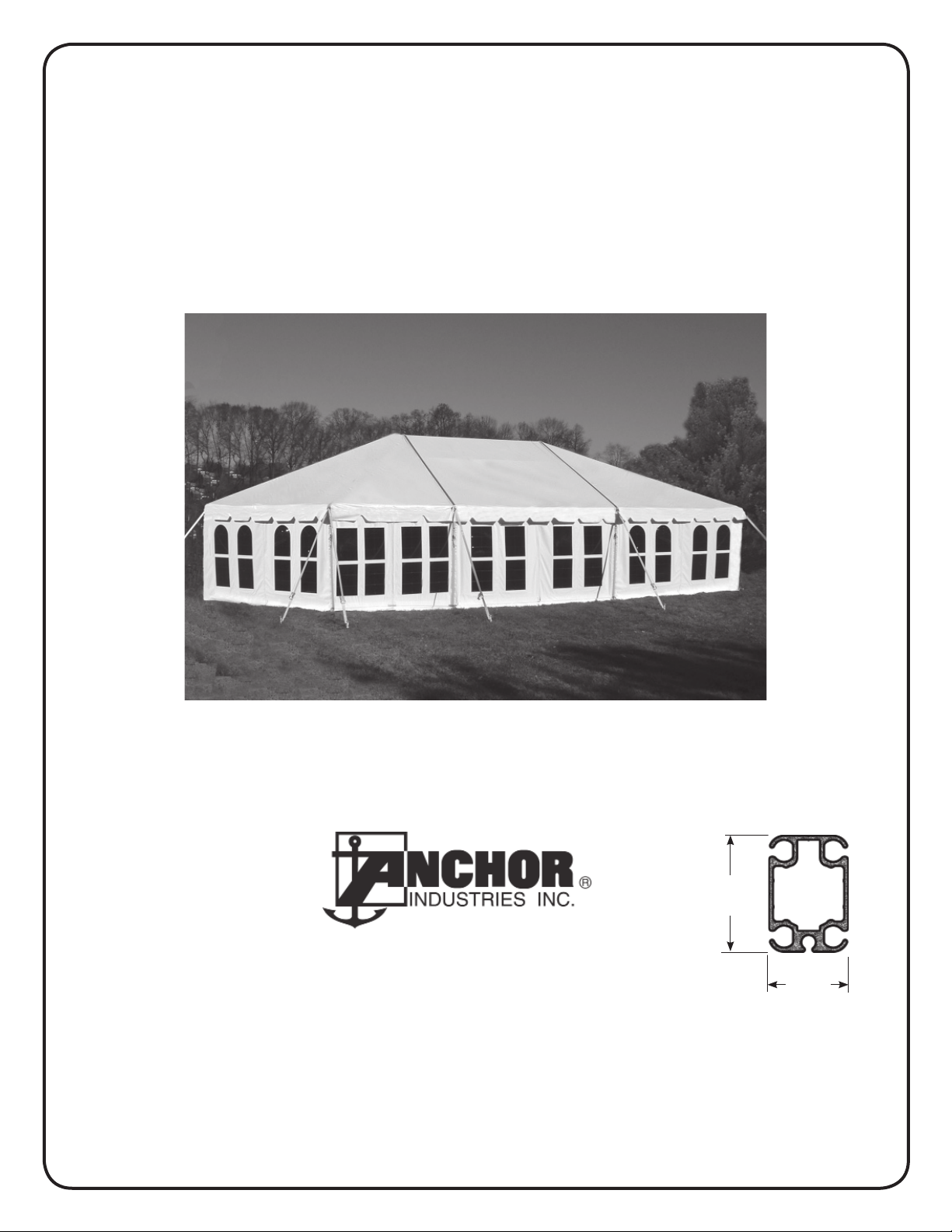
Navi-Trac Lite® Frame Tent
20’ Wide System
Please read all assembly / installation instructions before the installation or removal of this product.
WEB
EC4714
EVANSVILLE, INDIANA
1100 Burch Dr., Evansville, IN 47725
Ph. 812-867-2421 • Fax. 812-867-0547
E-mail: tents@anchorinc.com • www.anchorinc.com
3.4”
(REF.)
2.3”
(REF.)
Navi-Trac Lite
Beam
NTLT20 1213
R 6/2/14
Page 2

Table of Contents
Preparation
Introduction to
Component Illustrations................................................................................ 4
Frame Terminology....................................................................................... 5
Safety Guidelines.......................................................................................... 6
Web Guy and Staking Guidelines..................................................................7
Frame Assembly
Cross Beam.................................................................................................. 8
Hip End Upper Frame.................................................................................. 9
Upright Installation & Adding Mid Bays........................................................10
Hip Frame Completion................................................................................. 11
Fabric Installation
Fabric Guide Bracket.................................................................................... 11
Navi-Trac LT, Gabled LT, and Clearspan (CS)......................... 3
Hip End Panel............................................................................................... 12
Mid Panel Installation.................................................................................... 13
Fabric Tensioning.......................................................................................... 14
Appendix #1
Gabled End Frames...................................................................................... 16
Gabled End Fabric Panels............................................................................ 17
2 Gabled Ends - Frame Safety..................................................................... 18
Appendix #2
Navi-Trac Lite Clearspan Units.................................................................... 19
2
Page 3
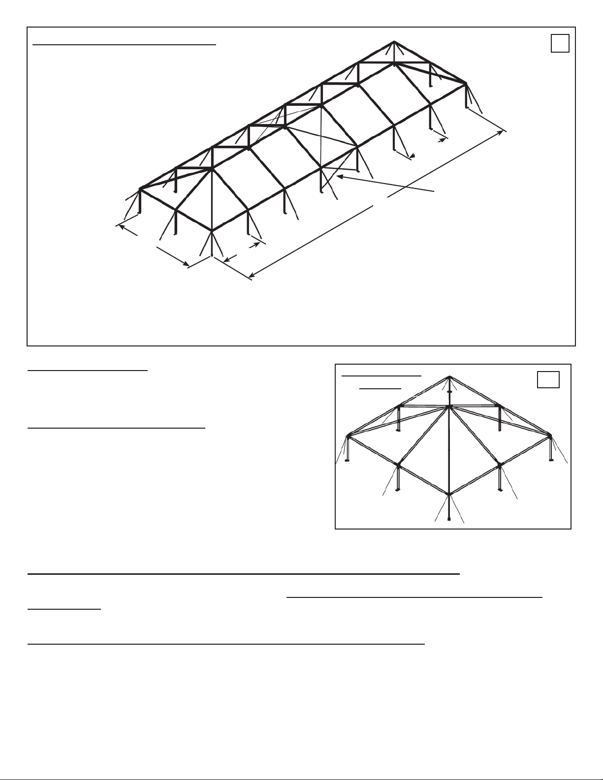
20’ NAVI-TRAC LT HIP END FRAME
1
15’
(MAX)
20’
10’
INTRODUCTION
The NAVI-TRAC LT can be configured as a Hip End, Gabled End,
or Clearspan unit, as described below:
20’ NAVI-TRAC LT HIP END UNITS
The 20’ wide NAVI-TRAC LT frame configuration is based on the
hip roofed square tent shown at right. Hip bars connect corners
to the peak, and rafters connect eave bars to the peak. The
square tent can be extended into a rectangle by adding 10’ or 15’
bays consisting of parallel beams connected to the hip ends and
to each other by ridge bars, purlins, and eave bars.
70’
SQUARE TENT
FRAME
When the overall length
of the unit exceeds 60 ft.,
an X-cabled bay must be
added for each additional
60’ of length.
2
20’ NAVI-TRAC LT GABLED END UNITS (AND HIP-GABLED & HEX-GABLED UNITS)
The 20’ LT can also be supplied and installed as a gabled end tent consisting of a series of parallel beams interconnected
by ridge bars, purlins and eave bars (see the Appendix I). The hip end, gabled end & hex end versions of the LT
are guyed units that depend on staked, ratcheted guy webs at legs and corners for their stability. All three versions are
supplied with uprights adjustable from 8 ft to 10 ft high, with the gabled end unit requiring at least one bay of X-cabling.
20’ NAVI-TRAC LT CLEARSPAN (CS) UNITS (Gabled End Configuration only)
By adding appropriate additional X-cabling, and hinged Base Plates, the 20’ NAVI-TRAC LT can be converted into the 20 ft
NAVI-TRAC CS, a clearspan unit which is installed without external guy webs (see Appendix 2).
3
Page 4
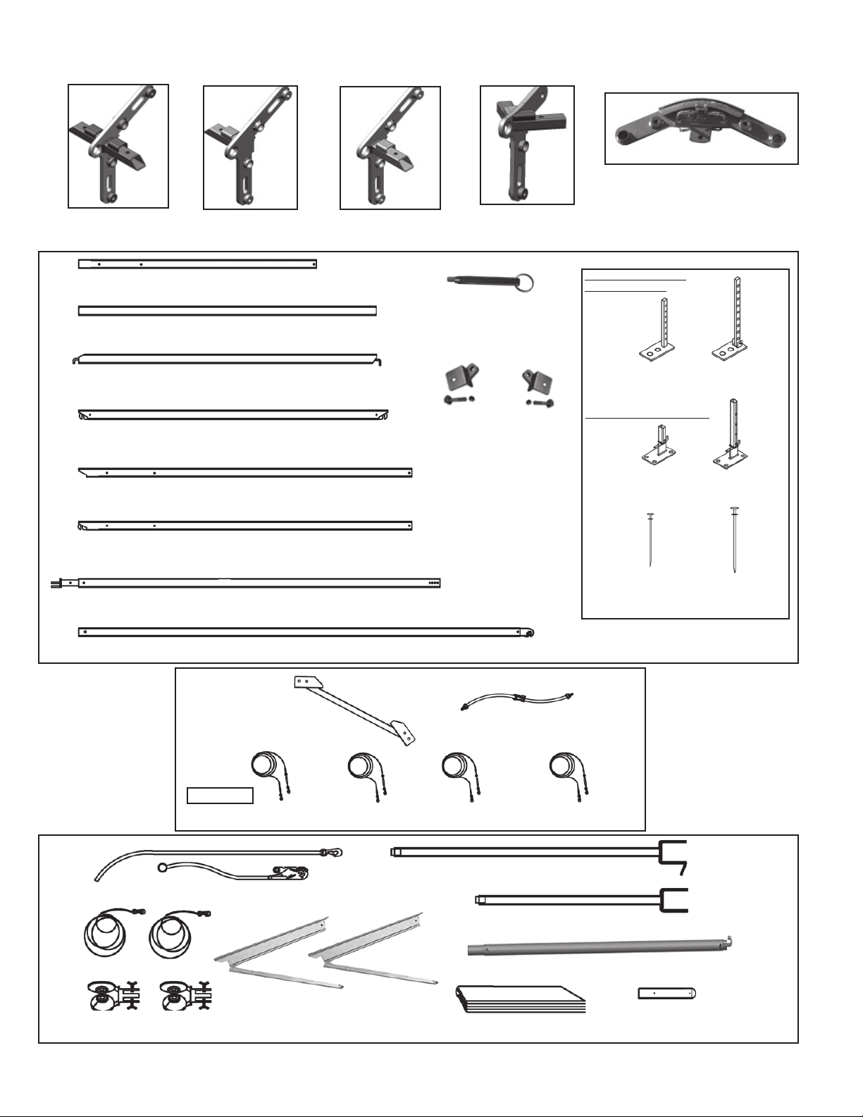
20’ NAVI-TRAC LT COMPONENT ILLUSTRATIONS
(SEE PART LISTS ON PG #11 AND APPENDICES 1 AND 2)
(NOTE: FOR GABLED ENDS, THE
EAVE WELDMENT
(EW)
GABLED END
WELDMENT “L” (GWL)
GABLED END
WELDMENT “R” (GWR)
CORNER WELDMENT
(CW)
BRACKET HARDWARE CAN BE
REMOVED FROM ONE SIDE, IF
RIDGE WELDMENT (RW)
DESIRED.)
UPRIGHT 8’ (U-8)
EAVE, 10’ (E-10)
GABLED END WING EAVE - 10’ (EW-10)
RIDGE, 10’ W/ HOOKS (RG-10) 9’-9 1 /2”
RAFTER, 20’ (R-20) 10’-6 1/2”
RAFTER, 20’ W/ HOOKS (RH-20) 10’-9”
GABLED END UPRIGHT W/ TOP FITTING (GU)
HIP, 20’ W/ HOOKS (H-20) 14’-2 1/2”
TENSION LOCK
PIN (TP)
GFL
GABLED END RAFTER
FITTINGS (LEFT &
RIGHT) W/ BOLT & NUT
GFR
2-HOLED PLATES for
HIP & GBL UNITS
BASEPLATE
ADJ
(BA)
4-HOLED PLATES FOR CS
BASEPLATE
HINGED
30”
STAKE
(1) REQ’D PER
BASE PLATE
BASEPLATE, GABLED
END, ADJ
BASEPLATE, GABLED
(BH)
END, HINGED
STAKE
(BAG)
(BHG)
42”
(1) REQ’D PER
GUY
X-CABLING
INSTALLATION SAFETY GUYS
FABRIC PULL ROPES
WHEELED PANEL GUIDES
KNEE BRACE (KB)
NAVLT-BAY10
NAVLTCS-BAY10-U8
WHEELED GUIDE BRACKETS
WEB RATCHET (WR)
NAVLTCS-BAY10-U9
NAVLTCS-BAY10-U10
LONG LIFTING BAR W/ CRADLE
SHORT LIFTING BAR W/ CRADLE
PUSH POLE ASSEMBLY
DROP CLOTH
FABRIC END FITTING
(FOR PUSH POLE)
4
Page 5
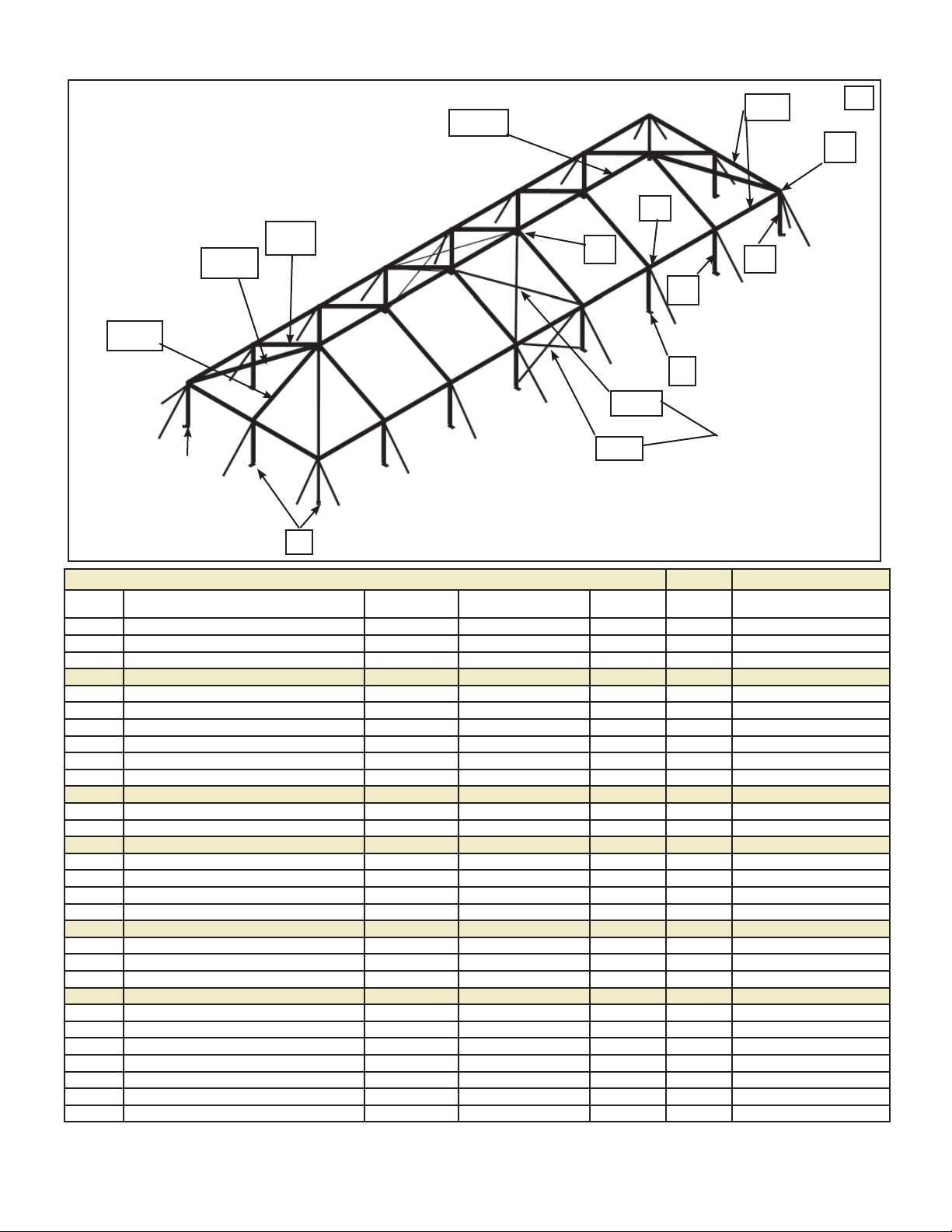
20’ NAVI-TRAC LT FRAME TERMINOLOGY
RH-20
H-20
R-20
BA
RG-10
RW
X8-10
EW
XR-10
U-8
BA
E-10
3
CW
U-8
REQUIRED ONLY ON
UNITS EXCEEDING
60 FT IN LENGTH.
Component Chart
LABEL PARTS FOR HIP END UNITS 20’ x 20’ 10’
(LETTER (For Gabled End, see Appendix 1) POSITION ID PART HIP EXTENSION
ON DWG) COMPONENT DESCRIPTION CODE CODE # END MID
TOP EXTRUSIONS WITH CHANNELS:
E-10 EAVE - 10’ 8004400 8 2
RG-10 RIDGE W/ HOOKS - 10’ 8004405 0 1
R-20 RAFTER 20’ 8004425 2 2
RH-20 RAFTER 20’ W/ HOOKS 8004430 2 0
H-20 HIP - 20’ W/ HOOKS 8004420 4 0
UPRIGHTS:
U-8 UPRIGHT - 8’ 8004450 8
WELDMENTS, FITTINGS & PLATES:
BA BASEPLATES, ADJUSTABLE, 2-HOLED 8004505 8 2
CW CORNER WELDMENTS W/ PINS 8004525 4 0
RW RIDGE WELDMENTS W/ PINS 8004545 1 1
EW EAVE WELDMENTS W/ PINS 8004530 4 2
X-CABLES:
X8-10 X-CABLE, 8’ UPRIGHT 10’ BAY GREEN NAVLTCS-BAY10-U8 8004550 0 4 (OVER 60’L ONLY)
XR-10 X-CABLE, RAFTER 10’ BAY BLUE NAVLT-BAY10 8004565 0 4 (OVER 60’L ONLY)
INSTALLATION TOOLS:
LONG LIFTING BAR W/ CRADLE 80702
SHORT LIFTING BAR W/ CRADLE 80701
FABRIC PULL ROPES 80730
WHEELED PANEL GUIDE/ ASSEMBLIES 80731
PUSH POLE ASSEMBLY 80707
FABRIC END FITTING FOR PUSH POLE 80732
DROP CLOTH (8’ x 30’) 80705
OTHER COMPONENT NOTES:
STAKES AND GUYS ARE NOT INCLUDED IN THIS TABLE. (1) 1” X 30” STAKE MUST BE USED FOR EACH BASE
PLATE. EACH GUY REQUIRES THE USE OF A 1 1/8” X 42” STAKE.
QTY QTY
5
Page 6

NAVI-TRAC LT INSTALLATION SAFETY GUIDELINES
Your own installation techniques will evolve to fit the varied needs of your clients, the experience level of your installation
crews, the nature of other tentage that may be common to the installation site being planned, and the equipment that you
may have previously available or with which you feel most comfortable. Whatever techniques you adapt for your crews, we
encourage you to keep safety utmost in mind.
Please read through this assembly manual completely before beginning your installation. Be sure the proper equipment,
crew and safety precautions are in place. We hope that you enjoy the design features of the Navi-Trac Lite®
each time the unit is installed.
1. It is recommended that workers wear safety shoes and hard-hats on site.
2. When moving frame sections by hand, use proper lifting techniques to protect the back, and avoid pinching
fingers while making hardware connections.
3. Be sure all workers are cautious and attentive to the falling paths of frame sections being raised or
lowered.
4. Be aware to avoid contact of frame sections with any overhead power lines near the site.
5. When anchoring the structure, avoid all underground power lines and gas lines or other utility easements.
6. Keep site clear of debris to avoid tripping, especially while carrying frame parts or bundles of fabric.
7. Do not drag bundles of fabric on concrete, asphalt, or ground as this can cause damage to the fabric from
abrasion through the bag.
8. Do not climb onto the fabric “roof” of the structure. When necessary, work safely from a ladder of
appropriate size.
9. When standing frame sections to vertical, or when lowering, use a smooth motion and have other
workers “foot” the base of the section to avoid slippage along the ground.
10. When installing gabled end units, be sure all beams are stabilized either by safety guys or cross cabling until connected to a section of the unit that is already stabilized in this manner.
11. Pay close attention to the proper use of the Navi-Trac Frame Jack (see Page 9). Use care in position
the jack carefully to maintain proper balance points in relation to weight, wind, and terrain.
12. Before installing fabric, be sure the frame is safely guyed off against the windload the fabric will transfer to the
frame (in the LT and Gabled LT). In the Clearspan (CS) units, be sure X-cabling is in place.
13. When liner ropes are installed on the frame during installation, leave these ropes partially coiled to avoid
tangling in them during frame assembly and standing.
14. When assembling the LT Gabled End units or the Clearspan (CS) units, be sure to safely stabilize the first
standing beam by using the safety guys supplied and the techniques described in Appendix page X-1b.
15. When installing a unit in which the overall length exceeds 60 ft., add one extra X-cabled bay for each additional
60 ft. of length. To meet design loads, no more than 60 ft. of consecutive length can remain non-X-cabled.
16. Notice that the Clearspan configuration has a narrower bay spacing and extensive X-cabling, especially
in the lower roof area in order to supply the stability needed to omit external guying. Do not install standard
Hip Lt or Gabled LT units without safely guying them out before fabric installation.
17. The installation method described here requires coordination of tasks between workers. A safe installation is
dependent on that coordination. Please work cooperatively as a team.
18. Inspect Site! Consult your local utility locator service or the National Utility Locating Contractors Association
(NULCA) prior to installation. Prior to actual tent assembly, be sure to look up, down, above & below for obstacles,
pipes, wires, trouble, etc.
6
Page 7
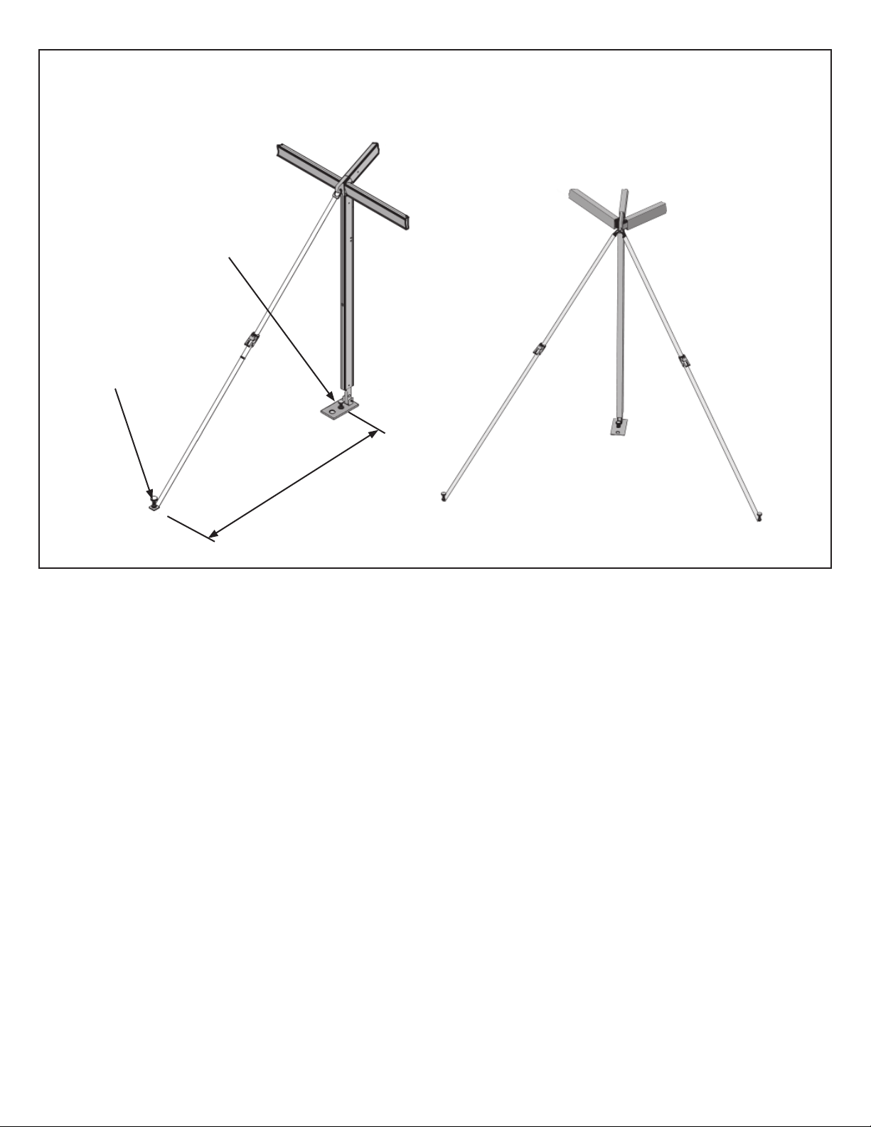
WEB GUY - STAKING GUIDELINES
REQUIRED DISTANCE OUT BETWEEN FRAME UPRIGHTS AND STAKE
LINE IS EQUAL TO THE UPRIGHT HEIGHT.
(FOR EXAMPLE, 8’ UPRIGHT = 8’ STAKE-OUT DISTANCE.)
(1) 30” Stake through each
base plate. Drive into
ground as far as possible.
42” Stake driven through
stake plate. Stake must be
driven into ground as far as
possible. (1) per upright as
shown for Gabled End Units.
UPRIGHT HEIGHT
STAKE-OUT DISTANCE =
Corner staking is at
90º on hip ends.
7
Page 8

ASSEMBLING THE CROSS BEAM
Begin the hip end installation by assembling the cross-beam
section of the hip end framing with the eave bars connected,
(see fig. 4)
The following illustrations show details of each step to complete this assembly phase. Notice that the uprights (legs) are
not installed at this time. They will be added with the help of
a tent jack after the hip end upper frame is completely assembled.
END RAFTER
W/ HOOK
EAVE
4
REMAINING
END EAVES
& HIPS
Appropriate pins are attached to the weldments. The long
pins pin vertically through the aluminum extrusions. The
short pins pin horizontally through the aluminum extrusions.
After completing each step on this page, the hip end frame
should resemble the drawing to the right.
PARTS LAYOUT
Begin by laying out the parts neatly in their
approximate location, as if the frame were
collapsed onto the ground.
JOINING CROSS BEAM AT RIDGE
RW
5
7
CROSS BEAM
RAFTERS
6
Install an Eave Weldment (EW) to the lower
(tapered) ends of each Rafter (R-20). Insert
the short pin provided thru the rafter (side-toside) to secure the connection.
ASSEMBLING THE HIP CROSS BEAM
R-20
EW
8
E-10
(SIDE)
EAVE
R-20
Slide the top (squared) ends of each Rafter (R-20) onto
the Ridge Weldment (RW) and secure with the short
pins provided on the weldment.
E-10 on opposite side
RAFTER W/ Hook (RH-20)
Install the Rafter w/ Hook (RH-20) to the center bracket
of the Ridge Weldment (RW), and let it lay on the ground
until the cross-beam is pivoted.
EW
At the Eave Weldment on both sides of the cross-beam,
slide eave bars onto the weldment and secure with the
long pins, allowing the eaves to stand vertically.
9
10
RW
Close-up of the Rafter w/ Hook (RH-20) being connected to the Ridge Weldment (RW). (Notice the
pivoting latch of the Rafter Hook.)
(RH-20)
INSTALLING HIP EAVES
At this time, the cross-beam
portion of the hip end should
be complete, with eave bars
standing vertically, as shown
(see fig. 4, above)
Caution: If you have
attached liner ropes, they
should be kept at least
partially coiled to prevent
them from becoming a trip
hazard during the remaining steps of the installation.
8
Page 9

COMPLETING THE HIP END
UPPER FRAME
In the following steps the upper frame of the hip end will be
completed (see fig. 11 to the right). Following this sequence
will result in a smooth assembly.
As this upper frame is completed, you should begin to position
the hip end close to its intended position.
In addition to the long and short pins used above, the corner
weldments have a thicker short pin that is used only for horizontal pinning through the lower end of the hip bar.
11
END EAVE
E-10
EW
Complete the end eave by joining each
Eave Bar (E-10) to the Eave Weldment
(EW), as shown, and pin with long pins.
HIP
CORNER
12
E-10 (SIDE)
END EAVE
CW
13
Insert a square arm of a Corner Weldment
(CW) to each outer end of the Eave Bar (E-
10) as shown and pin with a long pin.
15
E-10 (END)
CW
E-10
(RH-20)
(R-20)
Using the Rafter w/ Hook (RH-20) and the Eave Bars (E-10)
for leverage, pivot the cross beam to a vertical position, lining up the Eave Bars with the Corner Weldments at each
end of the end Eave Bar assembled in the preceding steps.
EW
PIVOTING THE CROSS BEAM
16
(RH-20)
(R-20)
E-10
(END)
E-10 (SIDE)
CW
14
The free ends of the Eave Bars used to pivot the cross
beam can now be attached to the Corner Weldments
and pinned vertically with a long pin.
RW
(R-20)
INSTALLING HIP BARS (H-20)
Install the upper end of each Hip Bar to the ridge weldment at the
top of the cross beam. To do this, first align the Hip Bar straight
in along side the Rafter w/ Hook, then swing the lower end of the
Hip Bar outward to the Corner Weldments and pin with the short,
thick pin.
17 18
(H-20)
(RH-20)
The free lower end of the Rafter w/ Hook can be
attached to the Eave Weldment (EW) at the center of
the end eave. Secure vertically with a long pin.
H-20
E-10 (SIDE)
CW
Close-up of the Hip Bar (H-20) connection to the Corner
Weldment (CW). Notice the slotted underside of the
hip bar designed to drop over the top arm of the Corner
Weldment.
E-10(END)
9
Page 10

INSTALLING UPRIGHTS UNDER
THE UPPER HIP FRAME.
Using the method shown, you should be able to install the NAVITRAC LT using only one NAVI-TRAC JACK.
You will lift one side of the Hip End and insert and pin the Uprights
onto the under fitting of each weldment. Then, move the jack to
the opposite side and install the remaining Uprights.
NOTE: To achieve proper balance, the NAVI-TRAC JACK
should be positioned 1 ft off center on the side Eave Bar (E-
10) in the direction of the peak of the frame (see fig. 20). Be
attentive to the balance of the frame should uneven terrain require
a slight shifting of this balance point.
HIP END
CROSS BEAM
HIP END FRAME
19
20
OFF-CENTER
Use the NAVI-TRAC JACK at 1 ft off-center of
the Eave Bar (in the direction of the peak) to lift
one side of the hip end upper frame. Insert the
uprights onto the bottom fitting of each weldment
and secure horizontally with a short pin.
NAVI-TRAC
JACK
INSTALLING UPRIGHTS (1st SIDE)
E-10
(SIDE)
INSTALLING UPRIGHTS (2nd
SIDE)
Repeat this procedure on the opposite side
Eave Bar (again 1 ft off-center in the direction of the peak), and install the opposite side
Uprights.
ADDING MIDDLE BAYS TO FORM A RECTANGULAR UNIT
The NAVI-TRAC LT hip end unit can be extended into a rectangle by adding
parallel middle bays as shown (fig. 23).
Each middle beam is constructed the same as the hip end cross beam,
except that uprights are attached before standing the beam to vertical. Also,
the connecting parts (Ridge, Eaves, etc) are first installed on the standing
beam, and the new middle beam is stood and then joined to them in the air.
Unlimited middle bays can be added, but when the unit exceeds 60’ in
length, and for each each additional 60’ of overall length, an X-cabled bay
must be included (see Appendix 1, fig. 50, 51 & 52 for a description of the
X-cabling).
This assembly section describes units with hip ends on both ends of the unit.
(For hip end-gabled end or purely gabled end units, see Appendix 1).
21
22
LIFTING CRADLE
INSTALLING UPRIGHT @ MID EAVE
To install an upright under the Eave Weldment
on the end eave, simply use a Lifting Cradle to
lift the Eave as shown.
23
HIP END
CROSS BEAM
25
24
E-10
Install Eave Bars (E-10) to the Eave Weldments of
the standing beam. Let the Eave Bars simply hang
in a horizontal position as shown above.
HIP CROSS BEAM
MIDDLE BEAM
E-10
EW
“FOOTER”
Construct the add-on beam with uprights attached and pivot it to
vertical as shown above. Note: workers must “foot” the base-
plates to prevent the baseplates from sliding out.
“FOOTER”
10
Page 11

26
MIDDLE BEAM
EW
E-10
27
RG-15
Secure the new middle beam by attaching the Eave
Bars (E-10) from the standing beam to the mid beam’s
Eave Weldment as shown above.
Repeat this process with the Ridge w/Hooks (RG-10) as
shown above. Again, use the long Eave Bar Cradle to
attach the opposite end.
COMPLETING AND STAKING THE HIP END FRAME
The final middle bay joins with the cross beam of the opposite hip end (see fig. 28 & 29). Position the second (facing) hip end 10’ from the last middle beam, and use Eave Bars (E-10), and Ridge Bars w/ Hooks (RH-10) to connect it to the standing frame structure.
THE LAST MIDDLE BAY
28
STAKE ALL BASE PLATES
HIP END UNIT WITH (2)
MIDDLE BAYS
STAKE ALL GUY CABLES
ACCORDING TO LOADS
SHOWN ON THE BLUEPRINT.
NOTE: SEE APPENDIX 1,
FIG. 51 & 52 FOR X-CABLING
REQUIREMENTS IN UNITS
EXCEEDING 60’ IN OVERALL
LENGTH
29
To finish out the unit, position a second, facing, hip end spaced 10’
from the last parallel middle beam and connect the purlins, ridge,
and eave bars just as in the preceding bay. Consult the blue print
for loading data for each baseplate location. Stakes alone may not
meet the loading requirement. It is the customer’s responsibility
to provide adequate anchoring to meet the loads.
FABRIC GUIDE BRACKET
Fabric is installed using the fabric wheeled guide
brackets and pull ropes thrown over the purlins
and eave bars from one side of the tent to the
other (see fig. 30).
To install the hinged Wheeled Guide Bracket,
slide the top over the external eye of the eave
weldment and pin in place using a Tension Lock
Pin. Spread the hinged bottom brace until the
lower end lodges in the tensioning slot of the
upright leg, as shown to the right (see fig. 31).
Using the butterfly set screws attach the Navi-Trac
Wheeled Panel Guide wheels into the open end
of the bracket at the hinged angle, as shown (see
fig. 32).
TOP OF BRACKET PINNED TO
THE OUTER EYE OF THE EAVE
WELDMENT
Fabric Kedar being fed between the angled
wheels of the panel guide.
Before installing fabric, all middle beams should be guyed
off, as shown. All guys are staked out from the upright at a dis-
tance equal to the height of the upright. If the breeze is strong,
the corner uprights should be guyed off as well. Later, the corner guys will be temporarily released while the fabric hip end is
being tensioned.
30
UPRIGHT
TOP OF GUIDE BRACKET
WHEELED PANEL GUIDE
WHEELED
PANEL GUIDE
TENSIONING
SLOT
BOTTOM OF GUIDE BRACKET
32
31
11
Page 12

INSTALLING THE HIP END PANEL
To install the hip end fabric panel, first install the Fabric guide
bracket on one side of the hip end cross beam, with the wheeled
guide facing toward the end of the unit (fig. 33).
From side to side, throw the snap end of one pull rope up and
over the hip end top framing so that the snap hangs near the
Fabric Guide Bracket.
If possible, position the Guide Bracket and the hip end fabric
bundle on the downwind side so that the direction of pull will be
into the wind. This way the breeze can help lift the fabric over
the hip end frame members.
Snap the pull rope to the pull web loop at the end of the kedar
strip on the hip end fabric panel (see diagram at bottom of this
page.) This rope will be pulled in line with with the cross beam,
from the opposite side of the tent (fig. 34).
Snap a second pull rope to the tension ring at the corner of the
fabric panel. This rope will help guide the fabric and prevent it
from riding up the hips and rafters as the panel is pulled across
the frame (fig.34).
Insert the leading edge of the kedar between the guide wheels
and pull the panel up and over.
FABRIC GUIDE
BRACKET
FACING THE END
OF THE TENT
PULLING PANEL
THROUGH CHANNEL
33
34
GUIDING OVER
FRAME MEMBERS
When the leading edge of the kedar reaches the eave weldment
on the opposite side, pull the corners of the fabric down over the
eye on the out side of the Corner Weldment, and install or reinstall the guy webs at both corners to protect the tent from the
wind load the hip panel will now exert on the frame (fig. 35 & 36).
CORNER PULLED
OVER WELDMENT
SAFE ATTACHMENT OF PULL
ROPES TO FABRIC
FOLD CURTAIN AND CATENARY BACK
ON TOP OF MID SO THAT THEY ARE
OUT OF THE WAY.
KEDAR
35
SNAP OF PULL ROPE MUST BE
FASTENED TO PULL WEB ON
UNDER SIDE OF FABRIC PIECES.
SNAP MUST FACE AWAY FROM
KEDAR.
FLAP - ONLY ONE
SIDE OF MID OR
END WILL HAVE
THE FLAP.
36
NOTE: TO ENSURE THAT MID
FABRIC GOES IN SMOOTHLY AND
TO MINIMIZE CHANCE OF DAMAGE
TO FABRIC, ALWAYS USE THE
WHEELED PANEL GUIDE TO FEED
KEDAR INTO FRAME CHANNELS
AND ALWAYS SNAP PULL ROPE TO
FABRIC AS SHOWN HERE.
U-8
GUY WEB
ATTACHED
CORNER
GUYS
12
DIAGRAM SHOWING UNDER
SIDE OF FABRIC AT EAVE.
Page 13

KEDAR CAPTURED IN
WHEELED GUIDES
CLOSE UP OF
37
GUIDE BRACKETS
38
PULLING KEDARS
THROUGH CHANNELS
INSTALLING THE MID PANELS
To install the mid panel, first attach Fabric Guide Brackets to both beams of the middle bay with the guide wheel assemblies of the two
brackets facing toward each other (fig. 37).
Throw the snap ends of (2) pull ropes up and over the frame from one side of the tent to the other, so that the snaps hang near the
Fabric Guide Brackets.
Feed the leading edge of each Middle Panel kedar through the gap in the guide wheels on each side of the Middle Panel and snap the
pull ropes to the pull web (See diagram at bottom of previous page and fig. 37 & 38). As the panel is pulled, the kedar will feed itself if
the fabric bundle is free of tangles (fig. 39).
39
13
Page 14

FABRIC TENSIONING
Adjacent top fabric panels are tensioned together
at each upright (leg) of the tent.
As shown at the right, the tension straps of each
catenary tensioning arch interlink through the pull
ring of the adjacent fabric panel (fig. 40). Both
tension straps then join at the top double hook
of a web ratchet strap. The bottom of the web
ratchet strap is then hooked into a slot in the
upright and ratcheted so that the catenaries of
both top panels are tensioned at once (fig. 41).
When tensioning a panel, be sure that it is
secured by the web ratchets on both sides of
the tent before beginning to ratchet either of the
catenaries tight, otherwise the panel may simply
move toward the opposite side.
After the catenary is tensioned, velcro the adjacent valances together (fig. 42).
40
41
MID
#1
PULL
RING
TENSION
STRAP #2
TO SLOT IN
UPRIGHT
MID
#2 OR
HIP
TENSION
STRAP #1
WEB RATCHET
DOUBLE HOOK
NOTE: IN THIS PHOTO, THE TENT WALLS
HAVE ALREADY BEEN INSTALLED.
GUY WEB
DOUBLE
MID
#1
HOOK
VELCRO FLAP
MID #2
OR HIP
TENSION
STRAPS
WEB
RATCHET
UPRIGHT
DOUBLE
HOOK
TENSIONING SYSTEM COMPLETE
(SHOWN WITH WALLS INSTALLED)
14
Page 15

42
With the hip end tent complete, adjust the guy webs for even tightness. Note: guy webs are
staked out from the baseplates by a distance equal to the height of the uprights so that the
web angle is 45 degrees to the ground (fig. 43).
Walls are optional, but in the wind, the tent is safest when the walls are either all closed or
all open.
The Navi-Trac LT can also be configured in the following ways:
1. As a Guyed Unit With (2) Gabled Ends
2. As a Guyed Unit With (1) Gabled End and (1) Hip End
3. As a Guyed Unit With (2) Hex Ends
4. As a Guyed Unit With (1) Hex End and (1) Gabled or Hip End
3. As a Clearspan Unit with no Guys
For Proper Configuration of these frame variations, see Appendices 1 and 2.
15
Page 16

APPENDIX #1
(GABLED-HIP) AND (GABLED-GABLED) END UNITS
GABLED-HIP END UNITS
In the Hip-Gable construction, you should build the hip end first to
provide stability to the structure. Then, using the same techniques as
shown earlier, continue standing middle beams as desired.
At the final end beam, be sure to attach the Gabled End Rafter Fittings
and the End Uprights themselves before standing the beam (see fig. 44)
Notice that all Gabled ends require the X-cabling of the end bay (see fig.
43). Also, when the structure exceeds 60 ft of length, and additional XCabled bay is required (see fig. 54). Parts for the Gabled End construction are listed below. For assembly procedure, see the top of page 21.
PARTS FOR 20’ HIP-GABLED PER PER
LABEL OR GABLED-GABLED UNITS 20’ 10’
(LETTER (GABLED COMPONENTS IN ITALICS) POSITION ID PART GBL END EXTENSION MID
ON DWG) COMPONENT DESCRIPTION CODE CODE # KIT (#1351) KIT (#1350)
TOP EXTRUSIONS WITH CHANNELS:
E-10 EAVE - 10’ 8004400 0 2
RG-10 RIDGE W/ HOOKS - 10’ 8004405 0 1
R-20 RAFTER 20’ 8004425 0 2
GWE GABLED END WING EAVE - 10’ 8004460 2 0
GU GABLED END UPRIGHT W/ TOP FITTING 8004465 1 0
GABLED-HIP END FRAME
X-Cabling stabilizes
the Gabled End Bay
43
PURLINS AND BRACES:
K8 KNEE BRACE (FOR CLEARSPANS ONLY) 3580650 0 [2]
UPRIGHTS:
U-8 UPRIGHT - 8’ 8004450 0 2
WELDMENTS, FITTINGS & PLATES:
BA BASEPLATES, ADJUSTABLE, 2-HOLED 8004505 0 2
BAG BASE PLATE, GABLED END, ADJ, 2-HOLED 8004510 1 0
RW RIDGE WELDMENTS ASSEMBLY 8004545 0 1
EW EAVE WELDMENT W/ PINS 8004530 0 2
GWL GABLED END WELDMENT (L) 8004535
GWR GABLED END WELDMENT (R) 8004540
CABLES
X8-10 X-CABLE, 8’ UPRIGHT 10’ BAY GREEN NAVLTCS-BAY10-U8 8004550 4 0 (unless over 60’ L)
X9-10 X-CABLE, 9’ UPRIGHT 10’ BAY (FOR CS ONLY) GREEN NAVLTCS-BAY10-U9 8004585 [4] 0
X10-10 X-CABLE, 10’ UPRIGHT 10’ BAY (FOR CS ONLY) GREEN NAVLTCS-BAY 10-U10 8004495 [4] 0
XR-10 X-CABLE, RAFTER, 10’ BAY BLUE NAVLT-BAY10 8004565 4 0 (unless over 60’ L)
10
10
NOTE: See pages 7 through 12 for staking and guying requirements.
44
Gabled End Frames
If you plan to use the gabled end frame on either end of the unit, it will be easier
to install the Gabled End Upright (GU) while that end beam is still on the ground.
To install, pin the Gabled End Top Fitting to the Tab at the bottom of the Ridge
Weldment. Note: if desired the hardware brackets on the outside of the Ridge
Weldment can be removed to give a cleaner outer appearance.
R-20
GU
Caution: If you will be using Gabled Ends on both ends of your unit,
please refer to the section on Frame safety for Gabled Ends at the bottom
of page 17.
RW
R-20
16
Page 17

Gabled End Frame Assembly
If the End Upright was not installed to the Gabled End Weldment
while the end beam was on the ground, it will have to be installed
from a ladder. (See fig. 44 for correct installation of the End Rafter
Fittings).
Next, install the hooked bar end connector of the wing eave bar into
the corner upright bracket (fig. 45). Then, drop in the angled end
on the remaining bracket of the end upright (fig. 46). Repeat this
process for the opposite end wing eave bar, then stake down the
uprights.
Installation of Gabled End
Fabric Panels
To install the gabled end fabric, first insert one of the wheeled panel
guides and bracket on the end beam with the wheels facing out.
Insert the fabric kedar of one half the end into the upper channel
and use the push pole to slide the half panel to the peak (fig. 47).
Repeat this from the other side of the structure. Then join the two
half panels at the peak using the carabiner to fasten the rings and
lace down the center line using a standard loop and grommet tent
lacing pattern.
45
46
47
Attach the web ratchet to the triangular metal ring and to the tension
hole in the end upright and ratchet into tension (fig. 48).
48
GABLED END
VALANCE
WR
GU
STANDARD LOOP &
GROMMET LACE WITH
WEATHER FLAP.
LEFT
SIDE
RIGHT
SIDE
17
Page 18

UNITS WITH 2 GABLED ENDS - - FRAME SAFETY
49
A structure with (2) Gabled Ends lacks the initial stability normally provided by the hip end frame during installation of the
first middle beams. To compensate for this, we have provided
Installation Safety Guys to stabilize the first standing beam until
additional beams are connected to it. (see fig. 49)
Notice that the first beam raised is actually the second beam of
the frame system (fig. 49). In this way, the first beam raised
can be safely guyed to the base plates of the adjacent beams
on each side.
Next, the first beam of the layout is raised and joined to the
second (fig. 50). When X-cabling has been installed in this
first bay, the structure is secure for standing the remaining
beams in the same way previously shown for standing middle
beams (fig. 51).
50
Caution: While standing beams, be sure to “foot” the base-
plate so that the beam does not slide out from under the workers pushing it up.
After the first bay has been X-cabled, the installation safety
guys can be removed.
Gabled Ends are installed in the same way as the Hip-Gabled
units described above.
As before, be sure to guy out the frame before installing fabric.
Note: When the overall length of the unit exceeds 60 ft, an
additional bay must be X-cabled for stability (see fig. 52). At
no place in the length of the unit should there be more
than 60 consecutive feet of non-X-cabled frame.
51
52
Additional
X-Cabled Bay
18
Page 19

Appendix #2
20’ Navi-Trac LT Clearspan
(MAX)
60’
X-CABLED
BAY
10’
54
KNEE BRACES
ON INNER
BEAMS
20’
10’
CLEARSPAN UNITS EXCEEDING 60 FT IN LENGTH
X-CABLED BAY FOR
EACH ADDITIONAL
60 FT OF LENGTH
53
KNEE BRACES
ON INNER
BEAMS
20’
10’
CLEARSPAN UNITS UP TO 60 FT IN LENGTH
ASSEMBLY OF 20’ NAVI-TRAC CLEARSPAN (CS) UNITS
10’
(MAX)
70’
NAVI-TRAC LT Clearspan (CS) units are installed with the same procedure as the Gabled-Gabled End or Hip styles previously described, except that the baseplates are hinged, allowing the beams to be pivoted to vertical. For this reason,
the Clearspan footprint can be laid out ahead of time, with baseplates positioned and anchored to the ground. The 20’
Clearspan units differ from the LT (Lite) unit in the following important ways:
1. The 20’ Clearspan units have no external guy webs.
2. All inner beams are Knee Braced on both sides of the unit (see fig. 53).
3. The baseplates of all uprights (legs) are hinged (see parts # BH & BHG on page 4), so that the beam
can be pivoted to vertical after the baseplate has been secured to the ground or to appropriate footings.
Additionally, the base plate has (4) holes for staking or anchoring.
The Gabled End technique of standing the second beam of the unit first and stabilizing it with safety guys should
still be used in installing the Clearspan units in order to provide a safe procedure in the initial stages of assembly
before the first bay is stabilized.
NOTE: (2) 1” x 30” steel stakes are provided for each baseplate. The actual loading may require additional stakes
or other anchoring methods to properly meet the loads defined on the blue print or the summary of engineering
analysis. It is the customer’s responsibility to insure that proper anchoring is used to meet the required loads.
19
Page 20

To Attach Ground Bars At Gable End Corner of CS NT-LT
Ground Bar (Gable
End)
CS (4) Hole Gable End Corner base plate
Ground Bar (Side)
Gable end ground bar pin fi ts
onto end of L-pin for attachment
of Gable end ground bar.
20
Page 21

EVANSVILLE, INDIANA
PHONE NUMBER
812· 867· 2421
FAX NUMBER
812· 867· 0547
Anchor products are of superior design and operate best within the parameters of these instructions. It is imperative
that the instructions be carefully read and COMPLETELY FOLLOWED. Please read installation instructions before the
installation or removal of this product. Installation instructions are available online at www.anchorinc.com or by calling
1-800-544-4445.
CAUTION:
1. For each installation, the installer is solely responsible for evaluating the site and the proper securing method
determined. Some soils require different staking or securing than that provided with the tent. Due to this variety of
soil conditions, these are the manufacturer’s suggested sequence of installation procedures. Anchor’s responsibility
is limited to the manufacture of the tent parts and materials. We are not responsible for methods that installers may
choose to erect and secure the tent to the ground.
2. The number of stakes suggested in the installation instructions do not necessarily meet all or any relevant codes
on the site of the tent installation. The number of stakes suggested will, in many cases, keep the tent erected,
however, due to various soil conditions; these stakes will be insuf¿ cient to keep the tent secure in high winds.
It is the tent installer’s responsibility, not the manufacturer, to determine the appropriate number of stakes to meet
the necessary wind loads on the site. Regardless of the number of stakes we suggest, we make no representation
or warranty as to whether this speci¿ c number of stakes will meet the local tent code. Anchor does not, nor can
it make any suggestions, representation, or warranties about the adequate staking required at each speci¿ c
installation site. Staking information provided in the installation instructions is not a suggestion about what is
necessary to meet a site-speci¿ c load.
For additional important information, consult: “The IFAI Procedural Handbook For the Safe Installation and
Maintenance of Tentage” and the IFAI Pocket Guide “Pullout Capacity of Tent Stakes”, both available from
the IFAI Tent Rental Division or on our website.
3. Inasmuch as the weather is unpredictable, good judgment and common sense must be incorporated within
installation guidelines. It is the responsibility of the tent installer/maintainer to determine the severity of the weather,
proper time and method of installation and/or erection and disassembly. Note: We recommend that snow and
ice be removed from the tent surface as soon as possible because accumulation will damage the tent
or fabric structure. Please consult with our Engineering Department about the maximum loads for each
product.
This product has been manufactured to meet code requirements. For the safety of all occupants, evacuation is
recommended if threatening weather occurs, or if there is any doubt concerning the safe use of this product.
4. Proper safety equipment should be used at all times to insure a safe installation and take down. We suggest a
careful evaluation be made to determine safety equipment needed, such as hard hats, steel-toe shoes, safety
glasses and other as required. It is our desire that all installations are safe. Please be aware of hidden dangers
both underground, i.e., gas lines, water lines, electrical lines, etc. and above the tent such as power lines and
telephone lines.
5. Anchor stands behind its products in accordance with its standard Terms and Conditions of sale. A copy of our
Terms and Conditions of Sale can be obtained by contacting Anchor at the telephone number and/or address on
this document.
28.3 03-04-09
 Loading...