

Page 1
Assembly Instructions
Navi-Trac® Frame Tent
30’ Wide Hip-End System
Please read all assembly / installation instructions before the installation or removal of this product.
WEB
EC4714
5.0”
EVANSVILLE, INDIANA
2.3”
1100 Burch Dr., Evansville, IN 47725
Ph. 812-867-2421 • Fax. 812-867-0547
E-mail: tents@anchorinc.com • www.anchorinc.com
NAV30H 1113
Page 2

Table of Contents
PAGE NO. DESCRIPTION
3 INTRODUCTION
INSPECT SITE
FRAME TERMINOLOGY
4 COMPONENT ILLUSTRATIONS
5 30’ NAVI-TRAC COMPONENT LIST TABLE
HARDWARE LOCATION CHART
6 SAFETY GUIDELINES
7 SQUARING THE TENT - FOOTPRINT LAYOUT
8 LAYOUT END MODULE COMPONENTS
CONSTRUCT FIRST BEAM
9 ASSEMBLING & COMPLETING HIP END TOP FRAME
10 SUMMARY OF STEPS FOR SQUARE TENT
INSTALLING FABRIC ON HIP ENDS
11 LIFTING TOP FRAME
12 WEB GUY - STAKING GUIDELINES
13 TENSIONING AND GUYING
14 HIP END MODULES FOR RECTANGULAR UNITS
15 UNITS WITH (1) MIDDLE BAY
INSTALLING MID BAY PURLINS AND EAVE/RIDGE BARS
16 PURLIN SUPPORTS IN 20’ MID BAYS
INSTALLING MID PANEL
17 SAFE ATTACHMENT OF PULL ROPES
UNITS WITH (2) OR MORE MID BAYS
18 X-CABLED BAYS
30’ NAVI-TRAC COMPLETE ILLUSTRATION
19 WALL INSTALLATION
20 GROUND BAR KEEPER
21 LIMITS OF LIABILITY
2
Page 3
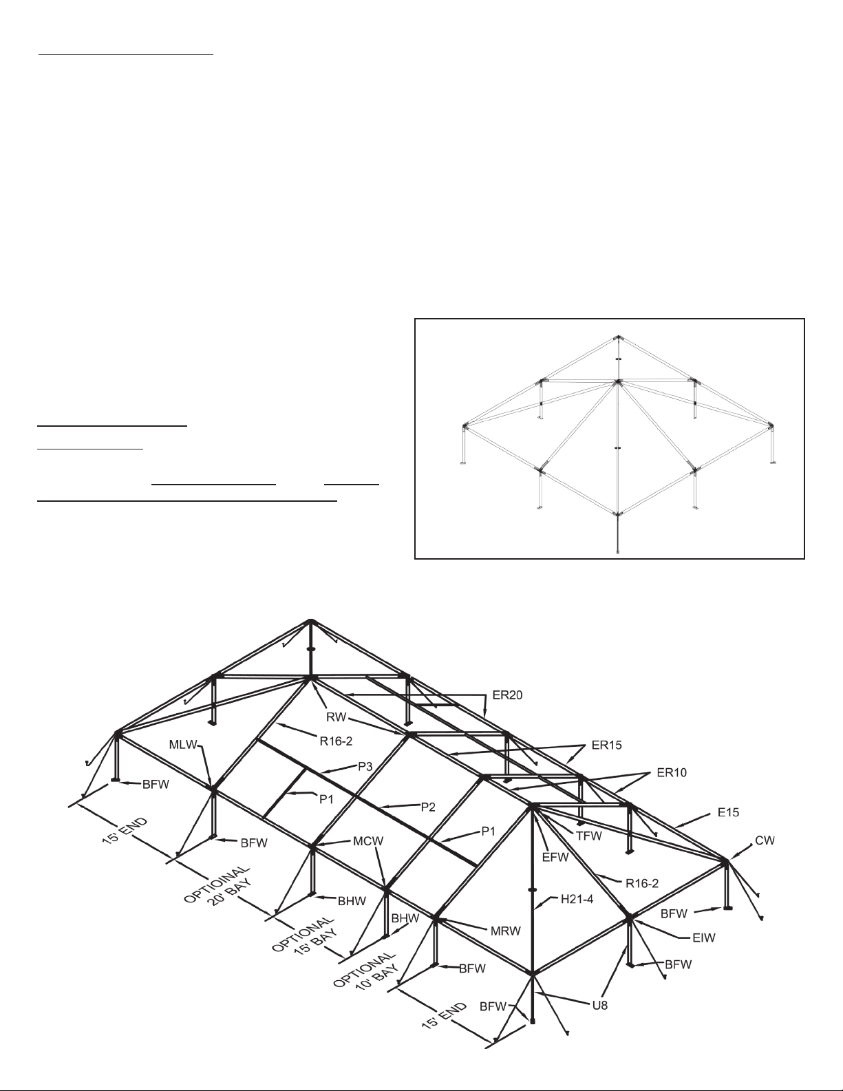
INTRODUCTION:
The NAVI-TRAC frame configuration is based on the hip roofed square tent shown below.
Hip bars connect corners to the peak, and rafters connect eave bars to the peak. The square can be extended into a rectangle by adding 10’, 15’ or 20’ bays made up of rafters and the appropriate ridge/eave bars (see below). In the square
tent, female eave bars and rafters are connected to eave weldments by rigid slip joints. Hip bars and eave/ridge bars and
rafters in the middle bays use easy to install drop-in fittings.
The NAVI-TRAC frame is made up of extruded aluminum members joined by weldments such as corner weldments, ridge
weldments, eave weldments, etc. The aluminum frame members themselves are extruded with channels into which the
NAVI-TRAC fabric “kedar” is fed.
The first bay added to the square tent shape is a “starter” bay. This starter bay allows a slip fit connection to the square
tent eaves on one end of the weldment and a drop-in connection for the new starter bay eaves on the other end of the
weldment.
Subsequent bays added to the unit are “extension” bays. Extension bays allow drop-in connections on both ends of the
eave weldments.
The chart on page 5 lists components needed for the 30’
x 30’ square tent, the first (starter) extension, and for each
additional extension to be added to the unit. Note: starter
mids or bays and extension mids are available in options
of 10’, 15’ or 20’ increments of length, as shown.
SQUARE TENT
FRAME
INSPECT SITE
CAUTION:
Consult your local utility locator service or the National
Utility Locating Contractors Association (NULCA) prior to
installation.
Prior to actual tent assembly, be sure to look up, down,
above & below for obstacles, pipes, wires, trouble, etc.
30’ Navi-Trac Frame Terminology
3
Page 4
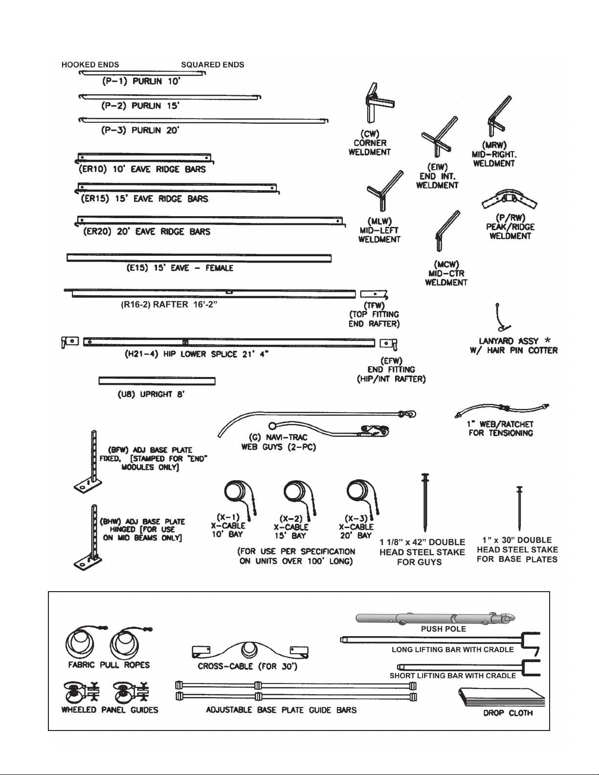
30’ NAVI-TRAC COMPONENT ILLUSTRATIONS
INSTALLATION TOOLS
4
Page 5
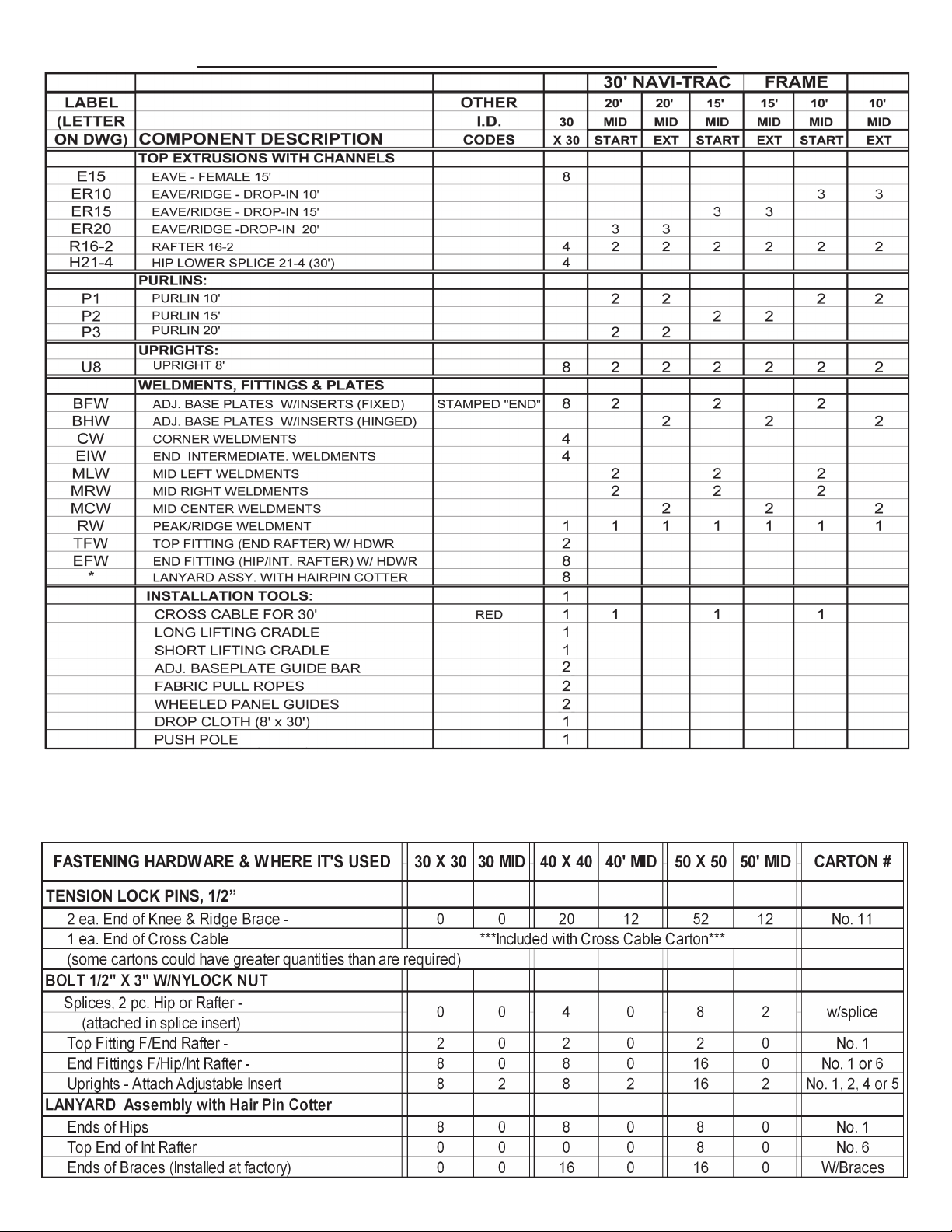
30’ NAVI-TRAC COMPONENT LIST
OTHER COMPONENT NOTES:
1. FOR X-CABLES FOR UNITS 100’ OR LONGER, SEE PAGE 17 FOR LABELING, QUANTITIES, AND INSTALLATION.
2. STAKES AND GUYS ARE NOT INCLUDED IN THIS TABLE. SEE STAKING GUIDELINES ON PAGE 12.
HARDWARE LOCATION CHART
5
Page 6

NAVI-TRAC Installation Safety Guidelines
Your installation techniques will evolve to fit the needs of your clients, the experience level of your crews, the nature of
other tentage on-site, and the equipment that you have most readily available. We encourage you to begin with a crew of
(4) workers and only reduce this number as your experience level allows you to do so
safely. Whatever techniques you adapt for your crews, we encourage you to keep safety utmost in mind.
Please read through this assembly manual completely before beginning your installation. Be sure the proper equipment,
crew and safety precautions are in place. We hope that you enjoy the design features of the NAVI-TRAC each time the
unit is installed.
1. It is recommended that workers wear safety shoes and hard-hats on site.
2. When moving beam sections by hand, use proper lifting techniques to protect the back, and
avoid pinching fingers while making hardware connections.
3. Never permit bystanders or uninvolved to stand or walk even briefly in the falling path of a beam as it is being
raised or lowered.
4. Be aware to avoid contact of beams with any overhead power lines near the site.
5. When anchoring the structure, avoid all underground power lines and gas lines or other utility
easements. Local authorities should be able to map the location of these obstacles.
6. Keep site clear of debris to avoid tripping, especially while carrying components or bundles of fabric.
7. Do not drag bundles of fabric on concrete, asphalt, or ground as this can cause damage to the
fabric from abrasion through the bag.
8. When lifting the NAVI-TRAC frame, be sure to use the heavy duty NAVI-TRAC frame lift. The standard
Anchor frame lift was not designed for the weight of the NAVI-TRAC frame. When lifting each side of
an end section, (2) NAVI-TRAC frame lifts should be used.
9. Before pivoting beams to vertical, clear the area
10. Before pivoting middle beam, install the cross-cable for safety bracing. The cross-cable should be
removed only after knee braces have been installed to support each middle beam.
11. NOTE: Hinged baseplates should be used only on middle beams supplied as “extensions” and not as
a component of an end module. End module plates should all be fixed, and end module eave
connections should be rigid, slip joints. Use of hinged baseplates in the end module could cause the
end module to collapse during installation.
12. When using ladders to make peak connections, be sure the ladder is tall enough that workers can
reach the peak from a ladder step consistent with the safety recommendations for the ladder being
used.
13. For any NAVI-TRAC of 100 ft or more in length, the uprights and rafters of one middle bay must be
cross-cabled on both sides in an “X” fashion for each 100 ft. of length (see illustration on page 18.)
of items that could cause tripping or slipping.
14. For proper loading and anchoring information, consult the appropriate NAVI-TRAC blueprint available
from Anchor Industries Inc.
15. Before installing fabric, verify that all hip pins are properly seated into weldment fittings and
secured by lanyard pins.
16. The installation method described herein requires coordination of tasks between workers. A
safe installation is dependent on alertness and coordination.
6
Page 7
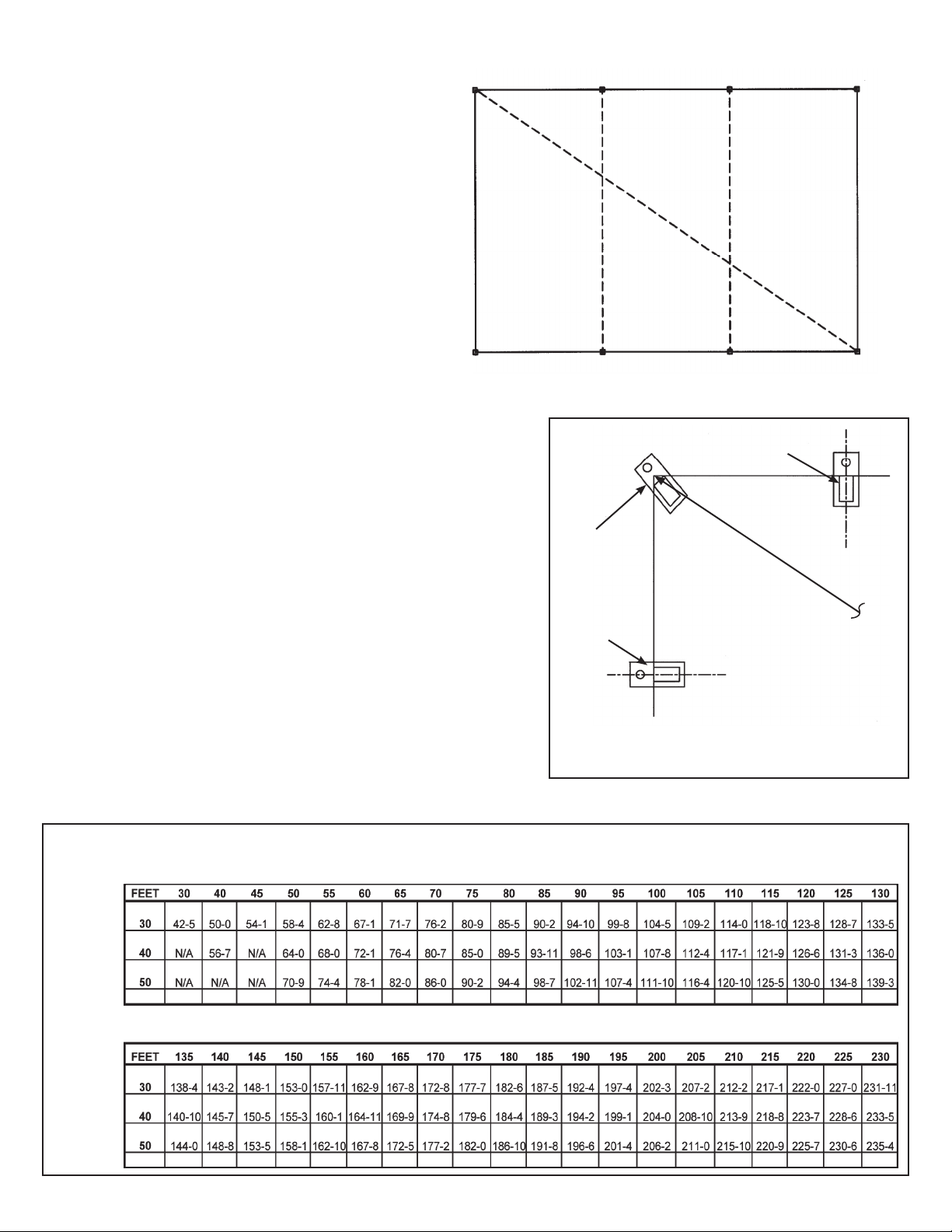
SQUARING THE TENT
FOOTPRINT LAYOUT
LOCATING
THE FOUR
PRIMARY
CORNERS
B
WIDTH OF TENT
LENGTH OF TENT
C
DIAGONAL
A
DIRECTIONS FOR SQUARING THE TENT
1. USE A TAPE MEASURE TO MARK THE ENDS OF A LINE FOR ONE END (A TO B
ABOVE) EQUAL TO THE EXACT WIDTH OF THE UNIT.
2. HOLD THE “0” END OF ONE TAPE AT POINT “A” AND THE “0” END OF ANOTHER
TAPE AT POINT “B”.
3. EXTEND THE FIRST TAPE ALONG ONE SIDE OF THE UNIT TO A MEASUREMENT EQUAL TO THE EXACT LENGTH OF THE TENT.
4. CONSULT THE CHART BELOW TO FIND THE DIAGONAL FOR THE TENT YOU
ARE BUILDING.
5. EXTEND THE SECOND TAPE TO A MEASUREMENT EXACTLY EQUAL TO THIS
DIAGONAL.
6. BRING THE TWO TAPES TOGETHER SO THAT THE LENGTH MEASUREMENT
OF ONE LIES DIRECTLY ON THE DIAGONAL MEASUREMENT OF THE OTHER.
PULL THE TAPES TIGHT AND MARK THEIR INTERSECTION. THIS WILL LOCATE A
FAR CORNER (POINT “D” ABOVE).
7. SWITCH TAPES SO THAT TAPE 1 (ABOVE) MEASURES THE DIAGONAL AND
TAPE 2 (ABOVE) MEASURES THE LENGTH. THIS WILL LOCATE POINT “C”
ABOVE.
8. WITH THE FOUR PRIMARY CORNERS LOCATED, LAY OUT BASEPLATES AND
UPRIGHTS ACCORDING TO THE DIAGRAM TO THE RIGHT AND BEGIN ASSEMBLY,
DOUBLE-CHECKING FROM TIME TO TIME TO MAKE SURE THE SQUARE FOOTPRINT IS BEING MAINTAINED.
D
SIDE
INTERMEDIATE
UPRIGHT
DIAGONAL
BASEPLATE
C/L
END
INTERMEDIATE
UPRIGHT
C/L
OUTER DIMENSIONS ARE
OUTSIDE-TO-OUTSIDE
INTERMEDIATE DIMENSIONS
ARE CENTER-TO-CENTER
DIAGONALS FOR SQUARING FOOTPRINT
LENGTH OF TENT
DIAGONAL SHOWN IN FEET-INCHES (TO NEAREST INCH)
WIDTH OF TENT
7
Page 8

LAYOUT END MODULE COMPONENTS
HOOK THE END RAFTER TOP FITTING ONTO THE
PEAK/RIDGE WELDMENT. THEN SLIDE THE END
RAFTER ONTO THE BOTTOM OF THE END FITTING
AND BOLT.
LANYARD
W/ COTTER
PIN
END
FITTINGS
HIP LOWER
SPLICES
END
FITTINGS
NOTE: ON END MODULES, EAVE FITTINGS FOR BOTH
EAVES AND RAFTERS ARE RIGID SLIP JOINTS.
CROSS-CABLE
NOTE: ONLY FIXED-BASE UPRIGHTS ARE
TO BE USED IN END MODULES. HINGED
BASE UPRIGHTS ARE FOR MIDDLE BEAMS ONLY AND
COULD CAUSE COLLAPSE DURING INSTALLATION IF
USED IN AN END MODULE.
HEAVY DUTY NAVITRAC FRAME LIFTS
FIXED-BASE
UPRIGHTS
CONSTRUCT FIRST BEAM
FOR EASE OF ASSEMBLY,
MAKE CONNECTIONS IN
ORDER AS NUMBERED.
INSTALL CROSS-CABLE AND ADJUST
TURNBUCKLE UNTIL SPAN = 30’
(APPROX. HALF OPEN). AFTER
FABRIC IS TENSIONED, CROSSCABLE MAY BE REMOVED, IF
DESIRED.
AS BEAM IS PIVOTED TO
VERTICAL, THE EAVE BARS
ACT AS COUNTER-WEIGHTS
TO MAKE THE LIFTING EASIER.
1
2
OPTION: IF YOU ARE ASSEMBLING A SQUARE UNIT,
THE TRAILING END INTERMEDIATE RAFTER CAN
BE ATTACHED TO THE PEAK NOW TO AVOID LATER
CONNECTING IT FROM A LADDER.
7
6
4
5
3
8
Page 9

ASSEMBLING HIP END TOP FRAME
FOR EASE OF ASSEMBLY,
MAKE CONNECTIONS IN
ORDER AS NUMBERED.
5
4
3
LANYARD
W/ HAIR PIN
COTTER
1
2
7
6
HEAVY-DUTY
NAVI-TRAC
FRAME LIFTS
FIXED-BASE UPRIGHTS
(FOR END MODULES)
HIP LOWER SPLICES
HIP END
FITTINGS
HIP END
FITTINGS
COMPLETING HIP END TOP
FRAME
INSTALL DROP-IN HIPS
INTO PEAK AND CORNER
WELDMENTS & SECURE
WITH LANYARD PIN.
IF YOU ARE CONSTRUCTING AN EXTENDED
RECTANGULAR TENT, INSTALL FABRIC NOW.
IF YOU ARE CONSTRUCTING A SQUARE TENT,
PROCEED TO THE NEXT STEP.
USE LIFTING CRADLES AS
NEEDED TO MAKE HIP-PEAK
CONNECTIONS
BOLT END FITTINGS INTO
TOP AND BOTTOM ENDS OF
HIP, CAPTURING LANYARD
TERMINAL BETWEEN HEAD
OF BOLT AND THE HIP
EXTRUSION.
9
Page 10

SUMMARY OF STEPS FOR
COMPLETING THE SQUARE TENT
1. INSTALL OPPOSITE EAVES, RAFTERS, HIPS AND
HIP BRACES TO COMPLETE SQUARE FRAME.
2. USE PULL ROPES TO PULL TOP FABRIC KEDAR
FOR EACH END UP AND OVER THROUGH THE
CHANNELS ON EACH SIDE OF THE RAFTERS
THAT ARE ALIGNED WITH THE RIDGE BRACE.
3. LET FABRIC LAY LOOSELY ON TOP OF FRAME.
SECURE WITH ROPES AS NEEDED AGAINST
THE BREEZE.
4. USE HEAVY-DUTY NAVI-TRAC FRAME LIFTS TO
LIFT FRAME ONE SIDE AT A TIME TO INSERT
UPRIGHTS UNDER THE TOP FRAME.
5. INSTALL KNEE BRACES AT ALL INTERMEDIATE
UPRIGHTS AS THEY ARE INSTALLED.
6. STAKE BASE PLATES USING STAKING LAYOUTS.
7. USE WEB/RATCHETS TO TENSION CATENARY
FABRIC ARCHES TO UPRIGHT LEGS.
SQUARE UNIT TOP
FRAME COMPLETE
8. GUY TENT OUT AND STAKE. CONSULT STAKING
GUIDELINES ON PAGE 12.
INSTALLING FABRIC ON HIP END FRAMES
NOTE: BEFORE INSTALLING FABRIC,
INSPECT THE FRAME TO ENSURE ALL
HIP PINS ARE PROPERLY SEATED IN THE
WELDMENT FITTINGS AND SECURED
WITH LANYARD PINS.
BE CAREFUL TO AVOID
SNAGGING FABRIC ON OPEN
ENDS OF END INTERMEDIATE
RAFTERS HERE.
PULL FABRIC UP AND OVER THROUGH CHANNEL IN NAVI-TRAC
RAFTER EXTRUSIONS. EACH HIP END IS ONE-PIECE. LET FABRIC
TAILS HANG LOOSE UNTIL FRAME HAS BEEN LIFTED AND UPRIGHTS
HAVE BEEN INSTALLED.
FABRIC STRAPS ON
UNDERSIDE MUST
FASTEN TO HIP.
BE CAREFUL TO AVOID
SNAGGING FABRIC ON OPEN
ENDS OF END INTERMEDIATE
RAFTERS HERE.
NOTE: TO ENSURE THAT END FABRIC
GOES IN SMOOTHLY AND TO MINIMIZE
CHANCE OF DAMAGE TO FABRIC, ALWAYS
USE THE WHEELED PANEL GUIDE TO FEED
KEDAR INTO FRAME CHANNELS. SEE PAGE
17 FOR INFORMATION ON HOW TO ATTACH
PULL ROPES TO FABRIC.
RAFTER
WHEELED PANEL GUIDE
INSERT FINGERS OF WHEELED PANEL GUIDE INTO
OPEN END OF RAFTER AND WELDMENT. TIGHTEN
BUTTERFLY NUT. REVERSE FOR OPPOSITE SIDE
OF BEAM.
10
Page 11

LIFTING
TOP FRAME
(FIRST SIDE)
FABRIC NOT SHOWN
USING HEAVY-DUTY NAVI-TRAC FRAME LIFTS,
LIFT ONE SIDE OF FRAME. SLIDE UPRIGHTS
ONTO BOTTOM OF WELDMENTS ON THE RAISED
SIDE AND PIN. BE SURE ALL RAFTER AND HIP
PINS ARE SECURED WITH LANYARDS.
INSTALL UPRIGHTS.
INSERT BASEPLATES INTO UPRIGHTS AND BOLT.
NOTE: SQUARE FRAMES AND END MODULE FRAMES
MUST USE FIXED BASEPLATES. HINGED PLATES
ARE TO BE USED ONLY ON PIVOTING MIDDLE BEAMS
FROM THE EXTENSION FRAME SETS.
LIFT TOP FRAME
(SECOND SIDE)
FABRIC LIES LOOSELY ON FRAME UNTIL
UPRIGHTS ARE INSTALLED AND STAKED
NOTE: BEFORE TENSIONING
FABRIC, INSPECT THE FRAME
TO ENSURE ALL HIP PINS
ARE PROPERLY SEATED AND
SECURED WITH LANYARD PINS.
1. LIFT 2ND SIDE OF FRAME TO INSTALL OPPOSITE SIDE CORNER
AND INTERMEDIATE UPRIGHTS.
2. INSTALL UPRIGHT BRACES AT ALL INTERMEDIATE UPRIGHTS.
3. WHEN BRACES ARE INSTALLED, THE CROSS-CABLE CAN BE REMOVED.
11
Page 12

WEB GUY - STAKING GUIDELINES
REQUIRED DISTANCE OUT BETWEEN FRAME UPRIGHTS AND STAKE
LINE IS EQUAL TO THE UPRIGHT HEIGHT.
(FOR EXAMPLE, 8’ UPRIGHT = 8’ STAKE-OUT DISTANCE.)
(1) 30” Stake through
base plate. Drive into
ground as far as possible.
42” Stake driven through
stake plate. Stake must be
driven into ground as far as
possible. (1) per upright as
shown for Gabled End Units.
Corner staking is at
UPRIGHT HEIGHT
STAKE-OUT DISTANCE =
90º on hip ends.
* IMPORTANT NOTE: REFER TO CAUTION STATEMENT #2 FOR IMPORTANT WARNING ABOUT NUMBER OF STAKES
SUPPLIED. (SEE BACK PAGE OF THIS MANUAL)
THE INSTALLER MUST USE THE LOCAL SOIL CONDITIONS TO CALCULATE THE ACTUAL NUMBER
OF STAKES REQUIRED AND IS RESPONSIBLE FOR THE STAKING PATTERN AND CONFIGURATION.
ANCHOR PROVIDES ANCHORING PACKAGES FOR COMMON SOIL CLASSIFICATIONS; CONTACT YOUR TENT SALES
REPRESENTATIVE FOR MORE INFORMATION.
12
Page 13

TENSIONING AND GUYING
1. USE WEB/RATCHETS TO SECURE CATENARY ARCHES TO
UPRIGHTS, STAKE BASEPLATES BEFORE TENSIONING WEBS.
2. ATTACH GUY WEBS TO EAVE WELDMENTS AND STAKE OUT AT
A 45 DEGREE ANGLE (DISTANCE OUT = HEIGHT OF UPRIGHT,
USUALLY 8 FT. USE 42” STAKES PROVIDED.
3. AT DOUBLE-GUYED CORNERS, GUYS FORM A 90 DEGREE ANGLE.
FABRIC STRAPS ON UNDERSIDE
OF BOTH HIP END PANELS MUST
BE SECURED AROUND RAFTERS
AND HIP BARS, AS PROVIDED.
CATENARY
TAILS
DOTTED LINE REPRESENTS THE
RAFTER THAT IS IN LINE WITH THE
PEAK/RIDGE WELDMENT AND INTO
WHICH FABRIC IS FED THROUGH
CHANNELS.
TOP
TENSIONING
WEB (RIGHT)
W/ RING
TENSIONING RINGS
TENSIONING WEB
(LEFT) W/ RING
UPRIGHT
WEB/
RATCHET
OVERLAPPED
CATENARY
TENSIONING METHOD:
1. PASS RING OF LEFT TENSIONING WEB
THROUGH OPPOSITE CATENARY RING.
2. PASS RING OF RIGHT TENSIONING WEB
THROUGH ITS OWN CATENARY RING (PASSING
OVER THE LEFT WEB).
3. CONTINUE RING OF RIGHT TENSIONING WEB
THROUGH OPPOSITE CATENARY RING.
4. OVERLAP BOTH TENSION RINGS. ATTACH
WEB/RATCHET AND TENSION DOWNWARD
AGAINST TENSION HOLE IN UPRIGHT. (CATENARY
RINGS SHOULD MOVE CLOSER TOGETHER AS
RATCHET IS TIGHTENED.)
TAILS
TRIANGLE
RING
WEB/
RATCHET
UPRIGHT
TOP
TOP
CATENARY
TAILS
TENSION RINGS
(OVERLAPPED)
CORNER TENSIONING METHOD:
1. PASS BOTH TENSION RINGS
THROUGH THE TRIANGLE RING.
2. OVERLAP THEM AND ATTACH
WEB/RATCHET TO TENSION
DOWNWARD.
TENSIONING
METHOD: ATTACH
WEB/RATCHET TO
TRIANGLE RING
AND TENSION
DOWNWARD.
13
Page 14

HIP END MODULES
FOR RECTANGULAR UNITS
THE RECTANGULAR UNIT IS SIMPLY
(2) HIP ENDS FACING EACH OTHER
AND SEPARATED BY PARALLELBEAMED MIDDLE BAYS.
FABRIC NOT SHOWN
LIFT FIRST SIDE OF FRAME AND
SLIDE UPRIGHTS ONTO BOTTOMS
OF EAVE WELDMENTS AND PIN.
NOTE: ONLY FIXED-BASE
UPRIGHTS ARE TO BE USED
IN END MODULES.
FOR RECTANGULAR UNITS, FIRST CONSTRUCT
HIP ENDS, INSTALLING FABRIC LOOSELY AND
RAISING EACH SIDE TO INSTALL UPRIGHTS,
(JUST AS IN THE SQUARE TENT ON PRECEDING
PAGES.)
COMPLETING THE HIP END
LIFT SECOND (OPPOSITE) SIDE OF
HIP END AND PIN UPRIGHTS INTO
POSITION. WHEN ALL UPRIGHTS
ARE SECURE, THE CROSS-CABLE
CAN BE REMOVED.
FABRIC NOT SHOWN
HIP END FABRIC INSTALLED THE
SAME AS ON SQUARE UNITS (SEE
ILLUSTRATION ON PAGE 10)
14
Page 15

UNITS WITH (1)
MIDDLE BAY
(2) END MODULES
FACING EACH OTHER.
ADJUST TO DESIRED SPACING
AND FIT END CONNECTORS OVER
GUIDE PEGS ON BASEPLATES.
NOTE: FOR FREQUENT INSTALLATIONS,
THE PURCHASE OF A 2ND GUIDE BAR
COULD BE HELPFUL.
THE EXTENDED RECTANGULAR UNIT ALWAYS INCLUDES (2) HIP END
MODULES FACING EACH OTHER WITH THE DESIRED NUMBER OF
10’, 15’ OR 20’ MIDDLE BAYS SEPARATING THEM. NOTE: UNLIKE
THE RIGID EAVE AND LOWER RAFTER CONNECTIONS OF THE END
MODULE, MIDDLE BAYS USE DROP-IN PURLINS AND EAVE/RIDGE BARS.
NOTE: FABRIC ONLY INDICATED, SO
THAT FRAME WILL BE MORE VISIBLE.
NOTE: ONLY FIXED-BASE
UPRIGHTS ARE TO BE
USED IN END MODULES.
INSTALLING MID BAY PURLINS AND EAVE/RIDGE BARS
FOR EASE OF ASSEMBLY,
MAKE CONNECTIONS IN
ORDER AS NUMBERED.
FOR PURLINS & EAVE/RIDGE BARS,
INSTALL HOOK END FIRST, THEN
THEN 90 DEGREE OPPOSITE END.
1
2
4
3
5
NOTE: FABRIC ONLY INDICATED, SO
THAT FRAME WILL BE MORE VISIBLE.
15
Page 16

PURLIN SUPPORTS IN 20’ MID BAYS
IN 20’ MID BAYS, INSTALL A SUPPORT
PURLIN BETWEEN THE EAVE AND THE
PURLIN AT THE MID-RAFTER LOCATION.
THIS SUPPORT WILL BRACE AGAINST
INWARD DEFLECTION OF THE EAVE BAY
THAT COULD OTHERWISE RESULT
IN WATER PONDING IN THE 20 FT BAY.
INSTALLING MID PANEL
PULL MID PANEL UP AND OVER THROUGH
CHANNELS IN RAFTER EXTRUSIONS.
NOTE: TO ENSURE THAT MID GOES
IN SMOOTHLY AND TO MINIMIZE
CHANCE OF DAMAGE TO FABRIC,
ALWAYS USE THE WHEELED PANEL
GUIDE TO FEED KEDAR INTO FRAME
CHANNELS. SEE NEXT PAGE FOR
INFORMATION ON HOW TO ATTACH
PULL ROPES TO MIDS.
WHEELED
PANEL
GUIDE
NOTE: HIP END FABRIC PANELS NOT SHOWN
SO THAT THE FRAME WILL BE MORE VISIBLE.
RAFTER
INSERT FINGERS OF WHEELED PANEL GUIDE
INTO THE OPEN END OF THE RAFTER AND
WELDMENT. TIGHTEN THE BUTTERFLY NUT.
REVERSE FOR OPPOSITE SIDE OF BAY.
16
Page 17

SAFE ATTACHMENT OF PULL
ROPES TO FABRIC
SNAP OF PULL ROPE MUST BE
FASTENED TO PULL WEB ON
UNDER SIDE OF FABRIC PIECES.
SNAP MUST FACE AWAY FROM
KEDAR.
KEDAR
FLAP - ONLY ONE
SIDE OF MID OR
END WILL HAVE
THE FLAP.
DIAGRAM SHOWING UNDER
SIDE OF FABRIC AT EAVE.
FOLD CURTAIN AND CATENARY BACK
ON TOP OF FABRIC SO THAT THEY
ARE OUT OF THE WAY.
UNITS WITH (2) OR MORE MID BAYS
FOR EASE OF ASSEMBLY,
MAKE CONNECTIONS IN
ORDER AS NUMBERED.
3
2
IN UNITS WITH MULTIPLE MIDDLE BAYS, THE SECOND HIP
END MODULE CAN BE ASSEMBLED AT THE SAME TIME AS
THE FIRST OR LATER AFTER THE MIDDLE BEAMS HAVE
BEEN INSTALLED.
WHEN FRAME IS COMPLETE, MID
PANELS ARE INSTALLED THE SAME AS
PREVIOUSLY SHOWN IN THE SINGLE MID BAY
CONFIGURATION.
PUSH POLE MAY BE USED TO HELP IN
PULLING UP MIDDLE BEAMS. INSERT
HOOK INTO U BAR ON RIDGE WELDMENT AND TWIST POLE TO LOCK
INTO PLACE. UNTWIST POLE TO DISENGAGE ONCE POLE IS RAISED.
1
ADDITIONAL GUIDE BARS
MAY BE PURCHASED
MIDDLE BEAMS THAT ARE NOT A PART
OF AN END MODULE USE THE HINGED
BASEPLATE (FOR PIVOTING TO VERTICAL).
FIXED PLATES ARE STAMPED “END” AND
SHOULD BE USED ONLY ON END MODULES.
17
Page 18

X-CABLED BAYS
STAKE PLATES AT PROPER SPACING BEFORE
INSTALLING THE X-CABLES. THEN, ADJUST
TURNBUCKLES UNTIL CABLE IS SNUG
RAFTER X-CABLES ARE
COLOR-CODED RED
AND LABELED 10, 15, OR
20 ACCORDING TO BAY
SIZE.
X-CABLING IS IDENTICAL
ON BOTH SIDES OF THE
STRUCTURE.
UPRIGHT X-CABLES ARE COLORCODED GREEN AND LABELED 10,
15, OR 20 ACCORDING TO BAY
SIZE.
NAVI-TRAC UNITS 100 FT. OR MORE IN LENGTH MUST HAVE AN X-CABLED
BAY NEAR THE MIDDLE OF THE UNIT (AND/OR EQUALLY SPACED) FOR
EVERY 100 FT. UNIT OF LENGTH.
FOR CABLE CONNECTIONS AT MID
PORTION OF RAFTERS, INSERT
THE BOLTS IN THE HOLES OF
THE RAFTER THAT ARE JUST
BELOW THE PURLIN CONNECTION.
PURLIN
REMOVE NUTS FROM THE BOLTS THAT PIN THE
BASEPLATE TO THE UPRIGHT. TURN BOLTS SO THE
THREADS ARE TO THE INSIDE (TOWARD CENTER OF
BAY). THREAD CABLE EYE NUTS ONTO BOLTS TO
SECURE THE CABLE.
THREADS SHOULD POINT INWARD
TOWARD CENTER OF BAY. THREAD
CABLE EYE NUTS ONTO EACH
BOLT TO SECURE THE CABLES AS
SHOWN.
SUBSTITUTE BOLTS FOR PINS
AT THE TOP OF BOTH UPRIGHTS
AND BOTTOM OF BOTH RAFTERS.
THREADS SHOULD POINT INWARD
TOWARD CENTER OF BAY. THREAD
CABLE EYE NUTS ONTO EACH BOLT
TO SECURE THE CABLES AS SHOWN.
30’ NAVI-TRAC
COMPLETE
WITH (2) 15’ MID BAYS
1. ALL ENGINEERING ON THE 30’ NAVI-TRAC WAS DONE WITH THE WALLS IN PLACE. (FULLY
ENCLOSED). SEE NEXT PAGE FOR SIDEWALL INSTALLATION.
2. INSTALL, STAKE, AND TENSION ALL GUY WEBS, AS SHOWN. TENSION FABRIC SO THAT ALL CATENARY
ARCHES ARE EQUIDISTANT BELOW THE EAVE BARS.
3. REVIEW PAGE 12 FOR GUYING AND TENSIONING INSTRUCTIONS.
18
Page 19

Wall Installation
Step 1
Determine which side of wall is inside
and out. Ground bar pockets are on
outside, Lace flap is on inside. Start by
feeding top of kedar edge into channel
opening until top of wall is as far as it
will go. (Figure A)
Insert the bottom edge of kedar into
channel opening and feed down until
wall is smoothly installed into upright.
Step 2
Starting with wall tab nearest the lace,
insert into slotted opening in bottom
channel of eave bar. Feed rest of wall
tabs into channel.
Step 3
Repeat with the matching half of the
wall.
Step 4
Lace wall starting at top of wall bringing top loop thru the top grommet of
matching half of wall to inside of wall.
Continue with this process looping next
loop thru grommet and then the upper loop until all loops are laced. (See
Figure B) Tie off bottom loop to keep
lace together.
Wall tabs
Channel
opening
Ground bar
pocket
Lace
Flap
Eave Bar
Outside View
Eave Bar
Channel
opening
Figure A
Velcro for
lace flap
Step 5
Slide ground bar (Figure C) thru pocket
on outside of wall. Fasten to frame using the ground bar keeper as noted on
next page.
Inside View
Lace loops thru
grommets
Figure B
Ground bar
Figure C
19
Page 20

Navi-Trac Ground Bar Keeper
Instructions
Upright prong fits into this part
of upright.
This end to outside
of tent.
Cross sectional view of
upright.
Groundbar keeper for intermediate upright.
Wall with kedar already
slid into upright.
Groundbar slid
into pocket.
Prong with no hole
inserts up into upright.
Groundbar keeper for Corners.
Corner Upright
Bottom View looking up
into upright with Groundbar keeper inserted.
Inserting keeper up into
bottom of upright on outside corner of tent.
Base Plate Inserted
into upright.
Slide groundbars onto
prongs and pin into place
as shown.
20
Page 21

EVANSVILLE, INDIANA
PHONE NUMBER
812· 867· 2421
FAX NUMBER
812· 867· 0547
Anchor products are of superior design and operate best within the parameters of these instructions. It is imperative
that the instructions be carefully read and COMPLETELY FOLLOWED. Please read installation instructions before the
installation or removal of this product. Installation instructions are available online at www.anchorinc.com or by calling
1-800-544-4445.
CAUTION:
1. For each installation, the installer is solely responsible for evaluating the site and the proper securing method
determined. Some soils require different staking or securing than that provided with the tent. Due to this variety of
soil conditions, these are the manufacturer’s suggested sequence of installation procedures. Anchor’s responsibility
is limited to the manufacture of the tent parts and materials. We are not responsible for methods that installers may
choose to erect and secure the tent to the ground.
2. The number of stakes suggested in the installation instructions do not necessarily meet all or any relevant codes
on the site of the tent installation. The number of stakes suggested will, in many cases, keep the tent erected,
however, due to various soil conditions; these stakes will be insuf¿ cient to keep the tent secure in high winds.
It is the tent installer’s responsibility, not the manufacturer, to determine the appropriate number of stakes to meet
the necessary wind loads on the site. Regardless of the number of stakes we suggest, we make no representation
or warranty as to whether this speci¿ c number of stakes will meet the local tent code. Anchor does not, nor can
it make any suggestions, representation, or warranties about the adequate staking required at each speci¿ c
installation site. Staking information provided in the installation instructions is not a suggestion about what is
necessary to meet a site-speci¿ c load.
For additional important information, consult: “The IFAI Procedural Handbook For the Safe Installation and
Maintenance of Tentage” and the IFAI Pocket Guide “Pullout Capacity of Tent Stakes”, both available from
the IFAI Tent Rental Division or on our website.
3. Inasmuch as the weather is unpredictable, good judgment and common sense must be incorporated within
installation guidelines. It is the responsibility of the tent installer/maintainer to determine the severity of the weather,
proper time and method of installation and/or erection and disassembly. Note: We recommend that snow and
ice be removed from the tent surface as soon as possible because accumulation will damage the tent
or fabric structure. Please consult with our Engineering Department about the maximum loads for each
product.
This product has been manufactured to meet code requirements. For the safety of all occupants, evacuation is
recommended if threatening weather occurs, or if there is any doubt concerning the safe use of this product.
4. Proper safety equipment should be used at all times to insure a safe installation and take down. We suggest a
careful evaluation be made to determine safety equipment needed, such as hard hats, steel-toe shoes, safety
glasses and other as required. It is our desire that all installations are safe. Please be aware of hidden dangers
both underground, i.e., gas lines, water lines, electrical lines, etc. and above the tent such as power lines and
telephone lines.
5. Anchor stands behind its products in accordance with its standard Terms and Conditions of sale. A copy of our
Terms and Conditions of Sale can be obtained by contacting Anchor at the telephone number and/or address on
this document.
28.3 03-04-09
 Loading...