

Page 1
Assembly Instructions
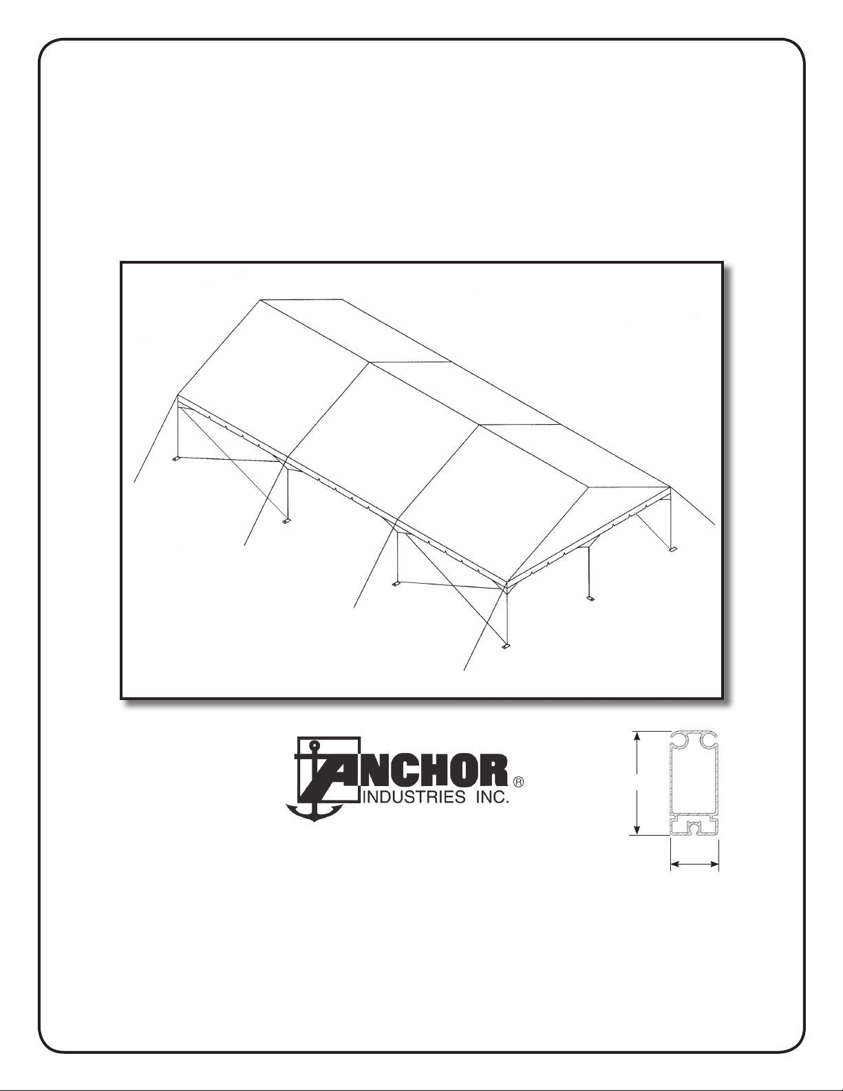
Navi-Trac® Frame Tent
30’ Wide Gable End System
Please read all assembly / installation instructions before the installation or removal of this product.
WEB
EC4714
5.0”
EVANSVILLE, INDIANA
2.3”
1100 Burch Dr., Evansville, IN 47725
Ph. 812-867-2421 • Fax. 812-867-0547
E-mail: tents@anchorinc.com • www.anchorinc.com
NAV30GE 1113
Page 2

Table of Contents
Page No. Assembly Step
3 Introduction
Inspect Site
Frame Terminology
4 Component Illustrations
5 30’ Navi-Trac Component List Table
6 30’ Navi-Trac Component List Table Cont’d
7 Safety Guidelines
8 Squaring the Tent - Footprint Layout
9 Web Guy - Staking Guidelines
Assembling the first Beam
10 Layout of all Beams
Erecting second Beam first
11 Connecting the First Two Beams
12 Installing Purlins
Completing First Bay
Completing the Top Frame
Installing the Gabled End Frame
13 Installing Guy Webs
X-Cabled Bays
14 Installing Mid Panels
Installing Gabled End Panels
15 Safe Attachment of Pull Ropes to Fabric
Fabric Tensioning
16 Completed Gabled End Unit Illustration
Alternate Hip End/ Gabled End Configuration
17 Combining Hip and Gabled End Assembly Steps
Component Changes for Hip/ Gabled End Configuration
18 Diagonal Beam Brace
19 Wall Installation
20 Ground Bar Keeper
21 Limits of Liability
2
Page 3
INTRODUCTION:
Like the hip-end version, the gabled end NAVI-TRAC frame is made up of extruded aluminum members joined by weldments. The aluminum frame members themselves are extruded with channels into which the NAVI-TRAC fabric “kedar” is fed. However, the gabled
end version of the Navi-Trac differs from the Hip End version in a number of ways:
1. All the beams are parallel to each other.
2. Beam base plates are hinged for pivoting to a vertical position. End Upright plates are fixed, non-pivoting.
3. The eave fittings are the MCW style that allows a simple drop-in action for purlin installation, rather
than the slip joint of the hip end configuration.
4. Fabric middle bays are installed into the channels of adjacent beams one bay at a time.
5. Gabled End fabric is intalled simply into the outer channel of the end beams and tensioned to the
Gabled End uprights.
6. Corner guys are in one direction only, parallel to the beams.
NOTE: It is possible to combine the hip end and gabled end styles within one building unit (see kit #3); however this assembly manual
focuses on the gabled end configuration only. The last few pages describe the hip/gabled combination and refer the customer to the
hip end assembly manual for the hip end part of the building unit.
INSPECT SITE
CAUTION:
Consult your local utility locator service or the National Utility Locating Contractors Association (NULCA) prior to
installation.
Prior to actual tent assembly, be sure to look up, down, above & below for obstacles, pipes, wires, trouble, etc.
MCW
UGT
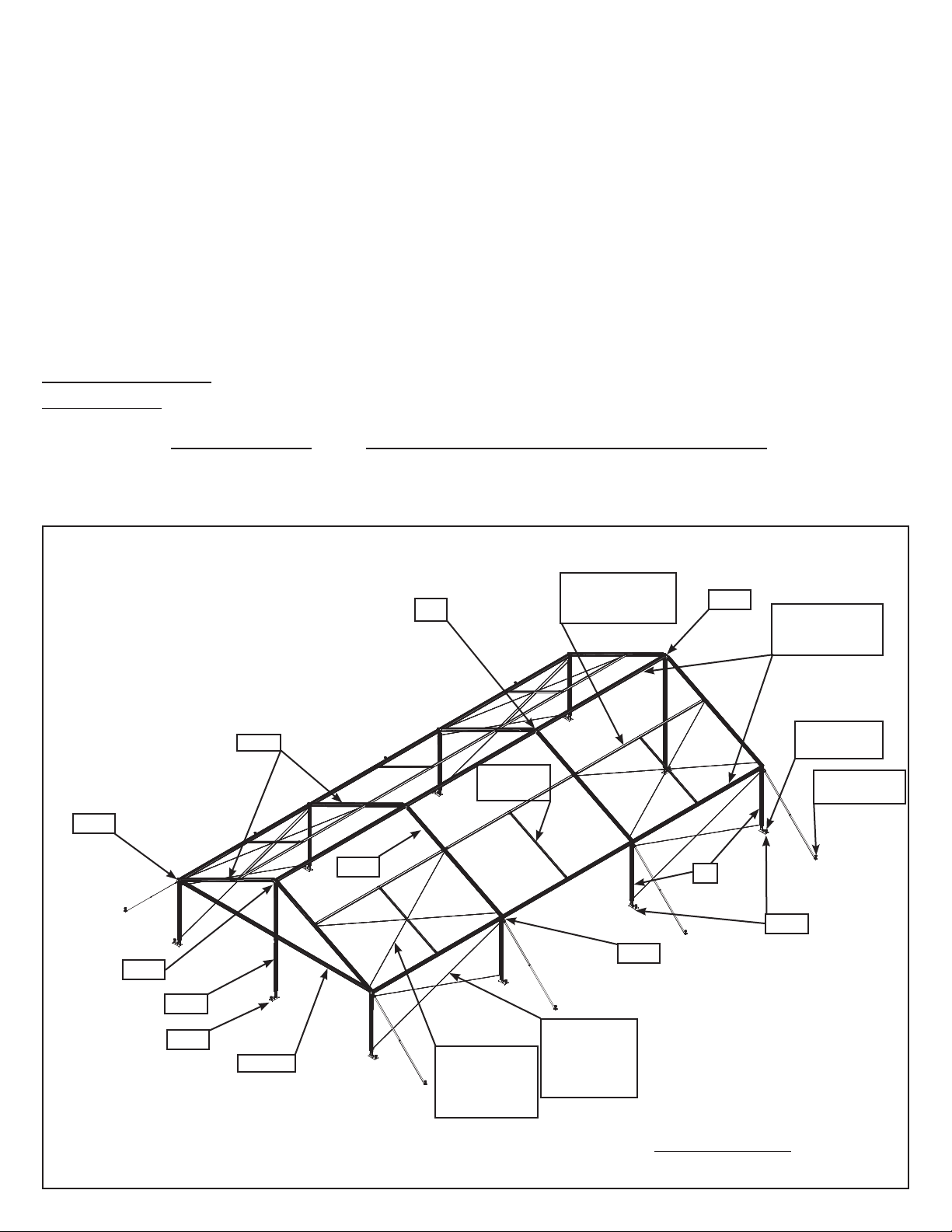
30’ Gabled Navi-Trac Frame Terminology
P1, P2 OR P3
R16-2
XRB
RW
Dependent upon
mid bay width.
P1 for 20’
bay only.
MCW
RWE
U8
ER10, 15, or 20
Dependent upon
mid bay width.
30” Stake at
Base Plates
42” Stake for
each Guy
BHW
UG-15
BFW
EW15
X-4, 5 or 6
Dependent
upon mid bay
width.
X-1, 2 or 3
Dependent
upon mid bay
width.
See Component List Table on Pages 5 &
6 for component descriptions.
3
Page 4
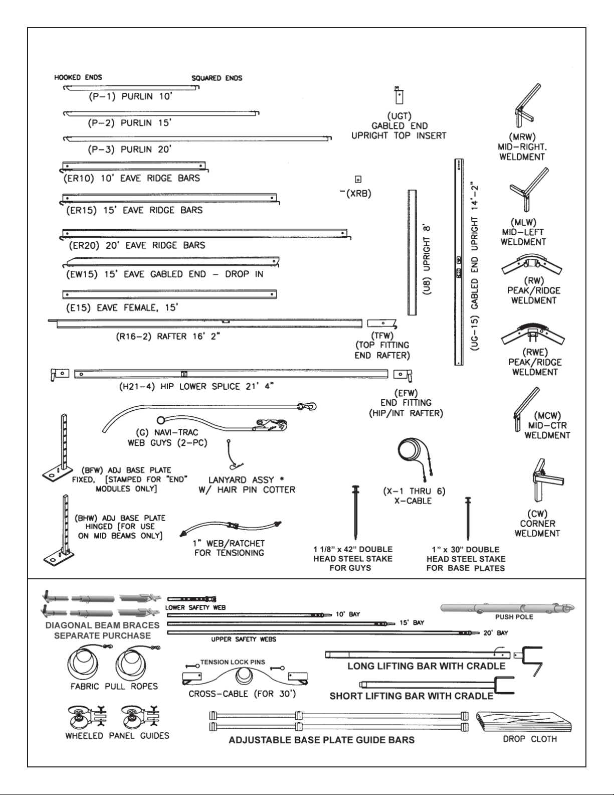
30’ NAVI-TRAC COMPONENT ILLUSTRATIONS
INSTALLATION TOOLS
4
Page 5

30’ NAVI-TRAC COMPONENT LIST
A MINIMUM GABLED UNIT CONSISTS OF (1) KIT #1, (1) KIT #2 AND (2) EXTENSION
MIDS. TO EXTEND THE LENGTH FURTHER, SIMPLY ADD ADDITIONAL EXTENSION
MIDS. STARTER MIDS REQUIRED WITH HIP ENDS ONLY.
I.D. 30’ GABLED END NAVI-TRAC
LABEL
(LETTER ON
DRAWING)
COMPONENT DESCRIPTION
CODES
(STAMPED OR
TAPED)
GBL
KIT
1
GBL
KIT
2
HIP
KIT
3
20’
MID
STR
20’
MID
EXT
15’
MID
STR
15’
MID
EXT
10’
MID
STR
10’
MID
EXT
EXTRUSIONS W/CHANNELS
E15 EAVE - FEMALE 15’ 4
ER10 EAVE/RIDGE - DROP-IN 10’ 33
ER15 EAVE/RIDGE - DROP-IN 15’ 3 3
ER 20 EAVE/RIDGE - DROP-IN 20’ 3 3
EW-15 EAVE/GABLED END, DROP-IN 15’ 2 2
R16-2 RAFTER 16-2 2 1 2 22222
H21-4 HIP LOWER SPLICE 21-4 (30’) 2
PURLINS
P1 PURLIN 10’ 2 2 2 2
P2 PURLIN 15’ 22
P3 PURLIN 20’ 2 2
UPRIGHTS
U8 UPRIGHT - 8’ 2 3 2 22222
UG-15 END UPRIGHT - 14’-2” 1 1
WELDMENTS, FITTINGS & PLATES
BFW ADJ. BASE PLATES W/INSERTS (FIXED) “END” 1 1 3 2 2 2
BHW ADJ BASE PLATEW/INSERTS (HINGED) 2 2 2 2
CW CORNER WELDMENTS 2
EIW END INTERMEDIATE WELDMENTS 1
MLW MID LEFT WELDMENTS 2 2 2
MRW MID RIGHT WELDMENTS 2 2 2
MCW MID CENTER WELDMENTS 2 2 2 2
RW PEAK/RIDGE WELDMENT 1 11111
RWE GABLED END RIDGE WELDMENT 1 1
UGT GABLED END UPRIGHT TOP INSERT 1 1
XRB X-CABLE RAFTER BRACKET 4 4
TFW TOP FITTING (END RAFTER) W/HDWR 1
EFW END FITTING (HIP/INT. RAFTER) W/HDWR 4
CONTINUED ON NEXT PAGE
5
Page 6

30’ NAVI-TRAC COMPONENT LIST
CONTINUED FROM PREVIOUS PAGE
I.D. 30’ GABLED END NAVI-TRAC
LABEL
(LETTER ON
DRAWING)
X-1
X-2
X-3
X4
X5
X6
COMPONENT DESCRIPTION
CABLES
UPRIGHT X-CABLES FOR 10’ MID BAY** GREEN
UPRIGHT X-CABLES FOR 15’ MID BAY** GREEN
UPRIGHT X-CABLES FOR 20’ MID BAY** GREEN
LOWER ROOF X-CABLES FOR 10’ MID
BAY A**
LOWER ROOF X-CABLES FOR 15’ MID
BAY A**
LOWER ROOF X-CABLES FOR 20’ MID
BAY A**
CODES
(STAMPED OR
TAPED)
NAV-BAY10-U8
NAV-BAY15-U8
NAV-BAY20-U8
RED
NAV-BAY10
RED
NAV-BAY15
RED
NAV-BAY20
GBL
GBL
HIP
20’
20’
15’
15’
KIT
KIT
KIT
MID
MID
MID
MID
1
2
3
STR
EXT
STR
EXT
**OPTIONS OF 10’,15’, OR 20’ BAYS MUST
BE SPECIFIED.
[4] [4]
[4] [4]
[4] [4]
44
44
44
INSTALL AS SPECIFIED FOR
UNITS 100’ +
INSTALL AS SPECIFIED FOR
UNITS 100’ +
INSTALL AS SPECIFIED FOR
UNITS 100’ +
INSTALL AS SPECIFIED FOR
UNITS 100’ +
INSTALL AS SPECIFIED FOR
UNITS 100’ +
INSTALL AS SPECIFIED FOR
UNITS 100’ +
BOLTS AND HARDWARE
LANYARD ASS’Y W/HAIRPIN COTTER 4
1/2”-13 x 3” BOLT W/NYLOCK NUT 428222222
1/2”-13 x 3 1/2” BOLT W/NYLOCK NUT 1 1
10’
MID
STR
10’
MID
EXT
INSTALLATION TOOLS
CROSS CABLE FOR 30’ RED 1111 1 1
LOWER SAFETY STRAP W/RATCHET 4
UPPER SAFETY STRAP FOR 10’ BAYS 4
UPPER SAFETY STRAP FOR 15’ BAYS 4
UPPER SAFETY STRAP FOR 20’ BAYS 4
1/2” TENSION LOCK PIN (FOR CROSS
CABLE)
LONG LIFTING BAR WITH CRADLE 1
2222 2 2
PUSH POLE EXTENSION 1
SHORT LIFTING BAR WITH CRADLE 1
ADJ. BASEPLATE GUIDE BAR 2
FABRIC PULL ROPES 2
WHEELED PANEL GUIDES 2
DROP CLOTH (8’ x 30’) 1
(2) DIAGONAL BEAM BRACES
(SEPARATE PURCHASE)
Other component notes:
1. For X-Cables for units 100’ or longer, see page 13 for quantities and installation.
2. Stakes and Guys are not included in this table. See staking guidelines on Page 9.
6
Page 7

NAVI-TRAC Installation Safety Guidelines
Your installation techniques will evolve to fit the needs of your clients, the experience level of your crews, the nature of other
tentage on-site, and the equipment that you have most readily available. We encourage you to begin with a crew of (4)
workers and only reduce this number as your experience level allows you to do so
safely. Whatever techniques you adapt for your crews, we encourage you to keep safety utmost in mind.
Please read through this assembly manual completely before beginning your installation. Be sure the proper equipment,
crew and safety precautions are in place. We hope that you enjoy the design features of the NAVI-TRAC each time the unit
is installed.
1. It is recommended that workers wear safety shoes and hard-hats on site.
2. When moving beam sections by hand, use proper lifting techniques to protect the back, and avoid pinching fingers
while making hardware connections.
3. Never permit bystanders or uninvolved to stand or walk even briefly in the falling path of a beam as it is being raised
or lowered.
4. Be aware to avoid contact of beams with any overhead power lines near the site.
5. When anchoring the structure, avoid all underground power lines and gas lines or other utility easements. Local
authorities should be able to map the location of these obstacles.
6. Keep site clear of debris to avoid tripping, especially while carrying components or bundles of fabric.
7. Do not drag bundles of fabric on concrete, asphalt, or ground as this can cause damage to the fabric from abrasion
through the bag.
8. When lifting the NAVI-TRAC Hip End frame (See Appendix), be sure to use the heavy duty NAVI-TRAC frame lift.
The standard Anchor frame lift was not designed for the weight of the NAVI-TRAC frame. When lifting each side of
an end section, (2) NAVI-TRAC frame lifts should be used.
9. Before pivoting beams to vertical, clear the area of items that could cause tripping or slipping.
10. Before pivoting middle beam, install the cross-cable for safety bracing. On the 50’ NAVI-TRAC, the cross-cable
should be left in place as an essential part of the structure.
11. NOTE: Hinged baseplates are used on all beams in the Gabled End Configuration. However, if the Hip End is con
structed on either, or both ends of the unit, the base plates in the hip end module should all be the non-pivoting,
fixed plates. Use of hinged baseplates in the end module could cause the end module to collapse during installation.
12. When using ladders to make peak connections, be sure the ladder is tall enough that workers can reach the peak
from a ladder step consistent with the safety recommendations for the ladder being used. On middle beams, secure
the eaves before climbing the ladder to secure the peak.
13. For any Gabled End NAVI-TRAC of 100 ft or more in length, one middle bay must be cross-cabled both in the over
head and at ground level in an “X” fashion on both sides for each 100 ft of length (see illustration on page 13.)
14. For proper loading and anchoring information, consult the appropriate NAVI-TRAC blueprint available from Anchor
Industries Inc.
15. If a Hip End is used on either end of the unit, before installing fabric, verify that all hip, brace, and rafter pins are
seated into weldment fittings and secured by lanyard pins.
16. The installation method described herein requires coordination of tasks between workers. A safe installation is
dependent on alertness and coordination.
17. Before lifting Gabled End top frame to install uprights, always guy out and stake at least both corners of the side or
end being lifted. This will help maintain the intended footprint and will protect against uplift from the wind that could
move or flip the tent, causing damage to the tent and/or severe injury to workers.
7
Page 8

SQUARING THE TENT - FOOTPRINT LAYOUT
BASE PLATE
A
LENGTH OF TENT
D
LOCATING
THE FOUR
PRIMARY
CORNERS
DIAGONAL
DIAGONALS MEASURED TO
CENTER OF BASE PLATE
STAKE HOLES.
WIDTH OF TENT
B
DIRECTIONS FOR SQUARING THE TENT
1. USE A TAPE MEASURE TO MARK THE ENDS OF A LINE FOR ONE END (“A” TO “B” ABOVE) EQUAL TO THE EXACT WIDTH OF THE UNIT. NOTE: FOR EASIER
INSTALLATION, MARK THE WIDTH FROM STAKE HOLE TO STAKE HOLE OF THE BASEPLATES, AS SHOWN IN BELOW CHART.
2. HOLD THE “0” END OF ONE TAPE AT POINT “A” AND THE “0” END OF ANOTHER TAPE AT POINT “B”.
3. EXTEND THE FIRST TAPE ALONG ONE SIDE OF THE UNIT TO A MEASUREMENT EQUAL TO THE EXACT LENGTH OF THE TENT.
4. CONSULT THE CHART BELOW TO FIND THE DIAGONAL FOR THE TENT YOU ARE BUILDING.
5. EXTEND THE SECOND TAPE TO A MEASUREMENT EXACTLY EQUAL TO THIS DIAGONAL.
6. BRING THE TWO TAPES TOGETHER SO THAT THE LENGTH MEASUREMENT OF ONE LIES DIRECTLY ON THE DIAGONAL MEASUREMENT OF THE OTHER. PULL
THE TAPES TIGHT AND MARK THEIR INTERSECTION. THIS WILL LOCATE A FAR CORNER (POINT “D” ABOVE).
7. SWITCH TAPES SO THAT TAPE 1 (ABOVE) MEASURES THE DIAGONAL AND TAPE 2 (ABOVE) MEASURES THE LENGTH. THIS WILL LOCATE POINT “C” ABOVE.
8. WITH THE FOUR PRIMARY CORNERS LOCATED, LAY OUT BASEPLATES AND UPRIGHTS ACCORDING TO THE NUMBER OF BEAMS TO BE INCLUDED IN THE
BUILDING UNIT. MEASUREMENTS GIVEN ARE TO THE CENTER OF THE STAKE HOLE OF EACH PLATE.
C
DIAGONALS FOR SQUARING FOOTPRINT
LENGTH OF TENT
DIAGONAL SHOWN IN FEET-INCHES (TO NEAREST INCH) - - TO CENTERS OF STAKE HOLES.
STAKE HOLE)
(STAKE HOLE TO
WIDTH OF TENT
8
Page 9

WEB GUY - STAKING GUIDELINES
REQUIRED DISTANCE OUT BETWEEN FRAME UPRIGHTS
AND STAKE LINE IS EQUAL TO THE UPRIGHT HEIGHT.
(FOR EXAMPLE, 8’ UPRIGHT = 8’ STAKE-OUT DISTANCE.)
(1) 30” Stake through
base plate. Drive into
ground as far as possible.
42” Stake driven through stake plate.
Stake must be driven into ground as
far as possible. (1) per upright as
shown for Gabled End Units.
ASSEMBLE FIRST BEAM
MCW (2)
9
10
U8 (2)
BHW (2)
1
2
(1) STAKE PER BASE PLATE
MAKE CONNECTIONS IN NUMBER SEQUENCE
SHOWN. STAKE PLATES BEFORE
ERECTING.
UPRIGHT HEIGHT
STAKE-OUT DISTANCE =
RW ON MID BEAMS, RWE ON END BEAMS
8
XRB (2) FOR
X-CABLED
BEAMS ONLY
USE CROSS CABLE AS AN INSTALLATION TOOL TO SQUARE FIRST
BEAM BEING RAISED. OPTIONAL ON
OTHER BEAMS, DEPENDING ON TERRAIN. NOT REQUIRED FOR FINAL 30’
CONFIGURATION.
7
R16-2 (2)
6
5
3
4
9
Page 10

LAYOUT OF ALL BEAMS
IMPORTANT NOTE: IF YOU WILL BE USING THE OPTIONAL
DIAGONAL BEAM BRACES, LAY OUT ALL BEAMS IN THE
SAME DIRECTION, DO NOT BUTTERFLY. SEE DIAGONAL
BEAM BRACE USE AT THE BACK OF THIS MANUAL.
CROSS CABLE USED FOR
SQUARING FIRST BEAM BEING
RAISED. OPTIONAL ON OTHER
BEAMS. NOT REQUIRED FOR
FINAL UNIT CONFIGURATION.
UPPER ENDS OF ALL XCABLES ATTACHED BEFORE
BEAMS ARE RAISED.
FIRST (2) BEAMS BUTTERFLIED
SO THAT ADJACAENT BASE PLATE
STAKES CAN BE USED FOR SAFETY GUYING. (2ND BEAM WILL BE
RAISED FIRST.)
ADJUST BASE PLATE GUIDE BARS
FOR PROPER SPACING AND ALIGNMENT OF BASEPLATES. (DROP
BAR FITTING OVER PINS IN BASE
PLATES.)
ALL PLATES ARE STAKED USING
30” STAKES.
2-PC SAFETY WEBS:
1. LOOP (4) LOWER SAFETY WEBS OVER
STAKE HEADS OF THE ADJACENT BASE
PLATES, BEAMS 1 & 3 (RATCHET ENDS
UP).
2. CHOOSE (4) UPPER SAFETY WEBS
LABELED FOR 10’, 15’, OR 20’ BAY
SPACING, AS NEEDED FOR YOUR UNIT.
3. ON THE TRAILING WEBS (TO BEAM #3),
INSERT THE LOOSE, HANGING ENDS OF
UPPER WEBS INTO THE RATCHETS OF
THE LOWER SAFETY WEBS. PULL ABOUT
1 FT OF WEB THRU THE RATCHET.
LEAVE PLENTY OF SLACK.
4. SNAP UPPER ENDS OF UPPER WEBS
TO THE EAVE BRACKETS OF THE BEAM
TO BE RAISED.
5. LEAVE THE LEADING WEBS (TO BEAM
#1) LOOSE AND HANGING UNTIL BEAM IS
UP.
ERECTING 2nd BEAM 1st
WORKERS LIFT FIRST AT THE
PEAK, THEN SHUFFLE SIDEWAYS
TOWARD THE UPRIGHTS.
AS THE 2ND BEAM PIVOTS
TOWARD VERTICAL, THE TRAILING SAFETY WEBS DRAW
TIGHTER.
10
Page 11

SECURING THE 1st VERTICAL BEAM
ON THE LEADING 2-PC SAFETY WEBS,
WORKERS INSERT LOOSE ENDS OF UPPER
SAFETY WEBS INTO THE RATCHETS OF
THE LOWER SAFETY WEBS.
USING RATCHETS, ADJUST LEADING AND TRAILING SAFETY WEBS AGAINST EACH OTHER ON BOTH
SIDES OF THE STRUCTURE TO SECURE AND VERTICALLY ALIGN THE BEAM.
ERECTING THE 2nd BEAM
WITH 2nd BEAM SECURED, THE 1st BEAM
IS ROTATED TOWARD IT. 2 OR 3 WORKERS SHOULD HOLD THE BEAM AT VERTICAL
UNTIL EAVE BARS (ER20) ARE INSTALLED.
SECURING THE 2nd BEAM WITH DROP-IN RIDGE/EAVE BARS
DROP-IN RIDGE/EAVE BARS CONNECT 1st AND 2nd BEAMS. DROP
ONE HOOK END OF BAR INTO EAVE
FITTING. USE LIFTING CRADLES TO
POSITION 2nd END.
11
Page 12

INSTALLING PURLINS AND RIDGE BARS
USE SAME TECHNIQUE AND THE
LONG LIFTING POLE WITH CRADLE
TO INSTALL THE PURLINS AND
RIDGE EAVE BAR (AT THE PEAK)
COMPLETING THE 1ST BAY
REMOVE CROSS-CABLE FROM 2ND BEAM
COMPLETING THE TOP FRAME
REPEAT PREVIOUS STEPS UNTIL
ALL BEAMS ARE VERTICAL AND
BOTH END BAYS ARE X-CABLED,
AS SHOWN.
IN 20’ MID BAYS, INSTALL A SUPPORT PURLIN
BETWEEN THE EAVE AND THE PURLIN AT THE MIDRAFTER LOCATION. THIS SUPPORT WILL BRACE
AGAINST INWARD DEFLECTION OF THE EAVE BAY
THAT COULD OTHERWISE RESULT IN WATER PONDING IN THE 20 FT BAY.
INSTALLING GABLED END
FRAME
1
3
2
EW-15
15’
INSTALL GABLED END FRAME. MAKE CONNECTIONS
IN THE ORDER SHOWN.
5
6
UG-15
BFW
4
12
Page 13

INSTALLING GUY WEBS BEFORE INSTALLING FABRIC
ATTACH GUY WEBS TO EAVE WELDMENTS AND
STAKE OUT AT 45º. SEE STAKING GUIDELINES
ON PAGE 9.
* IMPORTANT NOTE: REFER TO CAUTION STATEMENT #2 FOR IMPORTANT WARNING ABOUT NUMBER OF STAKES
SUPPLIED. (SEE BACK PAGE OF THIS MANUAL)
THE INSTALLER MUST USE THE LOCAL SOIL CONDITIONS TO CALCULATE THE ACTUAL NUMBER OF
STAKES REQUIRED AND IS RESPONSIBLE FOR THE STAKING PATTERN AND CONFIGURATION.
PROVIDES ANCHORING PACKAGES FOR COMMON SOIL CLASSIFICATIONS; CONTACT YOUR TENT SALES REPRESENTATIVE
FOR MORE INFORMATION.
ANCHOR
X-CABLED BAYS
STAKE PLATES AT PROPER SPACING BEFORE
INSTALLING THE X-CABLES. THEN, ADJUST
TURNBUCKLES UNTIL CABLE IS SNUG
RAFTER X-CABLES ARE
COLOR-CODED RED
AND LABELED 10, 15, OR
20 ACCORDING TO BAY
SIZE.
X-CABLING IS IDENTICAL
ON BOTH SIDES OF THE
STRUCTURE.
UPRIGHT X-CABLES ARE COLORCODED GREEN AND LABELED 10,
15, OR 20 ACCORDING TO BAY
SIZE.
NAVI-TRAC UNITS 100 FT. OR MORE IN LENGTH MUST HAVE AN X-CABLED
BAY NEAR THE MIDDLE OF THE UNIT (AND/OR EQUALLY SPACED) FOR
EVERY 100 FT. UNIT OF LENGTH.
FOR CABLE CONNECTIONS AT MID
PORTION OF RAFTERS, INSERT THE
BOLTS IN THE HOLES OF THE RAFTER THAT ARE JUST BELOW THE
PURLIN CONNECTION. THREADS
PURLIN
REMOVE NUTS FROM THE BOLTS THAT PIN THE
BASEPLATE TO THE UPRIGHT. TURN BOLTS SO THE
THREADS ARE TO THE INSIDE (TOWARD CENTER OF
BAY). THREAD CABLE EYE NUTS ONTO BOLTS TO
SECURE THE CABLE.
SHOULD POINT INWARD TOWARD
CENTER OF BAY. THREAD CABLE
EYE NUTS ONTO EACH BOLT TO
SECURE THE CABLES AS SHOWN.
SUBSTITUTE BOLTS FOR PINS AT THE
TOP OF BOTH UPRIGHTS AND BOTTOM OF BOTH RAFTERS. THREADS
SHOULD POINT INWARD TOWARD
CENTER OF BAY. THREAD CABLE EYE
NUTS ONTO EACH BOLT TO SECURE
THE CABLES AS SHOWN.
13
Page 14

INSTALLING MID PANEL
NOTE: TO ENSURE THAT MID
FABRIC GOES IN SMOOTHLY AND
TO MINIMIZE CHANCE OF DAMAGE TO FABRIC, ALWAYS USE THE
WHEELED PANEL GUIDE TO FEED
KEDAR INTO FRAME CHANNELS.
SEE PAGE 15 FOR INFORMATION ON
HOW TO ATTACH PULL ROPES TO
FABRIC.
INSERT FINGERS OF WHEELED
PANEL GUIDE INTO THE OPEN
END OF THE RAFTER AND
WELDMENT. TIGHTEN THE BUTTERFLY NUT. REVERSE FOR
OPPOSITE SIDE OF BAY.
PULL MID PANEL UP AND OVER THROUGH
CHANNELS IN RAFTER EXTRUSIONS.
INSTALLING 2-PC GABLED END
SECURE LACE LINE AT TOP
& BOTTOM WITH FASTEX
BUCKLES
WHEELED PANEL
GUIDE AT EAVE
RAFTER
WHEELED PANEL
GUIDE
STANDARD LOOP
& GROMMET
LACING
TIE OFF BOTTOM LOOP
USE LONG LIFTING
POLE TO PUSH EACH
HALF TO PEAK.
14
Page 15

SAFE ATTACHMENT OF PULL
ROPES TO FABRIC
KEDAR
FLAP - ONLY ONE
SIDE OF MID OR
END WILL HAVE
THE FLAP.
SNAP OF PULL ROPE MUST BE
FASTENED TO PULL WEB ON
UNDER SIDE OF FABRIC PIECES.
SNAP MUST FACE AWAY FROM
KEDAR.
FOLD CURTAIN AND CATENARY BACK
ON TOP OF MID SO THAT THEY ARE
OUT OF THE WAY.
FABRIC TENSIONING
TOP
TENSIONING WEB
(LEFT) W/ RING
CATENARY TAILS
UPRIGHT
DIAGRAM SHOWING UNDER
SIDE OF FABRIC AT EAVE.
TENSIONING
WEB (RIGHT)
W/ RING
TENSIONING RINGS
OVERLAPPED
WEB/RATCHET
ATTACH WEB/RATCHET
TO TRIANGLE RING AND
TENSION DOWNWARD.
1. USE WEB/ RATCHETS TO SECURE
CATENARY ARCHES TO UPRIGHTS, STAKE
BASEPLATES BEFORE TENSIONING WEBS.
TENSIONING METHOD:
1. PASS RING OF LEFT TENSIONING WEB THROUGH OPPOSITE CATENARY RING.
2. PASS RING OF RIGHT TENSIONING WEB THROUGH ITS OWN CATENARY RING (PASSING OVER THE LEFT WEB).
3. CONTINUE RING OF RIGHT TENSIONING WEB THROUGH OPPOSITE CATENARY RING.
4. OVERLAP BOTH TENSION RINGS. ATTACH WEB/RATCHET AND TENSION DOWNARD AGAINST TENSION HOLE IN
UPRIGHT. (CATENARY RINGS SHOULD MOVE CLOSER TOGETHER AS RATCHET IS TIGHTENED.)
15
Page 16

30’ x 60’ GABLED END NAVI-TRAC
COMPLETED 30’ GABLED END NAVI-TRAC WITH
FABRIC INSTALLED AND TENSIONED, GUY
WEBS STAKED AND RATCHETED TIGHT. TO
MEET ENGINEERING REQUIREMENTS WALLS
SHOULD BE INSTALLED ON ALL (4) SIDES.
ALTERNATE HIP/GABLED END COMBINATION
USING KIT #3 FOR THE HIP COMPONENTS
(SEE THE FOLLOWING PAGE FOR ASSEMBLY
REFERENCE)
16
Page 17

HIP/GABLED END COMBINATION UNIT
SEE THE STANDARD NAVI-TRAC
INSTALLATION INSTRUCTIONS FOR
ASSEMBLY OF THE HIP END UNIT.
EXTENSION BEAMS ARE PIVOTED
IN THE SAME MANNER AS SHOWN
PREVIOUSLY IN THIS GABLED END
ASSEMBLY INSTRUCTION.
SEE BELOW FOR COMPONENTS THAT
MUST BE SUBSTITUTED IN HIP END UNIT
(SEE KIT #3)
HIP (KIT #3) COMPONENTS
(NOTE: MRW & MLW ARE SUPPLIED
WITH THE “STARTER’ FRAMES)
EFW
MRW
H21-4
EIW
CW
TFW
E15
MLW
BFW
17
Page 18

DIAGONAL BEAM BRACE USE (OPTIONAL PURCHASE)
The diagonal beam brace is an optional
purchase and is used for help in raising and stabilizing the first raised beam.
These are sold in sets of two and are
meant to be used simultaneously on
both sides of the frame.
The diagonal beam brace is adjustable
and may be used on all standard sized
mids and upright heights.
The first step in using the diagonal
beam brace is to adjust it to the size
required. Slide the bar out until you see
the label for your particular mid size and
upright height, then pin to size.
Insert top of beam brace into pad eye
weldment and pin as shown in Figure 2.
SECOND BEAM LAYING ON GROUND
FIRST BEAM BEING
RAISED
As beam is being raised, guide bottom
of brace to the base plate of the second
beam. Attach brace to base plate and
pin as shown in Figure 3.
Raise second beam.
Attach purlins and cables.
Remove braces.
TOP OF DIAGONAL BEAM
BRACE FITS INTO HOLE
OF PAD EYE, PIN TO
KEEP IN PLACE.
DIAGONAL
BEAM BRACE
TOP OF DIAGONAL BEAM
BRACE PINNED INTO PAD
EYE. SEE FIGURE 2.
NOTE: IN THIS OPTION, BEAMS ARE ALL LAID IN THE SAME
DIRECTION.
Figure 1
NEWLY
RAISED
BEAM.
Figure 2
SLIDE BOTTOM OF BEAM BRACE
OVER PIN IN BASE PLATE. USE
HITCH PIN TO KEEP IT IN PLACE
DIAGONAL
BEAM BRACE
Figure 3
NEWLY RAISED
BEAM.
DIAGONAL BEAM BRACE
SHOWN PINNED IN
PLACE
18
Page 19
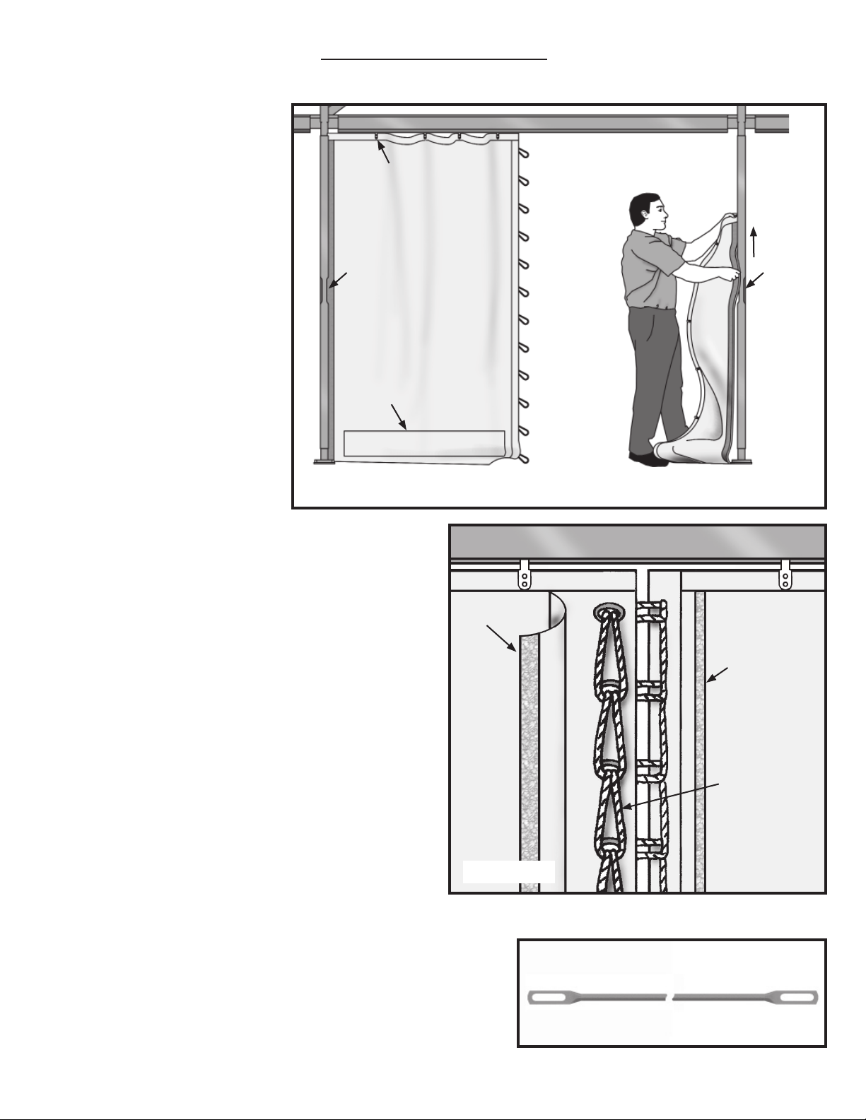
Wall Installation
Step 1
Determine which side of wall is inside
and out. Ground bar pockets are on
outside, Lace flap is on inside. Start by
feeding top of kedar edge into channel
opening until top of wall is as far as it
will go. (Figure A)
Insert the bottom edge of kedar into
channel opening and feed down until
wall is smoothly installed into upright.
Step 2
Starting with wall tab nearest the lace,
insert into slotted opening in bottom
channel of eave bar. Feed rest of wall
tabs into channel.
Step 3
Repeat with the matching half of the
wall.
Step 4
Lace wall starting at top of wall bringing top loop thru the top grommet of
matching half of wall to inside of wall.
Continue with this process looping next
loop thru grommet and then the upper loop until all loops are laced. (See
Figure B) Tie off bottom loop to keep
lace together.
Wall tabs
Channel
opening
Ground bar
pocket
Lace Flap
Eave Bar
Outside View
Eave Bar
Channel
opening
Figure A
Velcro for lace
fl ap
Step 5
Slide ground bar (Figure C) thru pocket
on outside of wall. Fasten to frame using the ground bar keeper as noted on
next page.
Inside View
Lace loops thru
grommets
Figure B
Ground bar
Figure C
19
Page 20

Navi-Trac Ground Bar Keeper Instructions
Upright prong fi ts into this part of
upright.
Prong with no hole inserts up into upright.
This end to outside
of tent.
Cross sectional view of upright.
Groundbar keeper for intermediate upright.
Base Plate Inserted
into upright.
Wall with kedar already slid
into upright.
Groundbar slid into
pocket.
Inserting keeper up into
bottom of upright on outside
corner of tent.
Groundbar keeper for Corners.
Corner Upright
Bottom View looking up
into upright with Groundbar
keeper inserted.
Gable End Leg Cover
Slide groundbars onto
prongs and pin into place as
shown.
For Gable End Uprights, This
Gable End Leg Cover may be
attached at bottom of uprights
for use with groundbar keepers.
20
Page 21

EVANSVILLE, INDIANA
PHONE NUMBER
812· 867· 2421
FAX NUMBER
812· 867· 0547
Anchor products are of superior design and operate best within the parameters of these instructions. It is imperative
that the instructions be carefully read and COMPLETELY FOLLOWED. Please read installation instructions before the
installation or removal of this product. Installation instructions are available online at www.anchorinc.com or by calling
1-800-544-4445.
CAUTION:
1. For each installation, the installer is solely responsible for evaluating the site and the proper securing method
determined. Some soils require different staking or securing than that provided with the tent. Due to this variety of
soil conditions, these are the manufacturer’s suggested sequence of installation procedures. Anchor’s responsibility
is limited to the manufacture of the tent parts and materials. We are not responsible for methods that installers may
choose to erect and secure the tent to the ground.
2. The number of stakes suggested in the installation instructions do not necessarily meet all or any relevant codes
on the site of the tent installation. The number of stakes suggested will, in many cases, keep the tent erected,
however, due to various soil conditions; these stakes will be insuf¿ cient to keep the tent secure in high winds.
It is the tent installer’s responsibility, not the manufacturer, to determine the appropriate number of stakes to meet
the necessary wind loads on the site. Regardless of the number of stakes we suggest, we make no representation
or warranty as to whether this speci¿ c number of stakes will meet the local tent code. Anchor does not, nor can
it make any suggestions, representation, or warranties about the adequate staking required at each speci¿ c
installation site. Staking information provided in the installation instructions is not a suggestion about what is
necessary to meet a site-speci¿ c load.
For additional important information, consult: “The IFAI Procedural Handbook For the Safe Installation and
Maintenance of Tentage” and the IFAI Pocket Guide “Pullout Capacity of Tent Stakes”, both available from
the IFAI Tent Rental Division or on our website.
3. Inasmuch as the weather is unpredictable, good judgment and common sense must be incorporated within
installation guidelines. It is the responsibility of the tent installer/maintainer to determine the severity of the weather,
proper time and method of installation and/or erection and disassembly. Note: We recommend that snow and
ice be removed from the tent surface as soon as possible because accumulation will damage the tent
or fabric structure. Please consult with our Engineering Department about the maximum loads for each
product.
This product has been manufactured to meet code requirements. For the safety of all occupants, evacuation is
recommended if threatening weather occurs, or if there is any doubt concerning the safe use of this product.
4. Proper safety equipment should be used at all times to insure a safe installation and take down. We suggest a
careful evaluation be made to determine safety equipment needed, such as hard hats, steel-toe shoes, safety
glasses and other as required. It is our desire that all installations are safe. Please be aware of hidden dangers
both underground, i.e., gas lines, water lines, electrical lines, etc. and above the tent such as power lines and
telephone lines.
5. Anchor stands behind its products in accordance with its standard Terms and Conditions of sale. A copy of our
Terms and Conditions of Sale can be obtained by contacting Anchor at the telephone number and/or address on
this document.
28.3 03-04-09
 Loading...